Article

Numerical Simulation of Depth Tracking Control of an Underwater Towed System Coupled with Wave–Ship Interference

1
Department of Naval Architecture and Ocean Engineering, South China University of Technology, Guangzhou 510640, China
2
Guangzhou Shunhai Shipyards Ltd., Guangzhou 511440, China
*
Author to whom correspondence should be addressed.
J. Mar. Sci. Eng. 2021, 9(8), 874; https://doi.org/10.3390/jmse9080874
Submission received: 26 June 2021 / Revised: 11 August 2021 / Accepted: 12 August 2021 / Published: 13 August 2021
(This article belongs to the Special Issue Marine Applications of Computational Fluid Dynamics)

Abstract

:
This paper presents a numerical study of the depth tracking control for an underwater towed system under wave–ship interference condition. To overcome the laminations of ignoring the hydrodynamic factors and wave–ship interference in the existing simulation model for the depth tracking operation of the underwater towed system, a numerical model combining the control system with the computational fluid dynamics (CFD) method based on the overset mesh technique is explored and constructed; the influence of towing ship and head waves is introduced into the numerical analysis of the underwater towed system; a depth control system based on the center of gravity adjustment is proposed and its control characteristics are discussed. The fluid motion around the towed vehicle and the towing ship is governed by the Navier–Stokes equations, and the overset mesh technique is applied for the numerical solution of the equations. The towing cable connecting the towed vehicle and towing ship is governed by the quasi-steady-state catenary equations. The depth tracking controller adjusting the longitudinal position of a shifting weight is constructed based on the proportional–integral–derivative (PID) algorithm. The simulation results show that the numerical simulation system is practicable, and the depth tracking control system is feasible, effective, and robust.

1. Introduction

The underwater towed system has been found widely used in the collection of marine environmental parameters [
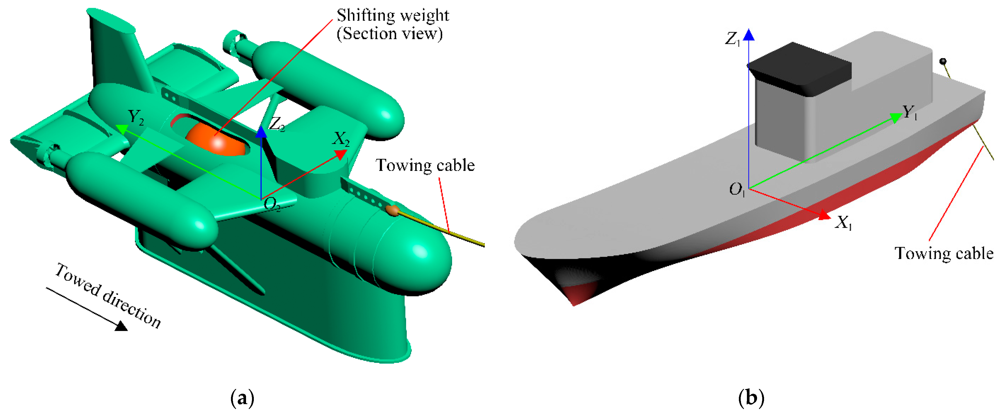
1]. A typical underwater towed system is usually composed of a towing ship, a towing cable, and a towed vehicle equipped with control mechanisms and corresponding control systems to control the trajectory or attitude of the towed vehicle. It is of practical significance to discuss the hydrodynamic and control characteristics under interference conditions in an underwater towed system’s research and development.
In studying the trajectory and attitude control performance of an underwater vehicle, many beneficial research and explorations have been conducted on the mathematical models or numerical approaches. Huy Ngoc Tran et al. [2] developed a tracking controller for a hybrid autonomous underwater vehicle (AUV); the controller considered the effect of the roll angle and model uncertainty, numerical simulations are carried out to analyze the robust stability of the proposed controller. Jinmo Park et al. [3] proposed a dynamics model based on an absolute nodal coordinate formulation and a 6-DOF equation; the forward running and turning behavior of an underwater towed system are discussed to validate the effectiveness of the dynamics model. Pham Nguyen Nhut Thanh et al. [4] presented a three-dimensional trajectory tracking controller for AUV vehicles; uncertain nonlinear model features, model uncertainty, and the roll motion’s effect are considered in the trajectory tracking controller. Wu, J.M. et al. [5] proposed an integrated hydrodynamics and control model based on the fuzzy sliding mode control (FSMC) algorithm; the umbilical cable and hydrodynamic behaviors of an underwater robot are governed by a finite difference method and the six-degrees-of-freedom equations of motion for submarine simulations, respectively. In another research, Wu, J.M. et al. [6] introduced the hybrid feed-forward and feedback control coupling with the incremental proportional–integral–derivative algorithm into the hydrodynamic model for a tethered underwater robot system; the trajectory following control of the tethered underwater robot is investigated. Francisco Curado Teixeira et al. [7] discussed the problem of depth tracking and attitude control of a towed vehicle whose controller is based on the nonlinear adaptive output feedback control law. Vu, M.T. et al. [8] proposed a new model of the behavior of an underwater vehicle affected by umbilical cable dynamics; the umbilical cable in this model is described by the governing equations based on the catenary equation method, the maneuvering behaviors of the underwater vehicle with an umbilical cable effect was simulated and instructive results were obtained. Cho, H. et al. [9], Vu, M.T. et al. [10] and Jung, D.W. et al. [11] investigated the control of a multi-marine vehicles system-integrated unmanned surface vehicle and underwater vehicle; the unmanned surface vehicle and the underwater vehicle are connected via an underwater cable, the performance of the system is demonstrated by an experimental method. Vu, M.T. et al. [12] investigated a station-keeping control of an underwater vehicle; the station-keeping control algorithm based on a sliding mode control theory is proposed and demonstrated by a series of simulations and experiments. In another study by Vu, M.T. et al. [13], the least square method and quadratic programming method were designed for the positioning controller; numerical results show that the controller using the quadratic programming method shows better performance. Much has been extensively discussed regarding the trajectory and attitude manipulation problems of different types of underwater vehicle systems, various dynamic control models or physical models have been proposed, and relevant numerical simulations or experiments have been investigated.
However, on the one hand, when it comes to trajectory and attitude control issues of underwater vehicles, most of the research usually focuses on the control topic, while relatively less attention is paid to the hydrodynamic factors considering the viscous effect. It is certain that hydrodynamics factors are indispensable in the discussions on manipulation problems of underwater vehicles. Further, there is less attention on the overall dynamics of the underwater towed system, especially considering the complex coupling among the towed vehicle, towing ship, towing cable, and the surrounding flow field under wave interference. On the other hand, the dynamic characteristics of the depth tracking operation by adjusting the center of gravity of the towed vehicle have been less explored, which hinders the understanding of the control mechanism of this control mode. Finally, few studies involve the towing ship hydrodynamic factors on the towed vehicle’s manipulation, which is non-negligible when the towing ship is small or suffering rough sea conditions.
The key to accurately predicting the hydrodynamic characteristics of a towed system under the control operation is to construct an accurate and practicable hydrodynamic model combing the towing ship, the towing cable, the towed vehicle, and the control system. For a better understanding of the depth tracking control characteristics, especially the hydrodynamic characteristics of an underwater towed system under an interference condition, the depth tracking operation of an underwater towed system in head waves is numerically simulated. The internal relationship between the depth tracking system, the control mechanism, and the vertical trajectory of the towed vehicle is analyzed. The depth tracking control model is based on the PID algorithm; the hydrodynamic behaviors of the towing ship and the towed vehicle in head waves are simulated by the computational fluid dynamics (CFD) method, the motions of the towed vehicle and the towing ship are described based on the overset mesh technique, the head waves are captured by the volume of fluid (VOF) method; the towing cable is described by the quasi-steady-state catenary equations. The dynamic characteristics of the underwater towed system under the control operation are discussed. The main contributions of this paper include the followings: firstly, a numerical model combining the control system with the CFD method based on the overset mesh technique is explored and constructed; secondly, the influence of the towing ship and head waves is introduced into the numerical analysis of the underwater towed system; thirdly, a depth control system based on the center of gravity adjustment is proposed and its control characteristics, especially its dynamic mechanisms, are discussed.
This paper is constructed as follows: Firstly, 
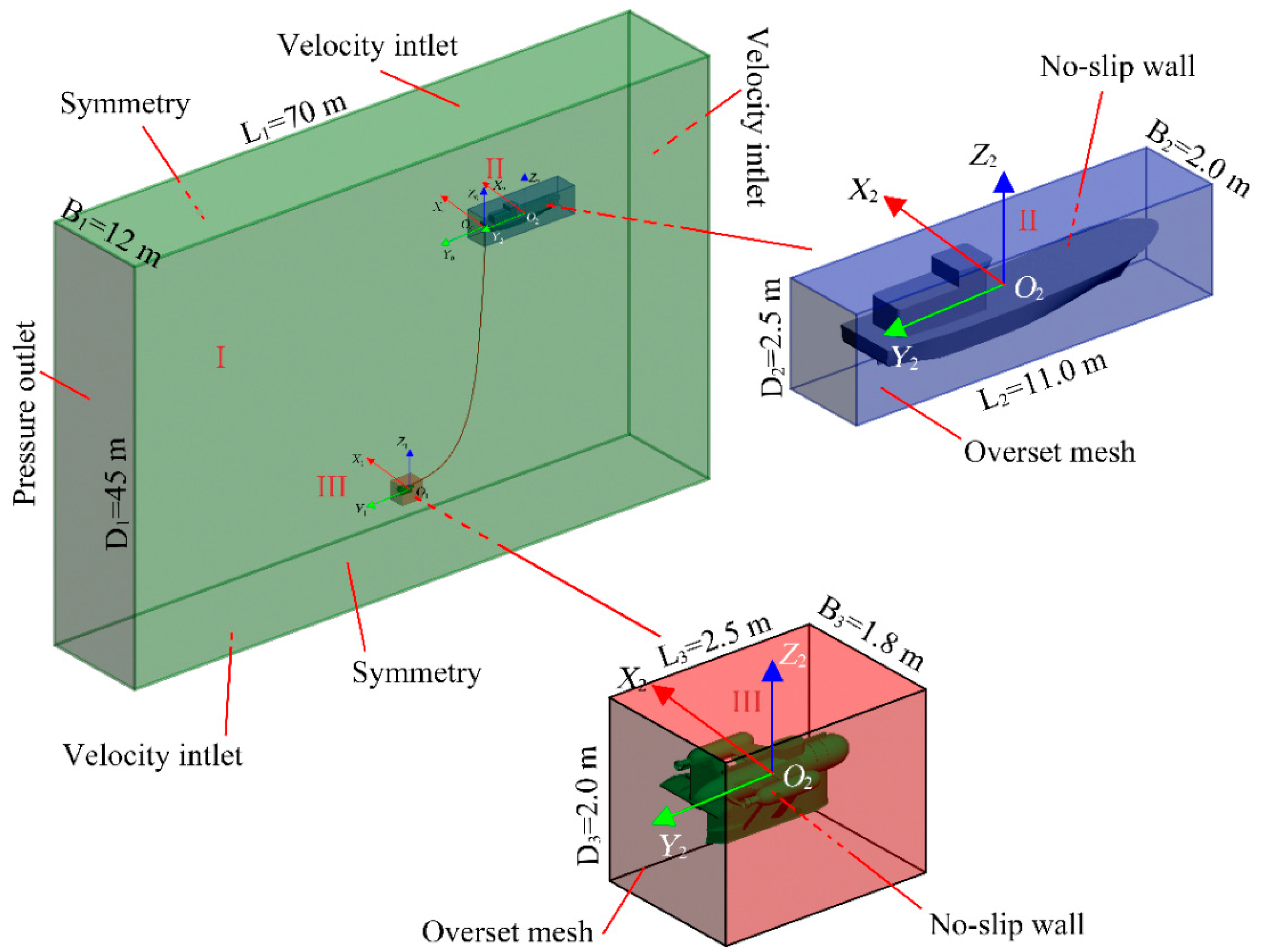
Section 2, the computational scheme used in this paper is introduced in detail. In this section, the assumptions of this paper are given first, and then the equations describe the flow field, the governing equations of the towed system are presented. The geometric models of the towed system are described. The division and definition of computational domains are introduced. Next, Section 3 briefly discussed the control mechanism of the depth control system. Next, Section 4, the feasibility of the numerical method is demonstrated by experimental results. Then, Section 5, numerical results are presented and discussed. Finally, Section 6 summarizes this paper and gives several conclusions.

2. Computational Scheme

2.1. Assumptions

The underwater towed system studied in this paper is presented in Figure 1, including a towing ship, a towed vehicle, and a towing cable connecting the towing ship and the towed vehicle. Some other definitions and assumptions were determined as follows:
  • In Figure 1, the upper endpoint Ps of the towing cable is at the tail of the towing ship, the lower endpoint Pt of the towing cable is located at the front and upper part of the towed vehicle; O0 is the initial position of Ps; O1 and O2 are the centers of gravity of the towing ship and the towing vehicle, respectively; O1-X1Y1Z1 is the coordinate system following the towing ship, O2-X2Y2Z2 is the coordinate system following the towed vehicle. The translational motions of the towed vehicle and the towing ship are described by the semi-fixed coordinate system O0-X0Y0Z0; G1 is the gravity of the towing cable; φs and φp are the tangential angles of the towing cable at the upper endpoint Ps and the lower endpoint Pt, respectively; Fs and Fp are the cable tensions at Ps and Pt, respectively.
  • Due to the symmetry of the flow field and the model, only the heave and pitch of the towing ship, and heave, pitch and surge of the towed vehicle were considered.
  • The hydrodynamic forces of the small diameter (5 mm) towing cable were neglected.

2.2. Governing Equation of Flow Field

The governing equations of the flow around the towed vehicle and the towing ship expressed as [14]
(1).
Continuity equation:
u i ¯ x i = 0   ( i = 1 , 2 , 3 )
(2).
Momentum equation:
ρ [ u i t + ( u i ¯ u j ¯ ) x j ] = P x i + ρ g i + x j [ μ ( u i ¯ x j + u j ¯ x i ) ρ u i u j ¯ ]             ( i , j = 1 , 2 , 3 )
where u i ¯ , u j ¯ represent the velocity components of the fluid, xi is the rectangular coordinate of space, ρ and μ are the density and dynamic viscosity coefficient, respectively; P is the mean value of pressure, t is the physical time, g i is the mass force component; ρ u i u j ¯ is the Reynolds stress term.

2.3. Motion Equations of the Towed Vehicle and the Towing Ship

The motion equations of the towed vehicle moving in the fluids can be written as
m d v d t = s p s a s s τ s a s + m g + F t
M d ω d t + ω   ×   M ω = s [ r s   ×   ( p s a s ) ] s [ r s   ×   ( τ s a s ) ] + r t   ×   F t
where m, v, and ω are the mass, the linear velocity, and the angular velocity of the towed vehicle, respectively; ps and τs are the normal force and shear force of the fluid acting on surface element s of the towed vehicle, respectively; as is the area vector of surface element s, g is the local acceleration of gravity, Ft is the cable tension of the towing cable at the connecting point Pt; rs and rt are the distance vector of the surface element s and the connecting point Pt, respectively; M is moment of inertia.
M = [ M x x M x y M x z M x y M y y M y z M x z M y z M z z ]
The motion equations of the towing ship moving in the fluids are very similar to that of the towed vehicle. The difference is that the cable tension Ft at connecting point Pt is replaced by the cable tension Fs at the towing point Ps, and the surface element s, the mass and motion parameters of the towed vehicle are changed to those of the towing ship.

2.4. Coupling Model of Towing Cable

The shape parameter equations of the towing cable are defined as [15]
{ x u = a λ + b sinh ( λ ) + α y u = a cosh ( λ ) + b 2 sin h 2 ( λ ) + β
λ 1 λ λ 2 , a = c m 0 g , b = c a k L r , c = m 0 L r g sin h ( λ 2 ) sin h ( λ 1 )
where (xu, yu) are the coordinates of a point on the towing cable; m0, k, and Lr is the mass per unit length, the stiffness, and the relaxation length of the towing cable, respectively; a, b and c are intermediate variables; α and β are the integral constants, λ is the curve parameter associated with the tangential angle φ of a certain point on the towing cable, which can be written as:
sin h λ = tan φ
As presented in Figure 1, Ps and Pt are the upper and the lower endpoint of the towing cable, respectively. Ps and Pt are defined in the coordinate system O1-X1Y1Z1 and O2-X2Y2Z2, respectively, and move with the towing ship and the towed vehicle, respectively. The cable tensions Fs at PS and the cable tensions Ft at PT are described as
F s , x = c , F s , y = c sin h ( λ 1 )
F t , x = c ,   F t , y = c sin h ( λ 2 )

2.5. Geometric Model

Figure 2 shows the simplified towed vehicle and towing ship of the underwater towed system investigated in this paper. As shown in the sectional view of Figure 2, a shifting weight driven by a servo motor and moved along the longitudinal direction (Y2 direction) of the towed vehicle is arranged in a watertight cabin of the towed vehicle to change the longitudinal position of the towed vehicle’s center of gravity and control the vertical trajectory of the towed vehicle. The connecting point between the stainless steel towing cable and the towed vehicle is located at the front and top of the towed vehicle, and that of the towing ship is located at the tail of the towing ship. The primary parameters of the underwater towed system are shown in Table 1.

2.6. Computational Domains

The traditional grid method has considerable limitations in modeling when dealing with the numerical simulations with the multiple-degrees-of-freedom motion. The dynamic mesh method often collapses when dealing with complex geometric models, and the sliding mesh method cannot deal with the motion combined of translations and rotations. The overset mesh technique can avoid the limitations of the traditional methods, and an overset domain containing a moving body can move in a background domain without restriction. The overset mesh technique was applied to simulate the combined surge, heave, and pitch motions of the towed vehicle and the combined heave and pitch motions of the towing ship [16,17,18]. As is presented in Figure 3, the computational domain included three parts: Domain I, Domain II, and Domain III. Domain I simulated the open water region surrounding the towed vehicle and the towing ship; Domain II and Domain III moved together with the towing ship and the towed vehicle, respectively.
The dimensions of the computational domains and the boundary conditions were defined as shown in Figure 3. Specifically, the surface of the towing ship in Domain II and the surface of the towed vehicle in Domain III were defined as a non-slip wall. The outer surfaces of Domain II and Domain III were defined as the overset mesh boundaries [19,20].
There were two mesh schemes used in this paper: one was the trimmed method, the other was the polyhedral mesh method. The trimmed mesh method can ensure the orthogonality of the mesh and has advantages in simulating a free surface; the polyhedral mesh method has more adjacent elements, which was beneficial to the gradient computation and local flow prediction. As shown in Figure 4, the trimmed mesh method was used to discretize Domain I. In this way, the free surface could be refined and the orthogonality of the grid near the free surface could be ensured; meanwhile, to effectively capture the complex flows around of the towed vehicle and the towing ship, the polyhedral mesh method was used to discretize Domain II and Domain III. Local refinements were carried out near the free surface, around the towed vehicle, and the towing ship in Domain I. The refinement near the free surface in Domain I could better capture the head waves, and the refinement for the possible motion regions of the towing ship and the towed vehicle ensured the effective interpolation between the background region and the overset regions.

3. Model on Hydrodynamic Simulation of Depth Tracking

As is shown in 
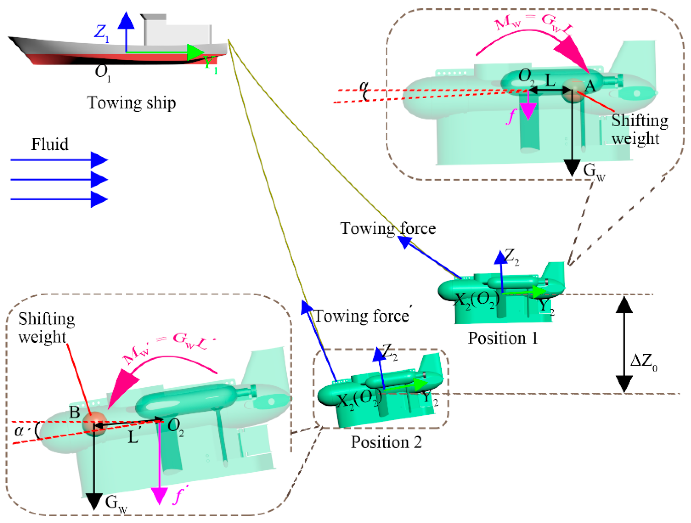
Figure 2, the shifting weight arranged in a watertight cabin is driven by a servo motor and moves along the longitudinal direction (Y2 direction) of the towed vehicle. The depth tracking control system can control the pitching angle of the towed vehicle by controlling the longitudinal position L of the shifting weight and longitudinal moment caused by the shifting weight at O2 to realize the submerged depth control of the towed vehicle. Specifically, as is shown in Figure 5, the whole towed vehicle is treated as a hydrofoil in the X2Y2 plane. When the shifting weight moves from point A to point B, the longitudinal moment formed by the shifting weight‘s gravity GW at O2 changes from MW to MW′ accordingly. Obviously, the change of the additional longitudinal moment results in the pitching angles of the towed vehicle increasing from α to α’; according to the wing theory, the lift acting on the towed vehicle increases from f to f’, accordingly. According to Newton’s second law, the towed vehicle will undergo an acceleration until it reaches a new balance position (Position 2) from the current position (Position 1). When the shifting weight moves from point B to point A, it is the other way round.
The control system works as described above. In this paper, the position L of the shifting weight was described in the coordinate system O2-X2Y2Z2 whose O2 is the center of gravity of the towed vehicle not including the shifting weight. The PID-based control system controls the speed of the shifting weight to control the longitudinal position of the shifting weight [
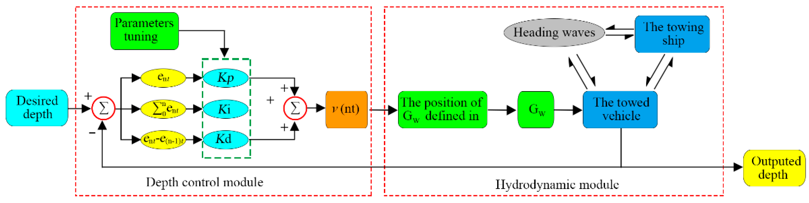
21]. In the control system, to avoid the damage caused by the collision between the shifting weight and other structures, limit positions of the shifting weight are defined. When the shifting weight oversteps the safety range, the longitudinal velocity of the shifting weight becomes zero until the system output makes the shifting weight return to the safety range. The longitudinal velocity v(nt) of the shifting weight can be written as:
v ( nt ) = { K p e n t + K i i = 0 n e i + K d ( e n t e ( n 1 ) t )                         0.4 L 0.4 0                                                     L 0.4 , o r     L 0.4
where Kp, Ki, and Kd are the PID parameters; en is the vertical position deviation, and L is the longitudinal position of the shifting weight defined in O2-X2Y2Z2.
Figure 6 shows the simulation flow of the control system in this paper as followings:
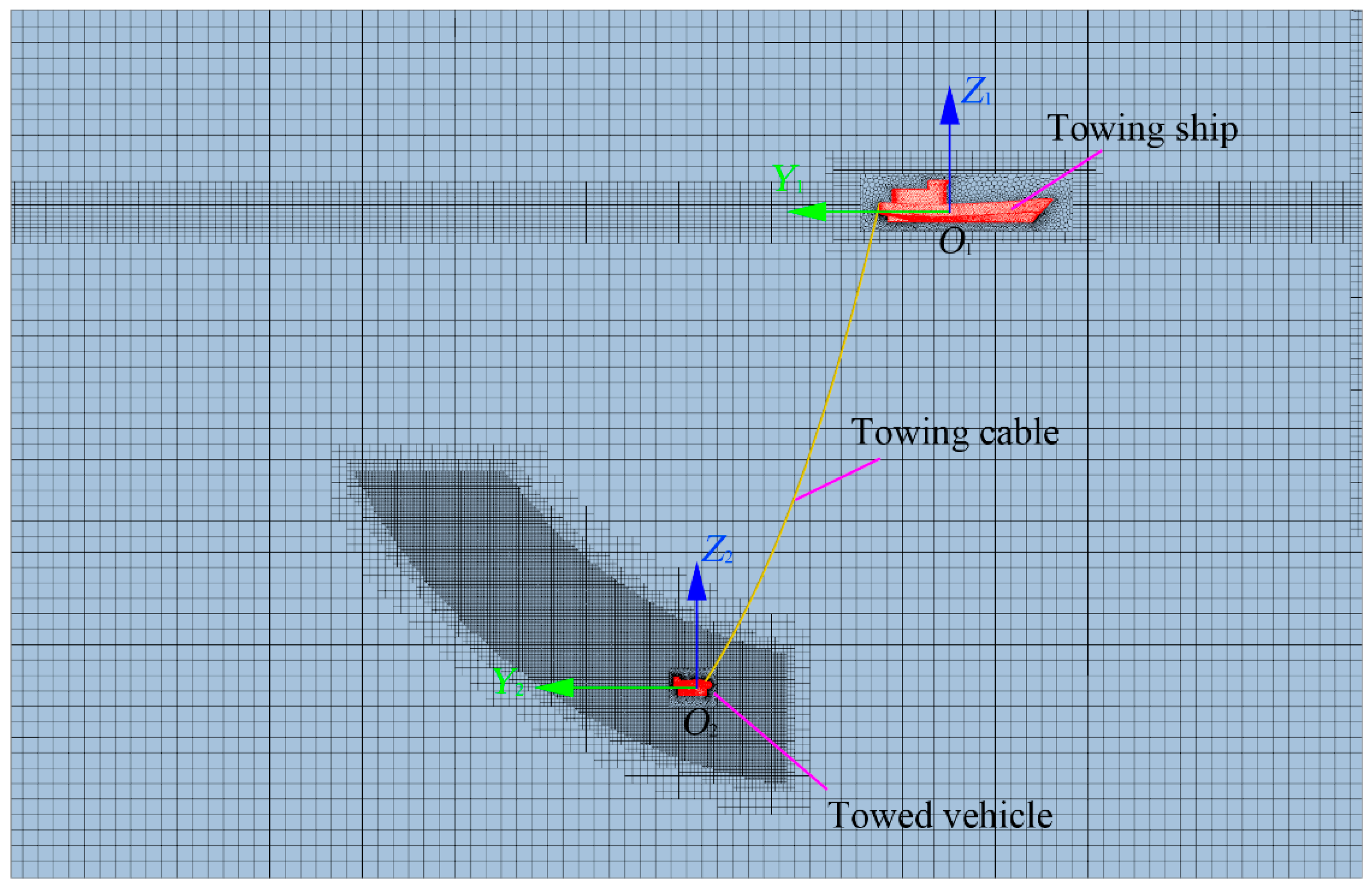
Step 1: Combined with Section 2.6, construct a control and CFD collaborative simulation system as shown in Figure 6. Create the computational domains shown in Figure 3 and Figure 4; create the towing cable model and connect the towing ship and the towed vehicle; establish the PID control equations and connect the control model with the CFD model.
Step 2: In the process of the PID parameters tuning, three possible PID parameters are given to the initial system, then a target depth is given; run the simulation, observe the deviation between the outputs submerged depth of the towed vehicle and the target one; adjust the PID parameters accordingly. Repeated this until an acceptable deviation occurs.
Step 3: Enter a desired submerged depth and start the simulation.

4. Validation of the Model on Hydrodynamic Simulation

For the purpose of verifying the effectiveness of the numerical method used in this paper, the numerical results of another towed vehicle were compared with its towing test data.
The simplified geometric model and the primary parameters of the towed system used to verify the feasibility of the numerical model are presented in Figure 7a and Table 2, respectively. The experiment was conducted in a towing tank with the dimension of 120 m (length) × 8 m (width) × 4.4 m (depth). A photo of the towing test at the towing velocity of 1.5 m/s is given in Figure 7b.
Figure 8a,b shows the numerical and experimental results of the steady-state submerged depths and pitching angle of the towed vehicle and the steady-state cable tensions at the upper endpoint of the towing cable at different towing speeds, respectively. The numerical submerged depths of the towed vehicle considered the correction of the installing position of the pressure sensor in the towing test; the cable tensions, the pitching angle, and the submerged depths were the average values of the time histories in the steady state. It can be seen that the steady-state submerged depths, pitching angle, and cable tensions by the numerical simulation were in good agreement with that of the towing test, which indicates that the numerical method in this paper was feasible to simulate the underwater towed system. In fact, the maximum relative deviation between the numerical results and the experimental results was less than 4%.

5. Simulation Results and Discussion

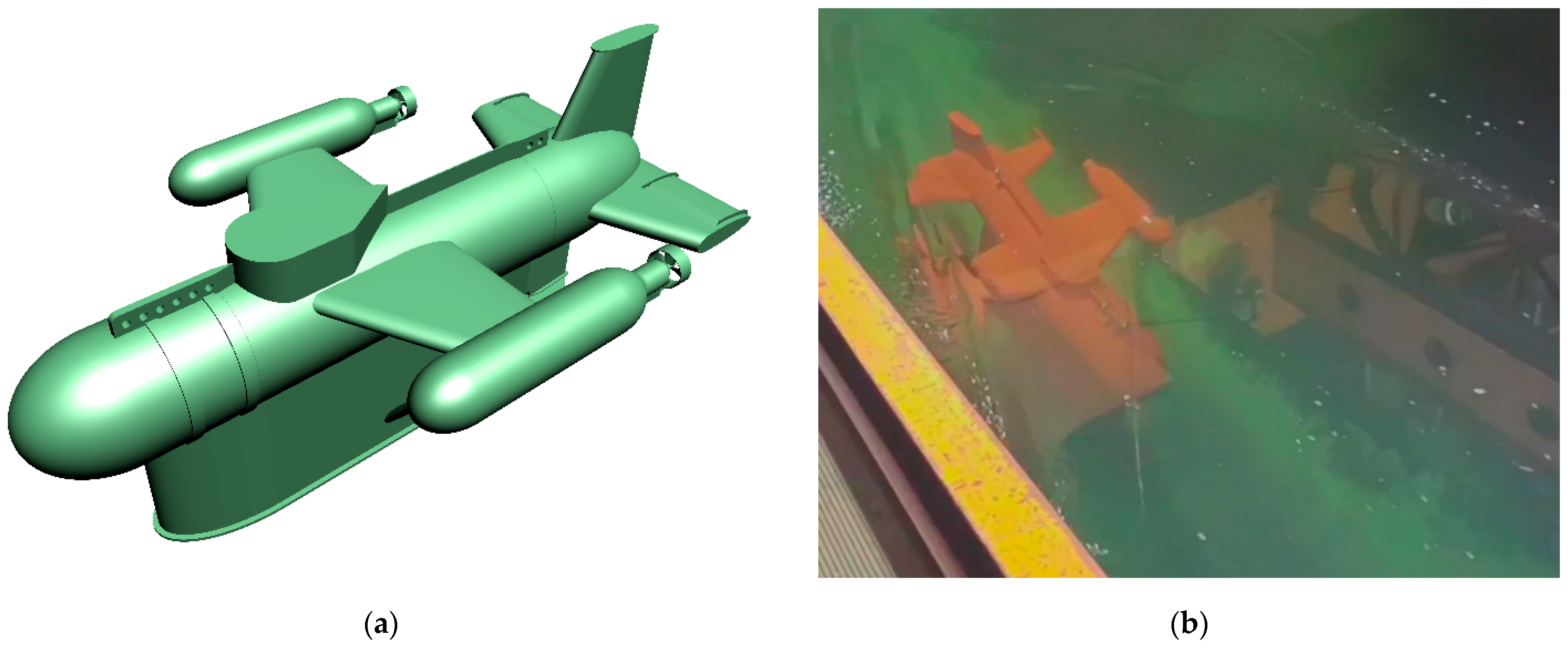
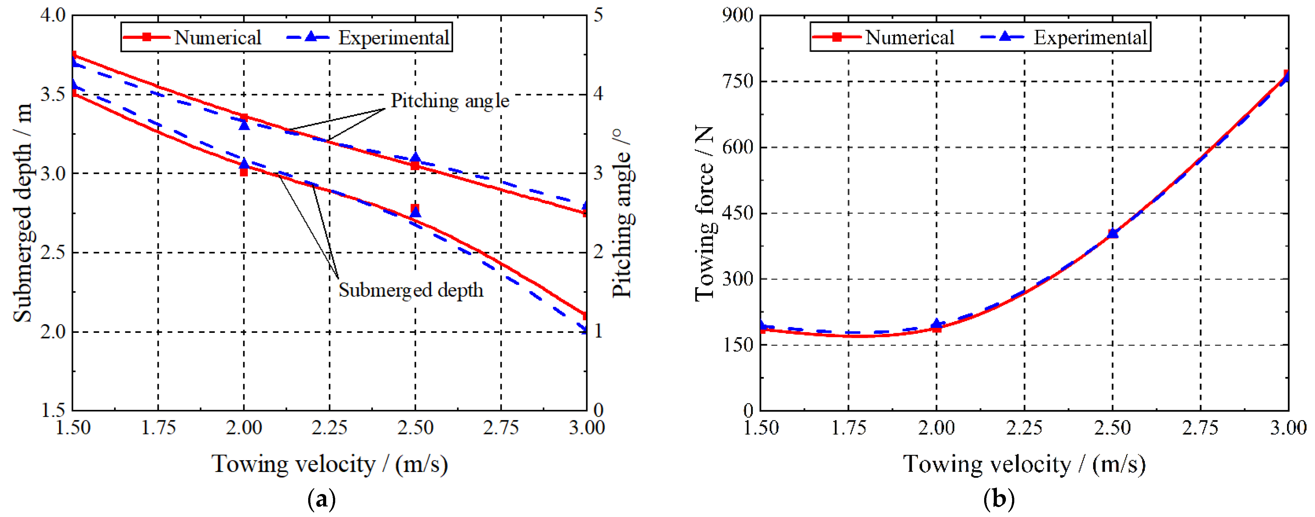
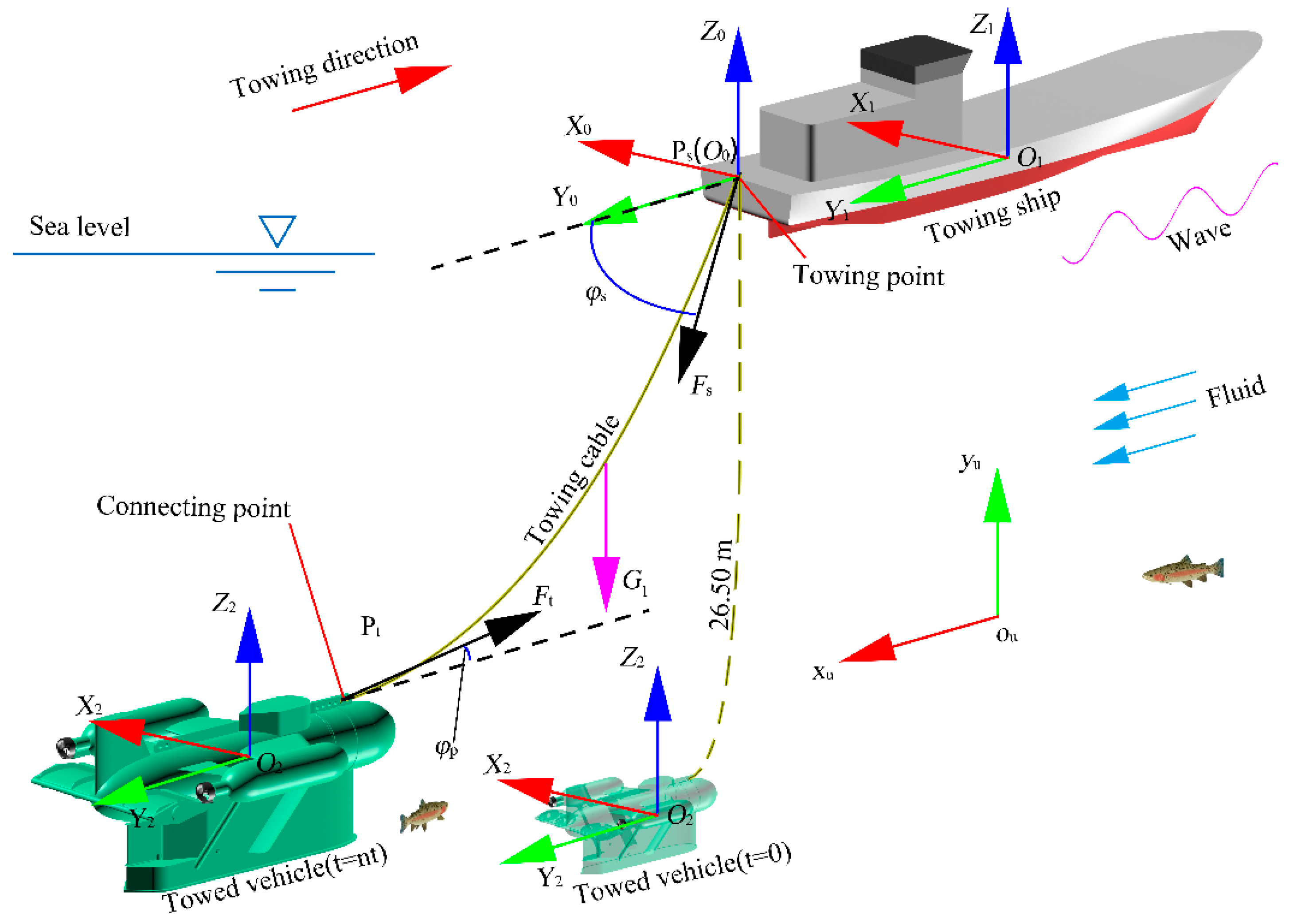
It can be seen from the results in Figure 8 that it was feasible to simulate the underwater towed system by the numerical method mentioned above. In this section, the vertical trajectory tracking in head waves of the complete towed system, as is shown in Figure 1, was numerically simulated. In the simulation, the wave height was 0.5 m, the wavelength was 36 m, and the forward speed was 5 kn; Kp = −0.045, Ki = −0.000015, Kd = −8.5. At t = 0 s, the towed vehicle was freely suspended in still water, and the towing cable drooped naturally; when 0< t ≤ 100 s, the shifting weight was held at L = 0 m, and the towed vehicle was towed uncontrollably until it reached a stable state; t > = 100 s, depth tracking control was initiated. There were three stages in the depth tracking control, that is, Stage I: tracked the target Z0 = −14.5 m in the period of 100 s< t ≤ 200 s; Stage II: tracked the target Z0 = −17.0 m in the period of 200 < t ≤ 300 s; Stage III: tracked the target Z0 = −18.0 m in the period of 300 s < t ≤ 400 s.
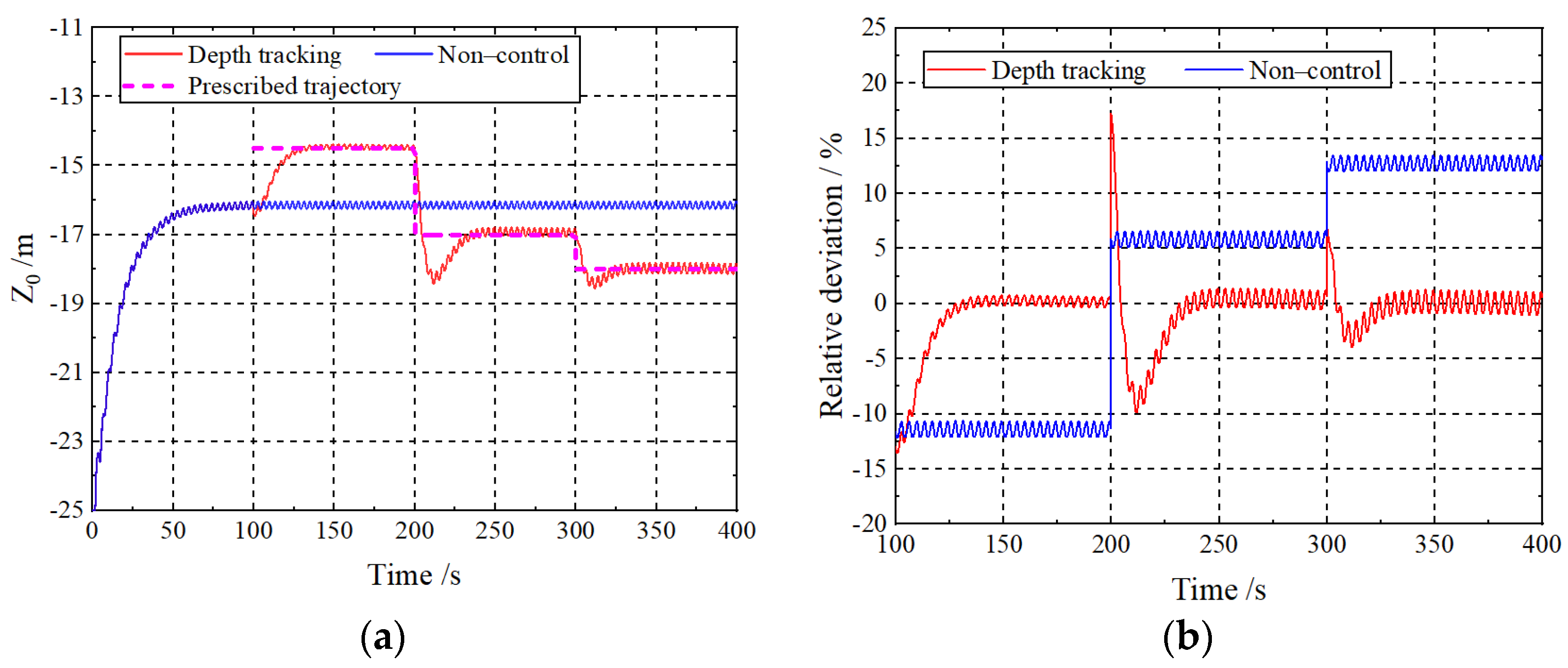
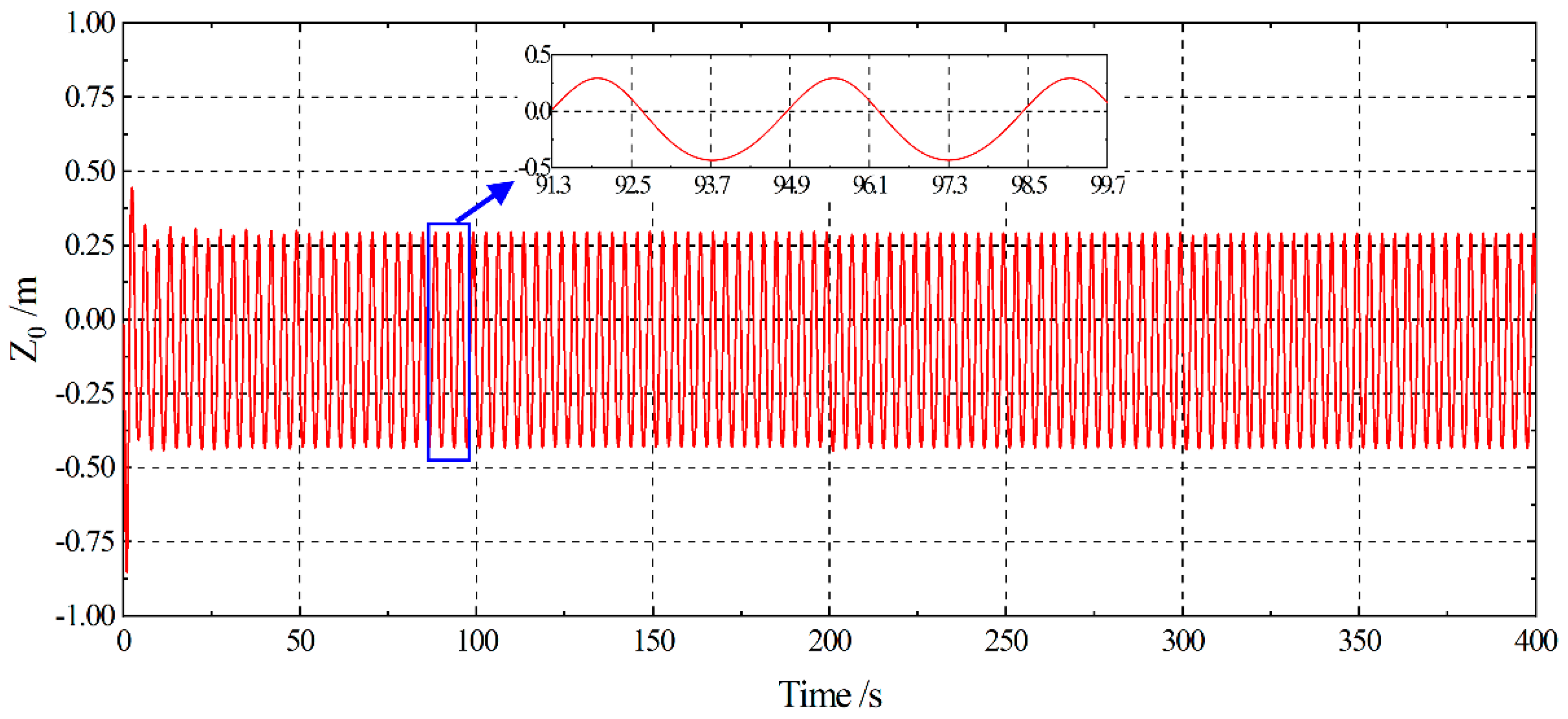
The numerical simulation results of the vertical trajectory tracking operation of the towed vehicle are given in Figure 9a,b. As shown in Figure 9a, the towed vehicle ascended rapidly from the original position to the target after the target Z0 = −14.5 m was given at t = 100 s, then vibrated stably around the target; similarly, as the new target Z0 = −17.0 m and Z0 = −18.0 m were given at t = 200 s and t = 300 s, respectively, the towed vehicle could also approach rapidly and vibrate stably around the new targets; as shown in Figure 9b, the steady-state deviation between the instantaneous vertical trajectory and the prescribed one of the towed vehicle was within 2.0%. The depth tracking system exhibited a good control robustness, and the target trajectory was tracked well in each stage. In addition, the vertical trajectory fluctuation of the towed vehicle under the depth tracking control system’s control was equivalent to the non-control condition, which indicated that the vertical trajectory saw no deterioration under the depth tracking control operation.
In addition, it can be seen from Figure 9 that the steady-state vertical oscillation amplitude of the towed vehicle changed with the change of the submerged depth. Specifically, that is, with the increase in the submerged depth, the vertical vibration amplitude of the towed vehicle increased. However, it is believed that the effects of wave on the motion of the underwater vehicle should be reduced with an increasing depth. In fact, when the towed vehicle was in a lower position, the angle between the almost-tight towing cable and the vertical direction was smaller, and the disturbance (vertical motion) of the towing point Ps would be more transmitted to the towed vehicle. It’s almost certain that the smaller the angle between the almost-tight towing cable and the vertical direction, the greater the disturbance transmitted to the towed vehicle. This was why the vertical oscillation of the towed vehicle did not decrease with the submerged depth, but increase.
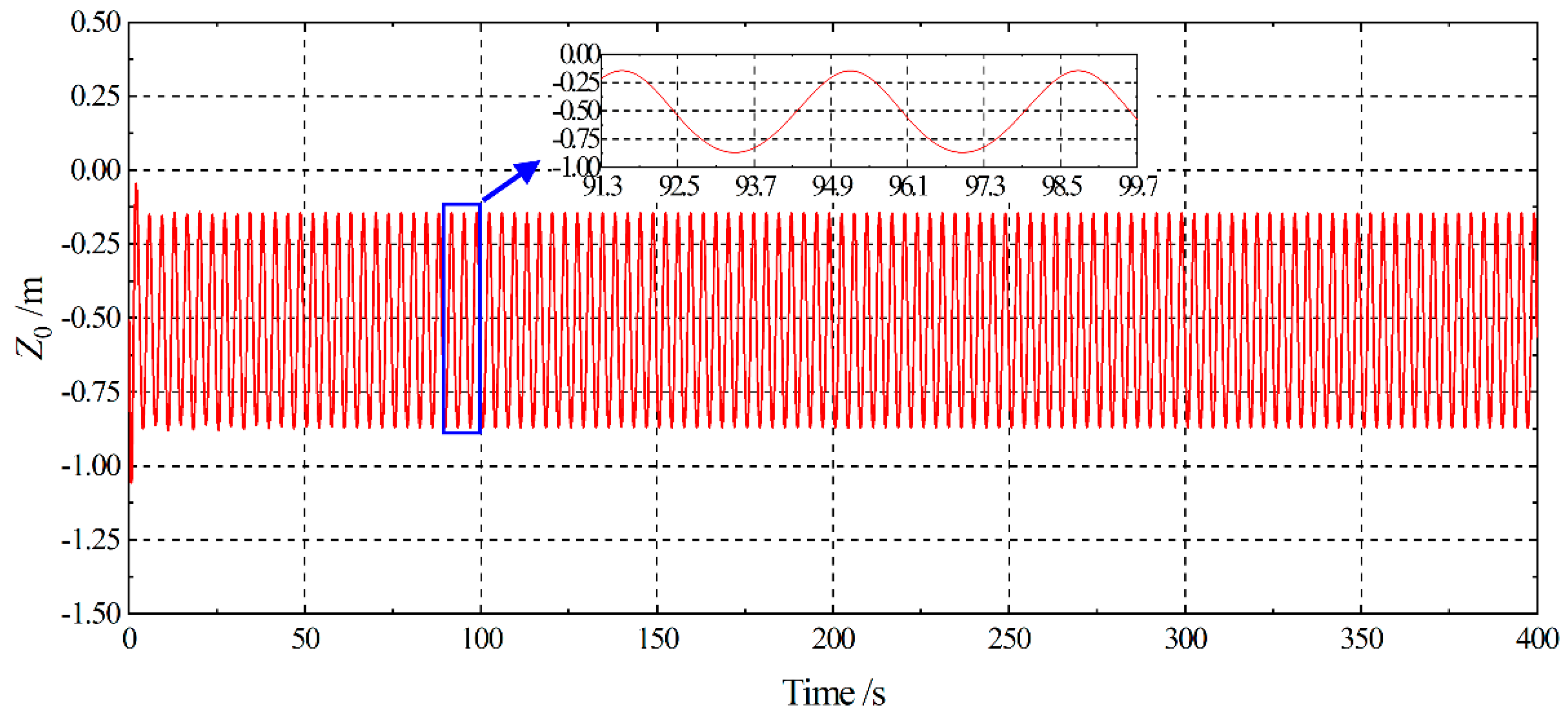
Figure 10 and 
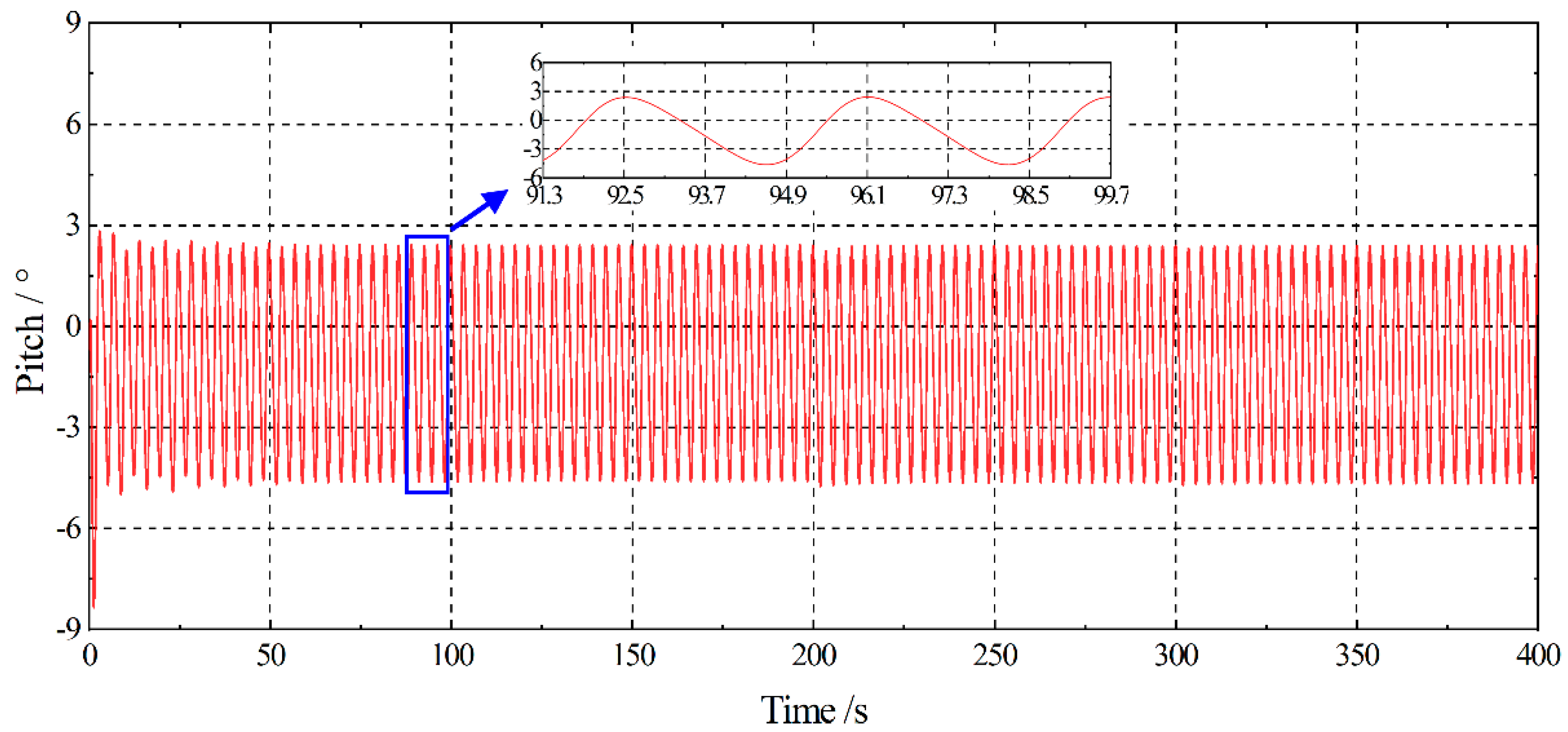
Figure 11 show the time histories of the vertical trajectory and the pitching angle of the towing ship, respectively; Figure 12 shows the vertical trajectory of the towing point Ps. It can be seen that under the influence of the head waves, the towing ship vibrated in the vertical plane with an amplitude of about 0.35 m and a period of about 3.6 s. At the same time, the pitching angle vibrated around −1° with an amplitude of about 3.0° and a period of about 4.0 s. The towing point Ps oscillated periodically around Z0 ≈ −0.1 m with an amplitude of about 0.35 m and a period of about 3.6 s. It can be seen from Figure 9 and Figure 10 that the oscillation of the towing ship was much greater than that of the towed vehicle; the depth tracking operation of the towed vehicle had no significant effect on the towing ship. Figure 13 shows the attitude of the towing ship and the towed vehicle when the towing ship was at different positions of the head waves. As shown, the numerical results in Figure 10, Figure 11, Figure 12 and Figure 13, the vertical position and pitching angle of the towing ship, the vertical position of the towing point Ps changed periodically with the towing ship moving from the trough to the crest of the head waves periodically. As the towing ship moved from the wave trough to the wave crest, the center of gravity of the towing ship ascended, the pitching angle decreased, and the towing point Ps moved upward. While the towing ship moved from the wave crest to the wave trough, the situation was in an exact opposite way.
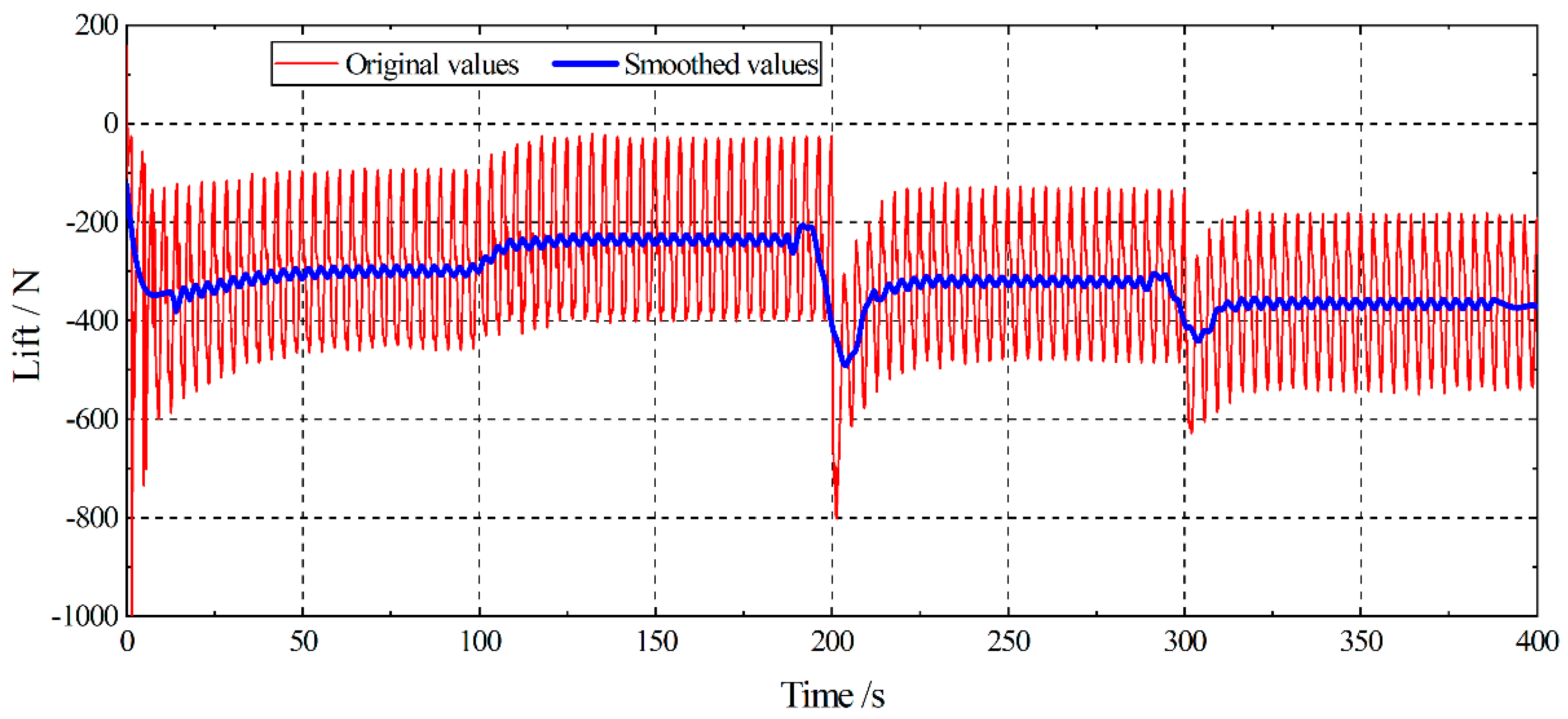
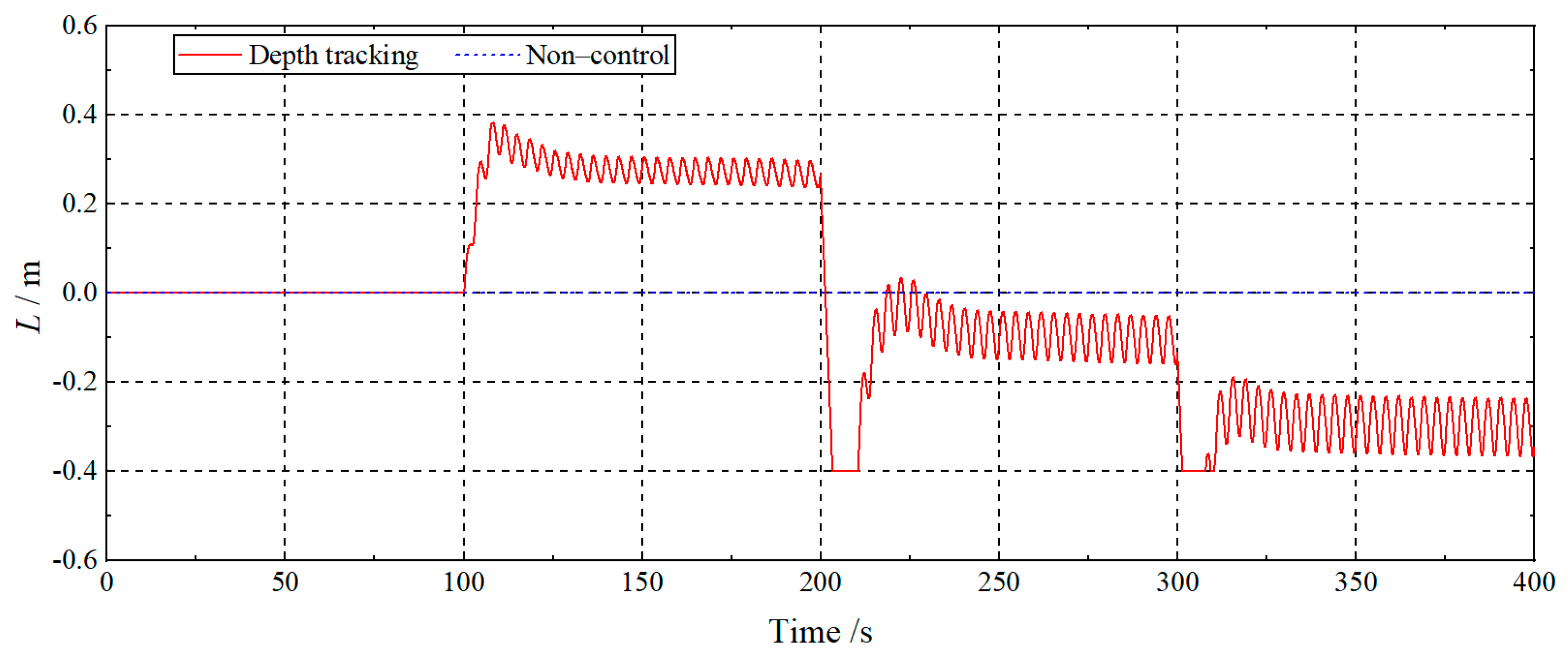
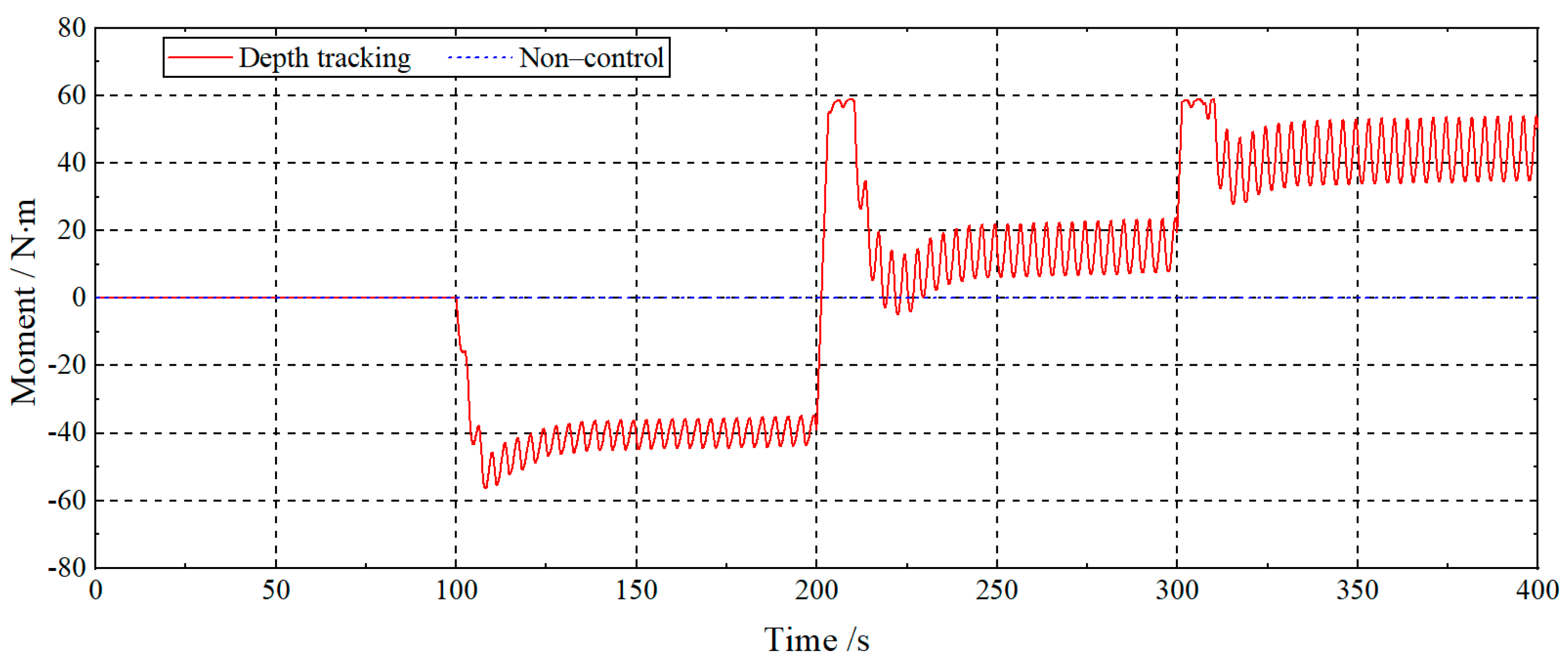
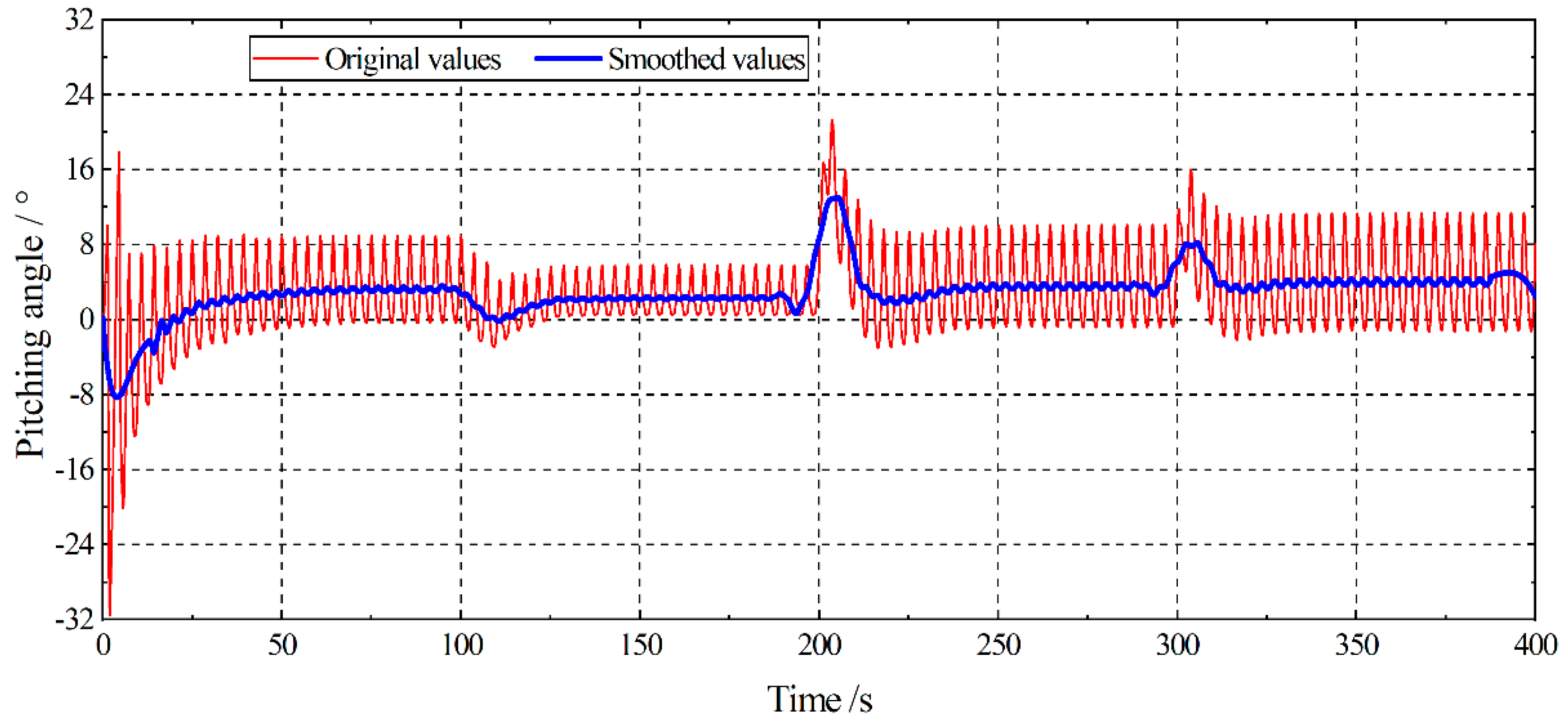
The depth tracking operation of the towed vehicle was closely related to the lift variation resulting in the change of the longitudinal position of the shifting weight. The time histories of the longitudinal position of the shifting weight, the longitudinal moment caused by the shifting weight at the O2, the pitching angle of the towed vehicle, and the lift on the towed vehicle are shown in Figure 14, Figure 15, Figure 16 and Figure 17, respectively. The 5th order Savitzky–Golay method was used to smooth the time histories of the pitching angle and the lift.
At the beginning of Stage Ⅰ, the vertical target Z0 = −14.7 m was above the instantaneous one, the shifting weight shifted backward (L > 0) rapidly and then vibrated stably around L = 0.3 m. A longitudinal moment that made the towed vehicle raise its head was formed at O2 as the shifting weight leaves away from O2. The time-mean down-pitch angle of the towed vehicle decreased, and the value of the downward lift decreased. The original equilibrium state was broken. The towed vehicle tracked the target trajectory and ascended rapidly.
In Stage II, the shifting weight moved forward (L < 0), the longitudinal moment at O2, which increased the down-pitch angle of the towed vehicle, reversed. The time-mean down-pitch angle of the towed vehicle increased, the value of the downward lift increased, and the towed vehicle descended.
Similarly, as the target trajectory further decreased to Z0 = −18.0 m in Stage III, the value of the downward lift further increased, and the towed vehicle continued to descend. In the above stages, the moment formed by the longitudinal position changed of the shifting weight, the pitching angle of the towed vehicle, and the lift all vibrated with the oscillation of the shifting weight. This was the result in the control system dynamically controlling the shifting weight forward or backward to maintain a small deviation under the interference of the head waves. The longitudinal velocity of the shifting weight driven by the servo motor determined the responsiveness of the control system, the result was that the vertical oscillation of the towed vehicle in the short period head waves persisted. However, as shown in Figure 9, the trajectory and attitude of the towed vehicle saw no deterioration due to the dynamic adjustment of the shifting weight.
Moreover, as mentioned in the analysis of Figure 9, when the towed vehicle was in a lower position, the angle between the towing cable and the vertical direction was smaller, and the disturbance of the towing point Ps would be more transmitted to the connected point Pt of the towed vehicle, so that the oscillation amplitudes of the vertical trajectory and the pitching angle of the towed vehicle increased with the increasing depth. Further, the increase in the vertical oscillation amplitude would inevitably lead to the increase in the deviation between the instantaneous vertical trajectory and the prescribed one. Under the control system’s operation, as shown in Figure 14, Figure 15 and Figure 16, the oscillation amplitude of the shifting weight increased with the increasing submerged depth resulting in the increase in the pitching angle oscillation amplitude of the towed vehicle.
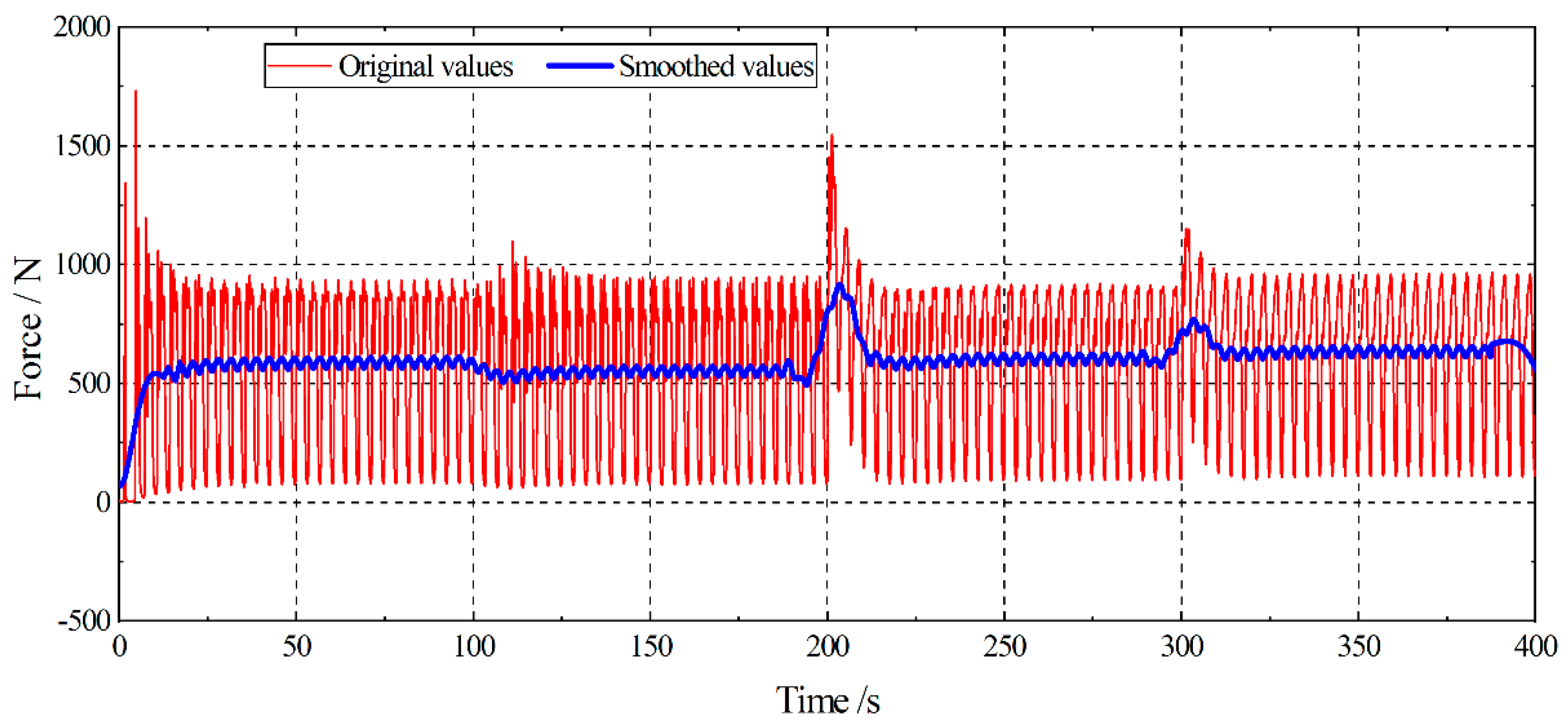
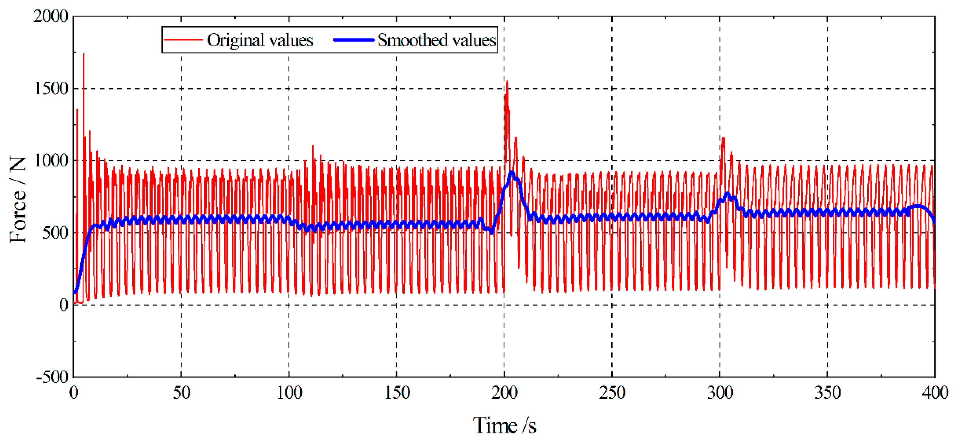
Figure 18 and Figure 19 show the time histories of the tension at the connecting point Pt and towing point Ps of the towing cable, respectively. In order to better describe the change of towing cable tension in different stages, the 5th order Savitzky–Golay method was used to smooth the time histories of the tension. As is shown in Figure 18 and Figure 19, the tension at the connecting point Pt and towing point Ps vibrated with the disturbance in different stages in a period of about 3.6 s; the tension increased suddenly when the control stages were switched; as a result of that, the angle between the towing cable and the resistance changed due to the vertical position changes of the towed vehicle, and the tension of the towing cable changed accordingly. Specifically, the steady-state tension at the connecting point Pt and the towing point Ps of the towing cable in Stage Ⅰ, whose instantaneous position was above that of the non-control towing operation, decreased; on the contrary, the steady-state tensions at the connecting point Pt and the towing point Ps of Stage II and Stage III increased, and the steady-state tension of Stage III was greater due to a lower position. In addition, the result in the influence of the weight of the towing cable, the time-mean tension at the towing point Ps was slightly larger than that at the connecting point Pt. In general, as the submerged depth increased resulting from the decrease in the lift on the towed vehicle, the tensions at the upper and lower ends of the towing cable increased, and vice versa. It was caused by the changes of the position and attitude of the towed vehicle under the control operation. On the one hand, when the towed vehicle was at a lower position, the lift acting on it was smaller. The towing cable needed an additional force to balance the additional vertically downward lift, which led to the increase in the cable tension. On the other hand, the lower position was caused by a smaller lift, which means a larger pitching angle and a larger upstream cross-sectional area. The resistance, which is closely related to the upstream cross-sectional area, was greater. The greater the resistance, the greater the cable tension.
Figure 20 presents the time-mean value of the steady-state parameters of the underwater towed system at different stages. It shows the relationship among the longitudinal position of the shifting weight, the pitching angle, and the vertical position of the towed vehicle, the lift, and the resistance on the towed vehicle, and the tension of the towing cable in a summarized way. It can be seen from Figure 20 that with the change of the longitudinal position L of the shifting weight at different depth tracking stages, the pitching angle and the vertical position of the towed vehicle, the lift and the resistance on the towed vehicle, and the tension of the towing cable also changed accordingly. As mentioned above, under an automatic control of the control system, from the free towing stage to Stage I, the shifting weight III moved backward, the longitudinal angle of the towed vehicle decreased, the lift increased, the towed vehicle moved up, the tension of the towing cable decreased, and the resistance decreased; from Stage Ⅰ to Stage II, it was the other way round. Further, from Stage II to Stage III, the shifting weight moved further forward, the pitching angle of the towed vehicle increased, the lift decreased, the towed vehicle descended, the tension of the towed line increased, and the resistance increased.

6. Conclusions

A numerical model combining the control system with the computational fluid dynamics (CFD) method based on the overset mesh technique was explored and constructed. The performance of the depth tracking control model of an underwater towed system composed of a towing ship, a towing cable, and a towed vehicle under the wave–ship interference condition was discussed. The depth tracking control model was based on the PID algorithm. The hydrodynamic characteristics of the towing ship and the towed vehicle in head waves were simulated by the computational fluid dynamics method. The towing cable was described by the quasi-steady-state catenary equations.
The simulation results showed that:
  • The depth tracking numerical simulation system of the underwater towed system proposed in this paper could simulate the depth tracking operation of the towed system.
  • The depth tracking system was robust when considering the interference of head waves. Under the system’s control, the towed vehicle could effectively track the target trajectory under the considered conditions. The deviation between the instantaneous trajectory and the target one was acceptable.
  • The amplitude of the instantaneous vertical trajectory of the towed vehicle under the system’s control was equivalent to that of the non-control condition, and the fluctuation was not worsened by the disturbance of the trajectory tracking control in the head waves.
  • The tension of the towing cable oscillated periodically under the influence of head waves in the trajectory tracking operations. In the case when the towed vehicle was at a higher position, the time-mean value of the tension of the towing cable was smaller, and greater by contraries.
However, more future work needs to be done. Although the feasibility of the numerical method used in this paper was verified by experiments, the motion control simulation method proposed could also effectively simulate the depth tracking operation; moreover, the numerical results also showed that the control strategy proposed exhibited a robustness under the wave–ship interference compared with the non-control operation. However, the simulation results could not realistically capture all the disturbance hydrodynamic effects and the real characteristics of the apparatus, such as the hydrodynamic of the towing cable, depth sensor, and servo motor performance. Therefore, as future work, if conditions permit, it is necessary to verify the effectiveness of the collaborative simulation of the computational fluid dynamics method and control system, as well as the performance of the control system through a maritime test; the hydrodynamic factors of a large-diameter towing cable should be considered in the hydrodynamic model in the future.

Author Contributions

Conceptualization, J.W.; methodology, X.Y.; software, X.Y.; validation, Q.L. and H.L.; formal analysis, X.Y.; investigation, X.Y.; resources, J.W.; data curation, X.Y.; writing—original draft preparation, X.Y.; writing—review and editing, J.W.; visualization, X.Y.; supervision, J.W.; project administration, J.W.; funding acquisition, J.W. All authors have read and agreed to the published version of the manuscript.

Funding

This research was funded by the National Key Research and Development Program (2018YFC1406602) of China, the National Natural Science Foundation (51979110) of China.

Institutional Review Board Statement

Not applicable.

Informed Consent Statement

Not applicable.

Data Availability Statement

The data presented in this study are available on request from the corresponding author.

Conflicts of Interest

The authors declare no conflict of interest.

References

  1. Liu, H.; Wang, Z.; Shan, R.; He, K.; Zhao, S. Research into the integrated navigation of a deep-sea towed vehicle with USBL/DVL and pressure gauge. Appl. Acoust. 2020, 159, 107052. [Google Scholar] [CrossRef]
  2. Tran, H.N.; Nhut Pham, T.N.; Choi, S.H. Robust depth control of a hybrid autonomous underwater vehicle with propeller torque’s effect and model uncertainty. Ocean Eng. 2021, 220, 108257. [Google Scholar] [CrossRef]
  3. Park, J.; Kim, N. Dynamics modeling of a semi-submersible autonomous underwater vehicle with a towfish towed by a cable. Int. J. Nav. Archit. Ocean Eng. 2015, 7, 409–425. [Google Scholar] [CrossRef] [Green Version]
  4. Nhut Thanh, P.N.; Tam, P.M.; Huy Anh, H.P. A new approach for three-dimensional trajectory tracking control of under-actuated AUVs with model uncertainties. Ocean Eng. 2021, 228, 108951. [Google Scholar] [CrossRef]
  5. Wu, J.M.; Xu, Y.; Tao, L.B.; Yu, M.; Dou, Y.Z. An integrated hydrodynamics and control model of a tethered underwater robot. China. Ocean. Eng. 2018, 32, 557–569. [Google Scholar] [CrossRef]
  6. Wu, J.M.; Chen, D.J. Trajectory following of a tethered underwater robot with multiple control techniques. J. Offshore Mech. Arct. Eng. Trans. ASME 2019, 141, 051104. [Google Scholar] [CrossRef]
  7. Curado Teixeira, F.; Pedro Aguiar, A.; Pascoal, A. Nonlinear adaptive control of an underwater towed vehicle. Ocean Eng. 2010, 37, 1193–1220. [Google Scholar] [CrossRef]
  8. Vu, M.T.; Choi, H.S.; Kang, J.; Ji, D.H.; Jeong, S.K. A study on hovering motion of the underwater vehicle with umbilical cable. Ocean Eng. 2017, 135, 137–157. [Google Scholar] [CrossRef]
  9. Cho, H.; Jeong, S.-K.; Ji, D.-H.; Tran, N.-H.; Vu, M.T.; Choi, H.-S. Study on control system of integrated unmanned surface vehicle and underwater vehicle. Sensors 2020, 20, 2633. [Google Scholar] [CrossRef] [PubMed]
  10. Vu, M.T.; Van, M.; Bui, D.H.P.; Do, Q.T.; Huynh, T.-T.; Lee, S.-D.; Choi, H.-S. Study on dynamic behavior of unmanned surface vehicle-linked unmanned underwater vehicle system for underwater exploration. Sensors 2020, 20, 1329. [Google Scholar] [CrossRef] [PubMed] [Green Version]
  11. Jung, D.W.; Hong, S.M.; Lee, J.H.; Cho, H.J.; Vu, M.T. A study on unmanned surface vehicle combined with remotely operated vehicle system. Proc. Eng. Technol. Innov. 2018, 9, 17–24. [Google Scholar]
  12. Vu, M.T.; Le Thanh, H.N.N.; Huynh, T.-T.; Thang, Q.; Duc, T.; Hoang, Q.-D.; Le, T.-H. Station-keeping control of a hovering over-actuated autonomous underwater vehicle under ocean current effects and model uncertainties in horizontal plane. IEEE. Access. 2021, 9, 6855–6867. [Google Scholar] [CrossRef]
  13. Vu, M.T.; Le, T.-H.; Thanh, H.L.N.N.; Huynh, T.-T.; Van, M.; Hoang, Q.-D.; Do, T.D. Robust position control of an over-actuated underwater vehicle under model uncertainties and ocean current effects using dynamic sliding mode surface and optimal allocation control. Sensors 2021, 21, 747. [Google Scholar] [CrossRef]
  14. Versteeg, H.K.; Malalasekera, W. An Introduction to Computational Fluid Dynamics: The Finite Volume Method; Wiley: New York, NY, USA, 1995; pp. 49–54. [Google Scholar]
  15. Tran, T.T.; Kim, D.H. The coupled dynamic response computation for a semi-submersible platform of floating offshore wind turbine. J. Wind. Eng. Ind. Aerodyn. 2015, 147, 104–119. [Google Scholar] [CrossRef]
  16. Zhang, W.; Jia, G.; Wu, P.; Yang, S.; Huang, B.; Wu, D. Study on hydrodynamic characteristics of AUV launch process from a launch tube. Ocean Eng. 2021, 232, 109171. [Google Scholar] [CrossRef]
  17. Liu, G.; Wang, M.; Xu, L.; Incecik, A.; Sotelo, M.A.; Li, Z.; Li, W. A new bionic lateral line system applied to pitch motion parameters perception for autonomous underwater vehicles. Appl. Ocean Res. 2020, 99, 102142. [Google Scholar] [CrossRef]
  18. Zhang, Y.; Yang, F.; Wang, D.; Jiang, X. Numerical investigation of a new three-degree-of-freedom motion trajectory on propulsion performance of flapping foils for UUVs. Ocean Eng. 2021, 224, 108763. [Google Scholar] [CrossRef]
  19. Amiri, M.M.; Esperanca, P.T.; Vitola, M.A.; Sphaier, S.H. An initial evaluation of the free surface effect on the maneuverability of underwater vehicles. Ocean Eng. 2020, 196, 106851. [Google Scholar] [CrossRef]
  20. Amiri, M.M.; Sphaier, S.H.; Vitola, M.A.; Esperanca, P.T. Viscosity effect on an underwater vehicle-free surface hydrodynamic interaction. Appl. Ocean Res. 2020, 104, 102365. [Google Scholar] [CrossRef]
  21. Xu, Z.Z.; Haroutunian, M.; Murphy, A.J.; Neasham, J.; Norman, R. A comparison of functional control strategies for underwater vehicles: Theories, simulations and experiments. Ocean Eng. 2020, 215, 107822. [Google Scholar] [CrossRef]
Figure 1. A schematic diagram of the underwater towed system.
Jmse 09 00874 g001
Figure 2. The geometric model: (a) the simplified towed vehicle; (b) the simplified towing ship.
Jmse 09 00874 g002
Figure 3. Computational domains and boundary conditions.
Jmse 09 00874 g003
Figure 4. Longitudinal cutaway view of the mesh.
Jmse 09 00874 g004
Figure 5. A schematic diagram of depth control.
Jmse 09 00874 g005
Figure 6. Simulation procedure for complete system.
Jmse 09 00874 g006
Figure 7. The towed vehicle for validation: (a) the simplified towed vehicle; (b) a photo of the towing test.
Jmse 09 00874 g007
Figure 8. Steady-state numerical and experimental results: (a) submerged depths and pitching angles; (b) towing forces.
Jmse 09 00874 g008
Figure 9. Time history of vertical trajectory of the towed vehicle: (a) instantaneous vertical trajectory; (b) relative deviation between the instantaneous vertical trajectory and the prescribed one.
Jmse 09 00874 g009
Figure 10. Time history of heave of the towing ship.
Jmse 09 00874 g010
Figure 11. Time history of the pitching angle of the towing ship.
Jmse 09 00874 g011
Figure 12. Time history of vertical trajectory of the towing point.
Jmse 09 00874 g012
Figure 13. The right view of the head wave and the towed system: (a) the towing ship is at the wave trough; (b) the towing ship deviates forward by half a wavelength from the wave trough; (c) the towing ship is on the wave crest; (d) The towing ship deviates forward by half a wavelength from the wave crest.
Jmse 09 00874 g013
Figure 14. Time history of longitudinal position of shifting weight.
Jmse 09 00874 g014
Figure 15. Time history of moment caused by the shifting weight.
Jmse 09 00874 g015
Figure 16. Time history of pitching angle of the towed vehicle.
Jmse 09 00874 g016
Figure 17. Time history of lift of the towed vehicle.
Jmse 09 00874 g017
Figure 18. Time history of tension at the connecting point.
Jmse 09 00874 g018
Figure 19. Time history of tension at the towing point.
Jmse 09 00874 g019
Figure 20. Mean value of steady-state parameters of the towed system in different stages.
Jmse 09 00874 g020
Table 1. Primary parameters of the underwater towed system.
ComponentsTowed VehicleTowing ShipTowing CableShifting Weight
ParameterLength (m)Width (m)Height (m)Mass in air (kg)Mass in water (kg)Length (m)Width (m)Height (m)Displace-ment (kg)Mass per unit length (kg/m)Length (m)Diameter (m)Added mass coefficientStiffness (N/m)Mass (kg)
Value or definition1.9711.240.999194.2117.16922.093867.970.0226.50.0050.210,00015
Table 2. Primary parameters of the underwater towed system for validation.
ComponentsTowed VehicleTowing Cable
ParameterLength (m)Width (m)Height (m)Mass in air (kg)Mass in water (kg)Mass per unit length (kg/m)Length (m)Diameter (m)Added mass coefficientStiffness (N/m)
Value or definition1.9711.20.999177160.023.70.0050.210,000
Publisher’s Note: MDPI stays neutral with regard to jurisdictional claims in published maps and institutional affiliations.

