Article

Model Simulation of M2 Internal Tide at the Mariana Double Ridges

1
College of Oceanic and Atmospheric Sciences, Ocean University of China, Qingdao 266100, China
2
Institute of Deep-Sea Science and Engineering, Chinese Academy of Sciences, Sanya 572000, China
3
South Marine Science and Engineering Guangdong Laboratory (Zhuhai), Zhuhai 519000, China
*
Author to whom correspondence should be addressed.
J. Mar. Sci. Eng. 2021, 9(6), 592; https://doi.org/10.3390/jmse9060592
Submission received: 27 April 2021 / Revised: 25 May 2021 / Accepted: 26 May 2021 / Published: 29 May 2021
(This article belongs to the Special Issue Advance in Circulation and Internal Wave Dynamics)

Abstract

:
In this study, M2 tidal energy and tide-induced mixing in the Mariana double ridges are investigated with a high-resolution three-dimensional non-hydrostatic numerical model and baroclinic energy budget analysis. The interference effect of the double ridges on the internal tide in the Mariana is examined by omitting either the eastern or the western ridge. Our results show that the baroclinic velocity on the sides of the interior facing slopes of the double ridges is larger than that on the other sides. In the double ridges, high values of dissipation reaching O (10−6 W kg−1) are accompanied by diapycnal diffusivity reaching O (10−1 m2 s−1), which is several orders of magnitude higher than the mixing of the open ocean. The bottom diapycnal mixing in the inner region between the two ridges is one order of magnitude larger than the mixing outside the ridges, indicating the important role of the interference of the double-ridge topography on the mixing in the Mariana Arc. Omitting either the eastern or the western ridge would have a significant impact on tide current, baroclinic energy flux and dissipation, and diapycnal mixing. The internal tide conversion, dissipation, and flux divergence are amplified by the double ridge topography, especially in the central part of the double ridges. Through energy budgets analysis, we conclude that the eastern ridge is the main source of the baroclinic tide in the Mariana double ridges.

1. Introduction

Vertical mixing is ubiquitous in the global ocean. It determines kinetic energy, heat energy, and material transport in the ocean, and is essential for maintaining ocean stratification and meridional overturning circulation. If there is no mixing in the ocean, the ocean will become dead water with only a thin, warm surface [1,2].
The input of external mechanical energy is the key to maintaining ocean mixing, including the input of wind energy at the surface and the internal tide generated by the ocean current and topography. However, most of the energy input by wind is dissipated in the upper ocean, and only a small part of the energy descends below the upper layer. The net work done by the wind on the ocean circulation does not meet the estimated deep-sea mixing budget [3,4]. Moreover, many studies indicate that the diapycnal diffusivity in abyssal ocean is an order of magnitude smaller than the global averaged diapycnal diffusivity suggested by Munk [1,5,6,7]. Munk and Wunsch [2] pointed out that in order to maintain the current strength of the oceanic thermohaline circulation, the average ocean mixing rate must be at least 10−4 m2 s−1, which means that there must be a strong mixing caused by a special mechanism in the ocean to support the normal thermohaline circulation of the ocean. Such a mechanism has been found to be the internal tide breaking, which plays an important role in the enhancement of diapycnal mixing.
In the global deep ocean, the energy converted from barotropic tide to internal tide is estimated to be 1 TW [8,9], which is about 1/3 of the total energy dissipated by the global ocean barotropic tide. It accounts for 1/2 of the energy required to maintain the global meridional overturning circulation [2]. Ledwell et al. [10] observed that the Atlantic ridge is a strong internal wave mixing zone with diapycnal diffusivity reaching 10−3 m2 s−1 at the bottom, and attributed this to the interaction between tidal current and the topography. Wang et al. [11] studied the tidal mixing in the South China Sea and found that the diapycnal diffusivity there can reach 102–101 W m2. Therefore, internal tide is the most important source of mechanical energy for deep-sea inter-surface mixing.
For internal tide generated over different topography, earlier researchers have established a model of internal tide generation on sharp topography [12,13,14,15,16]. Subsequently, Balmforth et al. [17] further developed the work of Llewellyn Smith and Young [16] and established a theoretical model of internal tide generation on arbitrary subcritical seabed topography and random seabed topography, and calculated the mixing of internal tides in critical conditions. Radko and Marshall [18] discussed the coupling effects of low-frequency vortices, air-sea interactions, and internal waves generated on the sea surface on mixing.
As the actual topography and stratification of the ocean are very complex, numerical simulation has become an important method for studying the generation and evolution of internal tides in some regions, such as ocean ridges [19,20,21], straits [22] and regional open ocean [11,23,24]. In recent years, the three-dimensional nonlinear, non-hydrostatic approximation Massachusetts Institute of Technology General Circulation Model (MITgcm) has also been widely used in the simulation of internal tides. Legg and Adcroft [25] used this model to study the reflection, shear instability, and mixing induced by internal waves generated over convex and concave critical topography. Nikurashin and Legg [26] simulated the dissipation mechanism of internal tide generated above rough topography with this model and found that the mixing at the bottom O (1 km) is maintained mainly by the energy transferred to small-scale internal waves through large-scale internal tide nonlinear wave-wave interaction. Buijsman et al. [21] applied this model to study the influence of the double ridge resonance on the internal tides at the Luzon Strait. Their results showed the enhancement of resonance is not only determined by the height of the ridge but also determined by the distance between two ridges. Wang et al. [11], considering the effects of internal tides generated locally and remotely, studied the tidal mixing at the Luzon Strait and the South China Sea by using this model simulation and energetics analysis. Their results showed that the internal tide radiated from the Luzon Strait is the main energy source for tidal dissipation in the South China Sea. Han and Eden [27] also used the MITgcm model to study the internal tides in the Luzon Strait. Combined with sensitivity experiments with different resolutions, they studied the M2 and K1 internal tides and compared their results with the linear theory result. Mazloff et al. [28] clarified the importance of remotely generated internal waves for the simulation of short time- and space-scale variability by comparing the simulation results of global models and regional models.
For the internal tide generated from the Mariana Arc, Zhao and D’Asaro [29] found that both the eastward and westward M2 tide radiating from the Mariana Arc and the West Mariana Ridge have isophase lines parallel to the arc that share the same center at 17° N, 139.6° E, which is also a focal point of the westward propagating M2 internal tides from the Mariana Arc. Kerry et al., [30] explored the mutual influence of internal tides between the Luzon Ridge and the Mariana Arc and found that remotely generated internal tides reduce the conversion rate of local internal tides. Without the influence of the internal tide from the Mariana Arc, the internal tide conversion rate of the Luzon Strait increased by 11%; without the influence of the internal tide from the Luzon Strait, the internal tide conversion rate of the Mariana Arc increased by 65%. Wang et al. [24] studied the radiation and mutual interference patterns of the M2 internal tide flux field for the whole Philippine Sea, considering internal tides generated from the Bonin Ridge and the Ryukyu Island Chain as well as the Luzon Strait and the Mariana Arc.
Former studies on the internal tides generated from the Mariana Arc mainly focused on its propagation dynamics, including the interaction with the Luzon Strait and other places. As we know, the Mariana Arc include double ridges, the eastern and western ridges. In this paper, we conduct a more detailed analysis of the internal tides generated from the Mariana double ridges, addressing these questions: (1) What impact does supercritical and subcritical topography at Mariana double ridges have on the M2 internal tide’s generation, dissipation, and induced mixing? (2) Is there constructive interference due to the double-ridge topography? (3) What are the magnitudes involved in (1) and (2)?
To address these questions, a high-resolution three-dimensional non-hydrostatic MITgcm numerical model is used to simulate M2 internal tide in the Mariana double ridges, which is the largest component of tide in the area. Based on the energy analysis method by Niwa and Hibiya [23], we discuss the mechanism of the generation, propagation, and dissipation of the internal tide in this area and analyze the internal tide energy budget there. Furthermore, we calculate dissipation rate and vertical mixing diffusivity caused by M2 internal tide in this area using a parameterization method. The interference is investigated by omitting the eastern or western ridge. The model setup and estimation methods are further explained in Section 2. Model results are illustrated and analyzed in Section 3. The paper is discussed and summarized in Section 4 and Section 5, respectively.

2. Methodology

The model used in this study is the MITgcm model, developed by the Massachusetts Institute of Technology [31]. The model is flexible for hydrostatic and non-hydrostatic formulations with adjoint capability, which enables modelers to simulate fluid phenomena over a wide range of scales and apply it to parameter and state estimation problems. In recent years, this model has been widely used in the simulation and research of internal tide generation, propagation, and dissipation on rough topography [11,22,32].

2.1. Model Setup

The model domain is configured to cover the eastern part of the Philippine Basin, the Mariana double ridges, and part of the Northwest Pacific Basin ranging from 4° N to 25° N in latitude and from 128° E to 150° E in longitude (Figure 1a). The model bathymetry is linearly interpolated from the General Bathymetric Chart of the Oceans (GEBCO_08) bathymetry data (http://www.gebco.net/ accessed on 20 April 2020) with a high resolution of 30 arcs. The horizontal grids of the model are designed as 1/24° × 1/24°. The water column is decomposed to 74 levels in the vertical direction with a thickness of 10 m near the surface, gradually increasing to 50 m in the upper 300 m, 100 m from 300 m to 5500 m, and then a constant thickness of 500 m from 5500 m to the bottom.
The initial temperature and salinity field of the model from the surface to 5500 m is derived from the World Ocean Database (http://wod.iode.org/SELECT/dbsearch/dbsearch.html/ accessed on 20 April 2020) and World Ocean Atlas (WOA18, https://www.nodc.noaa.gov/OC5/SELECT/woaselect/woaselect.html/ accessed on 20 April 2020). Its horizontal resolution is 1/4°×1/4° and the vertical depth to 5500 m is divided into 105 levels of unequal intervals that increase with depth. The temperature and salinity data below 5500 m is derived from World Ocean Database 2018 (WOD18) in which there was one temperature-salinity profile. The two datasets are coupled and interpolated by using linear interpolation into the 74 levels of the model to obtain the initial temperature and salinity field. The initial temperature and salinity field of the model varies with horizontal position above 5500 m, and is uniform below 5500 m.
Previous studies have shown that M2 tide is the most important component of tide in the Northwest Pacific [30,33,34]. Hence, only M2 tide is used to force the model in this study. The M2 tidal amplitude and phase are extracted from the Oregon State Tidal Inversion Software (OTIS) dataset for the Pacific Ocean with a horizontal resolution of 1/12° (http://volkov.oce.orst.edu/tides/PO.html/ accessed on 20 April 2020). The model applies M2 tidal component as a driving force on the boundary and sets a 0.5° sponge layer on the boundary to eliminate the artificial reflection. The model features a scheme that computes vertical viscosities and diffusivities above background values of 10−5 m2 s−1 by Thorpe sorting unstable density profiles [35]. The horizontal viscosity and diffusivity are 10−2 m2 s−1 and are constant in time. The bottom drag coefficient is set to 0.0025. The model was integrated for 60 days from an initial state with time steps of 90 s. It takes about 13 days for the model to reach a steady state. The time series of simulated results for days 19 and 20 are used for further calculation and analysis. To investigate the roles of eastern and western ridges on modulating internal tide in the target area separately, we run three cases under the same model setup except the different input topography for comparison. The first case runs as the base case with double ridges (named case DR). The second and third cases run with single eastern and western ridges (named cases SE and SW, respectively).

2.2. Model Validation

The internal tide is generated when the density-stabilized seawater driven by the barotropic tide flows through the dramatically changing terrain. Therefore, accurate simulation of barotropic tide is the premise of internal tide simulation. To ensure that, we compare our results of the simulated amplitude and phase of M2 barotropic tide with the OTIS data in the study area. Figure 2 shows that the model simulated amplitude and phase are consistent with the OTIS database. The correlation coefficient of amplitudes between the model and OTIS is 99.8%, while the phase is 82.4%.
In addition, observed surface elevation data was available at three sea level stations within the model domain (Figure 1a). They included two deep water stations (Stations 1 and 2) and a coastal station (Station 3) from the National Oceanic and Atmospheric Administration (NOAA) Center for Operational Oceanographic Products and Services (https://www.noaa.gov/ accessed on 20 April 2020). To compare the observed data with simulation results, this study uses the absolute RMS error, accounting for both amplitude and phase discrepancies, as described by Cummins and Oey [36]:
E = 1 2 ( A o 2 + A m 2 ) A o A m c o s ( G o G m )
where subscripts o and m denote observed and modeled amplitudes (A) and phases ( G ), respectively. Our model results are consistent with the observations at the two deep water stations with <0.06 m absolute RMS errors, which account for 4.7% and 10.7% of the observation, respectively (Table 1). However, the model has a poor performance at the coastal station, where the absolute RMS error is 0.037 m, which accounts for 33.6% of the observation. This may be attributed to the fact that the coastal station near Guam, where the true depth is 8 m, is greatly affected by shoaling effects [30]. On the whole, the comparison results indicate that the model has the ability to accurately simulate the M2 barotropic tide in the target area.

2.3. Estimation Method

Slope criticality is a nondimensional parameter that characterizes the regime of the internal tide generation, propagation, and dissipation. Using nondimensional parameters for criticality, topographic Froude number, and tidal excursion length, the slope criticality can be calculated as:
γ = | h | s = | h | ( N B ( r ) 2 ω tide   2   ω tide   2 f 2 ) 1 / 2
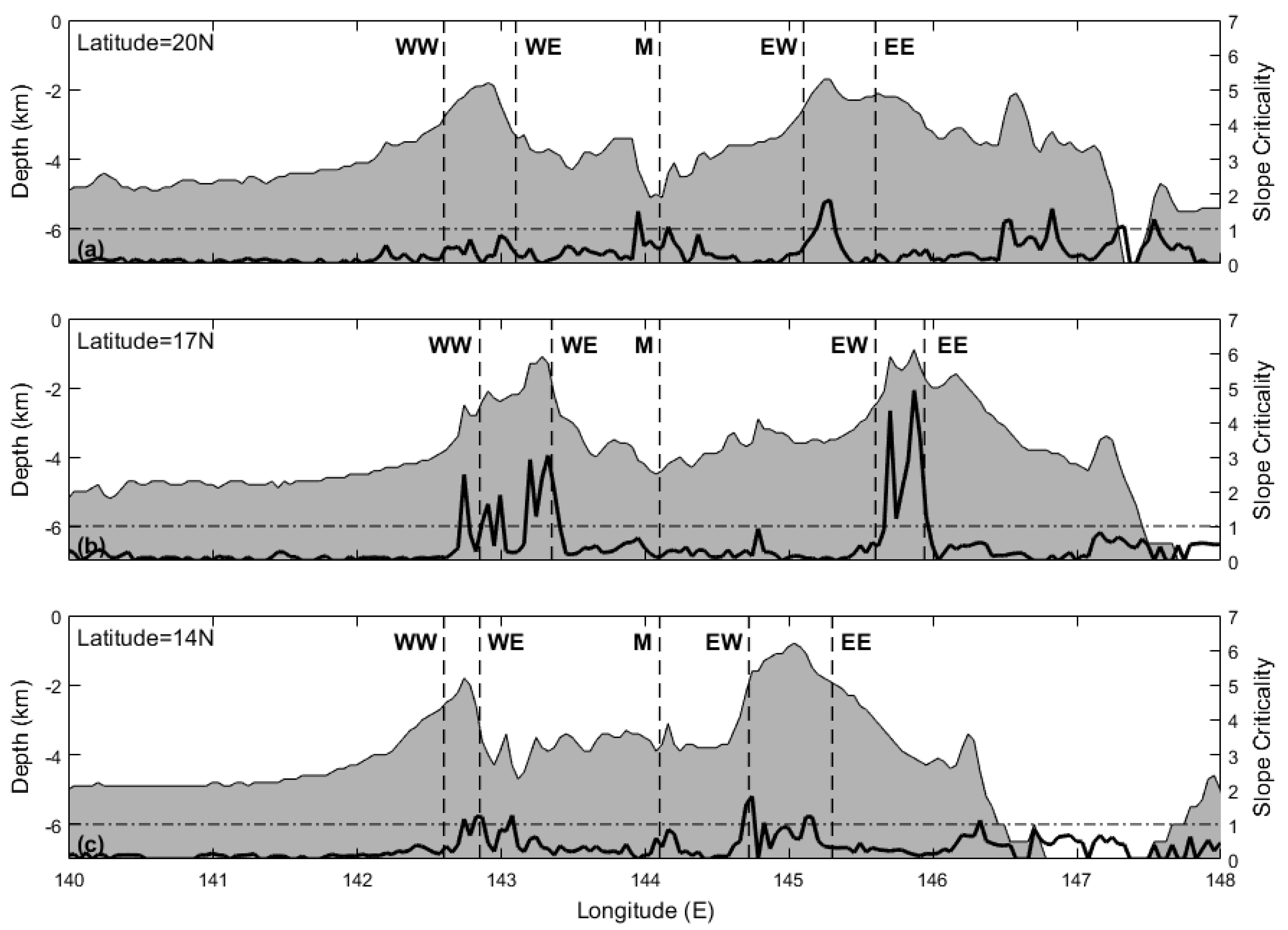
where f is the Coriolis frequency, N B ( r ) is the buoyancy frequency, ∇h is the topography slope, and ω tide   = 1 .41 × 10−4 s−1 is the semidiurnal frequency. If the slope is supercritical ( γ > 1), a great amount of energy will be reflected back, whereas if the slope is subcritical, presumably much of the energy continues and dissipates along the slope. Figure 3a shows that the eastern ridge has more supercritical condition than the western ridge, indicating different internal tide patterns between the double ridges.
Following Niwa and Hibiya [23], we use the depth-integrated baroclinic energy equation to calculate the internal tide energy:
T E N b c = h F b c + E b t 2 b c + A D V b c + D I S b c
T E N b c is the tendency of the baroclinic energy, which equals E b c t , and E b c is the depth-integrated baroclinic energy. F b c and E b t 2 b c are the depth-integrated baroclinic energy flux and the depth integrated conversion from barotropic to baroclinic energy, respectively. A D V b c and D I S b c denote the advection and the dissipation of baroclinic, respectively. It could be assumed that the tidal period mean of the depth integrated baroclinic energy is constant in a fixed area, and the advection of baroclinic energy,   A D V b c , is negligible. Then the tidal period mean of the depth-integrated dissipation rate of baroclinic energy can be calculated as:
D I S b c E b t 2 b c + h F b c
The symbol 〈〉 represents the tidal period mean. The depth-integrated conversion from barotropic to baroclinic energy, E b t 2 b c , and the divergence of the depth-integrated baroclinic energy flux, h F b c , can be calculated by the following two formulas:
E b t 2 b c = g H η ρ w b t d z
h · F b c = h · ( H η u p d z )
where η and H denote the sea level displacement and the mean water depth, respectively; w b t is the vertical velocity induced by the barotropic flow. The symbol means perturbation, so ρ , p , and u = ( u , v ) represent density perturbation, pressure perturbation, and horizontal baroclinic velocity, respectively. Wang [11] mentioned that the baroclinic energy dissipation, D I S b c , obtained by Equation (4) may include both the physical dissipation and biases due to numerical dissipation and other computation errors and thus could be somewhat overestimated. Despite this, Equation (4) is still a good approximation for estimating the baroclinic energy dissipation.

Dissipation Rate and Diapycnal Mixing

Following Mellor [37], the vertical velocity, w b t , can be obtained as:
w b t = U ( σ D x + η x ) + V ( σ D y + η y ) + ( σ + 1 ) η t
where U and V are the barotropic velocity in the x and y directions, respectively; D = H + η is the total sea water depth and σ is defined as σ = ( z η ) / D .
Following Nash et al. [38], the density perturbation, ρ , pressure perturbation, p , and horizontal baroclinic velocity, u , can be computed as follows. First, the density perturbation, ρ , is defined as:
ρ ( z , t ) = ρ ( z , t ) ρ ( z )
where ρ is the instantaneous density profile and ρ is the tidal period mean of ρ . Substituting the hydrostatic equation into Equation (6), the pressure perturbation can be obtained as:
p ( z , t ) = p s u r f ( t ) + z η ρ ( z ^ , t ) d z ^
where p s u r f ( t ) is the surface air pressure. It is inferred from the baroclinicity condition that the depth-averaged pressure perturbation must vanish:
1 H H η ρ ( z , t ) = 0
Then the pressure perturbation can be obtained as:
p ( z , t ) = 1 H H η z η g ρ ( z ^ , t ) z ^ + z η g ρ ( z ^ , t ) d z ^
The baroclinic velocity is defined as:
u ( z , t ) = u ( z , t ) u ( z ) u b t ( t )
where u is the instantaneous velocity, u is the tidal period mean velocity, and u b t ( t ) = ( U , V ) is the barotropic velocity, which is determined by the baroclinicity condition that the depth-averaged baroclinic velocity must vanish:
1 H H η u ( z , t ) d z = 0
Thus, the barotropic and baroclinic velocity can be calculated as:
u b t ( t ) = 1 H H η [ u ( z , t ) u ( z ) ] d z
u ( z , t ) = u ( z , t ) u ( z ) 1 H H η [ u ( z , t ) u ( z ) ] d z
Because of the lack of substantial micro-structure observations, the vertical distribution of energy dissipation due to the remotely generated internal tide remains unclear. Following the work of Wang et al. [11], we adopt a vertical function, F ( z ) , according to the LSJ02 parameterization given as:
F ( z ) = e x p [ ( D + z ) / ζ ] ζ [ 1 e x p ( D / ζ ) ]
where ζ is the vertical decay scale equals to 500 m, according to St. Laurent et al. [9]. Thus, the dissipation rate can be calculated as:
ϵ 1 ρ D I S b c F ( z )
Following the turbulent mechanical energy balance formulation of Osborn [39], the diapycnal mixing driven by the internal tide, both locally and remotely generated, can be calculated as:
k v Γ D I S b c F ( z ) ρ N 2 + k 0
where Γ is the mixing efficiency, which is taken to be the value of 0.2, according to the work of Osborn [39], k 0 is the background diffusivity with the value of 1 × 10⁻⁵ m2 s−1, and N 2 is the squared buoyancy frequency.

3. Results

3.1. The Barotropic Tidal Energy and Baroclinic Tidal Current

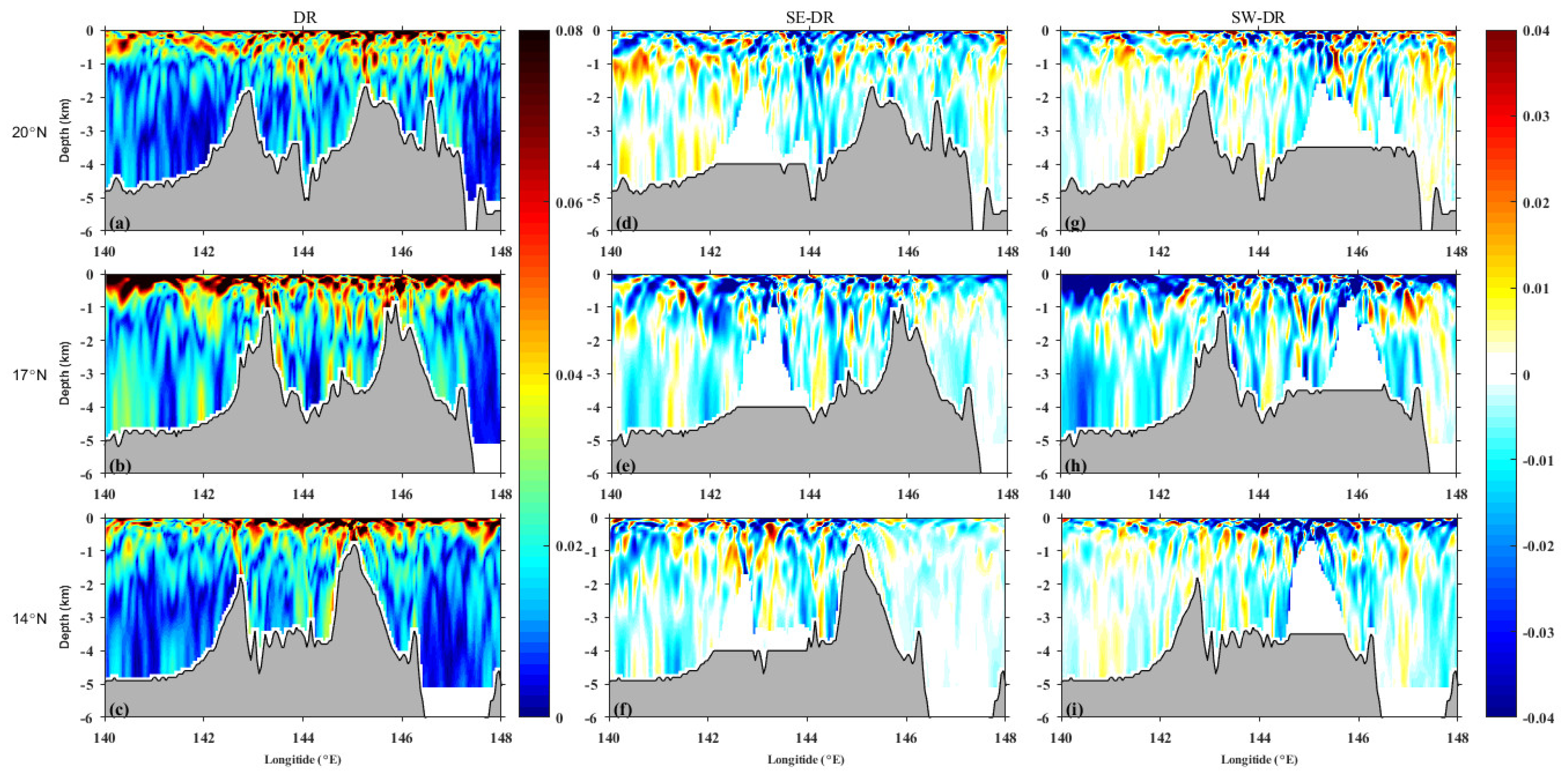
Figure 3b shows the M2 barotropic tidal energy flux at the Mariana double ridges. Similar to previous studies [24,30], the barotropic tidal energy enters the model domain from the east side. After flowing through the Mariana double ridges, the propagation direction of the barotropic tidal energy shifts north-westward. The propagation direction of the barotropic tide shifts almost 90° after flowing through the southernmost point of the eastern ridge, probably because of the wave refraction and the theory of flow around the cylinder. To illustrate spatial variation of baroclinic current at the double ridges under the three cases, the horizontal velocity tidal ellipses along three zonal sections at 20° N, 17° N, and 14° N are plotted in Figure 4. It can be seen that the vertical distribution of the baroclinic tidal ellipses is highly inhomogeneous. The elliptical characters of the three cases have something in common. Firstly, as the depth increases, the tidal current ellipses first decrease and then increase. The minimum baroclinic tidal current occurs at about 2200 m. Secondly, the baroclinic tidal current ellipses change significantly above steep topography. Thirdly, the ellipses’ major axes in three cases are all in an east-west direction. Fourthly, the tidal current ellipses along 17° N are larger than the other two latitudes. Comparing the three cases, we find that removing one ridge will decrease the baroclinic tidal current at all three latitudes. However, tidal currents in the SE case are larger than those in the SW case, which indicates that the eastern ridge contributes more to the baroclinic current. In order to better analyze the spatial distribution of baroclinic flow, we calculate the depth-integrated internal tidal energy flux in the next subsection.

3.2. Baroclinic Energy Flux

The depth-integrated baroclinic energy flux of three cases is calculated as:
F b c = H η u p d z
Results show that there are several strong baroclinic energy “streams”, indicated by the red zones in Figure 5a. One eastward stream is in the northern part of the Mariana double ridges, another stream propagates eastward from the southern part of the eastern ridge at about 15° N~17° N, and a third stream propagates westward from the central part of the western ridge at about 16° N~18° N. This is consistent with the observation results of Zhao and E. D’Asaro [29] and the simulation results of Kerry et al. [30] in which energy flux focused near 17° N with a peak of energy near 140° E. In most of the study area, the baroclinic energy flux is lower than 2 kW m−1, while those several streams of strong baroclinic energy flux can reach 6 kW m−1. The strongest energy flux can reach 12 kW m−1. The baroclinic energy flux is reduced under the SE case, with similar pattern with the DR case (Figure 5b). However, it declines largely under the SW case (Figure 5c), and the strong “streams” at 15° N~18° N vanish, indicating that the eastern ridge is the main source of the baroclinic energy at the Mariana double ridges.

3.3. Amplitude and Phase of Internal Tide Current

Here, we apply the harmonic analysis method to calculate the amplitude (Figure 6) and phase (Figure 7) of the internal tide zonal velocity at the Mariana double ridges under the three cases because zonal current is the main component of internal tidal current (Figure 5). Figure 6a–c show that the largest amplitude occurs in the upper layer and as the depth increases, the amplitude first decreases and then increases near the bottom, which is consistent with previous observation [35,40]. It can be seen that the baroclinic velocity along 17° N is generally larger than the velocity along the other two latitudes. This is probably because there is more supercritical topography along 17° N (Figure 8). The propagation of the M2 internal tide is characterized by beams emanating from the crests and peaks of the topographic features, as the locally enhanced baroclinic currents in the picture shows. In addition, we can see that the internal tide reflects between the sea surface and the seabed.
The slope criticality (Figure 3a) shows that, when going from shallow to deep water, the topography changes from supercritical to subcritical. The supercritical topography causes the internal tide’s scattering after generation. When the energy is reflected back to the sea surface, the change of the buoyancy frequency with depth makes the propagation trajectory of the reflected energy bend to a certain extent. For ridges with near-critical or supercritical topography, internal waves can form high modes on the back of the ridge. However, with the active intervention of internal wave in high modes, destructive interference occurs between waves of different modes [32]. This leads to the changes of water velocity beam, which becomes weaker and wider as it propagates away from the ridge and reflects between the sea surface and the seabed. As shown in Figure 6, the energy beam is obviously weakened and broadened due to high-mode destructive interference from reflection between the sea surface and the seabed.
Figure 6d–f shows the result of subtracting the amplitudes of the DR case from the SE case along the three sections. Negative/positive values mean the amplitudes are smaller/larger in the SE case. Figure 6g–i shows the same result but for the SW case. The amplitudes are significantly reduced in the SW and SE cases, and its reduction occurs near the surface and in the inner region, mostly between the two ridges. This indicates that removing a ridge will greatly affect the amplitude of baroclinic velocity in the inner region between the two ridges. Moreover, the decline of amplitude is greatest at 17° N in the SW case, which is consistent with the analysis in the last section that the eastern ridge is the main source of the internal tide. However, there are points at which the amplitudes in the two single ridge cases are greater than in the double ridge case. From the pattern of these points, we believe that this occurs mostly due to the phase change of the internal tide, which shifts the position where the maximum amplitude occurs. For the SE case, the amplitude on the east side of the ridge does not change much, however the amplitude changes significantly at all longitudes in the SW case. This means that omitting the western ridge has little effect on the east side of the eastern ridge, while omitting the eastern ridge affects the whole region.
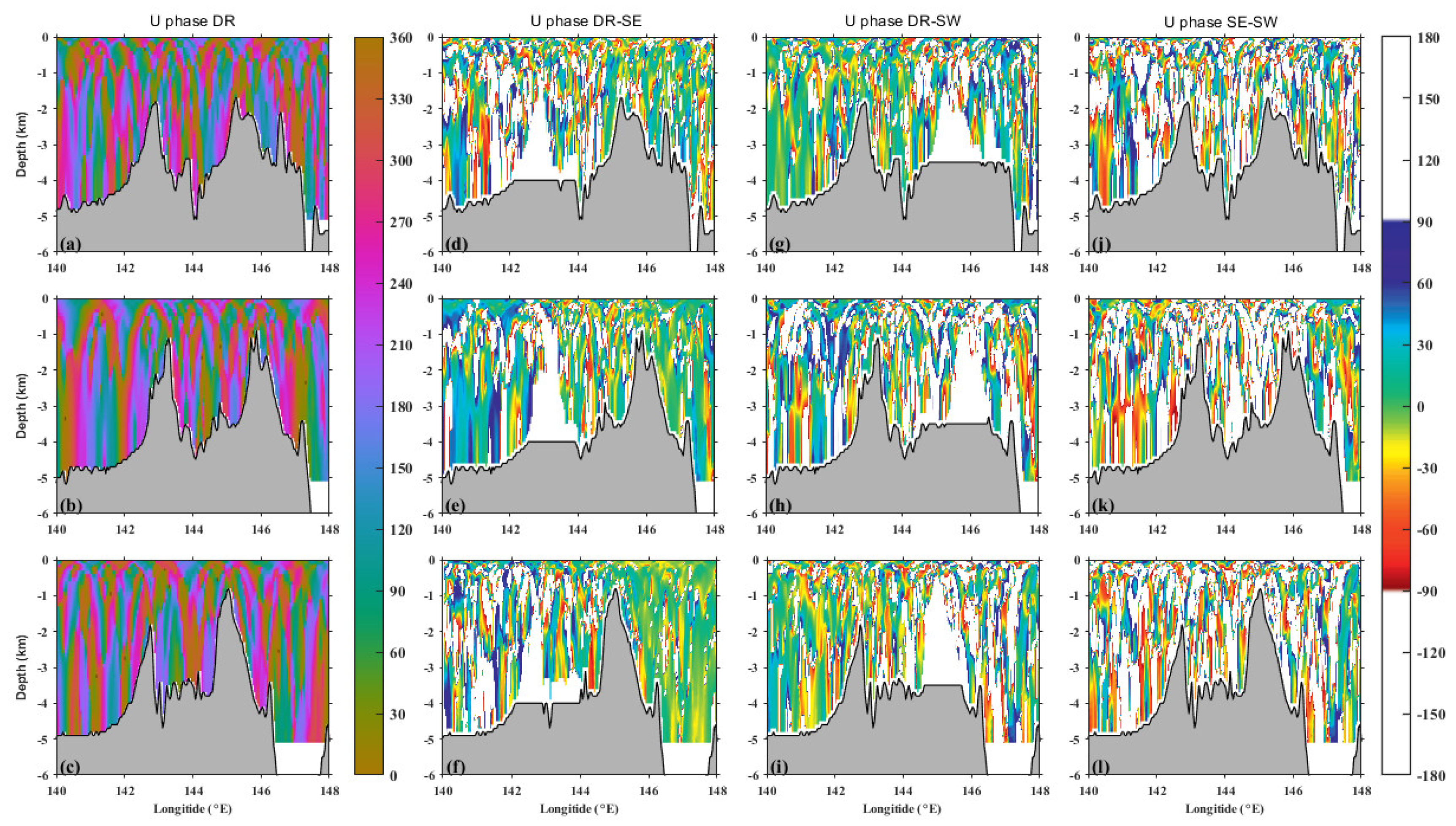
Figure 7 shows the phases of zonal velocity as Figure 6 under three cases along the three sections. The mutual interference can be clearly seen from Figure 7a–c. The clearer phase on the west side at 17° N (Figure 7b) also indicates that the internal tide energy will converge here, which is consistent with the previous result that the M2 internal tide converged at this latitude. The phase difference between the DR case and the SE case shows that omitting the western ridge hardly influences the phase at the east side of the eastern ridge (Figure 7d–f). However, the phase difference between the DR case and the SW case indicates that omitting the eastern ridge not only influenced the phase at the east side but also slightly influenced the phase at the west side of the western ridge (Figure 7g–i). Among the three latitudes, the west side of 17° N is most affected. The baroclinic tidal energy converged at 17° N is mainly caused by the eastern ridge, as Figure 5b,c shows.
Figure 7j–l illustrates the phase difference between the SE case and the SW case. Note that only the phase difference between −90° and 90° are shown, which indicates that the velocity due to the wave fields from both ridges are in phase. It can be found that phase difference occurs along several narrow beams that connect subridges of the eastern and western ridges, indicating that the velocities due to the wave fields from both ridges are partly in phase. Compared with the result from Buijsman et al. [22], we find that the semidiurnal tide in the Mariana double ridges is less in phase than the semidiurnal tide in the Luzon double ridge, leading to lee waves and smaller velocities.

3.4. Temporal Variation of Baroclinic Current

To explore the temporal variation of baroclinic current induced by M2 tide, we chose 15 stations for comparison, with five stations in each of the three sections along 20° N, 17° N, and 14° N, as shown in Figure 8. For the five stations in each latitude, the first two stations are at the western and eastern slopes of the western ridge (named WW and WE), the last two stations are at the western and eastern slopes of the eastern ridge (named EW and EE), and the third station is located between the two ridges (named M). In the following, we will merely discuss the zonal component of baroclinic velocity along the three sections and the time dependent velocity at the 15 stations because the patterns of the meridional component are similar and small.
The time variations of zonal baroclinic velocity at 15 stations along three latitudes under three cases are shown in Figure 9. From the vertical structure of time dependent velocity, we can see that at some stations the velocity tilts down with time and at other stations the velocity tilts up with time. The velocity that tilts down with time means the internal tide propagates downward, while the velocity that tilts up with time indicates that the internal tide propagates upward. Another feature is that the time dependent velocity pattern becomes more vertical under the depth of 2.0 km, meaning that, under this depth, the internal tide propagates mainly in a vertical direction due to weaker stratification in deep water.
Specifically, we can see that the magnitudes of baroclinic velocity at the M station are generally smaller than at the other stations under DR case (upper panel in Figure 9). This is because the M stations are located between the two ridges where the bottom topography is relatively flat. Moreover, the interference of baroclinic tide generated from two ridges leads to a chaotic velocity structure at the ravine. For example, its vertical structure has a clear boundary at about 2000 m and 3300 m at 20° N where a subridge on the west side of the M station with a depth of about 3300 m exists (Figure 8a). Meanwhile the water depth of the eastern ridge and western ridge is about 2000 m at this latitude. Therefore, the upper boundary at about 2000 m is affected by the general topography, while the lower boundary at about 3300 m is affected by the local topography. In addition, the velocities at the facing sides (i.e., the EW and WE stations) are generally larger than those at the back sides of the double ridges (i.e., the WW and EE stations), indicating a constructive internal tide interference between the two ridges.
In order to better show the change of baroclinic velocity, we calculated the average baroclinic velocity at the ravine of the double ridges of three cases. The average baroclinic velocity in the double ridge case is 0.051 m/s, while the average baroclinic velocity in the single east ridge case and single west ridge case is 0.041 m/s and 0.037 m/s, respectively, indicating that the baroclinic velocity is significantly reduced in single ridge cases. We can also see from Figure 9 that the velocities at the ravine of the double ridges (i.e., the EW, M, and WE stations) are weakened significantly under cases SE and SW compared with case DR. This is consistent with the suggestion that there is a constructive internal tide interference between the two ridges. At the middle of the ravine (i.e., the M station), the vertical structure of baroclinic velocity under the SE case is less complicated than that under the DR case, while it is slightly more complicated under the SW case than under the DR case, especially at 17° N and 14° N. We think this is caused by two reasons. Firstly, the lack of strong internal tide generated from the eastern ridge results in smaller baroclinic current at the ravine. Secondly, the interference between the locally generated baroclinic tide and the internal tide generated from the western ridge leads to a chaotic vertical structure of the baroclinic current.

3.5. Conversion Rate

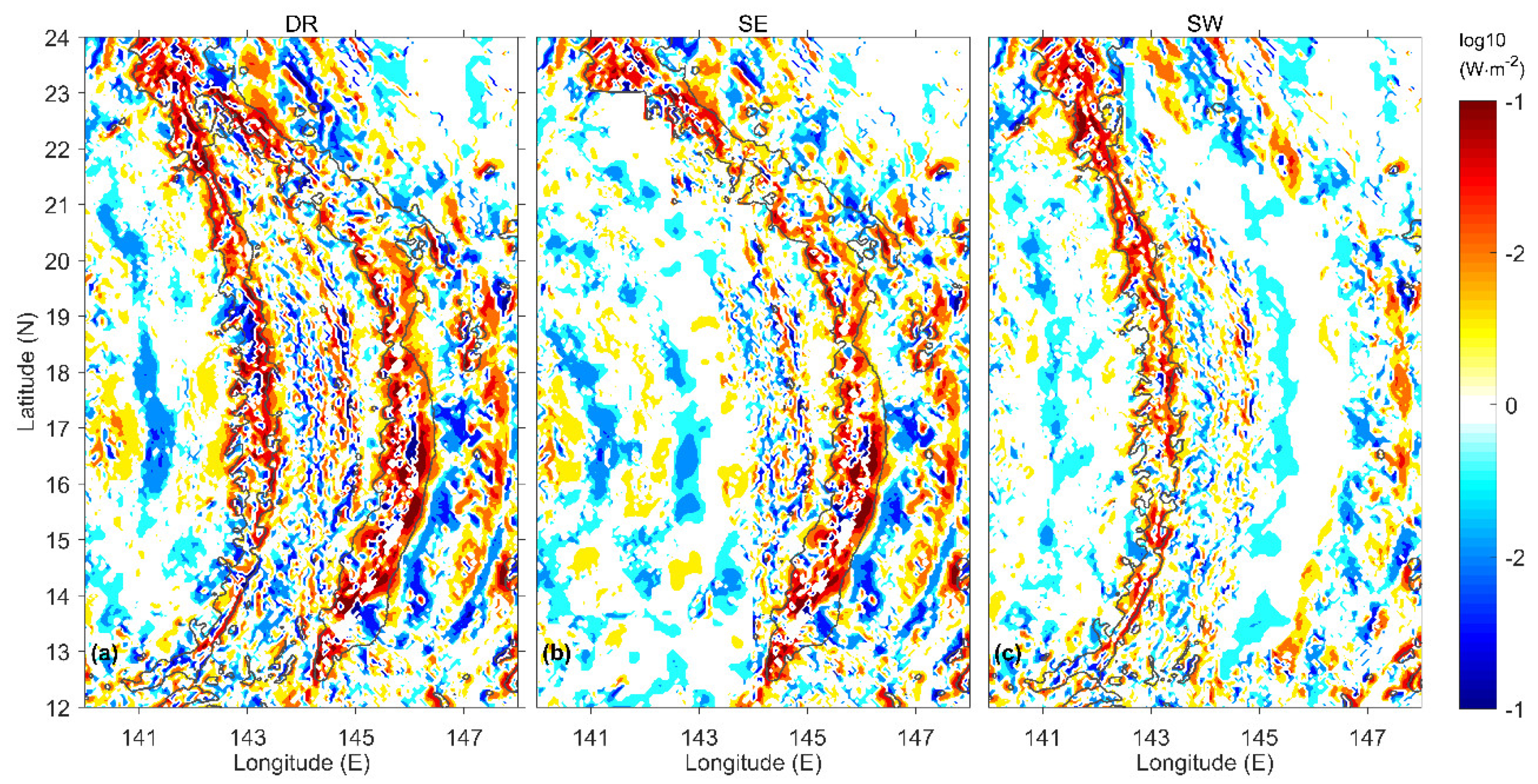
The barotropic-to-baroclinic conversion rate of tidal current determines the distribution of internal tide in global ocean with rough topography. Positive conversion indicates energy transfer from barotropic tide to baroclinic tide, and negative conversion indicates energy transfer from baroclinic tide back to barotropic tide, which only occurs when the phase difference between the density perturbation and the barotropic velocity is larger than 90°. At the Mariana double ridges, the spatial distributions of the depth-integrated barotropic-to-baroclinic conversion are highly inhomogeneous, with several orders of magnitude variation in spatial distribution (Figure 10a). The positive conversion mainly occurs at both sides of the two ridges with a magnitude of 100 W m−2, and the largest conversion is at the southern part of the eastern ridge [30]. Additionally, the large positive conversion appears at the supercritical and near-critical topography, indicating that the internal tide is mainly generated on these topographies at the Mariana Arc. The positive conversion rate is often accompanied by a nearby negative conversion rate, which suggests that some of the newly generated baroclinic tide will not propagate very far before being converted into barotropic tide again. Comparing the three cases, much larger conversion rates occur at the eastern ridge than the western ridge under three conditions, indicating the more important role of the eastern ridge on the generation of baroclinic tide than the western ridge at the Mariana Arc. Compared to the DR case, we can see that the conversions at the facing sides of the ridge under the SE and SW cases are much reduced (Figure 10b,c). This is also evidence that there is constructive internal tide interference between the two ridges, enhancing the conversion from barotropic to baroclinic.

3.6. Dissipation and Diapycnal Mixing

Figure 11 illustrates the distribution of bottom diapycnal diffusivity and bottom dissipation rate under the three cases at the Mariana Arc. Our results show that extremely enhanced mixing dominates this area under the DR case. High values of dissipation rate, reaching O (10−6 W kg−1), are accompanied by the diapycnal diffusivity reaching O (10−1 m2 s−1), which is several orders of magnitudes higher than the mixing of the open ocean. This level of high mixing condition has been found in many ocean ridges and hills [41,42,43]. The strongest dissipation rate occurs on the crests of the southern part of the eastern ridge, where the topography becomes steep and the slope criticality reaches its maximum value along the ridge [30]. Although the steepness of the topography leads to an increase in dissipation rate, the dissipated energy has little effect on the mixing at steep positions. Strong mixing occurs at a deeper position near the two ridges. This is due to weaker stratification in the deep water, which makes mixing easier. Moreover, we can see that the mixing between the two ridges is nearly one order of magnitude higher than the mixing outside the two ridges. That’s because the supercritical slope acts as a barrier at rough topography, where most incoming energy is reflected back. Because the two ridges are supercritical at most places, the energy reflected back by the two ridges enhance the mixing between them.
Comparing the three cases, we find that omitting one ridge has a significant effect on the diapycnal diffusivity. The dissipation rate also changed under those two single ridge cases but not as significant as the changing of diapycnal diffusivity. Omitting any one ridge, the dissipation rate is reduced significantly compared with that under the DR case, and removing the eastern ridge causes a bigger reduction of dissipation than removing the western ridge because the eastern ridge is the main source of the baroclinic tide. The diapycnal mixing is reduced as well under both cases, but without significant difference between the two cases at the inner region of the two ridges. When there is only one ridge left, the lack of internal tide interference from the other ridge and of the blocking effect of the supercritical topography on the internal tide results in a general reduction of the diapycnal mixing at this inner region. The only significant difference can be found at the latitude of 17° N, where the diapycnal mixing in the SE case is larger at the longitude of 140° E to 141° E compared with the SW case. We believe this is further evidence that the eastern ridge is the main source of internal tide.
This is because dissipation is mainly affected by supercritical topography, while mixing is modulated by the interference caused by the double ridge topography. Omitting one ridge does not affect the other ridge’s topography but removes the interference. On the whole, the incoming M2 internal tide is reflected between the supercritical double ridge topography and dissipated on the subcritical topography between the two ridges, enhancing the diapycnal mixing there.

4. Discussion

4.1. Enhancement of Conversion Dissipation and Divergence

Buijsman et al. [22] calculated the double ridge internal tide interference at the Luzon Strait and found that the double ridge topography can amplify the barotropic-to-baroclinic energy conversion, energy flux divergence, and dissipation in this area. They also proved that the amplification is not only determined by the height of the two ridges but is also determined by the distance between the two ridges by comparing their 3-D result with several 2-D knife-edge models. In this study, we also calculate the amplification of the barotropic-to-baroclinic energy conversion, energy flux divergence, and dissipation by the double ridges in the Mariana Arc by using their method. The amplification for conversion can be calculated as [22]:
Ψ C = C D R ( C W R + C E R ) C W R + C E R
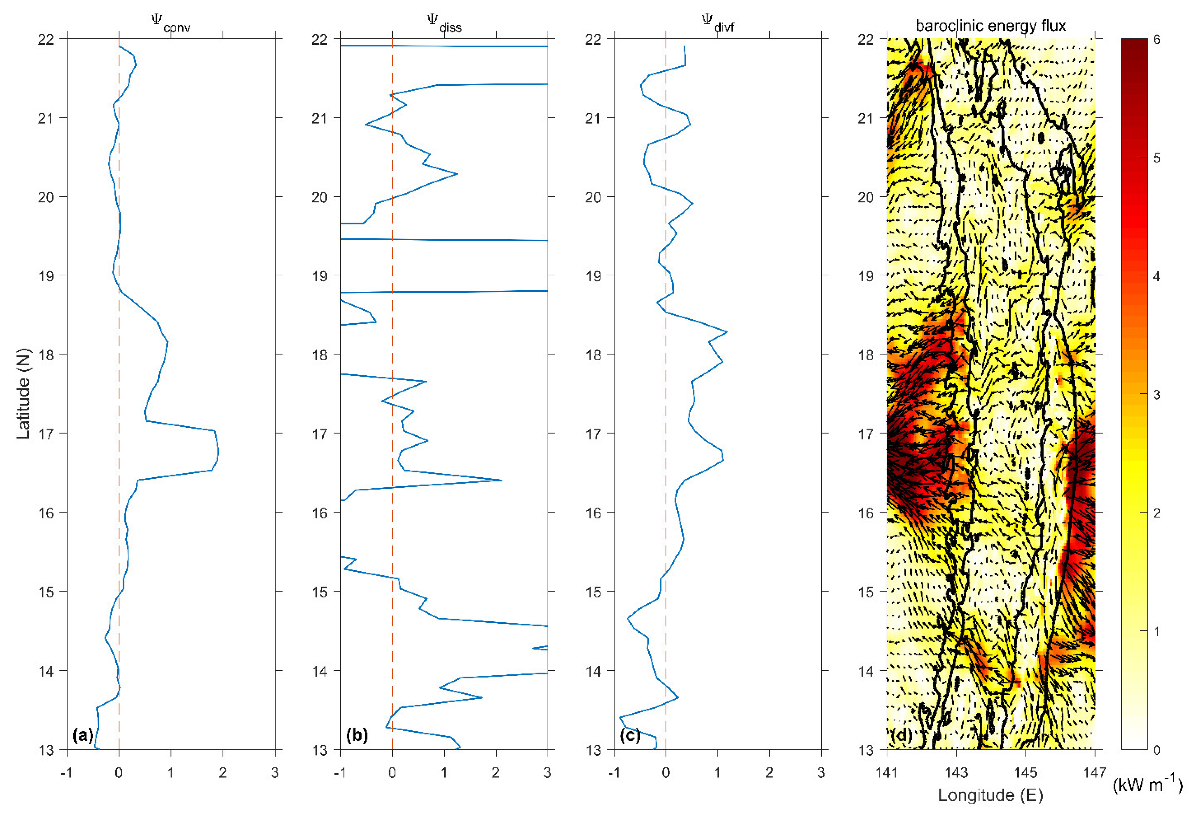
where the subscripts DR, WR, and ER refer to the DR, SW, and SR cases, respectively. Ψ > 0 mean that the conversion of the double ridge is larger than the sum of the two single ridge cases, indicating that constructive interference is done by the double ridge topography. Ψ < 0 means that destructive interference occurs. The amplification calculation method of other variables is the same. In order to calculate using Formula (20), the time-mean and depth-integrated variables are first zonally integrated and then meridionally averaged in three grids (0.125°) for the three cases. The amplification of conversion, dissipation, and divergence are presented in Figure 12a–c. The amplification of conversion is larger than zero at 15° N~18.7° N in the central part of the two ridges, indicating that the conversion rate is amplified due to the internal tide resonance between the two ridges. This is consistent with our previous analysis of the conversion rate in Section 3.5. The amplification of divergence is also larger than zero at about the same latitudes as the conversion rate. Moreover, the baroclinic flux energy is the largest at these latitudes according to Figure 12d, indicating that the internal tide resonance amplifies flux divergence at these latitudes. Another possibility is that the amplification of divergence is due to the amplification of conversion, because more baroclinic energy is conversed from the barotropic tide at these latitudes. The amplification of dissipation is larger than 0 at most latitudes, with several peaks at 14~15°, 19°, and 22°. We can see that these positions either have supercritical topography or high energy flux. The amplification of the dissipation is much larger than that of the conversion and flux divergence because the dissipation scales with u 3 , while conversion and divergence scales with u 2 [35]. However, we have not studied the influence of height, separate distance, and the arc of these two ridges on internal tides. Further study is needed to clarify the influence of these factors.

4.2. Energy Budget

Figure 13 illustrates the energy budget of the internal tide in the three cases, including the area-integrated barotropic-to-baroclinic conversion (conv), the divergence of baroclinic energy flux (divf), and the dissipation of baroclinic tide (diss). The arrows crossing the dashed lines represent the propagation direction of the integral of baroclinic energy on each boundary. In the DR cases, 0.24 GW, 2.33 GW, 2.41 GW, and 0.08 GW of the baroclinic energy propagates to the north, west, east, and south out of the boxed area, respectively (Figure 13a). In the area, 6.62 GW of barotropic energy transfers to internal tide, of which 5.29 GW of the internal tide energy propagates outward, accounting for 79% of the total internal tide energy. The remaining 21% of the total internal tide energy dissipates locally. Our results show slight difference with Kerry et al. [30] and Wang Yang et al. [24], which may be due to a different model setup and a different size of the integral area.
For the SE case (Figure 13b), 0.22 GW, 1.52 GW, 1.53 GW, and 0.07 GW of the baroclinic energy propagate outward from the north, west, east, and south boundary, respectively. In this case, 3.89 GW of the barotropic energy transfers to internal tide, of which 3.46 GW of the internal tide energy propagates outward, accounting for 88% of the total internal tide energy. The remaining 12% of the total internal tide energy is dissipated locally.
For the SW case (Figure 13c), 0.12 GW, 1.11 GW, 0.77 GW, and 0.01 GW of baroclinic energy propagates outward from the north, west, east, and south boundary, respectively. In this case, only 2.58 GW of the barotropic energy transfers to internal tide, of which 2.13 GW of the internal tide energy propagates outward, accounting for 82% of the total internal tide energy. The remaining 18% of the total internal tide energy is dissipated locally.
All of the three cases show that the internal tide propagates mainly along the east-west direction. Comparing the SE and SW cases, we can see that the conversion and divergence of the SE case are 34% and 38% larger than the SW case. These match our previous suggestion that the eastern ridge is the main source of internal tide generation at the Mariana double ridges. However, present study only covered M2 internal tide. Other internal tide such as S2, K1, and O1 may have different features under the double ridge case and two singe ridge cases. Therefore, further study based on different internal tide components is needed in order to clarify the internal tidal energetics in this area.

5. Summary

Using a non-hydrostatic MITgcm numerical model and parameterization methods, the generation and dissipation processes of M2 internal tide are investigated in the Mariana double ridges in this study. In addition, the internal tide-induced diapycnal mixing is evaluated at the same time in this area. Based on the results, the scientific contributions of our paper are concluded in this section: (1) Although the magnitudes of loss from barotropic tide going into internal tide at the Mariana double ridges are smaller than those at the Hawaiian and Luzon Ridges, their contribution to energy conversion in ocean cannot be ignored; (2) The greater importance of the eastern ridge compared to the western ridge regarding the generation, propagation, and dissipation of internal tides in the study area is identified, which help us to understand how such complex topography effects energy cascade in ocean; (3) The internal tide resonance between the Mariana double ridges is illustrated, and the latitude of the strongest resonance is found, which tells us how energy propagates in this kind of complex topography; (4) Three-dimensional diapycnal diffusivities are quantified at the Mariana double ridges, and their levels are comparable with those at other abrupt topographies, such as the Luzon, Mid-Atlantic, and Hawaiian Ridges, indicating its important role on modulating ocean features.

Author Contributions

Conceptualization, H.X., Q.C. and Q.Y.; methodology, Q.C., L.Y. and H.X.; validation, Q.C., L.Y., P.A.V., H.J. and Z.N.; formal analysis, Q.C. and H.X.; resources, H.X., Q.Y. and Q.X.; data curation, Q.C. and L.Y.; writing—original draft preparation, Q.C.; writing—review and editing, Q.C., P.A.V. and H.X.; visualization, Q.C. and L.Y.; supervision, H.X. and Q.Y.; project administration, H.X. and Q.Y.; funding acquisition, H.X., Q.Y. and Q.X. All authors have read and agreed to the published version of the manuscript.

Funding

This research is funded by the National Key R&D Program of China (grant 2018YFC0309800), the National Science Foundation of China (grants 41576006, 41576009, 41676015), the Strategic Priority Research Program of the CAS (grant XDA13030302) and the CAS Frontier Basic Research Project under (grant QYJC201910).

Institutional Review Board Statement

Not applicable.

Informed Consent Statement

Not applicable.

Data Availability Statement

The General Bathymetric Chart of the Oceans (GEBCO_08) bathymetry data is freely available online at http://www.gebco.net (accessed on 20 April 2020). World Ocean Database and World Ocean Atlas (WOA18) dataset are freely available online at http://wod.iode.org/SELECT/dbsearch/dbsearch.html/ (accessed on 20 April 2020) and https://www.nodc.noaa.gov/OC5/SELECT/woaselect/woaselect.html/ (accessed on 20 April 2020), respectively. Observed surface elevation data from the Center for Operational Oceanographic Products and Services, NOAA are freely available at https://www.noaa.gov/ (accessed on 20 April 2020). OTIS dataset is freely available at http://volkov.oce.orst.edu/tides/PO.html/ (accessed on 20 April 2020).

Conflicts of Interest

The authors declare no conflict of interest.

References

  1. Munk, W.H. Abyssal recipes. Deep. Sea Res. Oceanogr. Abstr. 1966, 13, 707–730. [Google Scholar] [CrossRef]
  2. Munk, W.; Wunsch, C. Abyssal recipes II: Energetics of tidal and wind mixing. Deep. Sea Res. I Oceanogr. Res. Pap. 1998, 45, 1977–2010. [Google Scholar] [CrossRef]
  3. Huang, R.X. Mixing and energetics of the oceanic thermohaline circulation. J. Phys. Oceanogr. 1999, 29, 727–746. [Google Scholar] [CrossRef]
  4. Wunsch, C.; Ferrari, R. Vertical mixing, energy, and the general circulation of the oceans. Annu. Rev. Fluid Mech. 2004, 36, 281–314. [Google Scholar] [CrossRef] [Green Version]
  5. Gregg, M.C. Diapycnal mixing in the thermocline: A review. J. Geophys. Res. Space Phys. 1987, 92, 5249–5286. [Google Scholar] [CrossRef]
  6. Toole, J.M.; Schmitt, R.W.; Polzin, K.L.; Kunze, E. Near-boundary mixing above the flanks of a midlatitude seamount. J. Geophys. Res. Space Phys. 1997, 102, 947–959. [Google Scholar] [CrossRef]
  7. Ledwell, J.R.; Watson, A.; Law, C.S. Mixing of a tracer in the pycnocline. J. Geophys. Res. Space Phys. 1998, 103, 21499–21529. [Google Scholar] [CrossRef]
  8. Egbert, G.D.; Ray, R.D. Significant dissipation of tidal energy in the deep ocean inferred from satellite altimeter data. Nat. Cell Biol. 2000, 405, 775–778. [Google Scholar] [CrossRef] [PubMed]
  9. Laurent, L.C.S.; Simmons, H.L.; Jayne, S. Estimating tidally driven mixing in the deep ocean. Geophys. Res. Lett. 2002, 29. [Google Scholar] [CrossRef]
  10. Ledwell, J.R.; Montgomery, E.; Polzin, K.L.; Laurent, L.C.S.; Schmitt, R.W.; Toole, J.M. Evidence for enhanced mixing over rough topography in the abyssal ocean. Nat. Cell Biol. 2000, 403, 179–182. [Google Scholar] [CrossRef] [PubMed]
  11. Wang, X.; Peng, S.; Liu, Z.; Huang, R.X.; Qian, Y.-K.; Li, Y. Tidal mixing in the South China Sea: An estimate based on the internal tide energetics. J. Phys. Oceanogr. 2016, 46, 107–124. [Google Scholar] [CrossRef]
  12. Cox, C.; Sandstrom, H. Coupling of internal and surface waves in water of variable depth. Deep. Sea Res. Oceanogr. Abstr. 1964, 11, 659–660. [Google Scholar] [CrossRef]
  13. Bell, T.H. Lee waves in stratified flows with simple harmonic time dependence. J. Fluid Mech. 1975, 67, 705–722. [Google Scholar] [CrossRef]
  14. Bell, T.H. Topographically generated internal waves in the open ocean. J. Geophys. Res. Space Phys. 1975, 80, 320–327. [Google Scholar] [CrossRef]
  15. Hibiya, T. Generation mechanism of internal waves by tidal flow over a sill. J. Geophys. Res. Space Phys. 1986, 91, 7697. [Google Scholar] [CrossRef]
  16. Llewellyn Smith, S.G.; Young, W.R. Conversion of the barotropic tide. J. Phys. Oceanogr. 2002, 32, 1554–1566. [Google Scholar] [CrossRef]
  17. Balmforth, N.J.; Ierley, G.R.; Young, W.R. Tidal conversion by subcritical topography. J. Phys. Oceanogr. 2002, 32, 2900–2914. [Google Scholar] [CrossRef]
  18. Radko, T.; Marshall, J. Eddy-induced diapycnal fluxes and their role in the maintenance of the thermocline. J. Phys. Oceanogr. 2004, 34, 372–383. [Google Scholar] [CrossRef]
  19. Holloway, P.E.; Merrifield, M.A. Internal tide generation by seamounts, ridges, and islands. J. Geophys. Res. Space Phys. 1999, 104, 25937–25951. [Google Scholar] [CrossRef]
  20. Merrifield, M.A.; Holloway, P.E.; Johnston, T.M.S. The generation of internal tides at the Hawaiian Ridge. Geophys. Res. Lett. 2001, 28, 559–562. [Google Scholar] [CrossRef]
  21. Zilberman, N.V.; Becker, J.M.; Merrifield, M.A.; Carter, G.S. Model estimates of M2 internal tide generation over Mid-Atlantic ridge topography. J. Phys. Oceanogr. 2009, 39, 2635–2651. [Google Scholar] [CrossRef]
  22. Buijsman, M.C.; Klymak, J.M.; Legg, S.; Alford, M.H.; Farmer, D.; MacKinnon, J.A.; Nash, J.D.; Park, J.-H.; Pickering, A.; Simmons, H. Three-dimensional double-ridge internal tide resonance in Luzon Strait. J. Phys. Oceanogr. 2014, 44, 850–869. [Google Scholar] [CrossRef] [Green Version]
  23. Niwa, Y. Three-dimensional numerical simulation of M2internal tides in the East China Sea. J. Geophys. Res. Space Phys. 2004, 109. [Google Scholar] [CrossRef]
  24. Wang, Y.; Xu, Z.; Yin, B.; Hou, Y.; Chang, H. Long-range radiation and interference pattern of multisource M 2 internal tides in the Philippine Sea. J. Geophys. Res. Oceans 2018, 123, 5091–5112. [Google Scholar] [CrossRef] [Green Version]
  25. Legg, S.; Adcroft, A. Internal wave breaking at concave and convex continental slopes. J. Phys. Oceanogr. 2003, 33, 2224–2246. [Google Scholar] [CrossRef]
  26. Nikurashin, M.; Legg, S. A Mechanism for local dissipation of internal tides generated at rough topography. J. Phys. Oceanogr. 2011, 41, 378–395. [Google Scholar] [CrossRef]
  27. Han, B.; Eden, C. The energetics of internal tides at the Luzon Ridge. Ocean. Dyn. 2019, 69, 1009–1022. [Google Scholar] [CrossRef]
  28. Mazloff, M.R.; Cornuelle, B.; Gille, S.T.; Wang, J. The importance of remote forcing for regional modeling of internal waves. J. Geophys. Res. Oceans 2020, 125. [Google Scholar] [CrossRef]
  29. Zhao, Z.; D’Asaro, E. A perfect focus of the internal tide from the Mariana Arc. Geophys. Res. Lett. 2011, 38. [Google Scholar] [CrossRef]
  30. Kerry, C.G.; Powell, B.S.; Carter, G.S. Effects of remote generation sites on model estimates of M2 internal tides in the Philippine Sea. J. Phys. Oceanogr. 2013, 43, 187–204. [Google Scholar] [CrossRef]
  31. Marshall, J.; Adcroft, A.; Hill, C.; Perelman, L.; Heisey, C. A finite-volume, incompressible Navier Stokes model for studies of the ocean on parallel computers. J. Geophys. Res. Space Phys. 1997, 102, 5753–5766. [Google Scholar] [CrossRef] [Green Version]
  32. Buijsman, M.C.; Legg, S.; Klymak, J. Double-ridge internal tide interference and its effect on dissipation in Luzon Strait. J. Phys. Oceanogr. 2012, 42, 1337–1356. [Google Scholar] [CrossRef]
  33. Niwa, Y.; Hibiya, T. Numerical study of the spatial distribution of the M2 internal tide in the Pacific Ocean. J. Geophys. Res. Space Phys. 2001, 106, 22441–22449. [Google Scholar] [CrossRef] [Green Version]
  34. Tian, J.; Lei, Z.; Zhang, X.; Liang, X.; Wei, Z. Estimates of M2 internal tide energy fluxes along the margin of Northwestern Pacific using TOPEX/POSEIDON altimeter data. Geophys. Res. Lett. 2003, 30, OCE 4-1. [Google Scholar] [CrossRef]
  35. Klymak, J.M.; Legg, S.M. A simple mixing scheme for models that resolve breaking internal waves. Ocean Model. 2010, 33, 224–234. [Google Scholar] [CrossRef]
  36. Cummins, P.F.; Oey, L.-Y. Simulation of Barotropic and Baroclinic Tides off Northern British Columbia. J. Phys. Oceanogr. 1997, 27, 762–781. [Google Scholar] [CrossRef]
  37. Mellor, G.L. Users Guide for a Three-Dimensional, Primitive equation, Numerical Ocean Model; Program in Atmospheric and Oceanic Sciences, Princeton University: Princeton, NJ, USA, 2004. [Google Scholar]
  38. Nash, J.D.; Alford, M.H.; Kunze, E. Estimating internal wave energy fluxes in the ocean. J. Atmos. Ocean. Technol. 2005, 22, 1551–1570. [Google Scholar] [CrossRef] [Green Version]
  39. Osborn, T.R. Estimates of the local rate of vertical diffusion from dissipation measurements. J. Phys. Oceanogr. 1980, 10, 83–89. [Google Scholar] [CrossRef] [Green Version]
  40. Duda, T.F.; Rainville, L. Diurnal and semidiurnal internal tide energy flux at a continental slope in the South China Sea. J. Geophys. Res. Space Phys. 2008, 113. [Google Scholar] [CrossRef] [Green Version]
  41. Klymak, J.M.; Moum, J.N.; Nash, J.D.; Kunze, E.; Girton, J.B.; Carter, G.S.; Lee, C.M.; Sanford, T.B.; Gregg, M.C. An estimate of tidal energy lost to turbulence at the Hawaiian ridge. J. Phys. Oceanogr. 2006, 36, 1148–1164. [Google Scholar] [CrossRef]
  42. Lee, C.M.; Sanford, T.B.; Kunze, E.; Nash, J.D.; Merrifield, M.A.; Holloway, P.E. Internal tides and turbulence along the 3000-m isobath of the Hawaiian Ridge. J. Phys. Oceanogr. 2006, 36, 1165–1183. [Google Scholar] [CrossRef]
  43. Laurent, L.C.S.; Thurnherr, A. Intense mixing of lower thermocline water on the crest of the Mid-Atlantic Ridge. Nat. Cell Biol. 2007, 448, 680–683. [Google Scholar] [CrossRef] [PubMed]
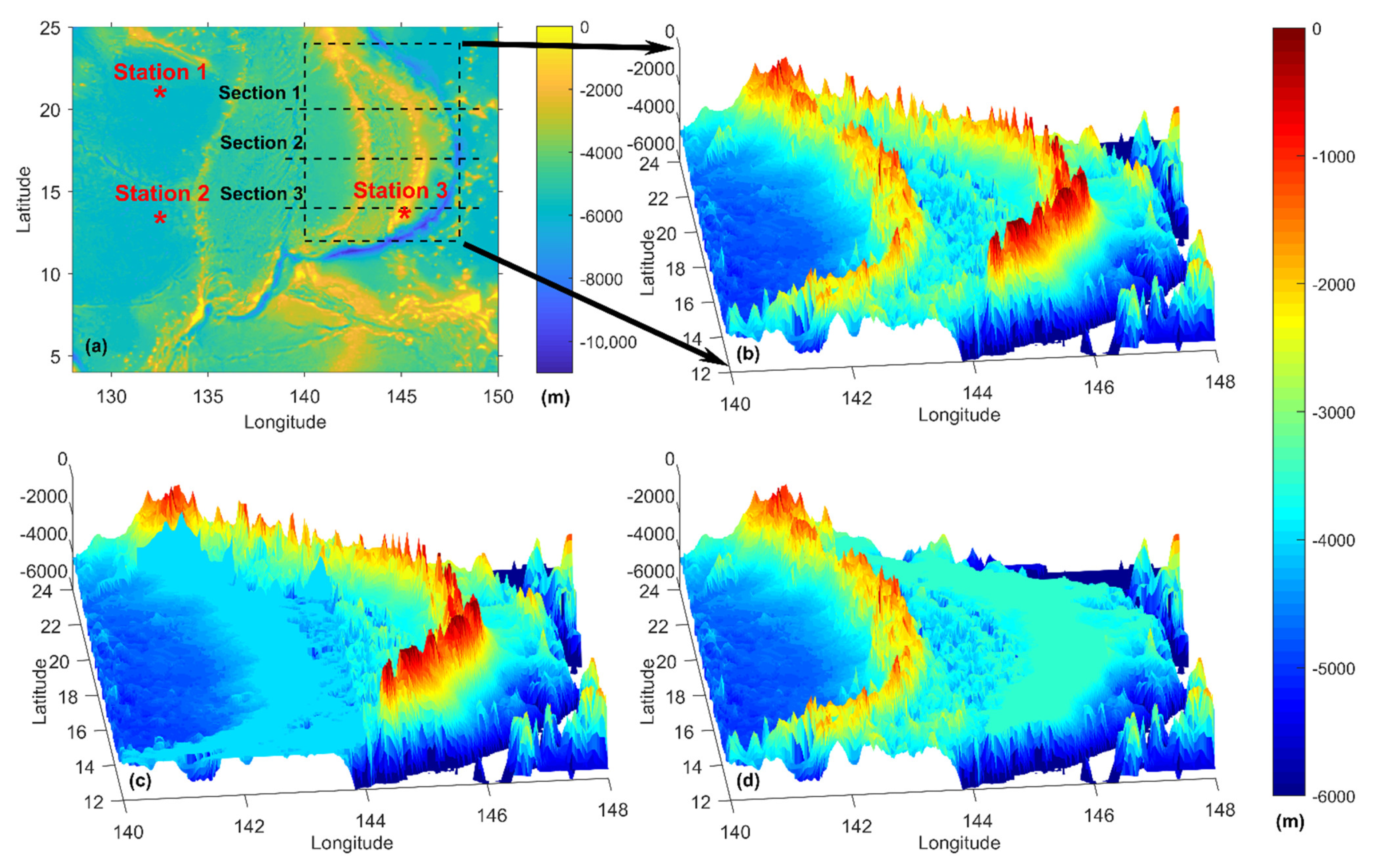
Figure 1. Model domain and bathymetry in the northwest Pacific (a). The black dashed box is the target area in this study. Zonal Section 1, Section 2, and Section 3 are selected at the latitude of 20° N, 17° N, and 14° N, respectively. Red stars represent the mooring observation stations. Detailed topography at the target area under DR (b), SE (c), and SW (d) cases.
Jmse 09 00592 g001
Figure 2. Model simulated (a) and OTIS (b) M2 barotropic tide amplitude (m) and Model simulated (c) and OTIS (d) M2 barotropic tide phase (degree). Gray contours represent the 2000-m isobaths.
Jmse 09 00592 g002
Figure 3. Slope criticality of the Mariana double ridges (a). Barotropic tidal energy flux (vector) and its magnitude (color shading) (kW m–1) (b). The background contours represent the 3000-m isobaths.
Jmse 09 00592 g003
Figure 4. Vertical distributions of M2 baroclinic tidal ellipse (m/s) along three zonal sections under (ac) for DR case, (df) for SE case, and (gi) for SW case. Gray shaded areas represent topography along the sections.
Jmse 09 00592 g004
Figure 5. Depth-integrated baroclinic energy flux (vector) and its magnitude (color shading) (kW m–1) under (a) for DR case, (b) for SE case, and (c) for SW case. The background contours represent the 3000-m isobaths.
Jmse 09 00592 g005
Figure 6. The amplitude of M2 internal tidal zonal velocity (m/s) along 20° N (a), 17° N (b), and 14° N (c). Scheme 20° N (d), 17° N (e), and 14° N (f) sections. The result of subtracting the amplitude (m/s) of the DR case from the SW case (SW-DR) along 20° N (g), 17° N (h), and 14° N (i) sections. Gray shaded areas represent topography along the sections.
Jmse 09 00592 g006
Figure 7. The phase (degree) of the internal tidal zonal velocity along the 20° N (a), 17° N (b), and 14° N (c) sections under the DR case. The phase difference (degree) between the DR and SE cases (DR-SE) along 20° N (d), 17° N (e), and 14° N (f). The phase difference (degree) between the DR and SW cases (DR-SW) along 20° N (g), 17° N (h), and 14° N (i). The phase difference (degree) between the SE and SW cases (SE-SW) along 20° N (j), 17° N (k), and 14° N (l). Gray shaded areas represent topography along the sections.
Jmse 09 00592 g007
Figure 8. Sampled 5 stations (named WW, WE, M, EW, and EE) along 20° N (a), 17° N (b), and 14° N (c) sections (dashed vertical lines). The longitudes of the 15 stations are 142.6° E, 143.1° E, 144.1° E, 145.1° E, 145.6° E at 20° N; 142.8° E, 143.35° E, 144.1° E, 145.6° E, 145.94° E at 17° N; and 142.6° E, 142.85° E, 144.1° E, 144.72° E, 145.3° E at 14° N. The bold line represents the slope criticality. The horizontal dashed line represents the criticality index α = 1. Gray shaded areas represent topography along the sections.
Jmse 09 00592 g008
Figure 9. Temporal variations of M2 internal tide zonal velocity (m/s) at selected stations under DR (upper box), SE (middle box), and SW (lower box) cases from surface to bottom.
Jmse 09 00592 g009
Figure 10. Depth-integrated barotropic-to-baroclinic conversion rates (W m−2) under the DR (a), SE (b), and SW (c) cases. The background black contours represent the 3000-m isobaths.
Jmse 09 00592 g010
Figure 11. Bottom diapycnal diffusivity (m2 s–1) under the DR (a), SE (b), and SW (c) cases (upper panel). Bottom dissipation rate (W kg–1) under the DR (d), SE (e), and SW (f) cases (lower panel). The background contours represent the 3000-m isobaths.
Jmse 09 00592 g011
Figure 12. The zonally integrated amplification of the conversion (a), dissipation (b), and divergence (c) at the Mariana double ridges. Depth-integrated baroclinic energy flux (vector) and its magnitude (color shading) (kW m–1) at the double ridges (d). The background contours represent the 3000-m isobaths.
Jmse 09 00592 g012
Figure 13. Diagrams of the M2 internal tides energy budget at the Mariana Arc under the DR (a), SE (b), and SW (c) cases. The black dashed box bounds the integration area for our calculations. Conv, Divf, and Diss label the area-integrated conversion rate from barotropic to baroclinic tidal energy, divergence of baroclinic energy flux, and dissipation rate of the baroclinic energy (GW), respectively. The arrow crossing each dashed line represents the propagation direction of the integrated baroclinic energy on each boundary. The background contours represent the 3000-m isobaths.
Jmse 09 00592 g013
Table 1. Model simulated and observed M2 barotropic tide amplitudes (m) and phases (degree) at three stations. The absolute RMS (m) and its percentage (%) are calculated.
Station Amplitude (m)PhaseRMS (m)Percentage (%)
Station 1MITgcm0.48281.990.0234.7
OBS0.49285.71
Station 2MITgcm0.52282.620.05910.7
OBS0.55290.98
Station 3MITgcm0.16265.640.03733.6
OBS0.11271.50
Publisher’s Note: MDPI stays neutral with regard to jurisdictional claims in published maps and institutional affiliations.