Article

Small–Scale Experimental Investigation of Fatigue Performance Improvement of Ship Hatch Corner with Shot Peening Treatments by Considering Residual Stress Relaxation

1
Key Laboratory of High Performance Ship Technology (Wuhan University of Technology), Ministry of Education, Wuhan 430063, China
2
Department of Naval Architecture, Ocean and Structural Engineering, School of Transportation, Wuhan University of Technology, Wuhan 430063, China
3
Green & Smart River–Sea–Going Ship, Cruise and Yacht Research Center, Wuhan University of Technology, Wuhan 430063, China
4
Department of Automotive Engineering, School of Automotive Engineering, Wuhan University of Technology, Wuhan 430070, China
*
Author to whom correspondence should be addressed.
J. Mar. Sci. Eng. 2021, 9(4), 419; https://doi.org/10.3390/jmse9040419
Submission received: 15 March 2021 / Revised: 7 April 2021 / Accepted: 7 April 2021 / Published: 13 April 2021
(This article belongs to the Special Issue Ship Structures)

Abstract

:
Ship hatch corner is a common structure in a ship and its fatigue problem has always been one of the focuses in ship engineering due to the long–term high–stress concentration state during the ship’s life. For investigating the fatigue life improvement of the ship hatch corner under different shot peening (SP) treatments, a series of fatigue tests, residual stress and surface topography measurements were conducted for SP specimens. Furthermore, the distributions of the surface residual stress are measured with varying numbers of cyclic loads, investigating the residual stress relaxation during cyclic loading. The results show that no matter which SP process parameters are used, the fatigue lives of the shot–peened ship hatch corner specimens are longer than those at unpeened specimens. The relaxation rate of the residual stress mainly depends on the maximum compressive residual stress (σRSmax) and the depth of the maximum compressive residual stress (δmax). The larger the values of σRSmax and δmax, the slower the relaxation rates of the residual stress field. The results imply that the effect of residual stress field and surface roughness should be considered comprehensively to improve the fatigue life of the ship hatch corner with SP treatment. The increase in peening intensity (PI) within a certain range can increase the depth of the compressive residual stress field (CRSF), so the fatigue performance of the ship hatch corner is improved. Once the PI exceeds a certain value, the surface damage caused by the increase in surface roughness will not be offset by the CRSF and the fatigue life cannot be improved optimally. This research provides an approach of fatigue performance enhancement for ship hatch corners in engineering application.

1. Introduction

As a large–scale structure integrating safety, economy and practicability, the ship’s fatigue problem is the focus of attention. The International Association of Classification Society (IACS) Regulations for Bulk Carriers [1] and China Classification Society (CCS)’s “Guidelines for Fatigue Strength Assessment of Hull Structures” [2] both provide relevant regulations for ship hull structures that are prone to fatigue problems. During the service life, the hull structure is affected by alternating stress loads such as wave–induced load, which have a great impact on its fatigue properties. Figure 1 shows a fatigue crack in the hatch corner of a certain ship. Guoqing et al. [3] proposed to use the equivalent wave method to evaluate the fatigue life of hatch corners. The results of the equivalent wave method agree well with those from the spectral fatigue analysis. Selle et al. [4] used the finite element method with a fatigue assessment technique developed by Germanischer Lloyd (GL) to analyze the effect of radii of ship hatch corners on fatigue performance. Yong et al. [5] conducted stress analysis on ship hatch corner structures based on the S–N curve method and studied the effects of different structure details on fatigue performance of ship hatch corners. Xu et al. [6,7] did a detailed study on the method of establishing a finite element analysis (FEA) model by laser measurement, proposed some optimized model generation methods, and used the CUF (Carrera unified formula) method developed by Carrera. [8] for numerical analysis. Jiancheng et al. [9] conducted research on stress concentration at ship hatch corners with large openings, and analyzed the effect of stress releasing hole and strengthened plates for reducing the stress concentration. However, researches on improving the fatigue performance of ship hatch corners has mainly been conducted to optimize the structure to reduce the stress concentration, and there are few analyses on improving fatigue performance of ship hatch corner directly through a certain treatment.
Compressive residual stresses on the surface layer help to inhibit crack initiation and expansion, which helps to improve the fatigue life and reliability of structures. For introducing compressive residual stress in the surface layer to prolong the fatigue life of the structure, some methods of surface treatment have been applied such as shot peening (SP), laser shock peening [10,11,12,13], high–frequency mechanical impact treatment [14,15,16], and ultrasonic impact treatment [17,18,19,20]. Among these kinds of treatments, SP is the most used treatment for its flexibility, low cost, and dispensing with pretreatment. SP is an effective cold working surface treatment in improving fatigue properties of structures [21,22] and is widely used in the aerospace industry, automobile industry, and other fields. However, there are few applications of SP in the shipbuilding industry. It can introduce compressive residual stresses to the surface layer and enhance the surface hardness and roughness by impacting on the surface with a mass of metallic or ceramic particles into the surface region. The compressive residual stress layers in the surface and subsurface of the shot–peened workpiece can partially offset the tensile stress generated by the alternating external load. Therefore, the compressive residual stress is recognized as the main strengthening factor to improve the fatigue performance of the specimen surface [23,24]. Gan et al. [25] studied the effect of SP on the fatigue life of T–welded joints via fatigue tests and residual stress measurements, proving that SP has significant benefits on specimens’ fatigue performance. Wohlfahrt [26] studied the influence of residual stress change by different peening conditions. For shot peening, it is indispensable to evaluate the residual stress field. However, these studies only consider the effect of the initial residual stress field and ignore the relaxation of the residual stress field during the cyclic loading process.
Generally, SP treatment can cause an increase in the surface roughness of the peened structure while excessive surface roughness has a negative impact on fatigue performance. Surface roughness is one of the important parameters for evaluating the surface integrity of materials, which has a significant effect on fatigue performance. The larger the roughness, the easier it is to cause local stress concentration and induce fatigue crack initiation [27]. Novovic et al. [28] studied the correlation between the surface roughness (Ra) and fatigue life, showing that when Ra is less than 0.1 μm, its effect is insignificant. If Ra is between 2 μm and 5 μm, it will have a positive effect on the fatigue life. Ruihong et al. [29] investigated the effect of SP on the surface roughness and fatigue properties of 300M steel by tests, proving that the effect of SP is not proportional to the peening intensity (PI).
There are also some investigations related to the relaxation of the residual stress field of the shot peening treatment. Residual stress relaxation in fatigue loading is one of the main factors that affect the improvement of fatigue strength by shot peening, as well as the surface conditions created by shot peening and the possibility of the relaxation of compressive residual stress field (CRSF) to push the crack source beneath the surface [30]. In terms of the effect of the stability of the residual stress field on the fatigue life, the shot–peened specimens will exhibit longer life times than the unpeened ones as long as the CRSFs of the shot–peened specimens remain stable [31]. Dalaei et.al. [32,33] considered the main relaxation of the residual stresses that take place during the first sub–block which is due to the large relaxation during the first loading cycle as well as the maximum strain amplitude present in the first sub–block. The effect of shot peening conditions on the stability of the residual stress field is also significant, Huang et al. [34] investigated fatigue performance improvement of different modified SP treatments, considered that CRSF stability has a great influence on fatigue strength of shot–peened specimens and suitable peening temperature can lead CRSF to be more stable. However, the actual structure in practical engineering has not been paid enough attention until now. All of the objects in related research are simple standard specimens and the locations of interest are not well described which makes the results not suitable for complex structures and makes it difficult to reflect the evolution law of the residual stress field on the actual structure in practical applications. In the study of the numerical method of the relaxation of CRSF, Ruiz et al. [35] analyzed the relaxation of high frequency mechanical impact treatment induced CRSF of a single–sided out–of–plane gusset welded joint by numerical analysis. This analysis method is also applicable to SP–induced CRSF.
As for engineering applications, even though applying suitable SP for a specific structure and mastering the law of relaxation of its residual stress field will improve the fatigue strength and life of the structure, which cannot be solved by structure design or optimization effectively, there are still few applications of SP treatment in improving fatigue performance of structures in ships, especially for a structure like the ship hatch corner ,where fatigue damage often occurs. For this specific structure, it is not enough to consider the introduced initial residual compressive stress field alone because the residual stress field will relax during cyclic fatigue loading, which leads to the decline of the SP–induced fatigue strengthening effect. If the SP treatment is to be used in the fatigue performance improvement of ship structures, the law of residual stress relaxation and how it is affected by the load and SP parameters should be investigated in detail. The research on SP and residual stress relaxation in ship hatch corners is worthy of being focused on since it can provide an approach to improving the fatigue life of the structures in ships that suffer from serious fatigue problems. Beyond that, a procedure of fatigue life assessment after SP enhancement can provide some reference for researchers and designers who focus on ship fatigue problems.
In order to provide a practical assessment of actual ship hatch corner structures in engineering application, the effects of CRSF and surface topographies on the fatigue performances of ship hatch corners were analyzed by experimental and numerical methods. Experimental research based on fatigue tests, surface topography measurements, and residual stress measurements were conducted to investigate the effect of SP on the fatigue life of ship hatch corner structures. Variations of residual stress fields at a specific area on the structure was derived by measurement during cyclic loading. The variation law of the residual stress field in ship hatch corners was analyzed. The effect of shot peening treatment on the surface topography of the structure and the relationship between the residual stress relaxation and fatigue life were investigated.

2. Experimental Setup

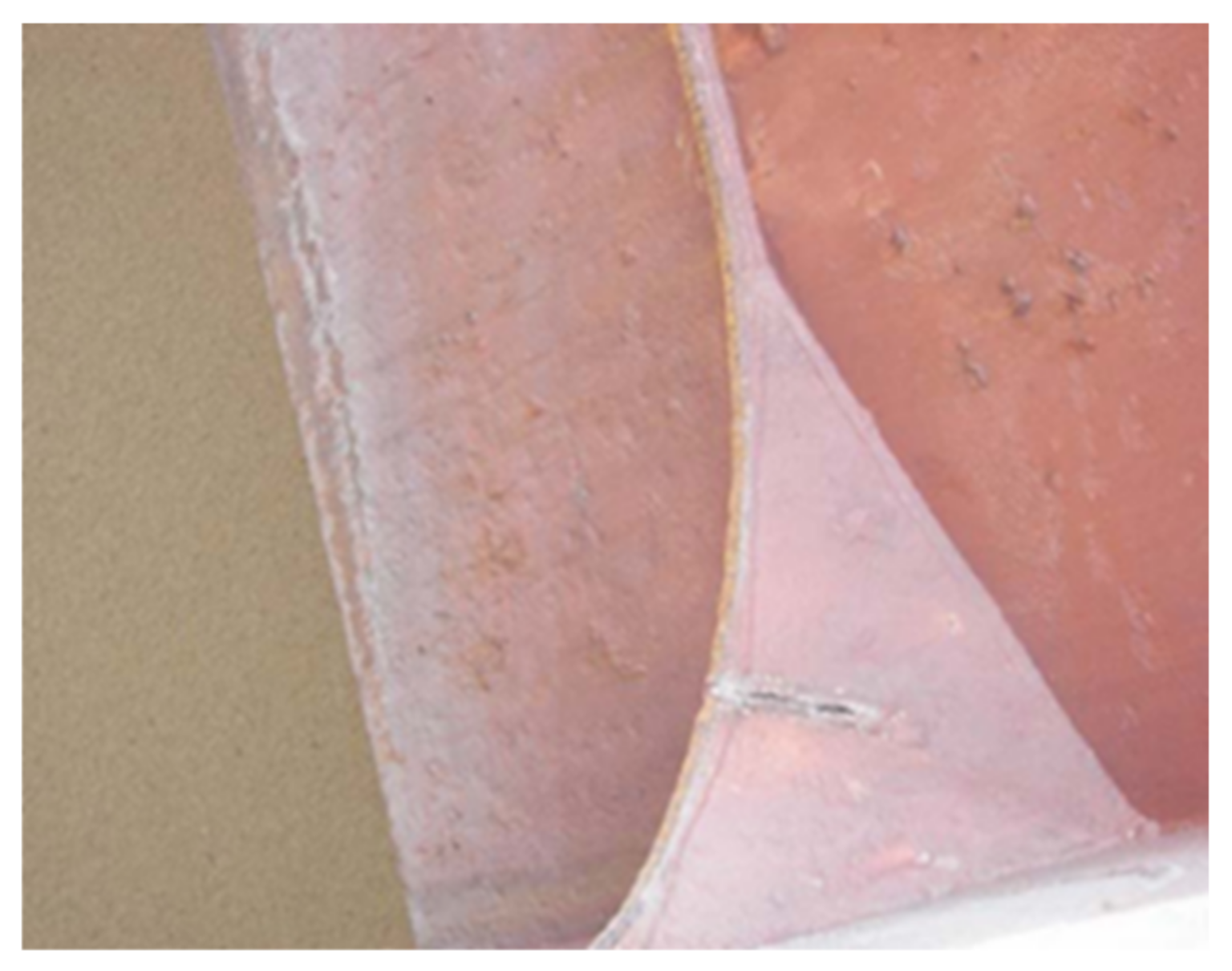
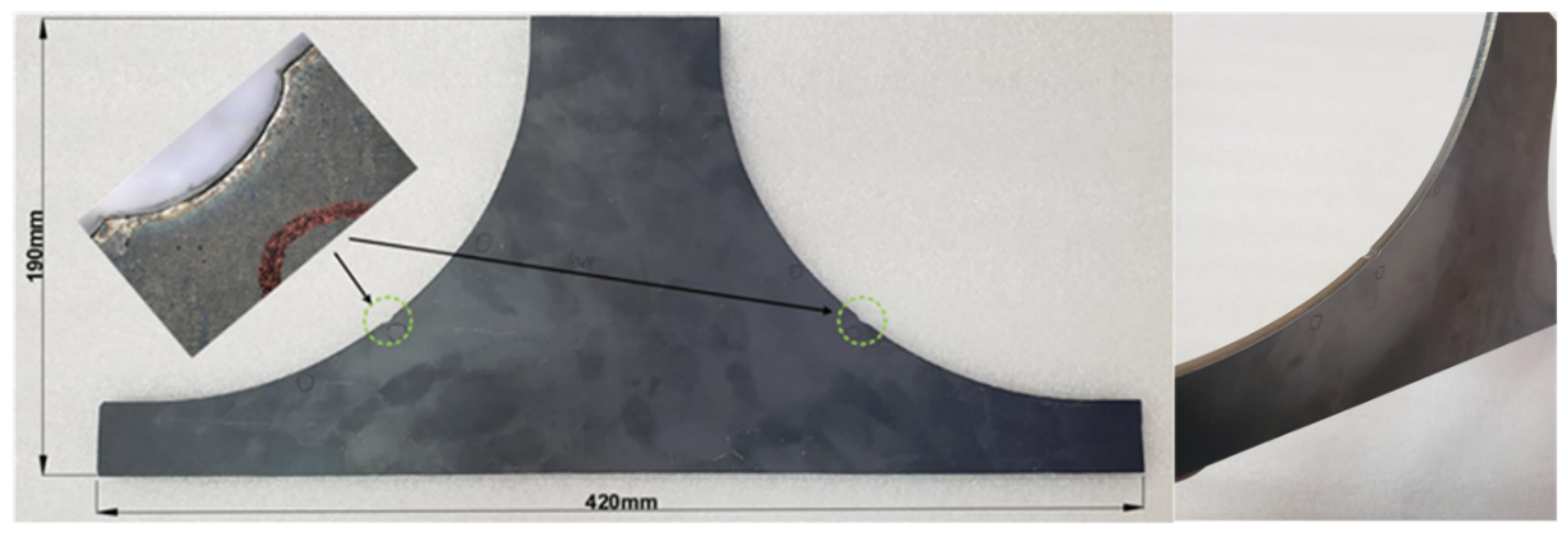
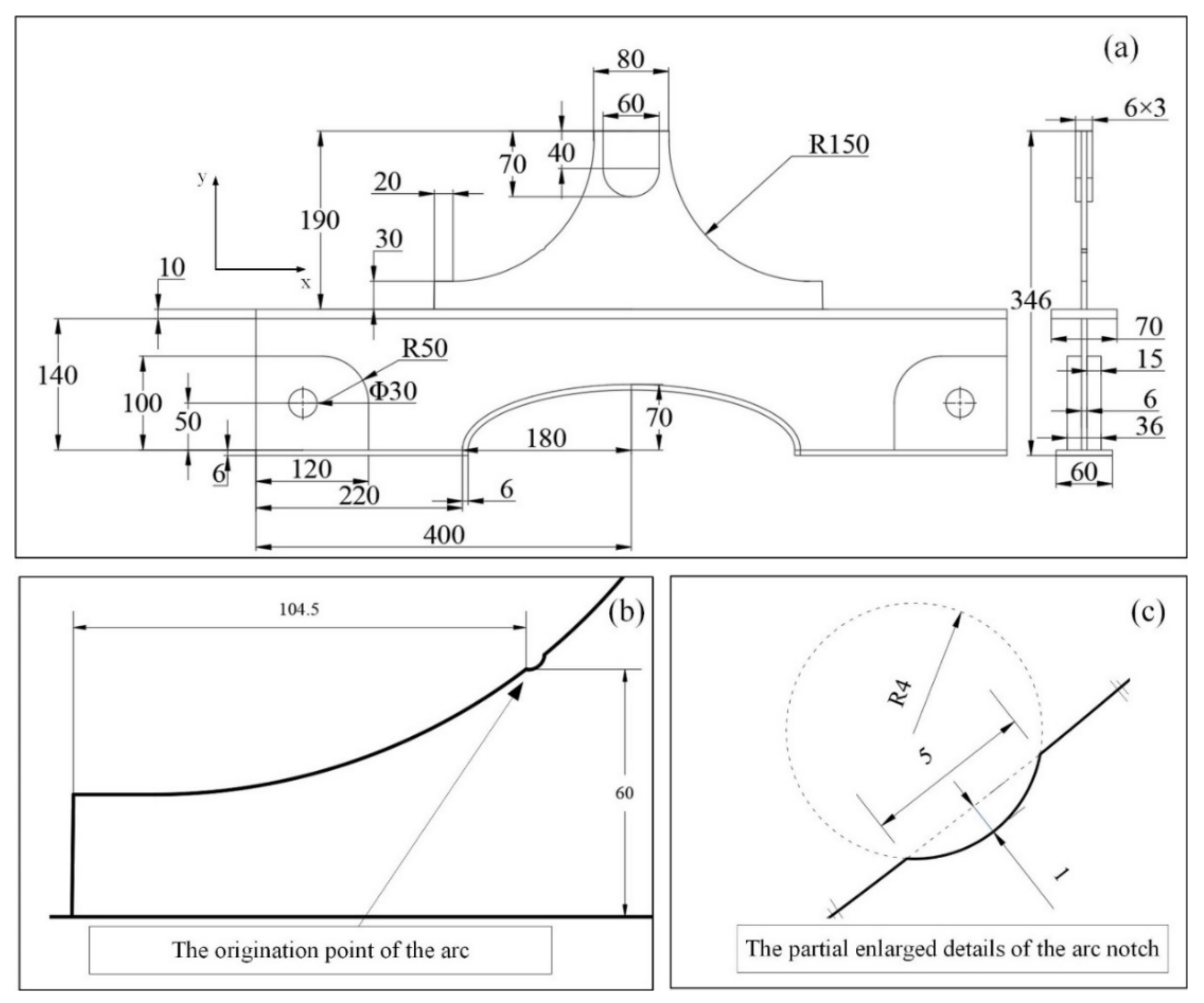
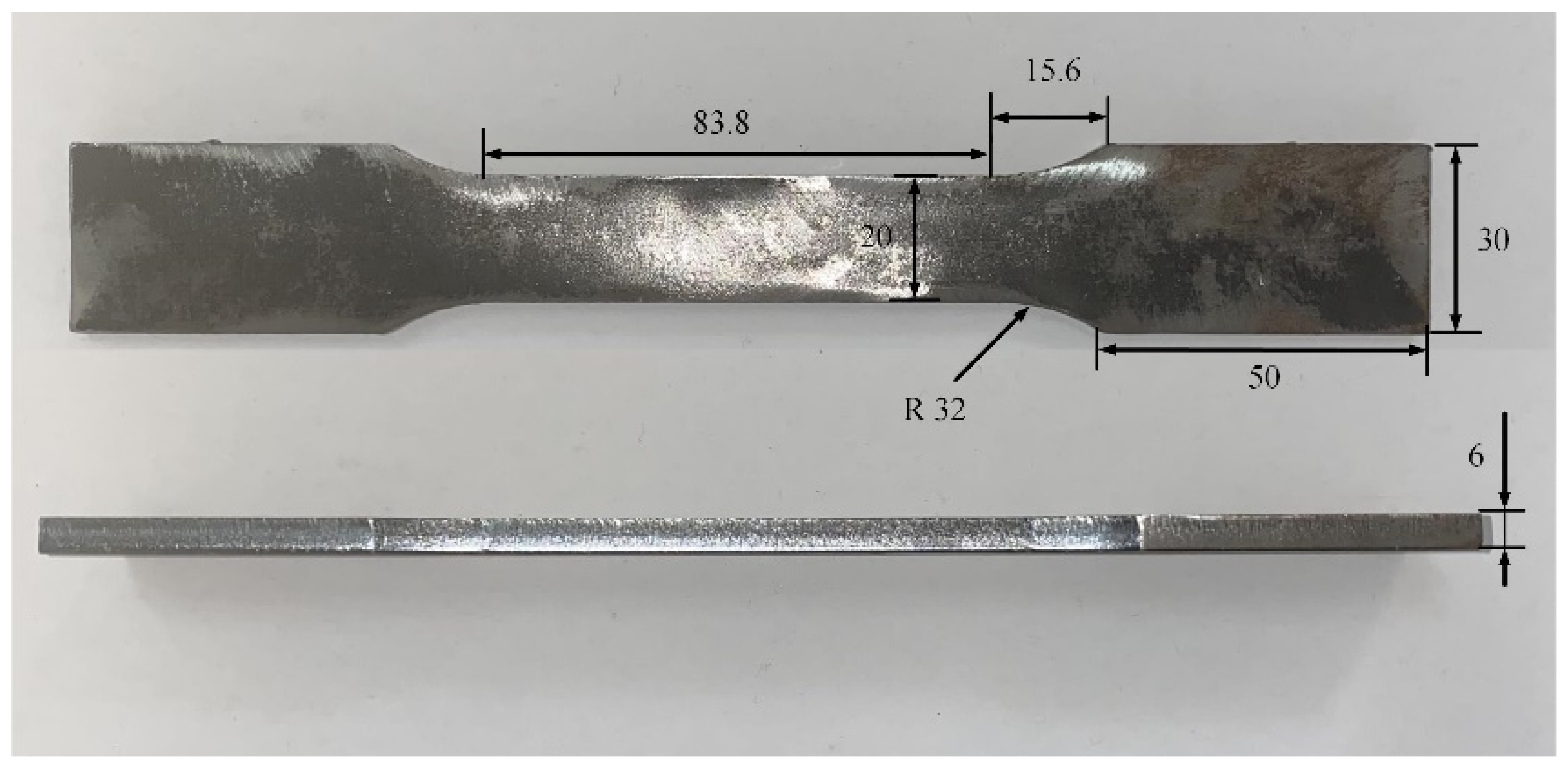
2.1. Specimen Design and Processing
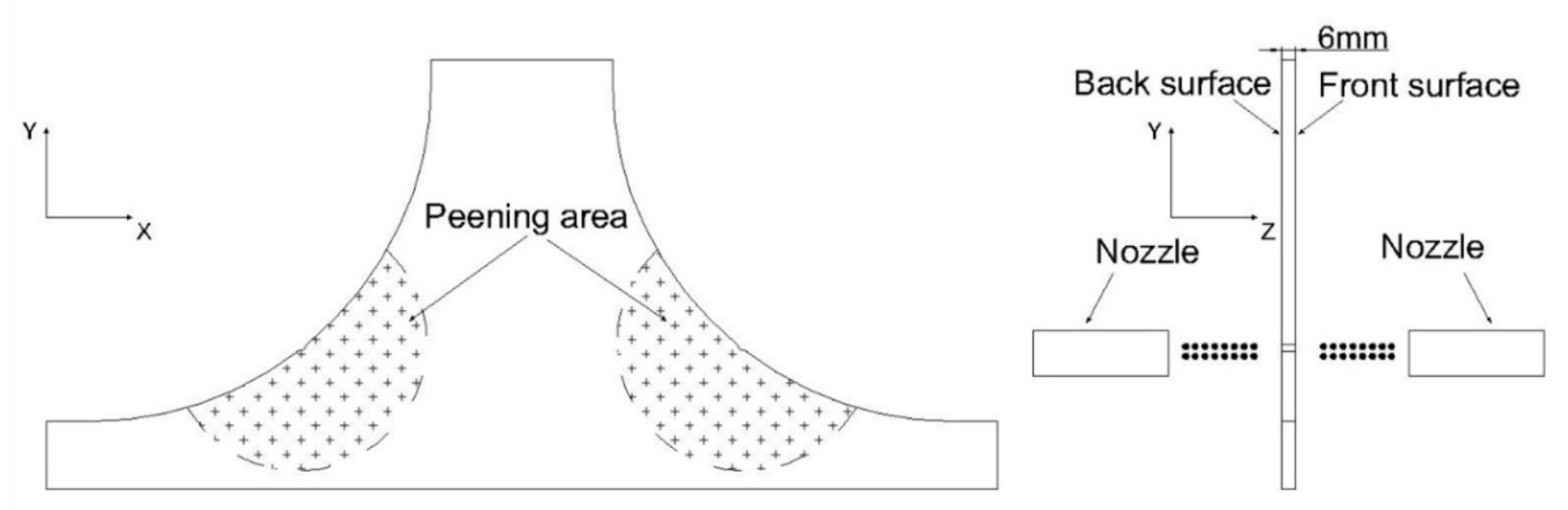
The small–scale experimental specimen and the geometry of the simplified ship hatch corner are shown in Figure 2 and Figure 3a, respectively. In order to control the positions of crack initiation, two arc notches with smooth transition were set on the free edges at specific locations individually. The geometry of the arc notch is shown in Figure 3c while the corresponding location of the arc origination point is demonstrated in Figure 3b. These notches can be regarded as prefabricated defects, which could cause stress concentration. Therefore, the initiation area of the crack can be observed conveniently as can the measurement of the residual stress field’s variation at a specific location. The model is composed of two parts: one is the foundation support of the T section, an opening made at the web to prevent the web bulking during the fatigue tests, and the other is the ship hatch corner specimen which is welded to the panel and welded with the U–shaped chuck symmetrically on both sides of the upper end.
The material of the specimen in this test was Q235B steel. For ascertaining the related parameters of material performance accurately, a series of static tensile tests were carried out as well. The model of the static tensile specimen is shown in Figure 4, and the test procedures were conducted according to GB/T 228.1(2010) [36]. The related parameters of material properties measured in the static tensile test are listed in Table 1. All the specimens were cut from the corresponding 6 mm thick plate by laser cutting directly.

2.2. SP Treatment

SP treatments were carried out on ship hatch corner specimens by air blast SP equipment. Cast steel shots S110, S230, S280, and S330 were used individually for different specimens with the same peening pressures of 3 bar and a constant media flow rate of 25 kg/min. The mean diameters of shots (MDS) were 0.3 mm (S110), 0.6 mm (S230), 0.8 mm (S280), and 1.0 mm (S330), respectively. The diameter of the peening nozzle was 20 mm, while the distance from the peening nozzle to the specimen surface was about 50 mm. The nozzle was kept perpendicular to the surface of the specimen. The peening area included the specific area around both the left and right arc notches on the front and back surfaces, as shown in Figure 5. The peening time was 90 s and the peening coverage was close to 100% in all specimens. Both the left and right peening areas on the front and back surfaces of the specimen were treated with the same PI. Table 2 shows the different SP parameters for hatch corner specimens. Three specimens were processed corresponding to each SP treatment group. All five groups of specimens add up to a total of 15 specimens. All the specimens were conducted with cyclic fatigue tests, and the first specimen of each group was conducted with surface roughness measurement and residual stress relaxation measurement.

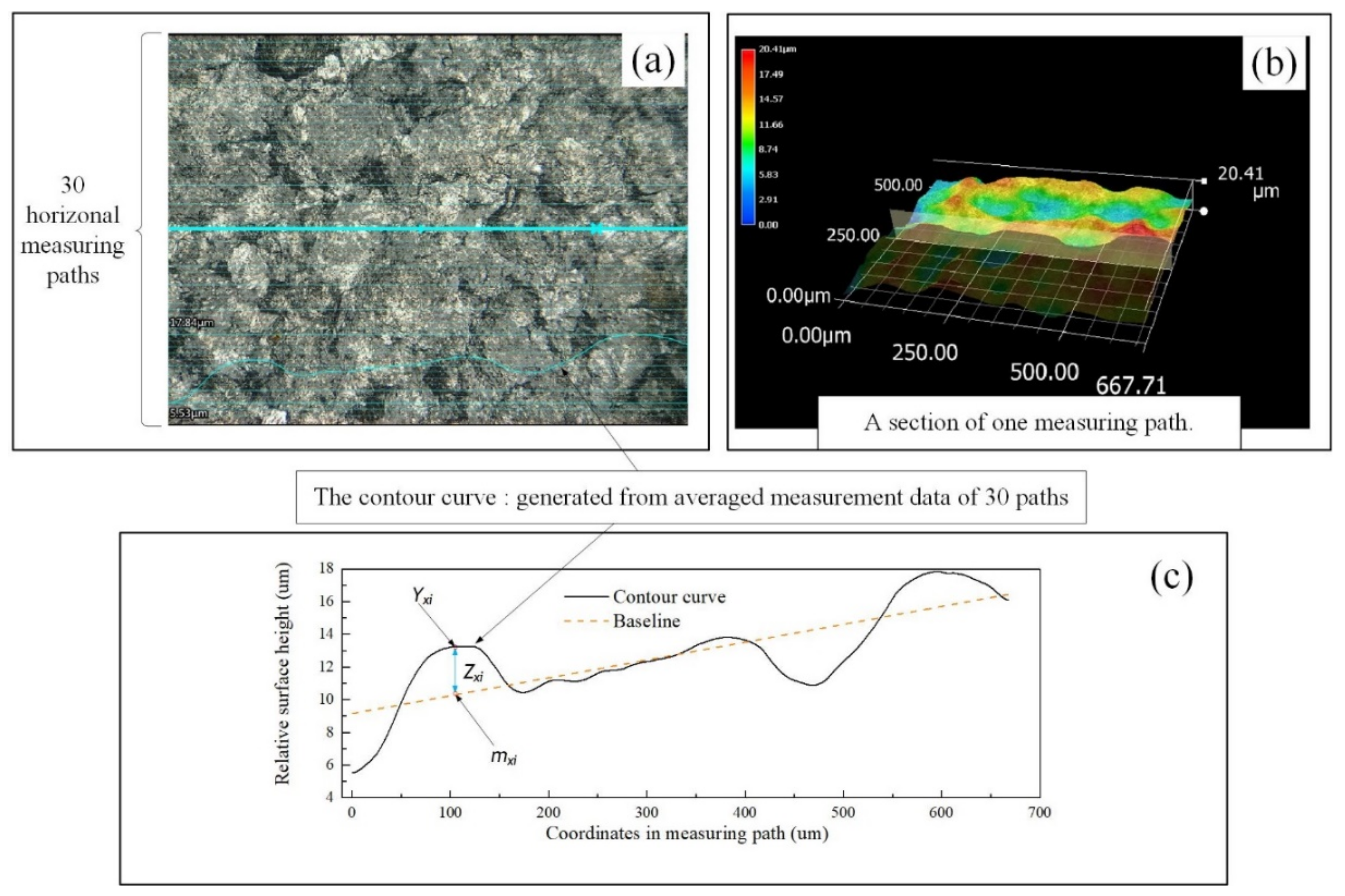
2.3. Surface Roughness Measurement

In order to investigate the effect of SP on specimens, surface topography measurements were performed by using a Keyence 3D microscope. The first specimen of each group is conducted with surface roughness measurement. Thus, the heights of fluctuations in the horizontal and vertical directions of specimens’ surfaces could be measured. Each direction generated a contour curve by data averaging from 30 paths, as shown in Figure 6. Since Ra could be measured directly by the microscope, a program was written based on ISO 4287–2010 [37], which is commonly used in the calculation of Ra. The calculation method of Ra is briefly introduced as follows: The baseline is a line with the smallest sum of squares of the distance from each point on the contour curve to the corresponding point on the contour curve, which is generated by using the least square method. Ra is extracted as follows
R a = 1 N | Y x i m x i | N = 1 N | Z x i | N
where Yxi is the measured value on the contour curve, mxi is a value of the corresponding point on the baseline, Zxi is the absolute value of the distance between Yxi and mxi, and N is the total number of points on the contour curve.

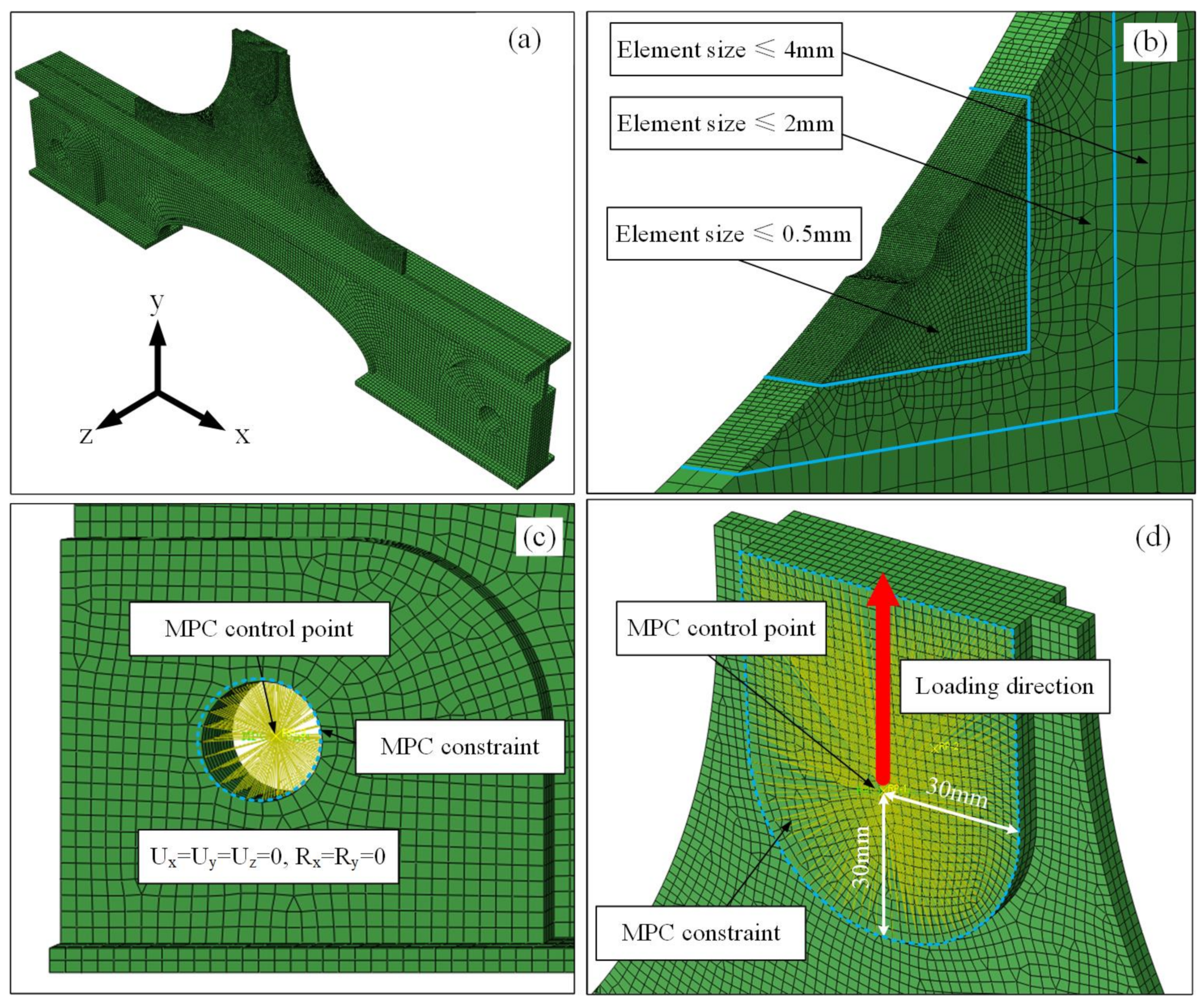
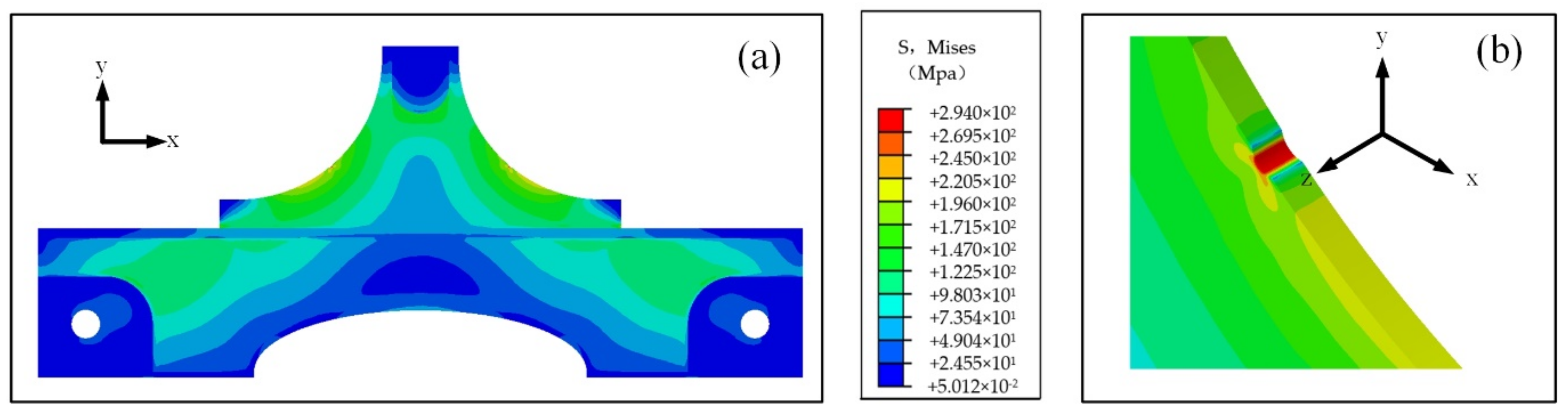
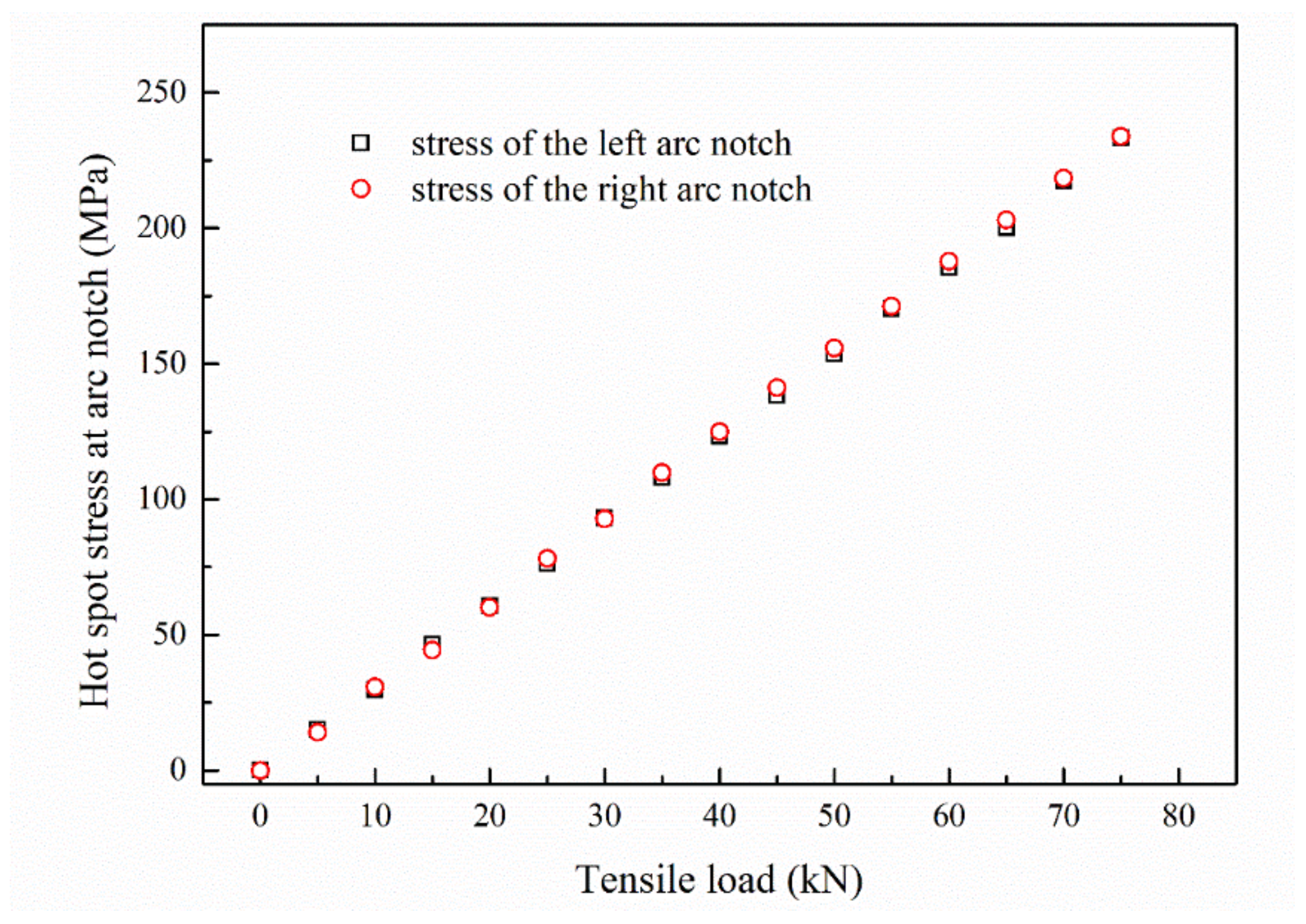
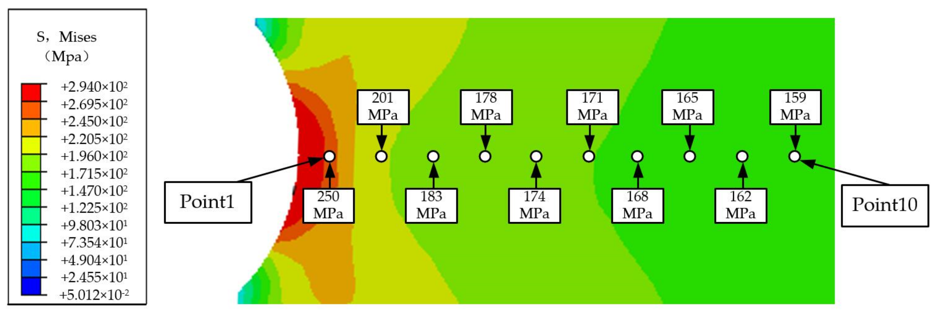
2.4. Finite Element Method (FEM) Analysis

FEM analysis was performed in order to verify the effectiveness of the arc notch design. The finite element model contained 973,456 elements including two element types, C3D8R and C3D4, as shown in Figure 7a. Moreover, the gradually refined transition method was adopted for the arc notch region, and the final element size near the arc notch was not more than 0.5 mm, as shown in Figure 7b. The material properties of the corresponding Q235B were ascertained by the static tensile test and shown in Table 1. It is an ideal elastoplastic material without considering the hardening effect of the material.
The boundary conditions of the finite element analysis are as follows: MPC constraints are used on the surface nodes of the fixed holes on both sides of the foundation support, and the MPC control point is the geometric center of the fixed hole, as shown in Figure 7c; the constraint condition is defined as Ux = Uy = Uz = 0, Rx = Ry = 0 (U represents the displacement, R represents the rotation, x, y, and z represent the directions of U and R). MPC constraints were performed on the U–shaped chuck surface nodes on both sides of the loading end. The MPC control point was 30 mm above the centerline of the U–shaped chuck surface, and the load is applied to the MPC control points symmetrically, as shown in Figure 7d.
The loads were increased from 5 kN to 80 kN gradually and the stress distributions of the hull hatch corner model were analyzed as well. Results show that the regions near the two arc notches were always the most serious regions of stress concentration in the whole model no matter how the tensile loads changed. Figure 8 shows the stress distribution of the hatch corner FE model which verifies that the design of the arc notch was effective.

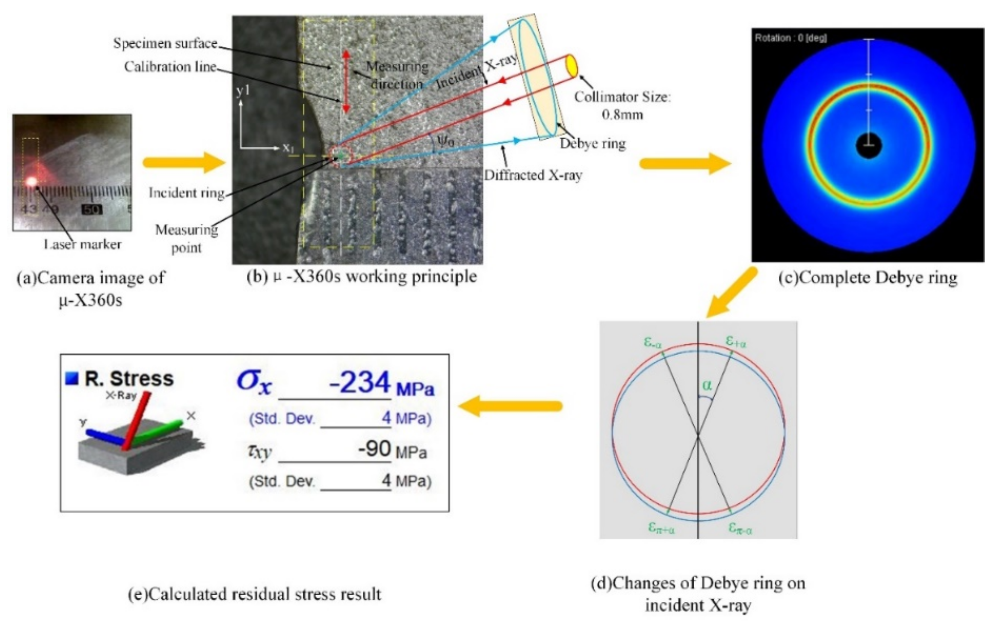
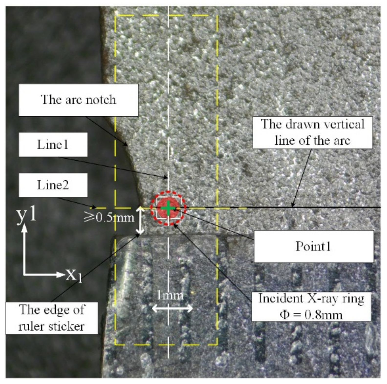
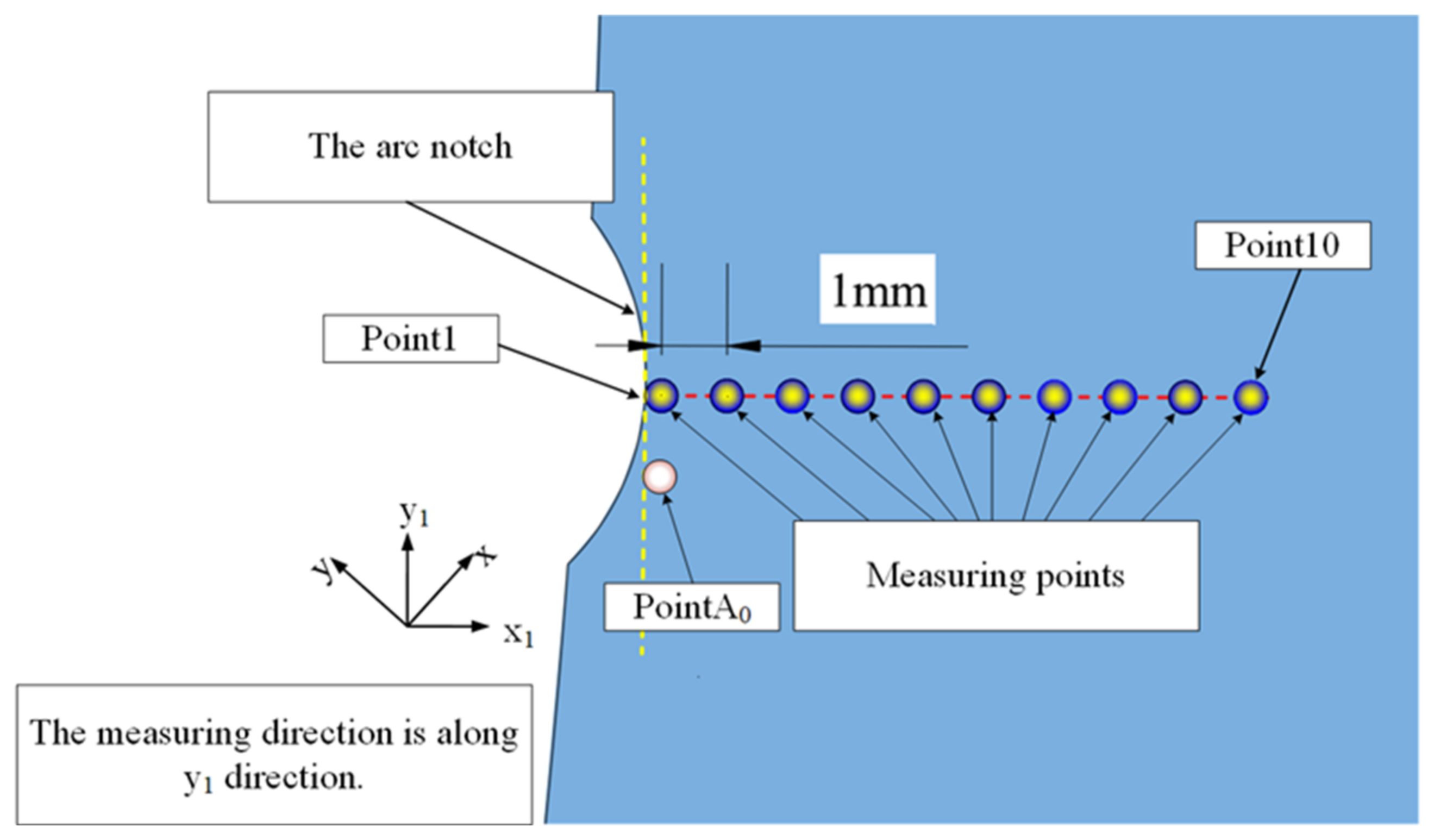
2.5. Residual Stress Measurement

In order to investigate the effect of SP on surface residual stress, a portable X–ray two–dimensional residual stress analyzer µ–X360s (Pulstec® µ–X360s, Hamamatsu–City, Janpan) was used to measure the residual stress at every shot–peened region on each specimen applying the measuring principle of the cosα method [38] (also referred as the single incident angle method). This residual stress analyzer only requires one measurement operation at a specific angle ψ0 to collect the diffraction angle transition of a certain surface, which is used to analyze and obtain the residual stress of the specimen. The schematic diagram of the measuring principle of u–X360s is shown in Figure 9. The angle α is the diffraction angle and the angle η is the complementary angle of α. The optical path of the X–ray and the obtained complete Debye ring are shown in Figure 9b,c, respectively. The angle selected for the Debye ring is presented in Figure 9d. The definition of the parameter a1 can be given as follows:
a 1 = 1 2 [ ( ε α ε π α ) + ( ε α ε π α ) ]
where εα is the strain in the Debye ring, επ−α is the complementary strain, ε−α is the contrary strain.
With the strain εα on the Debye ring, the residual stress can be calculated by the formula given as follows:
σ = E 1 + ν 1 s i n 2 ψ 0 1 s i n 2 η ( a 1 c o s α )
where σ represents the residual stress, E represents the Young’s modulus, and ν denotes the Poisson’s ratio. In this work, the Young’s modulus E and the Poisson’s ratio ν of Q235B steel specimen were determined as 206 GPa and 0.26 according to Section 2.1, respectively.
The first specimen of each group was conducted with residual stress relaxation measurement. In order to show the variation of the residual stress field near the arc notch in detail, some measuring points were defined near the arc notch to measure the dynamic change of the residual stress field. The location of the first measuring point was defined in detail as schematically shown in Figure 10 and the residual stress measuring procedures were as follows: (1) Draw the vertical line of the tangent to the deepest point of the arc notch as the measuring path. (2) Attach a ruler sticker parallel and below at least 0.5 mm to the vertical line to avoid any influence on measurement and align a tick mark on the ruler with the tangent line of the arc notch. (3) Adjust the analyzer to align the green cross in its camera image with the laser mark irradiated on the surface of the specimen to calibrate the measurement distance. (4) Adjust the analyzer to align line1 in the middle of the first two tick marks and overlap line2 in the camera image, the first measuring point is defined as Point1, and then start the measuring program of the analyzer. (5) Move the analyzer 1 mm along the measuring path to the next measuring point and repeat the measuring operation, as shown in Figure 11.
There were a total of ten measurement points, and the residual stresses in the y1 direction (the vertical line of the tangent point) was measured where x and y were the original coordinate system axes. The measuring points were named as Point1–Point10 from the distance to the arc notch in sequence. There was another measuring point named as PointA0 which was 1 mm below Point1 along y1 direction near the arc notch of each specimen. In order to obtain a value of residual stresses in depth before fatigue tests, residual stress measurements in PointA0 were also carried out by iterative electrolytic removal of thin surface layer. Although the measurement path was not necessarily the same as the crack propagation path, it was enough to reflect the changing law of the residual stress field near the arc notch.

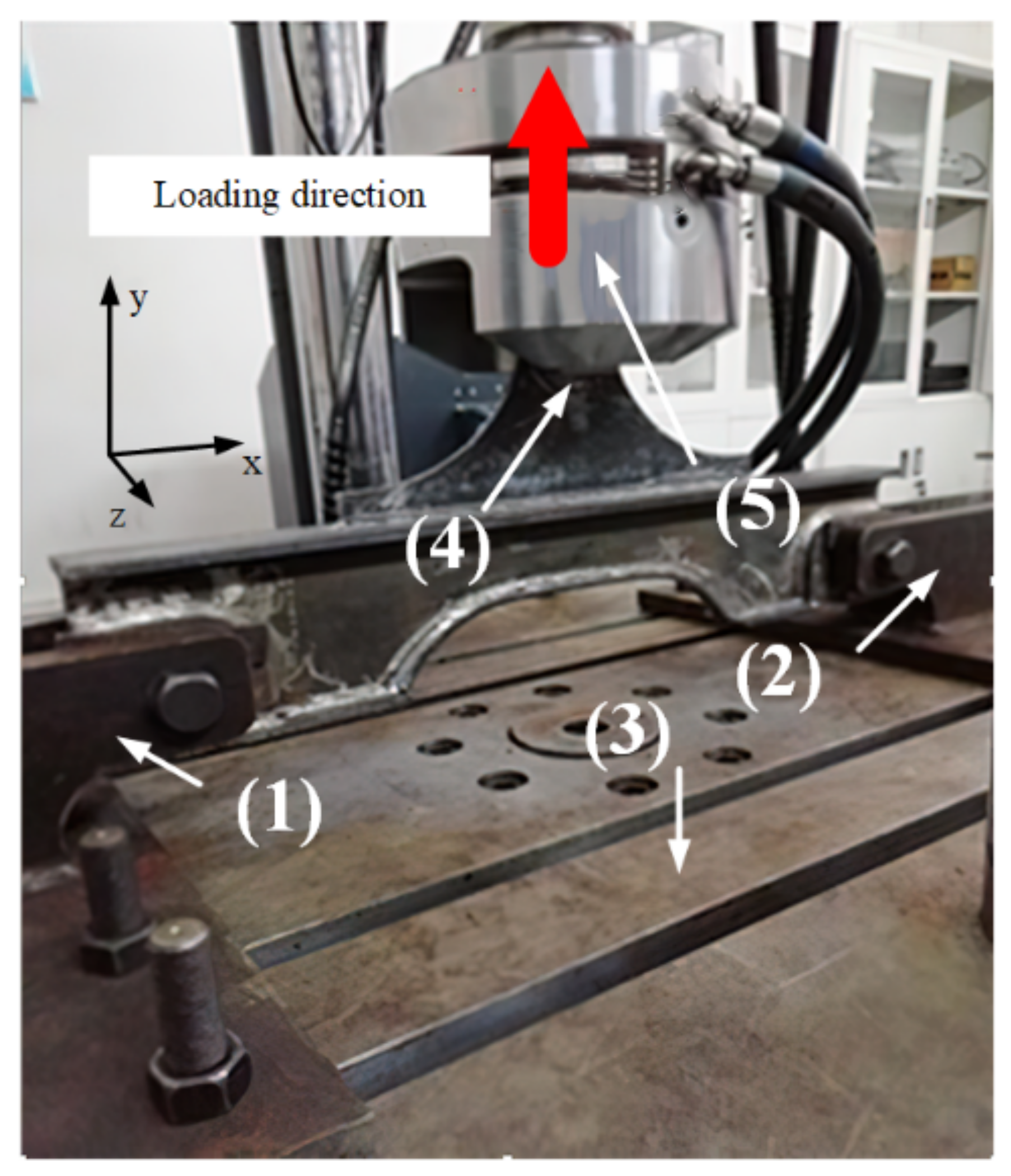
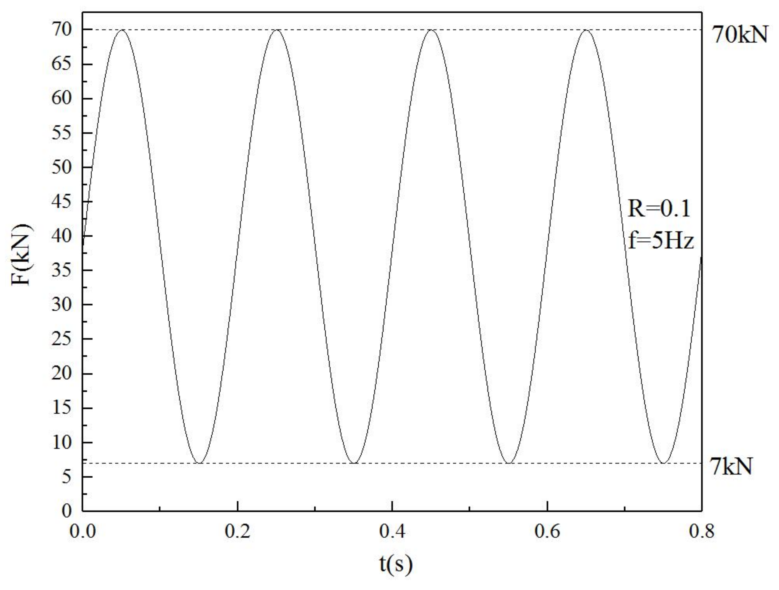
2.6. Static Loading Test and Fatigue Tests

The static loading test and fatigue tests were carried out by the MTS322 250 kN Dynamic Fatigue Testing System at the Ship Structure Laboratory in Wuhan University of Technology (Wuhan, China) under room temperature. Figure 12 shows the installation of the hatch corner test model and the loading direction of tests. Both ends of the hatch corner model were fixed on two ear seats (1) (2) by bolts, and the ear seats were fixed on the test base (3) by bolts; the U–shaped chuck (4) at the upper end of the model was clamped by the fixture (5) of the MTS testing system, and the loading direction is shown in Figure 12. The maximum and minimum stresses near the arc notch were about 218 and 21 MPa with 70 and 7 kN loading measured by strain gauges, respectively. The hot spot stresses at the left and right arc notches are shown in Figure 13.
Fatigue tests were carried out after the static loading test. All the specimens were conducted with constant amplitude cyclic loading of 31.5 kN and the stress ratio was 0.1. The loading frequency was 5 Hz and the loading direction was the same as static loading, as shown in Figure 13. The sinusoidal loading curve is shown in Figure 14. The criterion for judging crack initiation was when the crack was beyond 0.1 mm, and the criterion for judging the fatigue life was the number of fatigue cycle loading when the crack was beyond 1 mm.

3. Results and Discussion

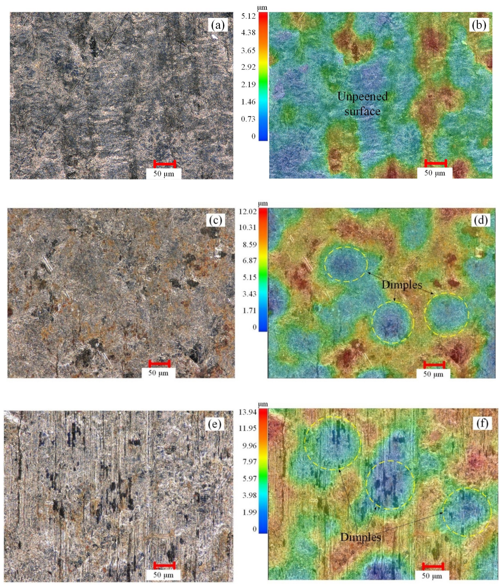
3.1. Surface Roughness and Topography

The changes in surface roughness of specimens caused by the different diameters of shots can be calculated by the method mentioned in Section 2.3. The calculated surface roughness data of specimens are shown in Table 3, which show that SP treatment can increase the surface roughness of peened specimens. The Ra value of unpeened specimen P1 was about 0.07 μm, which was much smaller than the minimum Ra value of peened specimen that appears in P2. The surface roughness increased with a value of MDS. The maximum Ra value appeared in P5, which was peened by the largest shots with diameters of 1 mm.
Figure 15 illustrates the differences in surface topography between each specimen. Compared with the unpeened specimen P1, which had only a few tiny bumps on the surface, all the shot–peened specimens became rough after SP. It can be concluded that the diameter and the depth of a single dimple increase with a value of MDS. The maximum dimple depth appeared in P5 with a value of 16.30 μm, the minimum dimple depth appeared in P2 with a value of 12.02 μm. It was complicated to define the diameter of a dimple due to the difficulties in finding clear boundaries, but it could be estimated based on the color of the cloud in Figure 15. The case of P5 had the greatest diameter of dimple caused by a single shot for SP with the largest MDS.

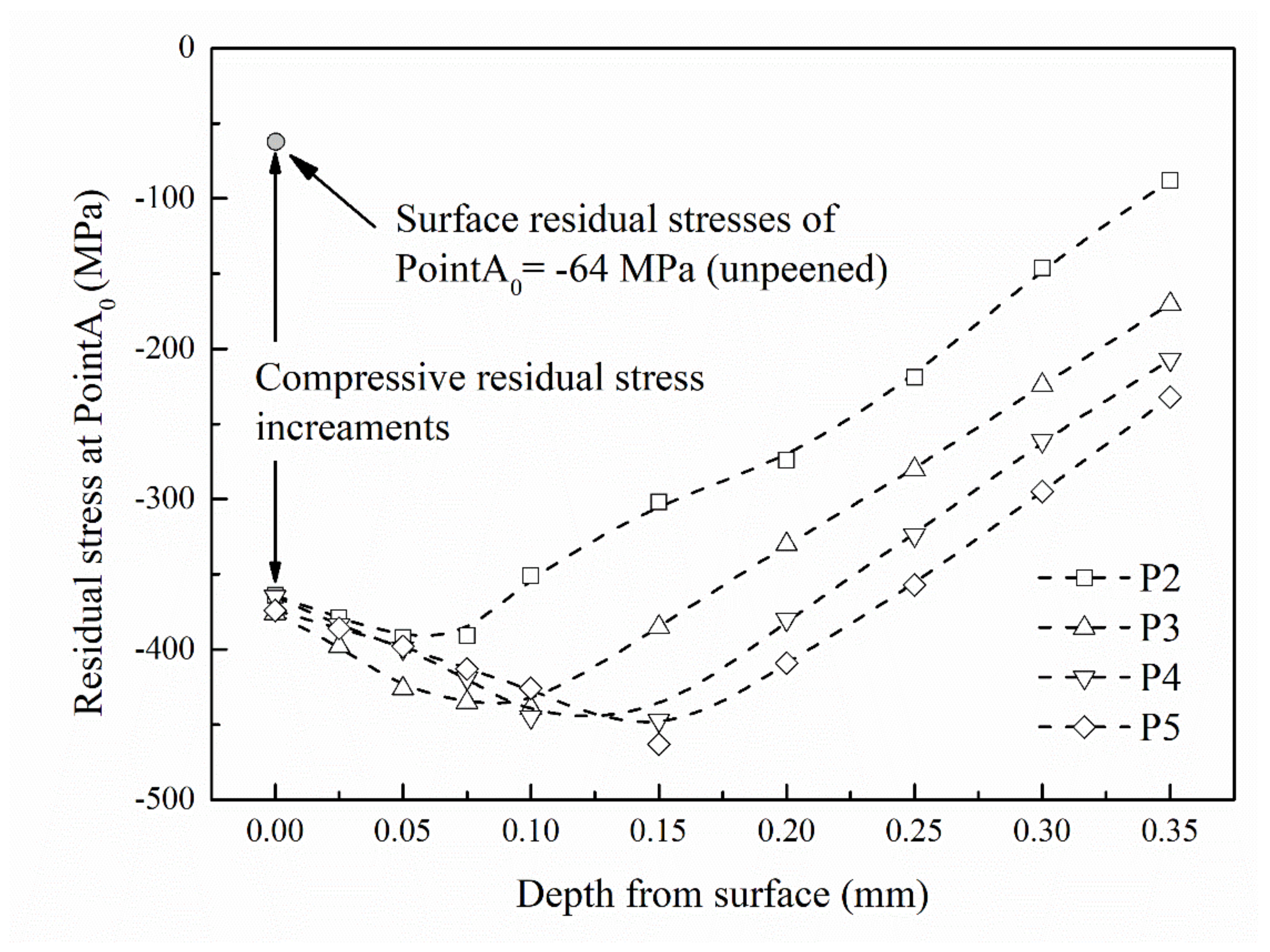
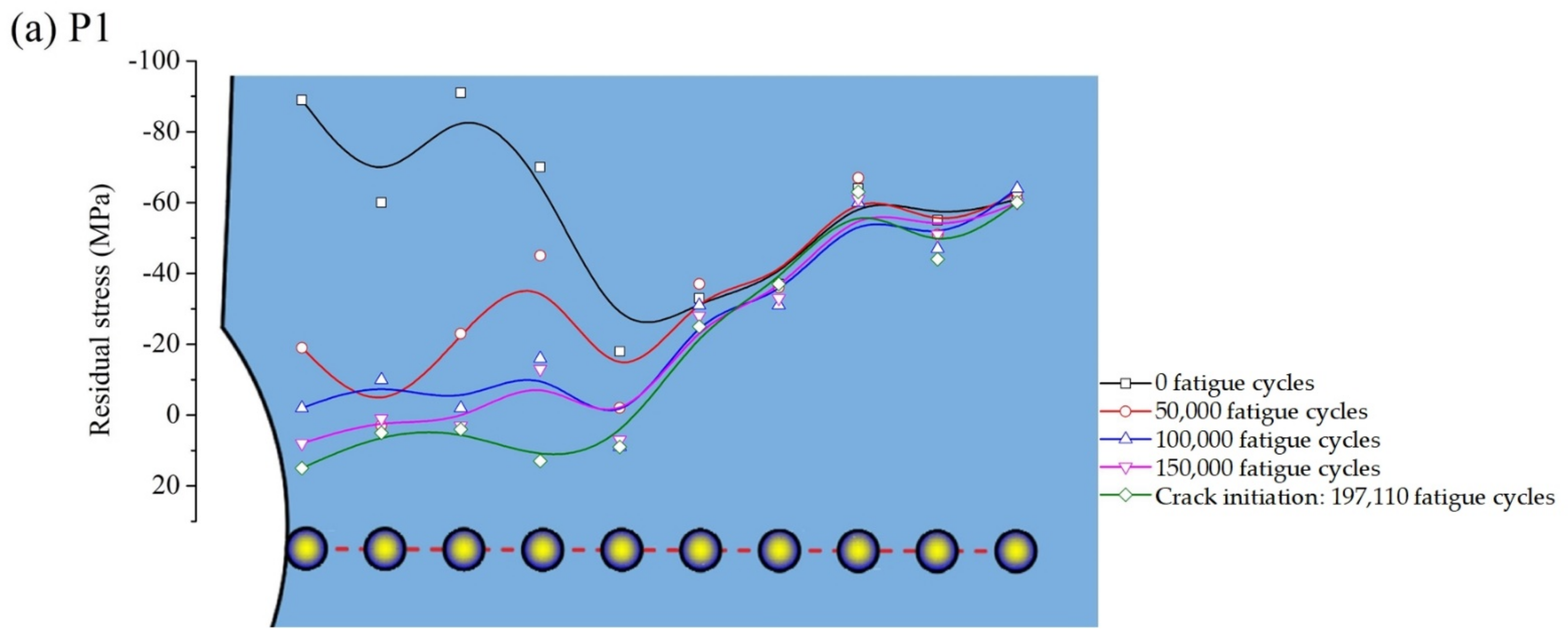
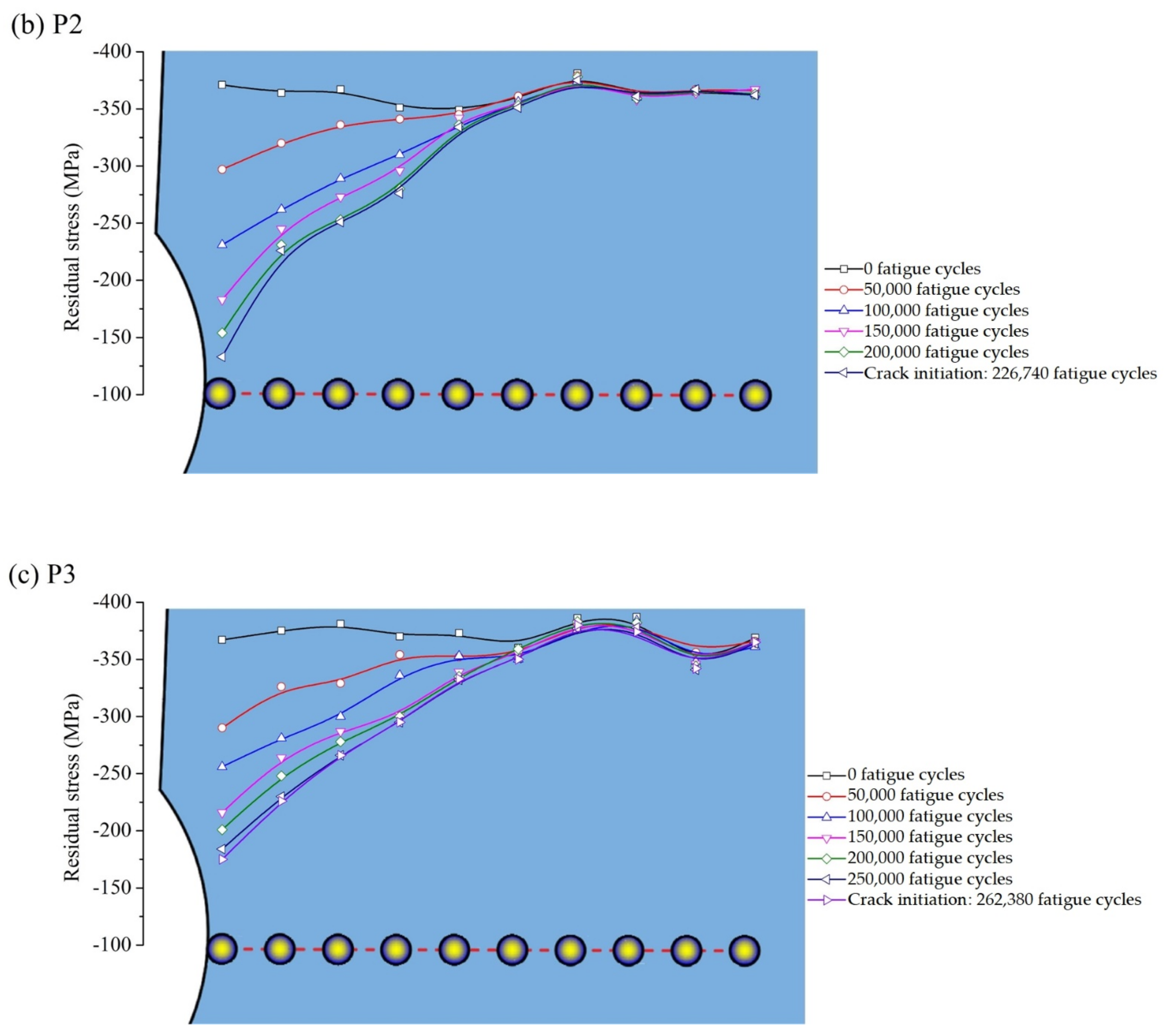
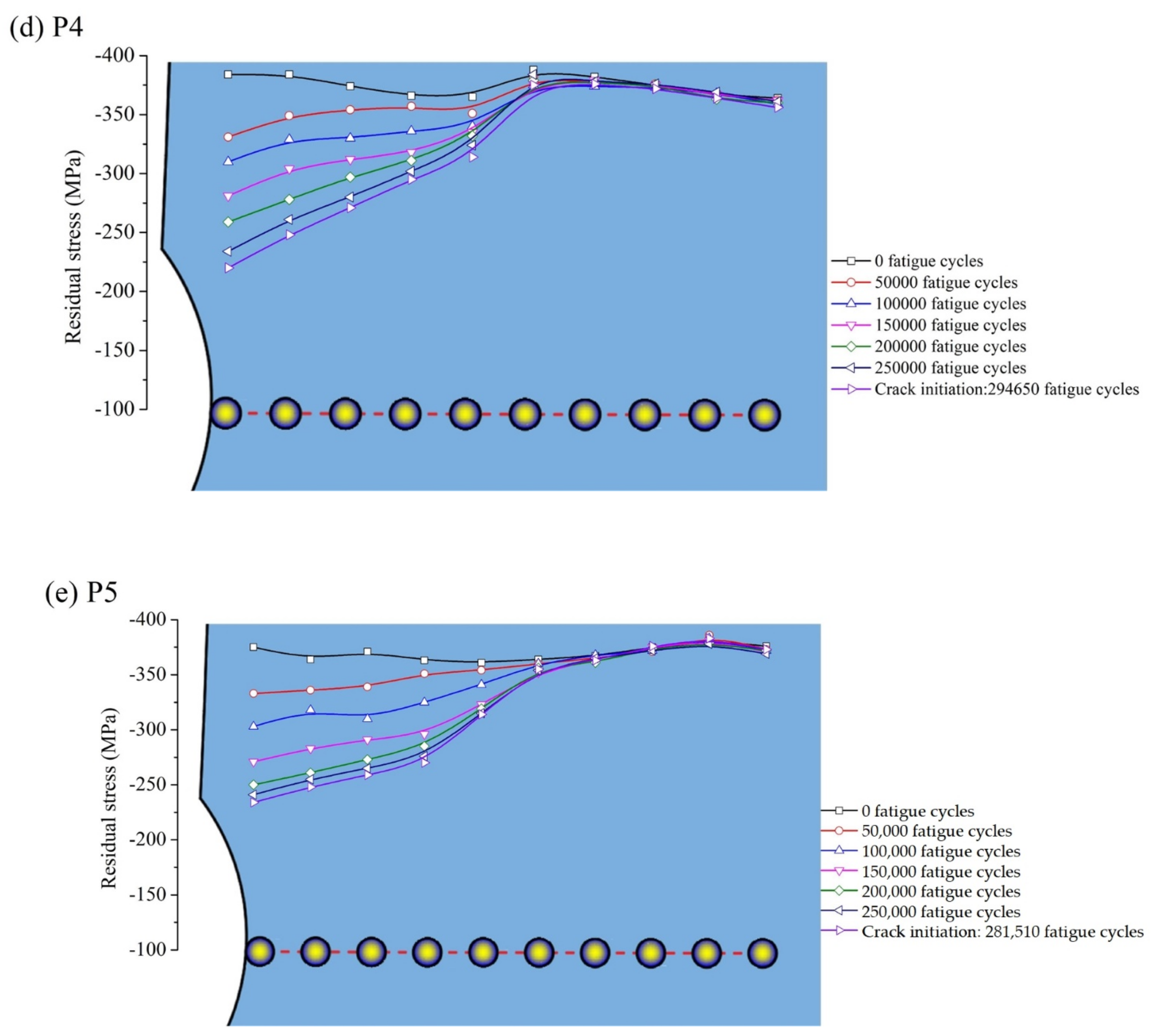
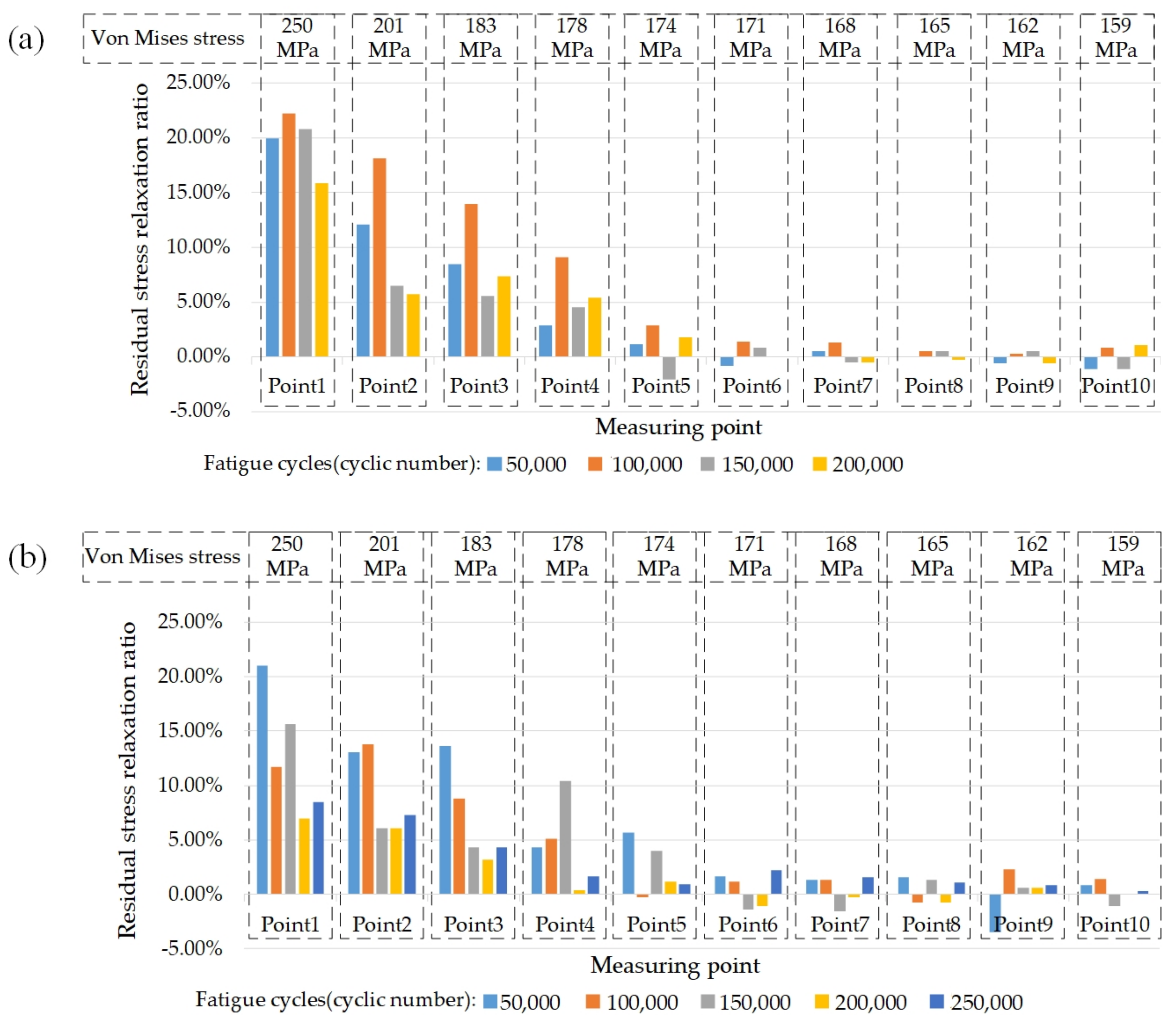
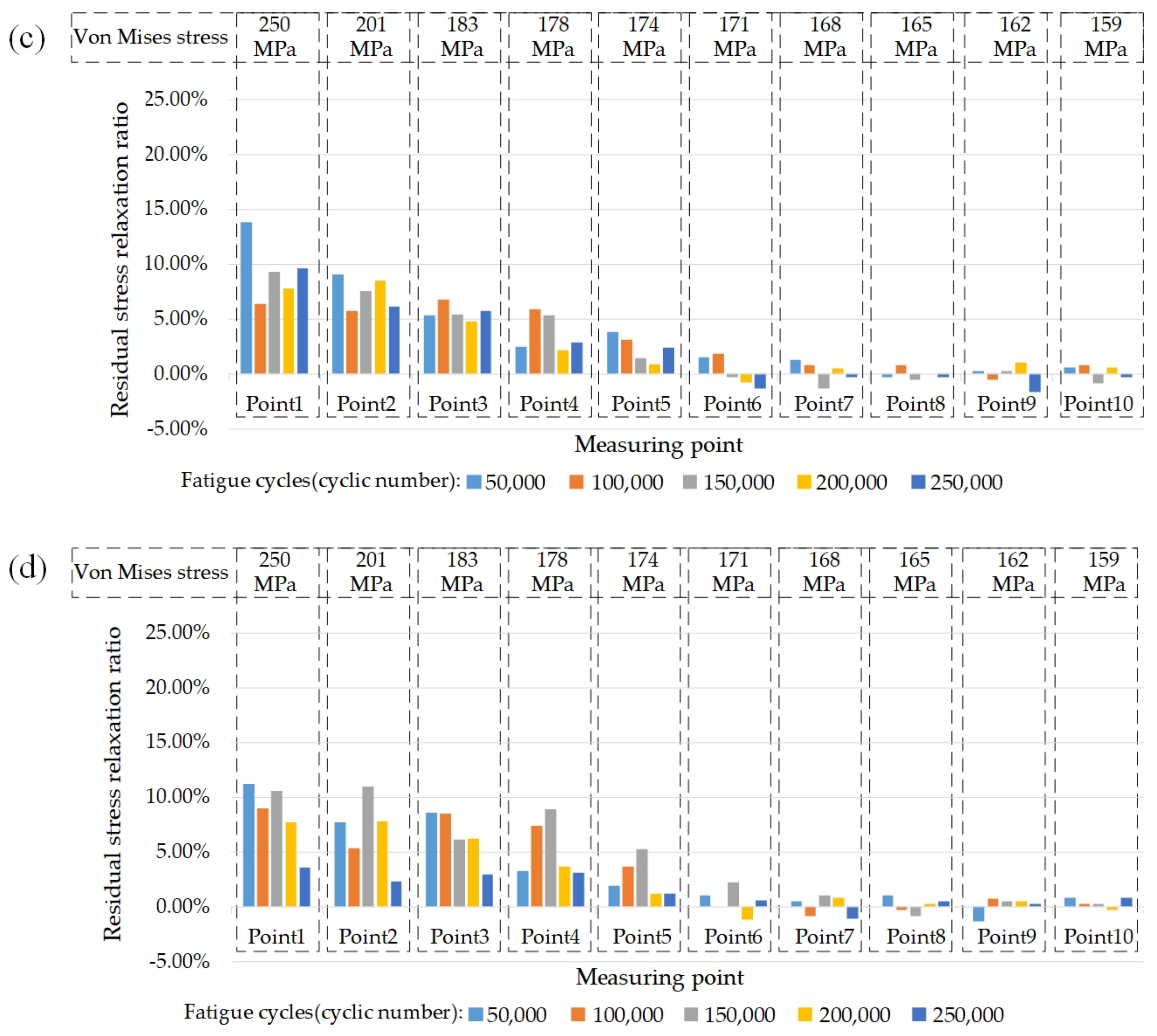
3.2. CRSF and Residual Stress Relaxation

Before residual stress measuring, the peened surface was electrically polished to avoid test error due to an uneven surface. In order to describe the CRSF quantitatively, three characteristic parameters including the surface residual stresses (σRSsurf), the maximum compressive residual stresses (σRSmax), and the depth of σRSmax (δmax), were defined. The specimens were measured for CRSF at PointA0. Figure 16 shows the residual stress depth profiles of PointA0 in the y1 direction. The maximum value of σRSsurf appeared in P3 with a value of −376 MPa, the minimum value of σRSsurf appeared in P2 with a value of −364 MPa, and the values of σRSsurf in the other two specimens were both around 370 MPa. The maximum value of σRSmax appeared in P5 with a value of −463 MPa, and the values of σRSmax in other three specimens increased with MDS from −392 MPa (d = 0.3 mm) to −447 MPa (d = 0.8 mm). It can be seen from Figure 16 that values of δmax in all specimens also increased with MDS from 0.063 mm (d = 0.3 mm) to 0.144 mm (d = 1.0 mm). This phenomenon shows that the values of σRSsurf will not increase with the values of MDS remarkably. Addtionally, the values of σRSmax and δmax in all specimens increased greatly with the values of MDS, which means an increase of PI.
In the process of fatigue loading, the residual stresses were measured at 10 measuring points every 50,000 times of fatigue loading until crack initiation. Figure 17 shows the variety of residual stresses with fatigue loading of five ship hatch corner specimens. For the unpeened specimen P1, it can be seen from Figure 17a that the residual stress at each point on the surface was not uniform compared with other specimens. The residual stress fields began to relax just after the fatigue loading began.
It can be seen from Figure 17 that relaxation rates of the residual stress field were very fast at the first 50,000 cycles of fatigue loading, and then they were reduced to varying degrees. The relaxation rates of the residual stress field gradually decreased from the measuring point from the arc notch. The closer the measuring point to arc notch was, the greater was the relaxation of the residual stress field at this measuring point. During the fatigue loading process, the relaxation rate of the residual stress field decreased gradually.
Although all the specimens were observed to relax the residual stress field, their relaxation rates were not the same under the same fatigue load, which can be reflected by the curve distance in Figure 17. As seen in Figure 17a, the compressive residual stresses of the unpeened specimen P1 reduced by 78.7% (−89 MPa to −19 MPa) after the 1st 50,000 fatigue cycles at Point1 and turns to tensile residual stresses with a value of 15 MPa after crack initiation. As for Figure 17b, the compressive residual stresses of P2 reduced by 19.9% (−371 MPa to −297 MPa) after the first 50,000 fatigue cycles and by 64% (−371 MPa to −133 MPa) at Point1 after the crack initiation. As for Figure 17c, the compressive residual stresses of P3 reduced by 20.9% (−367 MPa to −290 MPa) after the first 50,000 fatigue cycles and by 52.3% (−367 MPa to −175 MPa) at Point1 after the crack initiation. As for Figure 17d, the compressive residual stresses of P4 reduced by 13.8% (−384 MPa to −331 MPa) after the first 50,000 fatigue cycles and by 42.7% (−384 MPa to −220 MPa) at Point1 after the crack initiation. In Figure 17e, the compressive residual stresses of P5 reduced by 11.2% (−375 MPa to −333 MPa) after the first 50,000 fatigue cycles and by 37.6% (−375 MPa to −234 MPa) at Point1 after the crack initiation. After 50,000 fatigue loadings, the residual stress relaxation rate at each point also decreased, but the trend was still similar to before.
Combined with Figure 16 and Figure 17, it can be found that the specimens with greater values of σRSmax and δmax had lower residual stress relaxation rates. Although their surface residual stresses were similar before fatigue loading, they show different “retention capabilities” of residual stress or stability of CRSF during fatigue loading. P5 had the greatest value of σRSmax and δmax, and the remaining residual stresses were the greatest when the crack was initiated and the remaining residual stresses of other specimens decrease with the decrease of MDS. In other words, the specimen with deeper CRSF had better retention capability of surface residual stress.
Figure 18 shows the local stress distribution of numerical analysis results at 70 kN loading and the Von Mises stress of each measuring point. The Von Mises stresses could be alternatively regarded as the amplitude stresses in fatigue loading here. Combined with the residual stress data obtained in X–ray diffraction measurement, the relaxation ratio of the residual stress at each measuring point of shot–peened specimens P2 to P5 could be compared. Comparing the residual stress after every 50,000 fatigue cycles with that before fatigue cycles, the results shown in Figure 19 are the calculated relaxation ratios of the residual stress per 50,000 fatigue cycles. It can be seen that for all the shot–peened specimens, the relaxation of the compressive residual stress was also greater where the stress is greater. As the stress decreased linearly, the relaxation of the compressive residual stress also decreased, but it was nonlinear. Although the specimens P2 to P5 were processed by SP with different MDS, they all showed insensitivity to residual stress relaxation when the stress was below 174 MPa (Point6 and subsequent measurement points). It can be noticed that there was a threshold value of the stress amplitude that allowed the residual stress to relax. When the stress amplitude was lower than the threshold value, regardless of the size of the MDS as well as the number of fatigue cycles, the compressive residual stress barely changed. Combining the experimental data and the FEA results, the threshold value of the stress amplitude should be between 171 MPa and 174 MPa.
The residual stress relaxation ratio of each specimen at each fatigue loading stage were also different. For example, P2 and P3 had large residual stress relaxation ratios in the first and second 50,000 fatigue cycles; the relaxation ratios of P2 after the first and second 50,000 fatigue cycles were about 20% and 22% at Poin1, 12% and 18% at Point2, and 9% and 14% at Point3, respectively; the relaxation ratios of P3 after the first and second 50,000 fatigue cycles were about 21% and 12% at Poin1, 13% and 14% at Point2, and 13% and 9% at Point3 respectively. These two specimens had a great stress relaxation in the early stage (100,000 fatigue cycles) of fatigue loading. By contrast, the relaxation ratios of P4 after the first and second 50,000 fatigue cycles were about 14% and 6% at Poin1, 9% and 6% at Point2, 5% and 7% at Point3, respectively; the relaxation ratios of P5 after the first and second 50,000 fatigue cycles are about 11% and 9% at Poin1, 8% and 8% at Point2, and 3% and 7% at Point3 respectively. Compared with P2 and P3, P4 and P5, which had deeper CRSFs, had better performances in resisting compressive residual stress relaxation. It also can be seen from Figure 19 that nearly all the residual stress relaxation ratios of P4 and P5 were below 10% at all measuring points in every fatigue loading stage.
For the actual design and construction of River–Sea–Going ships, the stress concentration at the corners of the hatch is difficult to avoid, but the stress amplitude should be controlled. It can be found that if the fatigue performances of the hatch corners are expected to be improved by SP treatments, the residual stress relaxation should be considered when local stress is beyond the threshold value. If the stress amplitude at the hatch corner is lower than the stress threshold value of residual stress relaxation, the residual stress field will barely change. It is also a feasible method to change the parameters of SP treatment to introduce a deeper residual stress field into the surface of the hatch corner structure to reduce the residual stress relaxation ratio and keep the CRSF more stable in fatigue loading.

3.3. Fatigue Life

Table 4 shows the fatigue life and other characteristic parameters of all specimens, including not only the specimens for residual stress relaxation research but also the other two specimens in the same SP treatment group that were conducted with fatigue tests. In Table 4, Nin represents the crack initiation life (crack from 0.0 mm to 0.1 mm), ΔNin represents the ratio of crack initiation life increment, Npr represents the crack propagation life (0.1 mm to 1 mm), ΔNpr represents the ratio of crack propagation life increment, Nf represents fatigue life (crack from 0.0 mm to 1 mm), and ΔNf represents the ratio of fatigue life increment, where all the increments are based on the comparison with P1. It can be seen that the fatigue life of P1 without SP was about 214,550 in the first fatigue test. The increment comparisons of subsequent data were based on the first fatigue test data of the P1 specimen. The maximum fatigue life appeared at the P4 specimen in the third fatigue test with a value of 347,710 when MDS was 0.8 mm. It can be concluded through Table 4 that all the SP treatments can improve fatigue lives of ship hatch corner specimens greatly.
Specifically, the average of ΔNins within each group were 13.3% (P2), 33.5% (P3), 57.2% (P4), and 48.3% (P5); the averages of ΔNprs within each group were 18.2% (P2), 36.0% (P3), 60.7% (P4), and 55.9% (P5); the average of ΔNfs within each group were 13.7% (P2), 33.7% (P3), 57.5% (P4), and 48.9% (P5). Although the fatigue life extension of each group showed differences for a single specimen, it can be found through the comparison between the groups that when the PI increased, the differences in the ΔNfs within each group were gradually reduced. It can be analyzed by the comparison of ΔNin of each group that in the crack initiation stage, shot peening had a very good effect on the suppression of the crack initiation. SP also suppressed the crack growth rate in the crack propagation stage, which can be analyzed by the comparison of ΔNpr of each group. ΔNin, ΔNpr, and ΔNf all increased initially with the increase of MDS (when d= 0.3 mm, 0.6 mm and 0.8 mm), but when d = 1.0 mm, the increments of ΔNin, ΔNpr, and ΔNf were not obvious compared with those when d = 0.8 mm, and some of the data even decreased. This means that prolonging the fatigue life of the hatch corner by only increasing the MDS has a limited effect. This can be caused by the excessive surface roughness caused by the increase in MDS. P4 and P5 both had better residual stress stability, and thus they had larger ΔNin values than P2 and P3. With the increase of MDS, the crack initiation life and fatigue life both showed an increasing trend. It can be seen from this that the fatigue lives of P2, P3, and P4 all increased with the increase of σRSmax and δmax values. At the same time, the effective residual stress at the arc notch at the crack initiation time also increased with the increase of σRSmax and δmax values. On the other hand, P5 had larger σRSmax and δmax values than P4 and its remaining effective residual stress when the crack initiated was also greater, but its fatigue life was not improved; however, it was reduced. The reason for this may be that P5 has a larger Ra than P4. Although the remaining effective residual stress on the surface is slightly larger than that of P4, it is not enough to offset the effect of surface defects caused by the larger Ra value, so the fatigue life of P5 is slightly smaller than that of P4. For P5, which has larger σRSmax and δmax, the influence of surface roughness was even more severe. When increasing the PI of SP treatments, a value of Ra would also increase. If Ra is beyond a certain value, the limited improvement of CRSF cannot offset the negative effect of increased surface roughness on surface integrity. This is manifested in the local defects caused by the increase of surface micro–damage, and the micro–stress concentration, which makes it easier for cracks to initiate and propagate at the defects.
It is generally believed that the surface compressive residual stress has an important influence on the fatigue performance of the structure. In fact, the surface residual stress changes during the fatigue load, especially in the initial stage of the fatigue loading, it has a large relaxation rate. Under the fatigue loading, the relaxation performance of the residual stress field of different specimens was different and closely related to the characteristic parameters of CRSF. The surface residual stress relaxation rate of the specimen with deeper CRSF was slower, and the surface compressive residual stress before the crack initiation was larger, the crack initiation suppression effect was better, and the crack growth rate could also be slowed down.
In the aim of improving fatigue lives of hatch corners in the River–Sea–Going ship by SP treatment, both residual stress relaxation and surface roughness should be considered. It can be concluded that when the parameters of SP treatment are correctly chosen, the fatigue life of the hatch corner can be improved greatly. In terms of optimizing shot peening parameters, the approach to reduce the increase in roughness induced by shot peening intensity should be investigated. On the other hand, the assessment of the residual stress stability of the hatch corners should be combined with the actual load of the River–Sea–Going ship.

4. Conclusions

Given the fact that there is almost no application of fatigue improvement by SP treatment in the ship engineering field, this paper illustrates the relationship between the stress relaxation and fatigue life of the actual ship hatch corner structure in the shot–peened region under a constant amplitude fatigue load, and shows the sensitivity of the residual stress relaxation at different positions during the cyclic fatigue loading. Moreover, it provides an approach to improve the fatigue strength and life of ship hatch corner structures by SP treatment and a procedure for evaluating the fatigue life of the actual ship hatch corner structure after SP. The effect of SP on the fatigue life of ship hatch corner specimens made of Q235B steel was investigated at a stress ratio of 0.1 and cyclic loading amplitude of 31.5 kN. SP intensity was changed by changing the mean diameter of shots of SP. The surface roughness, residual stress, and fatigue life tests were carried out on ship hatch corner specimens. The surface residual stresses were measured with the aim of analyzing the residual stress variation at different locations in each specimen during cyclic loading. The residual stress relaxation ratios of different specimens at different locations were compared and analyzed. The following conclusions have been reached:
  • Introducing compressive residual stress into the surface layer by SP is an effective method to prolong the fatigue life of the ship hatch corner. The larger the values of σRSmax and δmax, the slower the residual stress field relaxation rates are under cyclic loading.
  • It was found that the compressive residual stress near surface layer is beneficial to both the initiation life and the propagation life of fatigue crack. Compared with the unpeened specimen, the increments of crack initiation life are about 13.3%, 33.5%, 57.2%, and 48.3% on average, and the increments of crack propagation lives, are about 18.2%, 36.0%, 60.7%, and 55.9% with MDS of 0.3 mm, 0.6 mm, 0.8 mm, and 1.0 mm, respectively.
  • The magnitude of residual stress relaxation does not decrease linearly with the linear decrease of stress under the same number of cyclic loading. When the stress is less than the threshold value for the relaxation of the residual stress, the residual stress on the surface of the structure will not relax. Specimens P4 and P5 with deeper CRSFs have better residual stress stabilities and better fatigue performances compared to P2 and P3.
  • In practical engineering applications, increasing SP intensity can increase the values of σRS max and δmax in the compressive residual stress field, as well as the residual stress stability. Moreover, it also increases the surface roughness, which has adverse effects on the fatigue life of the hatch corner specimen. Therefore, the effect of residual stress field and surface roughness should be considered comprehensively in the SP process.
Results of this research prove that shot peening is feasible in improving the fatigue performance of ship hatch corner structures. In order to achieve better fatigue property improvement, residual stress relaxation and surface roughness should be taken into consideration comprehensively. Residual stress relaxation is highly concerned with the depth of CRSF and the stress amplitude. Increasing the depth and value of CRSF via increasing peening intensity can reduce the residual stress relaxation at the same stress amplitude in practical application.

Author Contributions

Conceptualization, J.G., W.W., and Z.G.; Methodology, J.G., Z.G., and Z.W.; writing–original manuscript, Z.G. and Y.W.; writing–review and editing, Y.W. and Z.W. All authors have read and agreed to the published version of the manuscript.

Funding

This research was funded by the National Natural Science Foundation of China (No. 51879208) and the National Scientific Research Project of the High–tech Ship of China (No.2014[493]). The authors are grateful to all the staff of Green & Smart River–Sea–Going Ship, Cruise and Yacht Research Center for supporting this work.

Conflicts of Interest

The authors declare no conflict of interest.

Abbreviations

SPShot peening
MDSMean diameter of shots
dValue of MDS
PIPeening intensity
CRSFCompressive residual stress field
FEMFinite element method
FEAFinite element analysis
UxDisplacement in the x direction
UyDisplacement in the y direction
UzDisplacement in the z direction
RxRotation in the x direction
RyRotation in the y direction
σRS maxMaximum residual stress in depth
σRSsurfSurface residual stress
δmaxDepth of σRS max
RaSurface roughness
NNumbers of points on the contour curve
YxiValue of contour curve
mxiValue of baseline
ZxiThe absolute value of the distance between Yxi and mxi
EYoung’s modulus
RmUltimate tensile stress
σsYield stress
νPoisson’s ratio
δElongation
αDiffraction angle
ηThe complementary angle of α
a1Intermediate parameters
εαStrain in the Debye ring
επ−αComplementary strain
ε−αContrary strain
ψ0Operating angle of the X–ray analyzer
NinCrack initiation life
ΔNinThe ratio of crack initiation life increment
NprCrack propagation life
ΔNprThe ratio of crack propagation life increment
NfFatigue life
ΔNfThe ratio of fatigue life increment

References

  1. IACS. Common Structural Rules for Bulk Carriers; IACS: London, UK, 2006. [Google Scholar]
  2. CCS. Guidelines for Fatigue Strength Assessment of Hull Structures; CCS: Edmond, OK, USA, 2015. [Google Scholar]
  3. Guoqing, F.; Hao, S.; Dongping, L.; Hui, L. The stress combination method for the fatigue assessment of the hatch corner of a bulk carrier based on equivalent waves. J. Mar. Sci. Appl. 2012, 11, 68–73. [Google Scholar]
  4. Selle, H.; Doerk, O.; Scharrer, M. Global strength analysis of ships with special focus on fatigue of hatch corners. In MARSTRUCT Book Series; Taylor Francis Group: Abingdon, UK, 2009; pp. 255–260. [Google Scholar]
  5. Yong, H.X.; Wei, W.; Heng, Z. Fatigue strength study on different structure type of hatch corner. Adv. Mat. Res. 2011, 233, 2580–2583. [Google Scholar]
  6. Xu, X.; Augello, R.; Yang, H. The generation and validation of a CUF–based FEA model with laser–based experiments. Mech. Adv. Mater. Struct. 2019, 1–8. [Google Scholar] [CrossRef]
  7. Xu, X.; Yang, H.; Augello, R.; Carrera, E. Optimized free–form surface modeling of point clouds from laser–based measurement. Mech. Adv. Mater. Struct. 2019, 1–9. [Google Scholar] [CrossRef]
  8. Carrera, E.; Pagani, A.; Augello, R. Evaluation of geometrically nonlinear effects due to large cross–sectional deformations of compact and shell–like structures. Mech. Adv. Mater. Struc. 2020, 27, 1269–1277. [Google Scholar] [CrossRef]
  9. Jiancheng, L.; Yongning, G. A Study on Stress Concentration at Hatch Corner for Ship with Large Openings. Ship Eng. 2000, 6, 9–12. [Google Scholar]
  10. Petronic, S.; Colic, K.; Dordevic, B.; Milovanovic, D.; Burzic, M.; Vucetic, F. Effect of laser shock peening with and without protective coating on the microstructure and mechanical properties of Ti–alloy. Opt. Laser. Eng. 2020, 129, 106052. [Google Scholar] [CrossRef]
  11. Hackel, L.; Dane, C. Reliable laser technology for laser peening applications. In Proceedings of the 2012 Conference on Lasers and Electro–Optics (CLEO), San Jose, CA, USA, 6–11 May 2012; pp. 1–2. [Google Scholar]
  12. Leap, M.J.; Rankin, J.; Harrison, J.; Hackel, L.; Nemeth, J.; Candela, J. Effects of laser peening on fatigue life in an arrestment hook shank application for Naval aircraft. Int. J. Fatigue 2011, 33, 788–799. [Google Scholar] [CrossRef]
  13. Rajan, S.S.; Swaroop, S.; Manivasagam, G.; Rao, M.N. Fatigue life enhancement of titanium alloy by the development of nano/micron surface layer using laser peening. J. Nanosci. Nanotechnol. 2019, 19, 7064–7073. [Google Scholar] [CrossRef] [PubMed]
  14. Kasra, G.; Rakesh, R.; Scott, W.; Ayhan, I. Fatigue strength improvement of aluminum and high strength steel welded structures using high frequency mechanical impact treatment. Proc. Eng. 2015, 133, 465–476. [Google Scholar]
  15. Harati, E.; Svensson, L.; Karlsson, L.; Widmark, M. Effect of high frequency mechanical impact treatment on fatigue strength of welded 1300MPa yield strength steel. Int. J. Fatigue 2016, 92, 96–106. [Google Scholar] [CrossRef]
  16. Jan, F.; Volker, H.; Majid, F. High frequency mechanical impact treatment (HFMI) for the fatigue improvement: Numerical and experimental investigations to describe the condition in the surface layer. Weld. World 2016, 60, 749–755. [Google Scholar]
  17. Zhenwen, Y.; Qi, L.; Jiahui, W.; Zongqing, M.; Ying, W.; Dongpo, W. Effect of ultrasonic impact treatment on the microstructure and mechanical properties of diffusion–bonded TC11 alloy joints. Arch. Civ. Mech. Eng. 2019, 19, 1341–1441. [Google Scholar]
  18. Kahraman, F. Surface layer properties of ultrasonic impact–treated AA7075 aluminum alloy. Proc. Inst. Mech. Eng. Part B J. Eng. 2018, 232, 2218–2225. [Google Scholar] [CrossRef]
  19. Bolin, H.; Haipeng, D.; Mingming, J.; Kang, W.; Li, L. Effect of ultrasonic impact treatment on the ultra high cycle fatigue properties of SMA490BW steel welded joints. Int. J. Adv. Manuf. Technol. 2018, 96, 1571–1577. [Google Scholar]
  20. Chuan, L.; Yi, Y.; Xiaohua, C.; ChunJing, W.; Yong, Z. Residual stress in a restrained specimen processed by post–weld ultrasonic impact treatment. Sci. Technol. Weld. JOI 2019, 24, 1–7. [Google Scholar]
  21. Mohammad, A.O.; Hamzah, M.M.; Faris, M.A.; Mohammad, A. Enhancing the surface hardness and roughness of engine blades using the shot peening process. Int. J. Min. Met. Mater. 2019, 26, 999–1004. [Google Scholar]
  22. Lukáš, F.; Werner, D.; Werner, E.; Thomas, K.; Michael, T.; Christoph, C. Effect of shot peening on residual stresses and crack closure in CVD coated hard metal cutting inserts. Int. J. Refract. Met. H 2019, 82, 174–182. [Google Scholar]
  23. Bag, A.; Delbergue, D.; Ajaja, J.; Bocher, P.; Levesque, M.; Brochu, M. Effect of different shot peening conditions on the fatigue life of 300 M steel submitted to high stress amplitudes. Int. J. Fatigue 2020, 130, 105271–105274. [Google Scholar] [CrossRef]
  24. Martín, V.; Vázquez, J.; Navarro, C.; Domínguez, J. Effect of shot peening residual stresses and surface roughness on fretting fatigue strength of Al 7075–T651. Tribol. Int. 2020, 142, 106004. [Google Scholar] [CrossRef]
  25. Gan, J.; Sun, D.; Wang, Z.; Luo, P.; Wu, W. The effect of shot peening on fatigue life of Q345D T–welded joint. J. Constr. Steel. Res. 2016, 126, 74–82. [Google Scholar] [CrossRef]
  26. Wohlfahrt, H. The influence of peening conditions on the resulting distribution of residual stress. In Proceedings of the Second International Conference on Shot Peening, Chicago, IL, USA, 14–17 May 1984; pp. 316–331. [Google Scholar]
  27. Maiya, P.S. Geometrical characterization of surface roughness and its application to fatigue crack initiation. Mater. Sci. Eng. 1975, 21, 57–62. [Google Scholar] [CrossRef]
  28. Novovic, D.; Dewes, R.C.; Aspinwall, D.K.; Voice, W. The effect of machined topography and integrity on fatigue life. Int. J. Mach. Tool. Manuf. 2004, 44, 125–134. [Google Scholar] [CrossRef]
  29. Ruihong, L.; Daoxin, L.; Wei, Z.; Xuan, L.; Mingjie, Q.; Mingli, X. Influence of Shot Peening and Surface Integrity on the Fatigue Properties of 300M Steel. Mech. Sci. Tech. Aerosp. Eng. 2011, 9, 1418–1423. [Google Scholar]
  30. Torres, M.A.S.; Voorwald, H.J.C. An evaluation of shot peening, residual stress and stress relaxation on the fatigue life of AISI 4340 steel. Int. J. Fatigue 2002, 24, 877–886. [Google Scholar] [CrossRef]
  31. Dalaei, K.; Karlsson, B.; Svensson, L.E. Stability of residual stresses created by shot peening of pearlitic steel and their influence on fatigue behaviour. Proc. Eng. 2010, 2, 613–622. [Google Scholar] [CrossRef] [Green Version]
  32. Dalaei, K.; Karlsson, B.; Svensson, L.E. Stability of shot peening induced residual stresses and their influence on fatigue lifetime. Mater. Sci. Eng. A 2011, 528, 1008–1015. [Google Scholar] [CrossRef]
  33. Dalaei, K.; Karlsson, B. Influence of shot peening on fatigue durability of normalized steel subjected to variable amplitude loading. Int. J. Fatigue 2012, 38, 75–83. [Google Scholar] [CrossRef]
  34. Huang, J.; Wang, Z.; Gan, J.; Yang, Y.; Wu, G.; Meng, Q. Investigation of fatigue performance improvement in SiCw/Al composites with different modified shot peening treatments by considering surface mechanical properties. J. Alloys Compd. 2017, 728, 169–178. [Google Scholar] [CrossRef]
  35. Ruiz, H.; Osawa, N.; Rashed, S. Study on the stability of compressive residual stress induced by high–frequency mechanical impact under cyclic loadings with spike loads. Weld. World 2020, 64, 1855–1865. [Google Scholar] [CrossRef]
  36. Gb/T 228.1. In Metallic Materials—Tensile Testing, Part I: Method of Test at Room Temperature; Standards Press of China: Beijing, China, 2010. (In Chinese)
  37. ISO 4287. Geometrical Product Specifications (GPS), Surface Texture: Profile Method—Terms, Definitions and Surface Texture Parameters; The Spanish Association for Standardization and Certification: Madrid, Spain, 2010. [Google Scholar]
  38. Lee, S.; Ling, J.; Wang, S.; Ramirez–Rico, J. Precision and accuracy of stress measurement with a portable X–ray machine using an area detector. J. Appl. Crystallogr. 2017, 50, 131–144. [Google Scholar] [CrossRef] [Green Version]
Figure 1. A fatigue crack in the hatch corner of a certain ship.
Jmse 09 00419 g001
Figure 2. The experimental ship hatch corner specimen.
Jmse 09 00419 g002
Figure 3. The geometry of the hatch corner specimen (a) and the arc notch (c) with the location of its origination point (b).
Jmse 09 00419 g003
Figure 4. The static tensile specimen.
Jmse 09 00419 g004
Figure 5. Schematic diagram of shot peening (SP) treatment for a hatch corner specimen.
Jmse 09 00419 g005
Figure 6. The schematic diagram of Ra measurement and calculation: (a) the measuring paths along the specimen surface, (b) a section of surface measured by one path, (c) the contour curve and the baseline for Ra calculation.
Jmse 09 00419 g006
Figure 7. (a) The FE model of the hatch corner, (b) the local mesh refinement around arc notch, (c) the boundary conditions of the FE model, (d) setting of the loading side.
Jmse 09 00419 g007
Figure 8. The (a) overall stress distribution and (b) local stress distribution of FE model with 70 kN loading.
Jmse 09 00419 g008
Figure 9. The schematic diagram of measuring principle of µ–X360s: (a)the camera image of µ–X360s, (b) the working principle, (c) the detected Debye ring, (d) the changes of Debye ring, and (e) the calculated residual stress result.
Jmse 09 00419 g009
Figure 10. The location of Point1 and residual stress measurement setup.
Jmse 09 00419 g010
Figure 11. The schematic diagram of the measuring points at one shot–peened region.
Jmse 09 00419 g011
Figure 12. The installation of hatch corner specimen: (1), (2) the ear seats, (3) the test base, (4) the U–shaped chuck, and (5) the fixture of the MTS testing system.
Jmse 09 00419 g012
Figure 13. The relationship between tensile load and hot spot stresses at the left and the right arc notches.
Jmse 09 00419 g013
Figure 14. The schematic diagram of the sinusoidal cyclic loading curve for fatigue tests.
Jmse 09 00419 g014
Figure 15. The specimen surface graph of (a) P1, (c) P2, (e) P3, (g) P4 and (i) P5 and the processed 2D topography of (b) P1, (d) P2, (f) P3, (h) P4 and (j) P5.
Jmse 09 00419 g015aJmse 09 00419 g015b
Figure 16. The compressive residual stress field in depth at PointA0 of different specimens.
Jmse 09 00419 g016
Figure 17. The variety of residual stresses with fatigue loading at each measuring point of (a) P1, (b) P2, (c) P3, (d) P4 and (e) P5.
Jmse 09 00419 g017aJmse 09 00419 g017bJmse 09 00419 g017c
Figure 18. The finite element analysis (FEA) stress distribution near the arc notch and the stresses at measuring points.
Jmse 09 00419 g018
Figure 19. The residual stress relaxation ratio of (a) P2, (b) P3, (c) P4, and (d) P5.
Jmse 09 00419 g019aJmse 09 00419 g019b
Table 1. Mechanical properties of Q235B steel.
Mechanical PropertiesValue
Ultimate tensile stress Rm (MPa)473
Yield stress σs (MPa)294
Young’s modulus E (GPa)206
Poisson’s ratio ν0.26
Elongation δ (%)26
Table 2. The different SP parameters for T–welded joint specimens.
SpecimenMass Flow Rate
(kg/min)
Air Pressure
(bar)
Mean Diameter of Shots
(MDS)
d
(mm)
CoverageShot Media
Material
P1
P22530.3 (S110)100%Cast steel
P32530.6 (S230)100%Cast steel
P42530.8 (S280)100%Cast steel
P52531.0 (S330)100%Cast steel
Table 3. The calculation results of surface roughness of specimens.
SpecimenMDS
d
(mm)
Ra (μm)Average Ra
(μm)
Horizontal (x)Vertical (y)
P10.080.060.07
P20.31.411.261.34
P30.62.272.442.36
P40.83.143.283.21
P51.03.383.923.65
Table 4. Fatigue lives of ship hatch corner specimens.
Specimen Number of TestMDS
d
(mm)
Ra
(μm)
Nin
(Cyclic Number)
ΔNinNpr
(Cyclic Number)
ΔNprNf
(Cyclic Number)
ΔNf
P11st/0.07197,110/17,440/214,550/
2nd/ / 173,530−12.0%17,210–1.3%190,740−11.1%
3rd/ / 186,220−5.5%21,46023.1%207,680−3.2%
P21st0.31.34226,74015.0%20,42017.1%247,16015.2%
2nd0.3 / 237,27020.4%19,85013.8%257,12019.8%
3rd0.3 / 206,1604.6%21,58423.8%227,7446.1%
P31st0.62.36262,38033.1%25,16044.3%287,54034.0%
2nd0.6 / 248,22025.9%21,24021.8%269,46025.6%
3rd0.6 / 278,60041.3%24,77042.0%303,37041.4%
P41st0.83.21294,65049.5%27,61058.3%322,26050.2%
2nd0.8 / 315,51060.1%28,12061.2%343,63060.2%
3rd0.8 / 319,38062.0%28,33062.4%347,71062.1%
P51st1.03.65281,51042.8%27,12055.5%308,63043.8%
2nd1.0 / 291,94048.1%26,43051.5%318,37048.4%
3rd1.0 / 303,77054.1%28,02060.7%331,79054.6%
Publisher’s Note: MDPI stays neutral with regard to jurisdictional claims in published maps and institutional affiliations.

