1. Introduction
Autonomous ships play one of the primary roles in the current research world. While engineers deal with autonomous navigation and control, lawyers and insurance companies try to settle the infinite controversies that the supposed existence of a ship without humans on-board can generate. Meanwhile, as reported by the European Maritime Safety Agency in the annual report [
1], the total number of marine accidents is continuously increasing, and collisions and groundings still represent the major accident factors for a ship, as they represent 31% of the total. Despite the high technological development of detection systems, the presence of RADAR (RAdio Detection And Ranging) and AIS (Automatic Identification System) on-board ships and the fact that COLREG rules [
2] include all the prescriptions for collision prevention, environmental and human factors still play their role to cause the accidents: poor visibility, caused by fog or darkness, rough seas or wind and the tiredness, stress and carelessness of the bridge operators coincide to produce severe consequences. It is not surprising that collision avoidance is the main topic when dealing with ships’ autonomous navigation.
Autonomous navigation of marine vessels is a broad topic. Multiple autonomy levels can be recognised: The adoption of decision support systems, aiming to suggest actions to human operators, such as the rudder angle or course changes to avoid collisions [
3,
4], represents, for instance, a low level of autonomy. In contrast, a ship capable of actuating evasive manoeuvres without human intervention achieves a high autonomy level. The computation of evasive manoeuvres has been addressed to a certain degree for some decades [
5]. The scientific literature includes a wide variety of methods, for instance genetic algorithms [
6,
7,
8] and potential field methods [
9]. Tam et al. [
10] reviewed the most common collision avoidance approaches in the maritime field. It is essential to notice that several published studies neglect many crucial issues related to real-world applications of the proposed methods, such as obstacle detection, motion control and uncertainties. As stated by Panda et al. [
11], presenting a review of the path-planning methods adopted in the field of autonomous underwater vehicles, autonomous route planning can deal either with the predictable and unpredictable environment: while the first case requires higher level planning, based on available information, such as bathymetry or weather forecasts, the second needs to react to unexpected changes in the surrounding environment. Path planning in a predictable environment includes, for instance, offline weather routing methods and decision support systems [
12,
13] and can rely on computationally heavy optimisation techniques, as computation time is less impactful. Fully autonomous navigation, on the contrary, requires reactive online strategies that can deal with unexpected changes: obstacle detection, situational awareness and computation time, and efficient guidance and control become matters of primary importance.
Real-time autonomous path planning is developed in many other fields than in the maritime area: underwater vehicles, aerospace, automotive, robotics, unmanned ground vehicles and virtual reality are some examples. Extending the literature review to other fields is helpful to have a better overview of the state-of-the-art.
Random sampling algorithms represent one of the state-of-the-art choices when dealing with real-time path planning of autonomous vehicles. Karaman and Frazzoli [
14] stated that the introduction of random sampling algorithms had been the most significant step forward in motion planning of autonomous vehicles, and an exhaustive comparative analysis of various random sampling algorithms was provided. Among those, the Rapidly exploring Random Tree (RRT) algorithm is the most widely known: it was introduced by LaValle and Kuffner Jr. [
15] for various applications, such as non-optimal motion planning of vehicles, manipulators, objects in very constrained spaces, spacecraft and virtual characters in video games. The optimising variant of RRT is named the RRT* [
16]. The RRT and its variations are widely adopted for optimal path planning, including AUVs (Autonomous Underwater Vessels) [
17,
18,
19,
20,
21,
22], as they are relatively simple, fast and flexible. Zaccone and Martelli [
23] presented in detail an RRT*-based approach to ship path planning for collision avoidance purposes, focusing on the offline, standalone behaviour of the algorithm, discussing the tuning of the optimisation parameters to obtain the best evasive manoeuvres in the presence of one or more obstacles. When dealing with autonomous navigation, online, real-time implementation of motion-planning systems is more complex than offline. Real-time applications of the PSO (Particle Swarm Optimisation) and RRT algorithms for marine vehicles were presented by Yan et al. [
24] and Hernandez et al. [
25], respectively, the last including experimental tests on a small AUV. Zaccone and Martelli [
26] published preliminary online tests of an RRT*-based motion-planning algorithm applied to a large ship in a simulated environment. When dealing with large ships, COLREG compliance is a controversial and much discussed topic: COLREG, or Convention of International Regulations for Preventing Collisions at Sea [
2], includes several rules and regulations for the proper conduction of marine vehicles. The most recent literature started to investigate how to incorporate COLREG into autonomous navigation algorithms. Zaccone et al. [
27] proposed and tested offline a vector-based COLREG-compliant RRT* algorithm: such an approach was used and discussed in detail in this paper. Moreover, a different RRT-based approach to COLREG compliance was proposed by Chiang and Tapia [
28], based on the concept of blocking areas. Other research results on COLREG-compliant autonomous navigation algorithms were published by Naeem et al. [
29], Hu et al. [
30], Lyu and Yin [
31], Stankiewicz and Mullins [
32].
This paper presents a Motion-Planning, Guidance and Control (MPGC) architecture for real-time autonomous navigation, with a particular focus on Optimal Path Planning (OPP) in the presence of fixed obstacles and other ships (also called targets in the rest of the paper). The presented MPGC architecture features an RRT*-based OPP module, capable of planning optimal COLREG-compliant and collision-free trajectories, efficiently managing multiple moving targets and fixed obstacles. The MPGC architecture integrates the proposed OPP system with a Guidance and Control (GC) system [
33,
34] to control the motion of a high-fidelity ship 3DOF (Three Degrees Of Freedom) simulation model [
35,
36] in a challenging simulated environment. The simulation environment’s main features were real-time simulation, fixed obstacles, dynamic moving targets and noisy sensors. Firstly, the paper introduces, breaks down and discusses the MPGC; secondly, it gives details on the RRT* algorithm and the optimal path problem formulation, focusing on path optimality, the definition of the cost function and constraints, obstacle management and COLREG compliance. Thirdly, the paper details the implementation of the proposed architecture and the integration with the GC system and simulation environment. The developed MPGC system was eventually tested in three realistic scenarios, and the results are critically discussed.
2. Motion-Planning, Guidance and Control System Architecture
This section aims to illustrate the layered architecture of the proposed autonomous MPGC system. The following sections focus on the paper’s principal object, the OPP module. The main task of the MPGC navigation system is to allow a vessel to move in space with a certain degree of autonomy, i.e., without human intervention, at least in some operating conditions, from the perspective of a complete artificial intelligence-based decision-making system, capable of navigating the vessel during the whole mission.
The architecture presented in this paper mainly addressed the open-water navigation condition, characterised by some significant features. First, the own ship is supposed to move at a medium to high speed, i.e., the speed vector’s drift component is significantly smaller than the longitudinal component. Moreover, the own ship is expected to maintain a reasonable distance from the other vessels in the scenario, a minimum of some ship lengths or twice the tactical diameter. Eventually, fixed obstacles and other crafts can be found in the scenario. Still, there is room for manoeuvring without reducing the ship’s speed, which is supposed to be maintained constant. In everyday ship navigation, steering is usually considered the first choice solution for collision avoidance: ships, compared to wheeled vehicles, are better at steering than at braking, so the speed is reduced if the steering action alone is not sufficient.
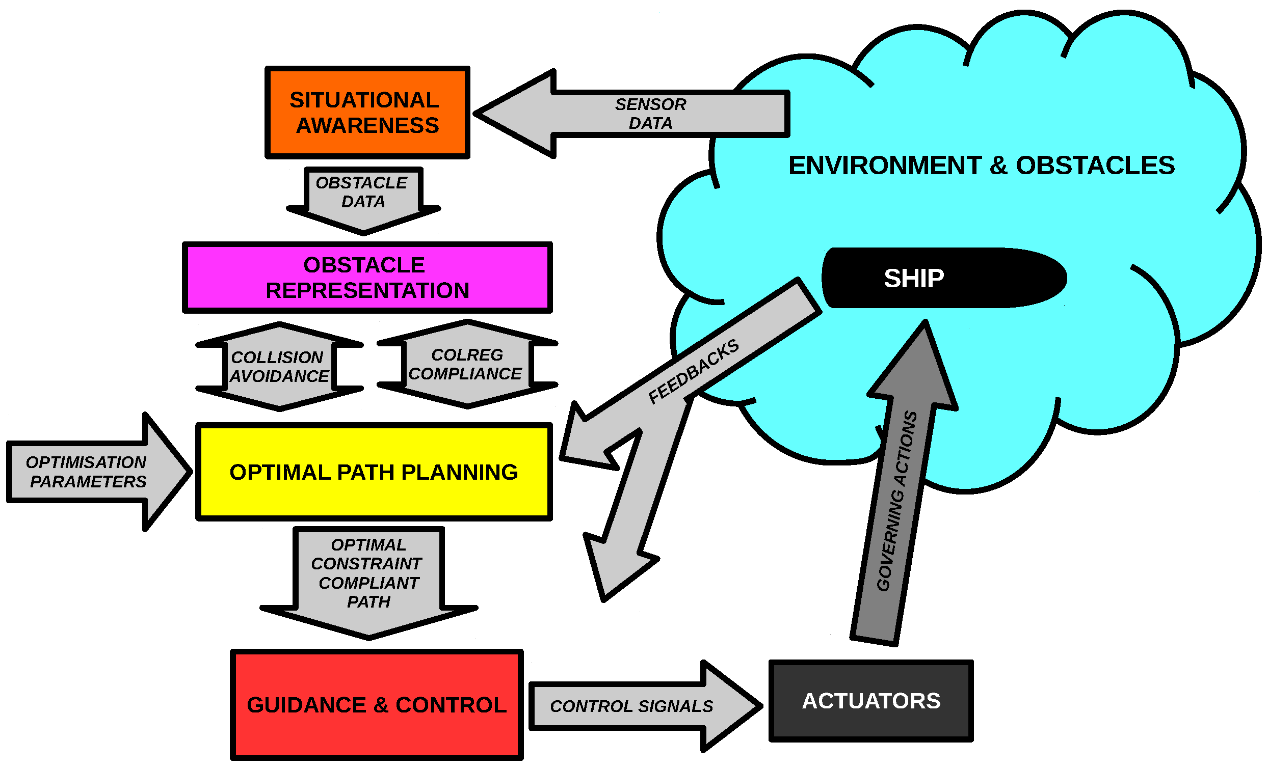
Figure 1 represents the architecture of the MPGC system. During navigation, the situational awareness module collects information about the environment via sensors; the information related to the obstacles, in particular, is organised into a data structure by the obstacle management module and made available to the OPP module. The OPP module is the core of this paper: based on the path optimisation parameters, the position and speed feed-backs from the ship and the information on the fixed and moving obstacles detected in the environment, it computes the optimal, checking collision-free, COLREG-compliant path to reach the arrival point. The path is then processed by the GC system, which computes the appropriate control actions. Eventually, the control actions allow the actuators governing the ship to follow the planned path.
The MPGC system acts at discrete time intervals: with a preset re-planning rate, the obstacle data and the own ship’s position and speed are updated, and the optimal path is recomputed and sent to the GC module. The OPP module predicts the motion of the detected moving obstacles to ensure collision avoidance and COLREG compliance. The periodic re-planning allows updating the obstacle’s data with any unpredictable changes.
The situational awareness module was not the aim of this discussion. Thus, information about the surrounding ships and obstacles was assumed to be available from nautical charts, AISs and on-board sensors such as the radar. The paper discusses the obstacle management and OPP modules, focusing on the path optimality and feasibility and collision avoidance and COLREG compliance constraints. An RRT* algorithm efficiently computes the optimal path relying on fast nearest neighbour search algorithms to manage the obstacles. Eventually, the GC module was not the paper’s primary target; however, it had a crucial role in the presented architecture. Later in the article, the described MPGC system is tested in a simulation framework, including the described OPP module, a GC system and a three-degree-of-freedom ship simulation model.
3. The RRT* Path-Planning Algorithm
This section aims to give an overview of the RRT* algorithm [
14,
15,
16], here used to compute the optimal path in the OPP module. RRT* is an optimised variation of the regular RRT algorithm: while the purpose of the RRT algorithm is to quickly generate feasible, collision-free trajectories, efficiently managing obstacles and forbidden regions, RRT* tries to minimise a cost function in the path-generation process, to provide heuristically optimal trajectories. The RRT and RRT* can be described as random-sampling algorithms, as they randomly sample the spatial domain, growing a tree that links the feasible configurations. While the mentioned references provided a detailed description of the algorithms,
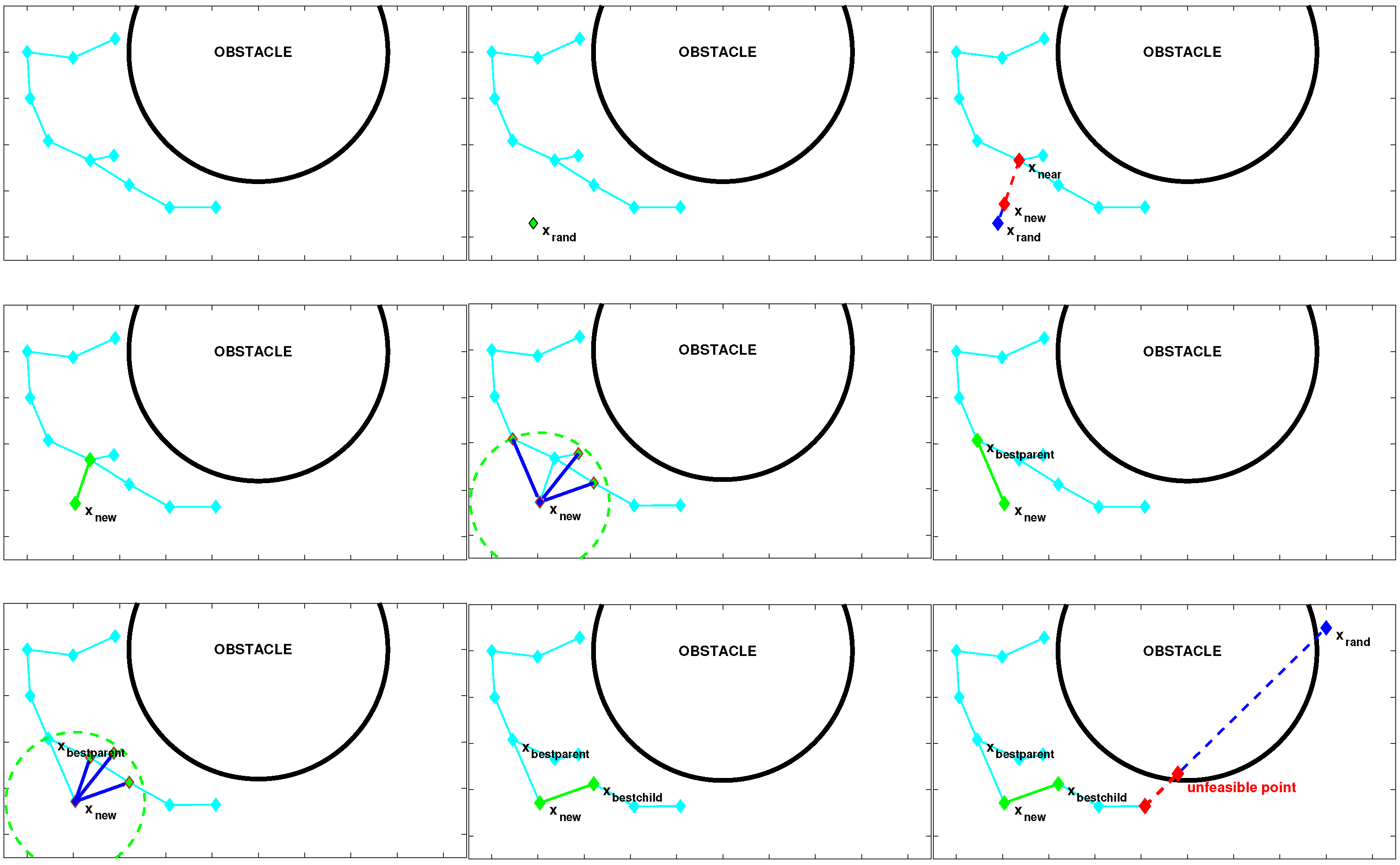
Figure 2 shows a graphical example of the RRT* step, which is described here. A tree
G, composed of a set of nodes
V and a set of edges
E, is grown. At each step, a new node and edge are added according to the following actions:
A random position is generated, then the node that is nearest to is selected;
A new node is generated by moving towards from by a fixed step;
The edge linking and is then checked for collisions; both the node and the edge are then added to the tree.
The standard RRT algorithm is high in speed due to the limited computations; yet, it may generate sub-optimal, very irregular paths. Moreover, increasing the number of iterations does not improve the smoothness of the obtained trajectories. Note that constraints can be checked while generating the new edge, including, for example, a kinematic or dynamic model of the vehicle. The RRT* is an improved, optimality-driven version of the RRT that allows computing heuristically optimal paths according to a cost function. The cost function allows the algorithm to compare alternative path solutions, driving the tree growth towards optimality. After having generated the node , the RRT* adds two additional steps to achieve path optimisation:
A neighbourhood of the new node is searched for the best parent node that minimises the cost function in , in compliance with the constraints.
is considered a possible parent node of each of the neighbour nodes: in case is a better parent than the current node, it becomes the new parent of the neighbour node. This action is usually called rewiring.
As mentioned above, the cost function allows controlling the tree’s shape, i.e., the algorithm’s output trajectories. Moreover, the solution heuristically converges to optimality at each iteration; thus, more iterations lead to better solutions.
4. Optimal Path-Planning Problem Setup
This section discusses in detail the features of the optimal path-planning system. In particular, it defines the path structure; then, it discusses the cost function and constraints of the optimality problem, with a specific focus on the COLREG compliance constraint.
4.1. Path Structure and Turning Angle Constraint
The OPP module aims to plan a trajectory in the form of a set of waypoints, relying on the GC system for the actual path following. As opposed to dynamic model-based motion planning, this approach is a simple way to deal with the ship’s complex, unpredictable dynamic behaviour. It requires only basic kinematic and geometric constraints to model the vessel’s turning capabilities, relying on the control system to manage the model simplifications’ effects. To this end, the planned path is represented by a set
S of waypoints
:
Two waypoints identify one route segment. The steering angle between two segments is related to the ship’s manoeuvring capabilities. Expressing the
pth and the
th segments in the vectorial forms
and
, respectively, the steering angle in
is:
In the proposed OPP system, such an angle is required to be less than a threshold value to be compatible with the vessel’s manoeuvring capabilities.
4.2. Obstacle Management and Collision Avoidance
Two types of obstacles can be identified: fixed and moving. Fixed obstacles include anything that is not moving in the scenario, such as the shoreline or any floating yet not moving body. A set
F of points (vectors) models the fixed obstacles. As the algorithm will repeatedly compute the distance to the closest obstacle, organising the points in an appropriate data structure to make this operation faster can significantly enhance the computation performance. In this work, a kd-tree data structure [
37] was implemented to ensure fast nearest-neighbour search capabilities. Moving obstacles, also referred to as targets, include any vessel moving in the scenario. The targets’ instant positions are denoted
, while the set of all the target positions detected at time
t is indicated by
. Targets can in principle move according to any law of motion: for the purposes of this work, the targets’ positions
and speed vectors
are collected and updated each time
the OPP algorithm is called, at a defined path re-planning rate. Within the re-planning instants, the position of each target is extrapolated by approximating its motion as follows:
When computing the evasive manoeuvre, the distance from the closest moving or fixed obstacle needs to be greater than a threshold value
representing the distance below which the collision hazard is too high:
The safety distance should be defined considering the uncertainties of the obstacle detection system and the possible track errors due to the GC system.
4.3. Cost Function
The definition of the cost function is crucial to control the path shape and features: while the RRT grows, the optimising action of the RRT* algorithm locally reshapes the tree to minimise the desired cost. Three main desirable features have been identified:
In principle, these features can be in conflict, and one or more of them might not be required: the desired result can be obtained as a trade trade-off solution via cost function aggregation, i.e., using a properly tuned weighted summation of different contributions. The general cost formulation at the generic waypoint
can be expressed as follows:
where
represent the summation coefficients,
are the cost contributions and the subscripts
s,
f,
m,
l indicate the steering action, the margin from fixed and moving obstacles and the path elongation, respectively. The cost
associated with the steering action is defined as follows:
The minimisation of such a cost function provides relatively smooth trajectories, with reasonably low path elongation. The minimisation of the control actions’ squared sum is a common practice in many optimal control applications. Using solely this contribution produces reasonable solutions, so it is the suggested approach if there are no other particular trajectory requirements. The cost contributions associated with the obstacles,
and
, aim to model a repulsive effect of the obstacles in analogy with potential field methods, in order to selectively maximise the distance:
Such cost functions allow generating very rounded trajectories, maximising the distance from the obstacles, at the cost of significant path elongation. Very constrained spaces, such as restricted waters, mitigate the elongation effect; otherwise, the use in combination with the path-shortening component is suggested. Eventually, the path-shortening component
allows minimising the path length, as it penalises the path elongation:
This last component generates the shortest possible trajectories, linking straight lines with the narrowest turns allowed and barely respecting the safety distance. The summation weights selection should be made according to the path requirements to get the most appropriate solution for the specific ship, manoeuvring capabilities and mission requirement. Note eventually that all the cost contributions are non-negative: in other words, considering two waypoints and , if then .
5. COLREG Compliance
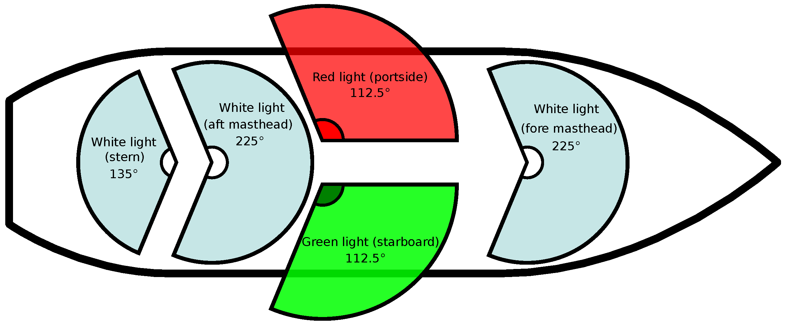
The COLREG regulation aims to provide prescriptions and rules to avoid collisions between vessels. In particular, the regulation targets two main aspects: the vessel’s lights and signals and the correct ship-master’s behaviour when sailing in other ships’ presence. In the steering and sailing rules, the COLREG regulation distinguishes three scenarios: crossing, overtaking and head-on. Referring to the ship navigation lights described in
Figure 3, the required behaviour can be summarised as follows:
In the crossing condition, both ships can see one of the other’s sidelights: in this case, the vessel that sees the other’s red light must give way by turning to starboard, showing its red light (red-to-red).
In the overtaking condition, a vessel reaches another from the aft quarter: in this case, the overtaking vessels must not cross the overtaken vessel’s route.
In the head-on condition, each vessel can see both the other vessel’s sidelights. In this case, the rule prescribes both vessels to turn starboard, resulting in a red-to-red pass.
COLREG was written for human interpretation and based on typical human concepts, referring to ship light colours and relative concepts such as each ship’s port or starboard side. Zaccone et al. [
27] described a mathematical model of the COLREG Steering and Sailing rules for autonomous collision avoidance purposes. Such a model is designed to check if a given scenario is COLREG compliant or not, to be integrated into an OPP algorithm to generate COLREG-compliant trajectories. Note that while COLREG, most of the time, gives both vessels a prescription, the proposed algorithm suggests manoeuvring actions to the own ship only, relatively to the target vessel’s position, heading and speed. Concerning
Figure 4, the algorithm divides the collision scenario into three zones:
The red texture represents a hazardous zone of radius , in which the probability of collision is too high: the purpose of the guidance system is to keep the obstacles out of this region.
The yellow, delimited by a circle of radius , represents the area in which an unexpected action of the own ship or the obstacle vessel may lead to a hazardous situation. In this area, COLREG compliance is required.
Outside the yellow zone, the vessels are considered sufficiently far apart (for example, far enough to be unable to see each other’s lights), so the COLREG check is not required.
In other words, the MPGC system aims to keep the obstacles outside the red zone, respecting COLREG if they are in the yellow area.
5.1. Definitions
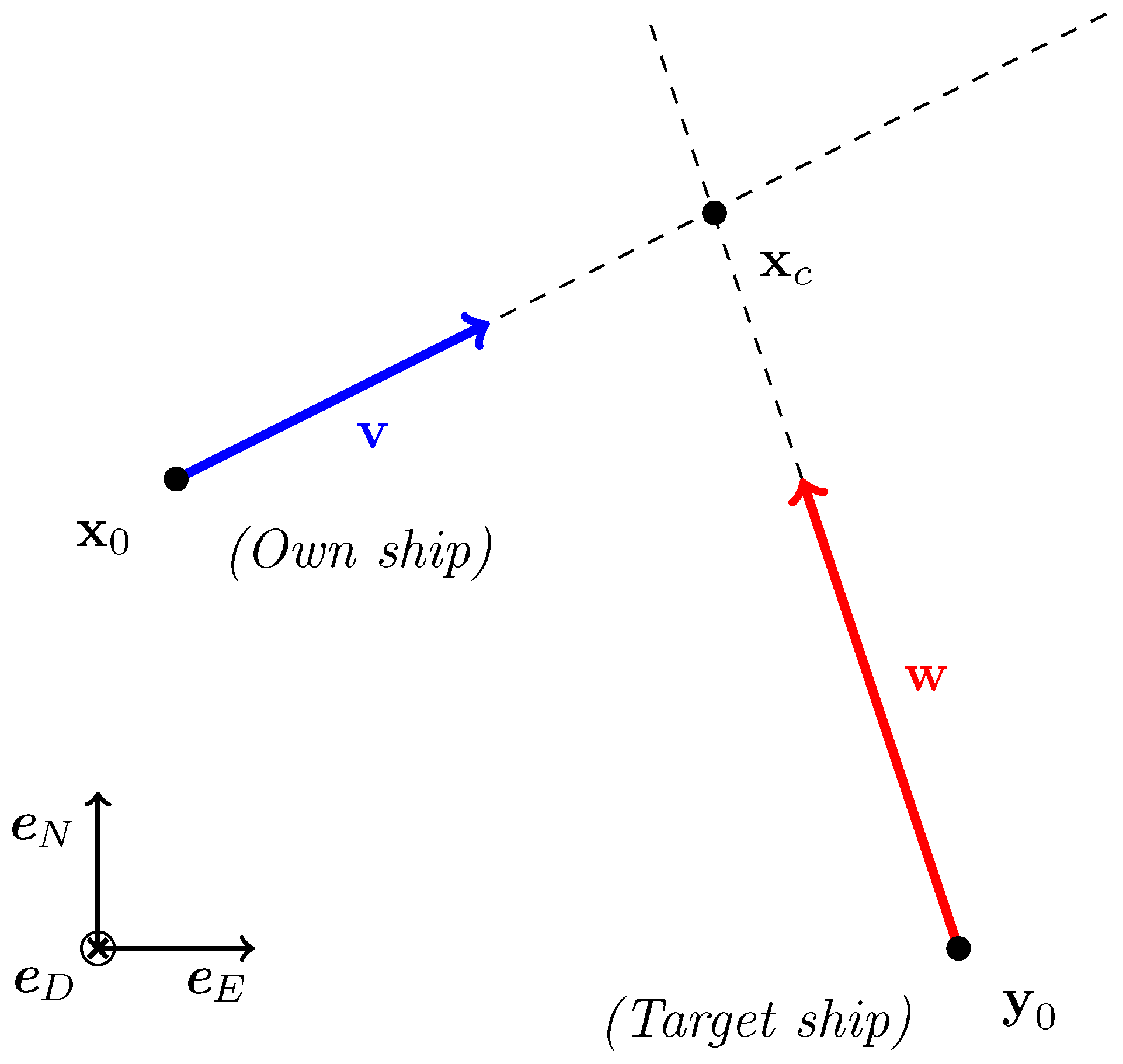
Referring to
Figure 5, a right-hand NED (North-East-Down) system of coordinates
is defined. The own vessel’s position is
, and its speed is
; the target vessel’s position is
, and its speed is
. As mentioned before, the considered scenario needs to match the following conditions:
The distance between the two vessels must be greater than a threshold safety distance during all the manoeuvre.
The initial distance between the vessels must be less than a convenient threshold , otherwise no COLREG check is performed.
The above-mentioned conditions can be written as follows:
where
represents the distance between two points and
y(t) and
x(t) are the target ship’s and the own ship’s instant positions, respectively.
5.2. Intersection Condition
If
and
are two vectors, perpendicular to
and
, respectively, a crossing condition can happen if the following linear system has exactly one solution:
where
indicates a generic point. The condition can thus be written as follows:
In order to avoid the strong equality for numeric purposes, the following equivalent crossing condition is preferred:
where
is a convenient tolerance threshold. The solution of the linear system (
11) is the intersection point
between the own ship’s and the target’s directions (
Figure 5). There is a crossing scenario if
is located both in front of the own ship and the target, and the following inequalities are verified:
Moreover, it is possible to determine which vessel is engaging the point
first, comparing the times of arrival:
Note that in this case, equality means that there is a perfect collision.
5.3. Overtaking
According to COLREG, there is an overtaking scenario if the own ship is engaging the target ship from an angle
of less than
from the own ship’s aft:
If the inequality (
16) is verified, COLREG requires the overtaking vessel not to cross the overtaken one’s route. More in detail, if the two vessels’ routes cross (Inequalities (
13) and (
14) are verified), the scenario is compliant if the target vessel engages the interception point first, in accordance with Equation (
15).
5.4. Crossing
A crossing scenario satisfies Equations (
13) and (
14), while not satisfying (
16): according to COLREG, in this case, the relative orientation between the ships approaching the intersection point needs to be described, by discussing the cross-product between
and
, (positive downwards):
where the equality is excluded by Equation (
13).
The combination of Equations (
17) and (
15) gives the following COLREG-compliant condition for a crossing scenario:
5.5. Head-On
In the head-on condition, COLREG prescribes a turn to starboard for both vessels. As the described algorithm plans the own vessel’s manoeuvres only, if the angle between the vessel’s routes is greater than a head-on threshold angle
, the target vessel must be found on the own ship’s port-side:
If Inequality (
19) is verified, the algorithm must check the crossing condition as well. Unlike in the case of the overtaking angle
, COLREG does not give an exact value of the head-on angle
. For this work, a value of
from the own ship’s fore is assumed as reasonable.
6. Simulation Virtual Test Bed
The OPP algorithm described in the previous sections was implemented: as mentioned above, the RRT* algorithm computes the optimal path, and a kd-tree structure manages obstacles efficiently. The C programming language and gcc compiler were used to maximise the computation speed. It is worth mentioning that all the source code was custom developed and optimised, using only C standard libraries, to keep complete control of the planning process.
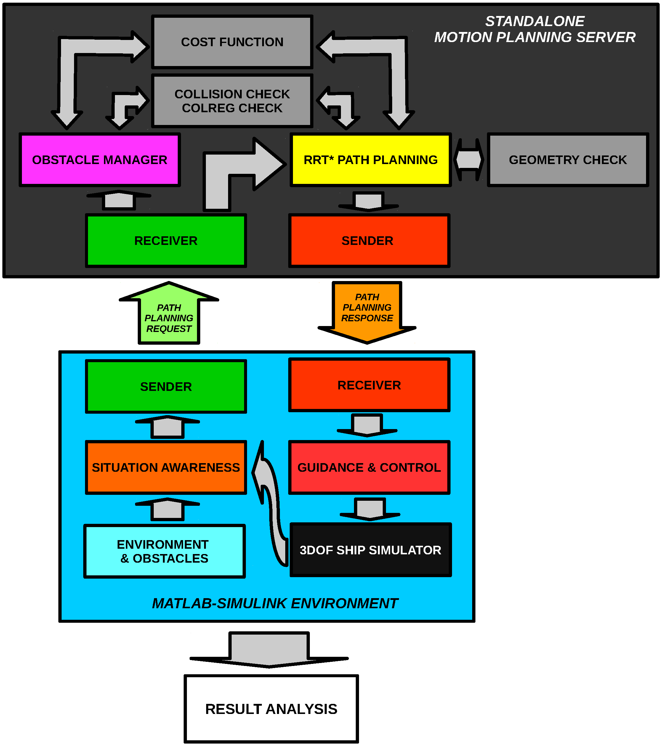
The OPP module was tested in a simulation setup, customised to match the testing requirements. The ship 3DOF simulation model was implemented in a MATLAB-Simulink environment coupled with an advanced GC system that allowed high-performance trajectory tracking and speed control. The OPP module was decoupled from the simulation to make the simulation more realistic. In other words, while the OPP algorithm is computing a new trajectory, the controlled ship is moving and following the old path. This feature was achieved by adopting the client-server architecture shown in
Figure 6: the OPP algorithm was integrated into a standalone server, which plans the trajectory on request, after having received the required information, and sends it back to the client. The implemented OPP module was either set to include or neglect the COLREG compliance constraint. When COLREG compliance is required, the algorithm tries to find a compliant solution. If no path is found, the planning is repeated, relaxing the COLREG compliance constraint. On the simulator side, a path-planning client sends the path re-planning request at a fixed rate, waits for the response and updates the GC trajectory once it has been received. The request message contains the following information:
Own ship’s starting coordinates and heading;
Coordinates and heading of the arrival point;
Own ship’s speed;
Number of detected targets;
Targets’ detected position, speed and heading.
The response message contains the waypoints that allow the own ship to reach the required arrival point safely. The arrival point is reached within a range of the desired heading, allowing a possible integration of the proposed architecture in a higher level offline long-range route planning, with very far apart waypoints. For example, a weather routing system layer [
12,
13] could be implemented on top of the proposed MPGC system. For this research, UDP (User Datagram Protocol) allows the client-server communication. Note that, from the software point of view, the OPP module, the GC and simulation are entirely uncoupled. Moreover, the communicating modules can be run either on the same computer or on different machines on the same network. Moreover, the same architecture applies to a “real” ASV (Autonomous Surface Vessel) for experimental testing, as long as the connection is ensured.
The simulation model used in this work was a multi-domain platform, modelling the dynamics of a vessel in three degrees of freedom, taking into account the complete propulsion system with automation effects. The simulator integrates differential and algebraic equations and response surfaces to represent ship propulsion, manoeuvrability and control systems. Detailed information about the simulation platform was discussed by Alessandri et al. [
35], while the validation of the simulator using sea trial data was published by Donnarumma et al. [
38]. The simulation platform included a virtual reality interface [
36], with the main focus on developing decision support systems for collision avoidance purposes [
23,
26], as well as guidance and control algorithms. In particular, the GC module integrated into the simulator was described in detail by Alessandri et al. [
33], Donnarumma et al. [
34].
7. Results and Discussion
The described MPGC system was tested in a simulated scenario, including the own ship and two other target ships. The extension of the test case map was ship lengths (). The ship’s mission consisted of sailing through the map from one corner to the opposite while keeping a safe distance of 10 ship lengths from both targets and respecting the COLREG constraint. The starting point was located in , and the goal point was . The collision avoidance algorithm was set up to keep the distance between the ship and the obstacles larger than 10 ship lengths while minimising a convenient balance between the proposed cost functions: the coefficients were selected via trial and error. Three scenarios were set up to be challenging for the OPP algorithm.
- (1)
The first scenario included two targets in open-water navigation: the first target came from the starboard side, the second from the port side;
- (2)
The second scenario featured a first target coming from ahead and another one coming from the starboard side, in open-water navigation;
- (3)
The third scenario featured a head-on condition with a target ship coming from ahead in a narrow canal.
Table 1 shows the target data in the considered scenarios in the NED coordinate system. The system was tested in the simulation in realistic conditions to evaluate the proposed approach’s guidance capabilities. Firstly, the simulation was performed in real time, and noise was artificially added to the obstacle data to replicate actual sensors. A re-planning rate of 15 s was considered. On average, the time required for the re-planning was about
s. The simulation framework was set up on a standard commercial notebook.
It should be pointed out that, in the considered scenarios, the COLREG-compliant and non-compliant trajectories were significantly different. The result obtained considering and neglecting the COLREG constraint will be compared and discussed in the following section. Moreover, for each case, the targets’ unexpected behaviour was simulated to stress the algorithm and test the MPGC system’s reactive capabilities.
7.1. Scenario 1
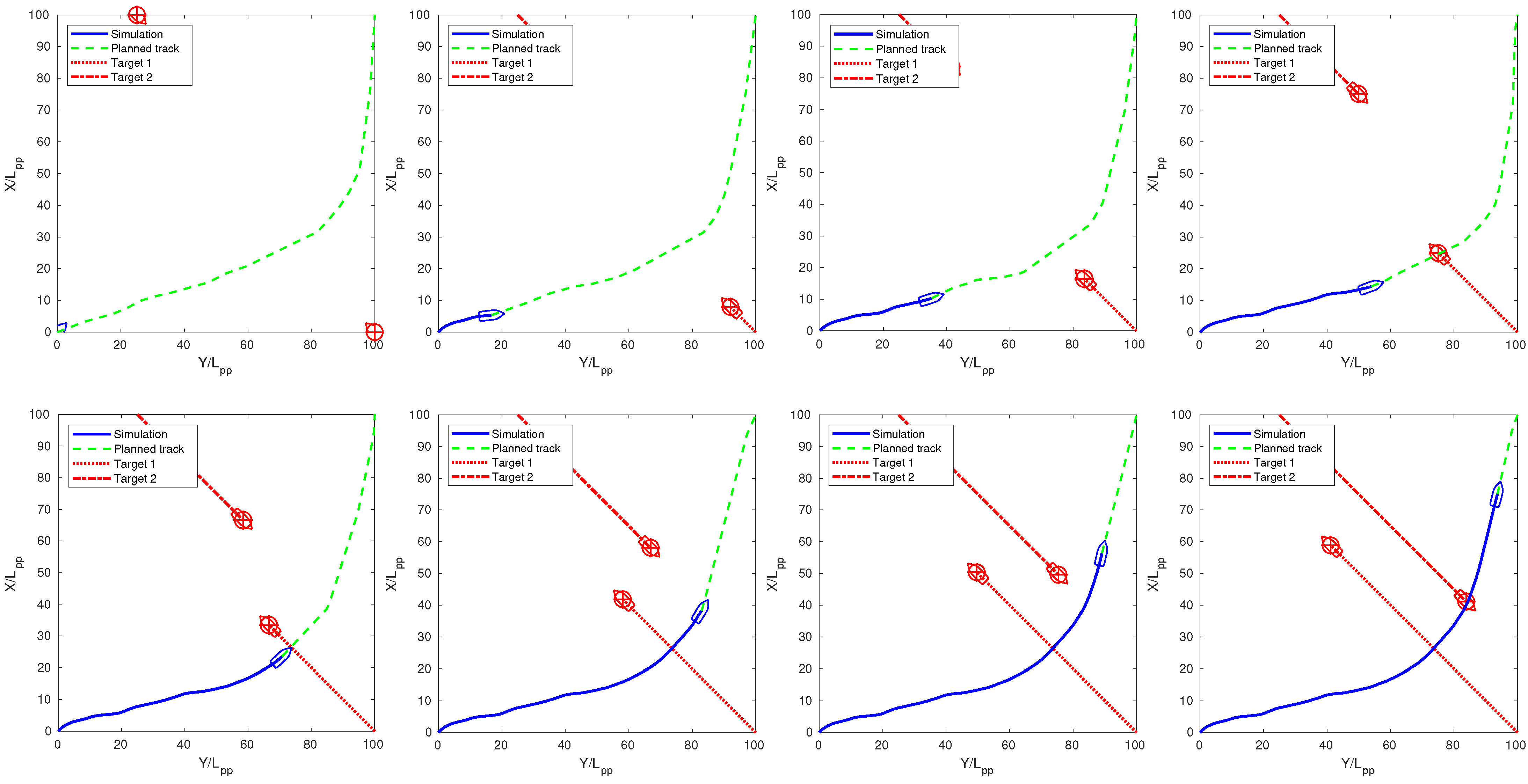
The first scenario featured two moving targets, respectively starting at
and
and sailing along routes
and
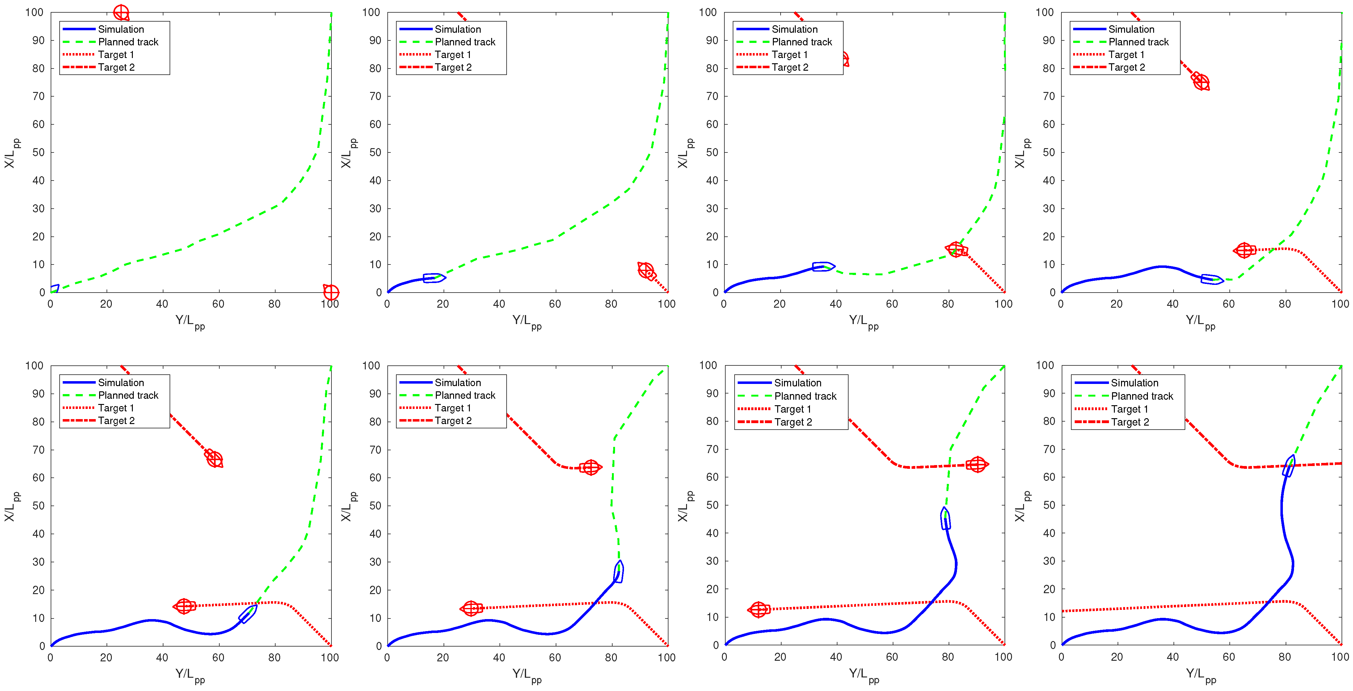
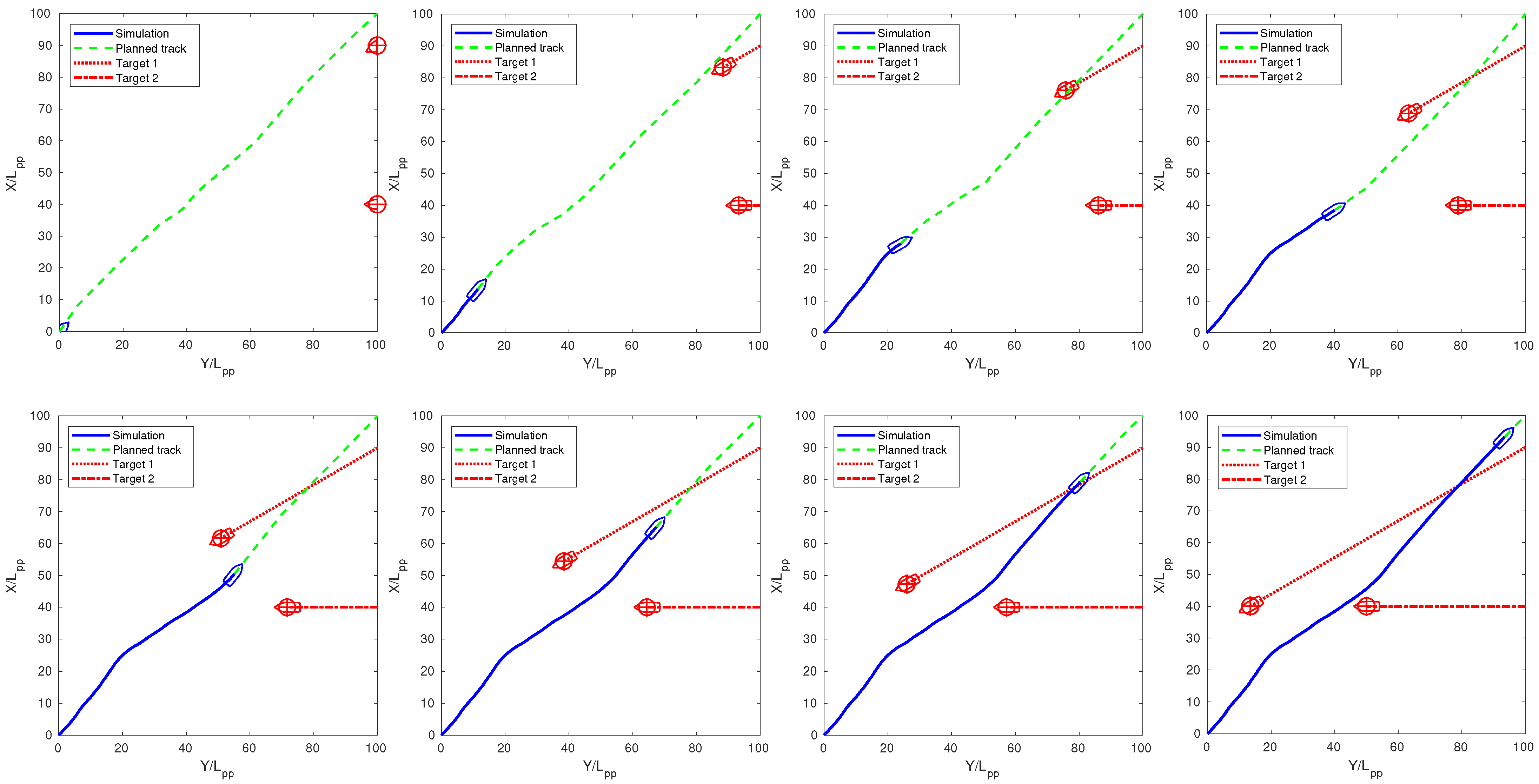
, respectively. The simulation results with and without the COLREG compliance requirement are shown in
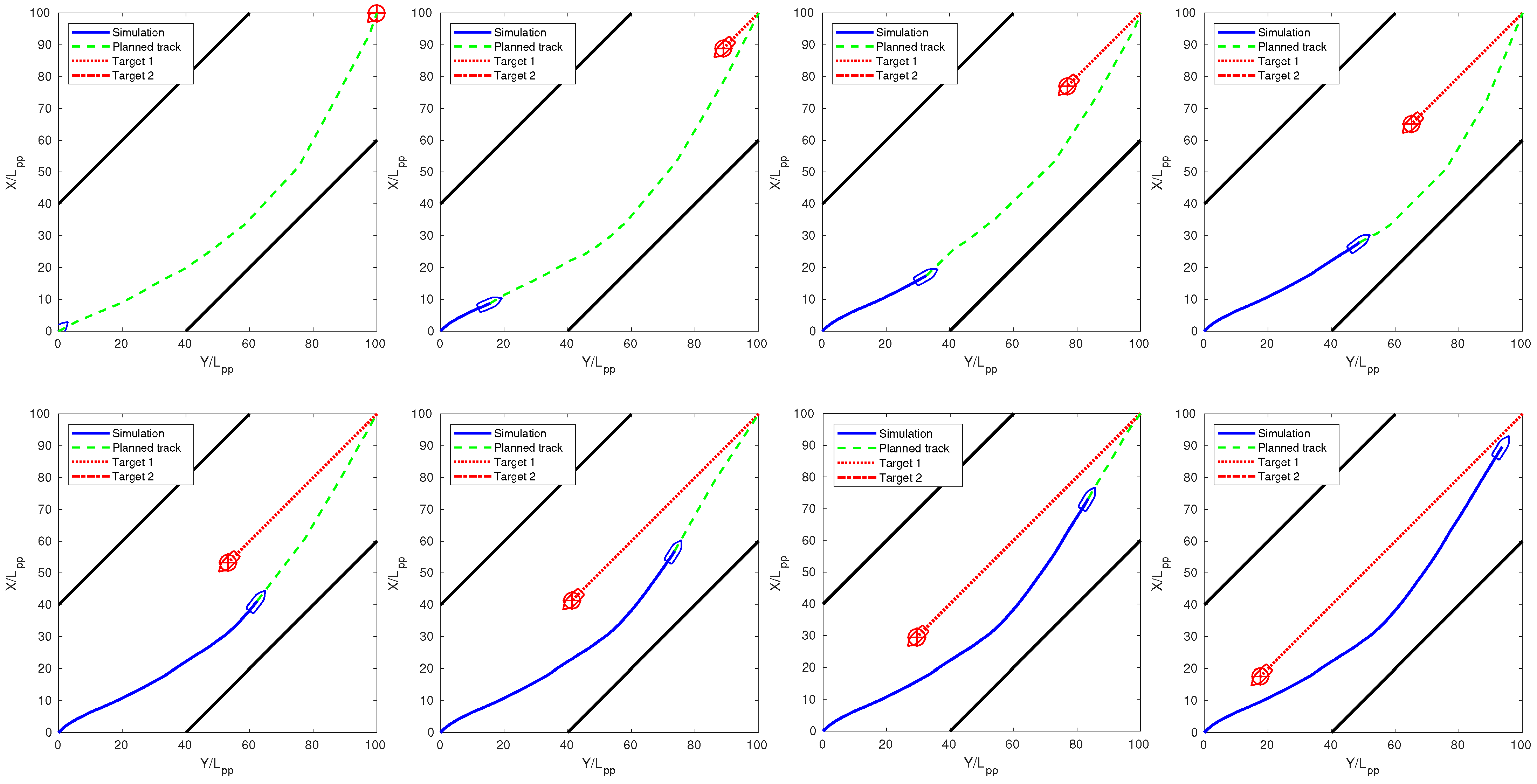
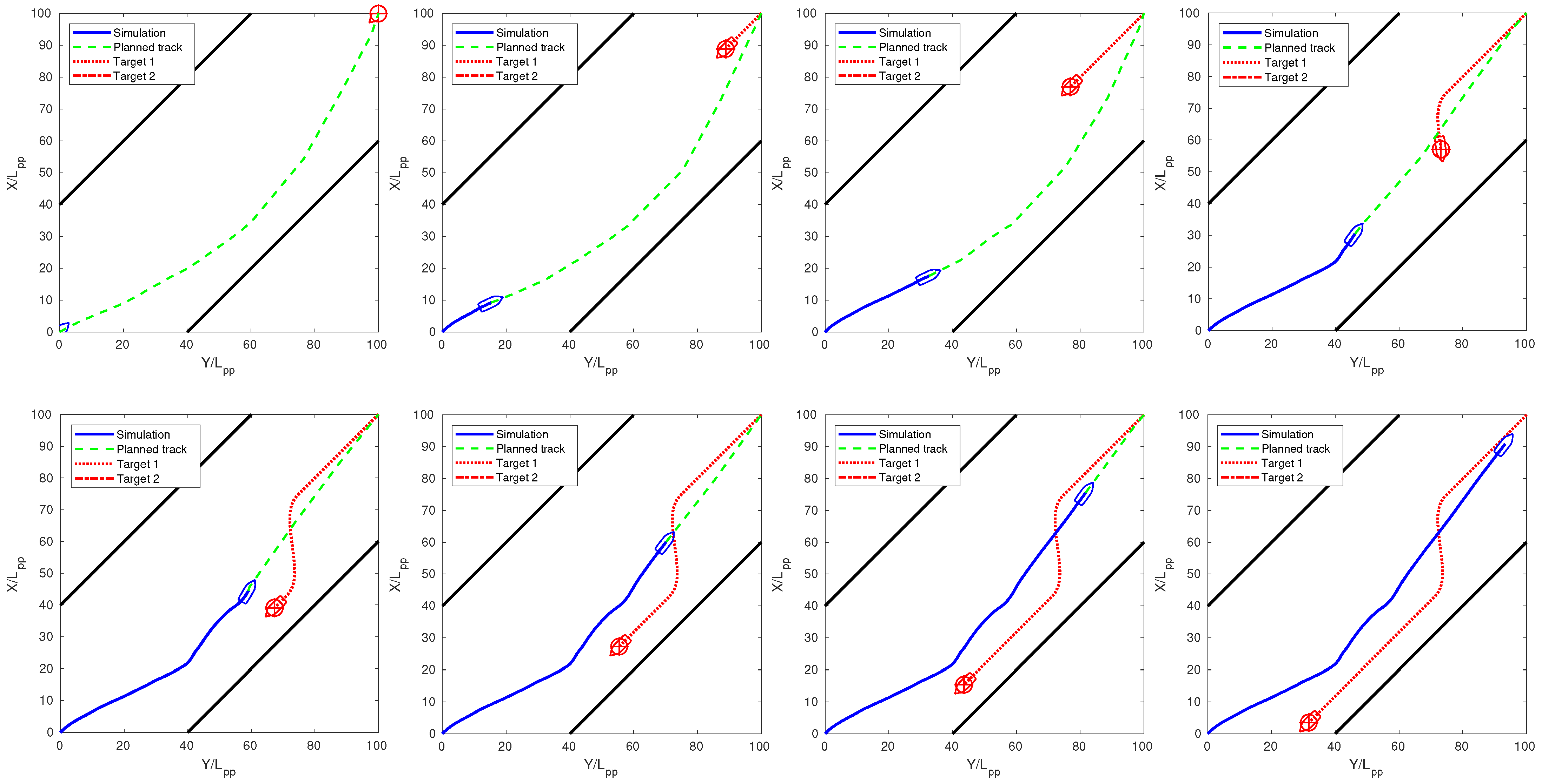
Figure 7 and
Figure 8, respectively. Note how different the solutions were: if COLREG was required, the own ship was forced to give way to the first target, coming from the starboard side, while the COLREG non-compliant solution allowed maintaining more distance from the obstacles.
Figure 9 presents a conveniently modified version of the scenario, featuring an unexpected change in the targets’ course that forces the OPP algorithm to alter the intended ship’s path significantly. Note how the own ship suddenly steers to its starboard side to avoid the unexpected and inconvenient target’s steering and is forced to steer again to port to avoid the second obstacle, changing from a COLREG-compliant stand-on behaviour to a non-compliant give-way.
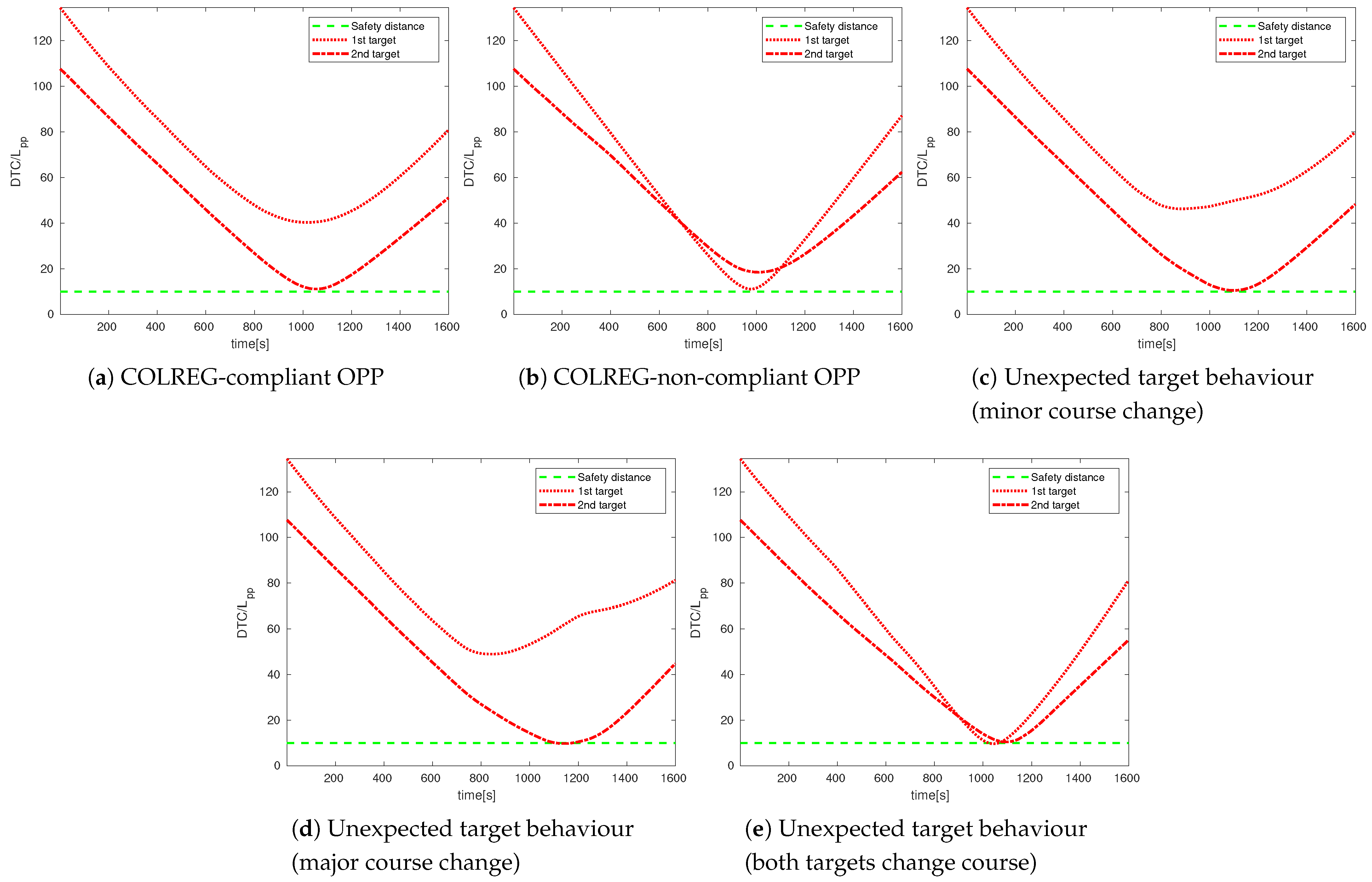
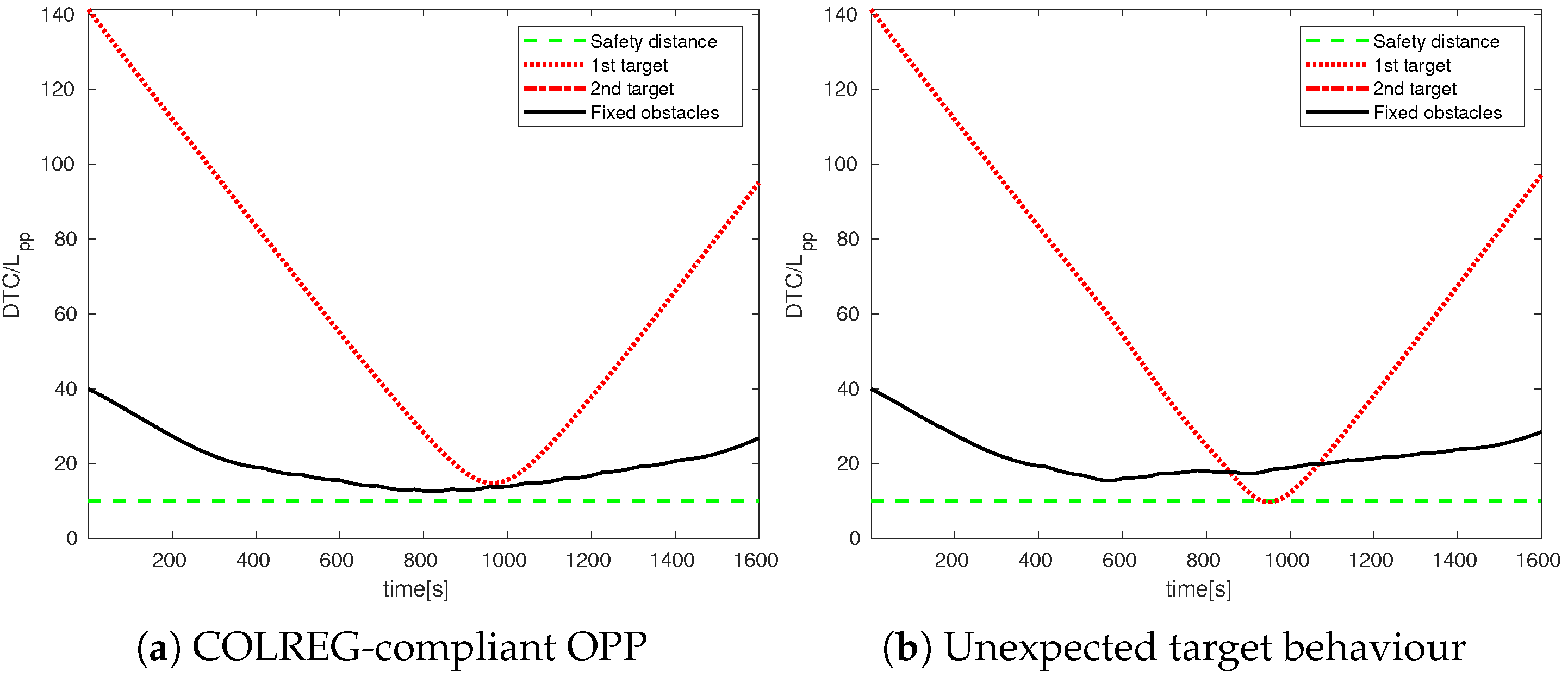
Figure 10a–c shows the DTC (Distance-To-Collision) from the targets during the simulated manoeuvres. Note that the simulated paths always respected the safety distance.
7.2. Scenario 2
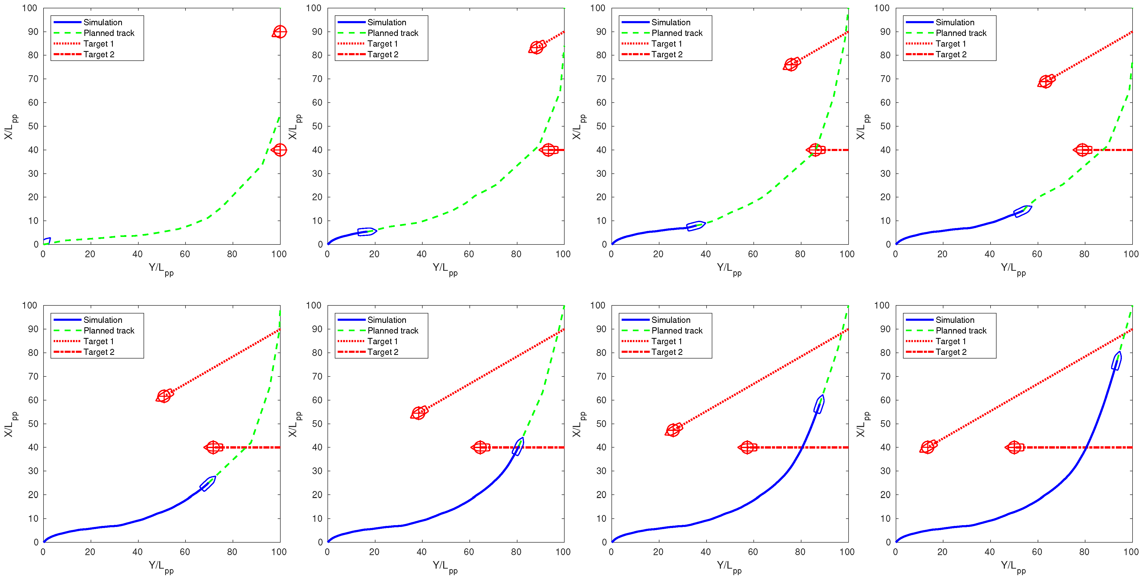
In the second scenario, the two moving targets started at
and
, along routes
and
, respectively. The simulation results are again presented, including and excluding the COLREG compliance requirement.
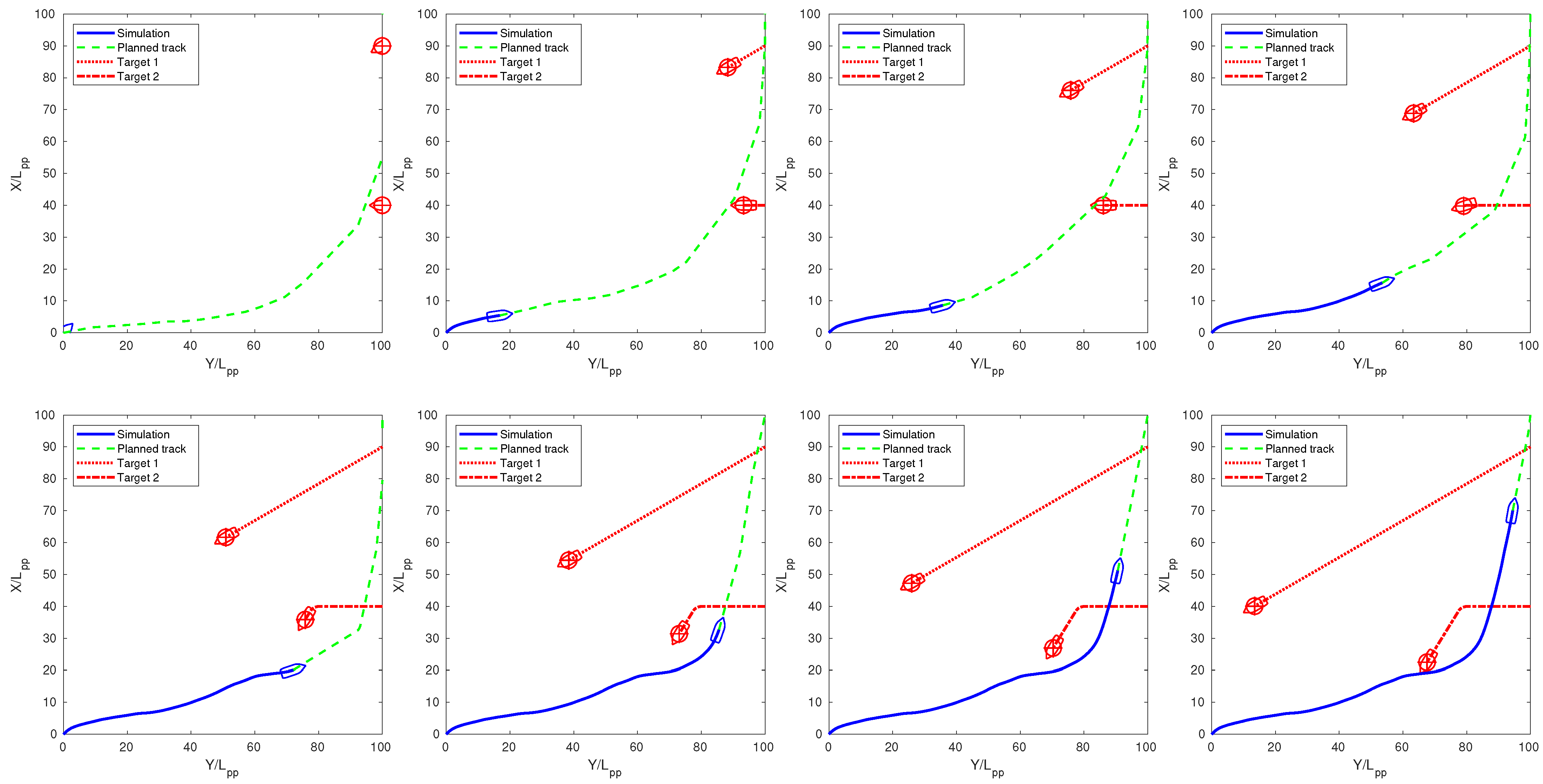
Figure 11 and
Figure 12 show the results: note that, in this second case, the non-compliant solution was quite close to the targets, as the OPP algorithm found a direct, yet hazardous solution, which was indeed not COLREG compliant because it did not give way to the obstacle coming from the starboard side. The scenarios presented in
Figure 13 and
Figure 14 include, once again, an unexpected variation of the second target’s course towards the own ship that forced the OPP algorithm to react to avoid a collision. In particular, a minor and a major course change were considered, respectively. Eventually,
Figure 15 shows a further scenario variation where both the targets were close to the own ship and behaved unexpectedly. Repetitive path updates allowed the own ship to avoid the collision finally.
Figure 16 shows the DTC from the targets during the simulated manoeuvres. The safety distance was respected in both COLREG-compliant and non-compliant manoeuvres in the absence of targets’ unexpected behaviour, as shown in
Figure 16a,b. Moreover, the simulated trajectory respected the safety distance in the presence of a minor unexpected target’s course change. In contrast, a major change made the own ship violate the safety distance by a small amount, as
Figure 16c and
Figure 16d show. This slight violation was considered acceptable: the scenario was built with the explicit purpose of stressing the MPGC system’s reactive path-planning features, and the target’s steering was very unlikely in a real navigation scenario. Moreover, the safety distance should consider possible slight violations due to measurement errors and delays due to control and actuation systems. Eventually, the own ship was able to respect the safety distance in the last simulation, as shown in
Figure 16e.
7.3. Scenario 3
As opposed to the first two, the third scenario featured restricted waters, featuring both fixed obstacles (the canal walls) and one moving target. In particular, there was only one moving target, starting at
with a heading of
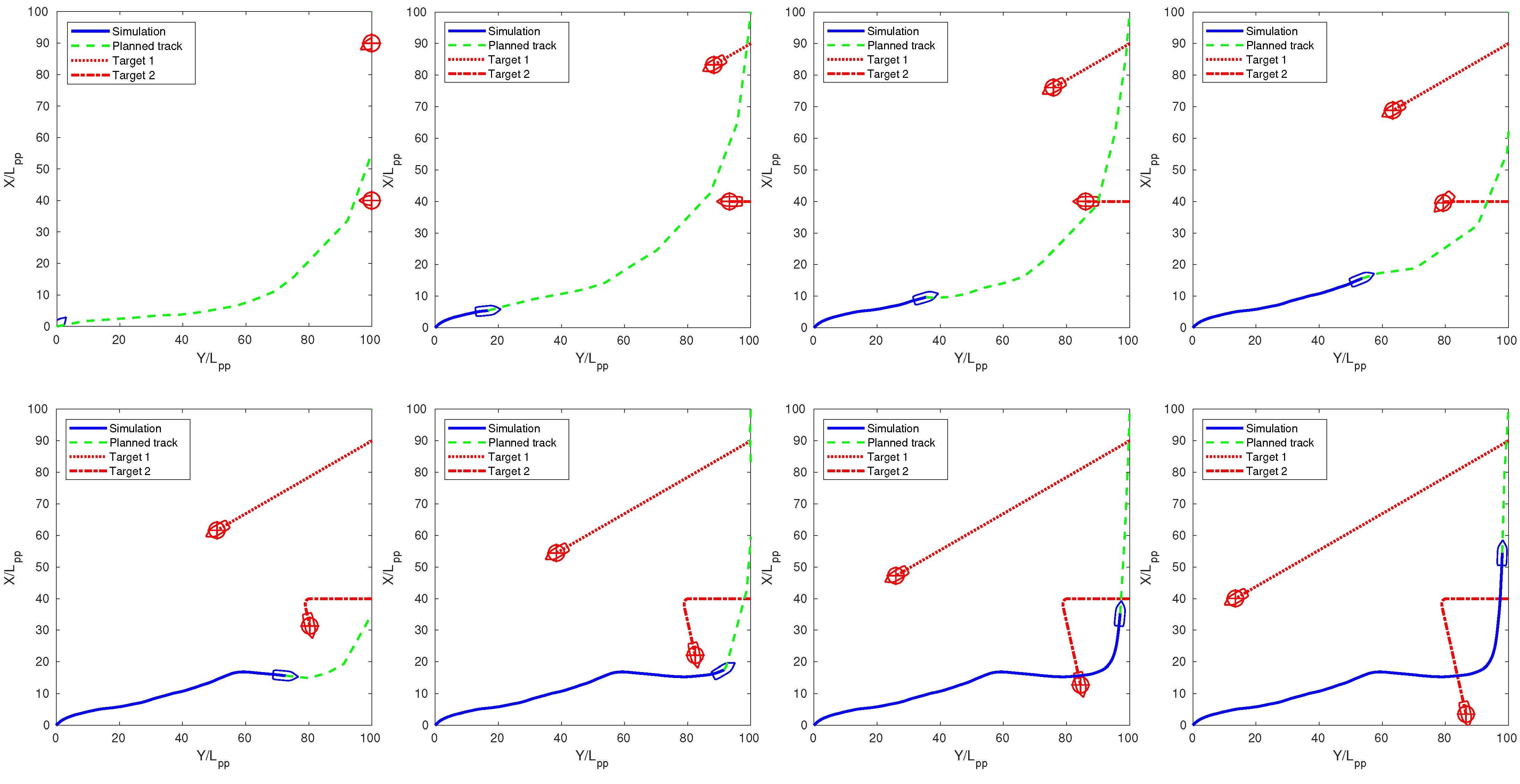
. Both the target and the own ship were sailing into a narrow canal in opposite directions. Note that the scenario was perfectly symmetrical; thus, neglecting COLREG compliance did not bring any significant advantage: the solutions might differ or not because the non-compliant RRT can randomly choose to steer to either side to avoid the collision. The simulation presented in
Figure 17 was obtained using the COLREG-compliant algorithm, while the non-compliant path planning provided similar results. The third scenario was modified to stress the OPP module’s re-planning capability by including an unexpected manoeuvre made by the target. The target’s new route did not allow a COLREG-compliant path, and the OPP was forced to switch to non-compliant mode. The simulation results presented in
Figure 18 highlight this behaviour. The DTC in
Figure 19a,b also includes the distance from the fixed obstacles. Note that in
Figure 16b, the path barely respected the safety distance because of the target’s sudden route changes.
8. Conclusions
In this paper, an optimal path-planning system for ships’ autonomous navigation, based on the RRT* algorithm, was discussed in detail, focusing on collision avoidance and COLREG compliance. A motion-planning, guidance and control architecture was proposed, integrating the OPP with a guidance and control module. The proposed MPGC architecture was implemented in a virtual simulation testbed to be tested in realistic scenarios. The MPGC system autonomously controlled a ship simulation model in real time in three realistic scenarios. The simulation featured both open and restricted navigation, multiple moving targets and fixed obstacles and simulated noisy sensors and moving targets changing their trajectory unexpectedly to put the OPP to the test. Simulations were performed both considering and neglecting the COLREG compliance constraint for comparison purposes.
The simulation results highlighted the described approach’s potential: thanks to the limited time required by the OPP, the periodic re-planning showed good planning and reactive planning capabilities. The simulated trajectories respected the safety distances in most of the cases. In some of the simulations, unexpected targets’ trajectory changes, deliberately designed to put a strain on the MPGC system, resulted in a safety distance violation by a small and acceptable amount. The MPGC system managed to keep control of the own ship and conclude the manoeuvre, switching from COLREG compliance to non-compliance when necessary. To summarise, the proposed architecture showed good potential for autonomous navigation applications.
However, many aspects need further investigation. On the simulation side, the MPGC system, which can be seen as a medium-range or short-range collision avoidance system, should be integrated with a higher level, offline route planning system, managing the long-range routing. Moreover, the weather’s effects should be included in the simulation. Furthermore, the OPP system should be improved to provide optimal manoeuvres considering the current weather conditions. On the experimental side, a model-scale testbed will be implemented to perform tests on an autonomous ship model, including real hardware and actual sensor data.
