1. Introduction
International transport is a common part of the world global transport system. Several important transport corridors pass through the territory of Ukraine, among which the Baltic-Black Sea direction and the International Transport Corridor, which allow the transport of container cargo from Asian countries to European ones, should be noted. The development of foreign economic relations between Eurasian countries contributes to the creation of combined transport systems.
The increase in the transportation of liquid cargo during combined transportations through the territory of Ukraine and abroad has made it necessary to create and implement the innovative vehicles of a new generation. Tank containers are one of the well-known and currently most promising transport modes.
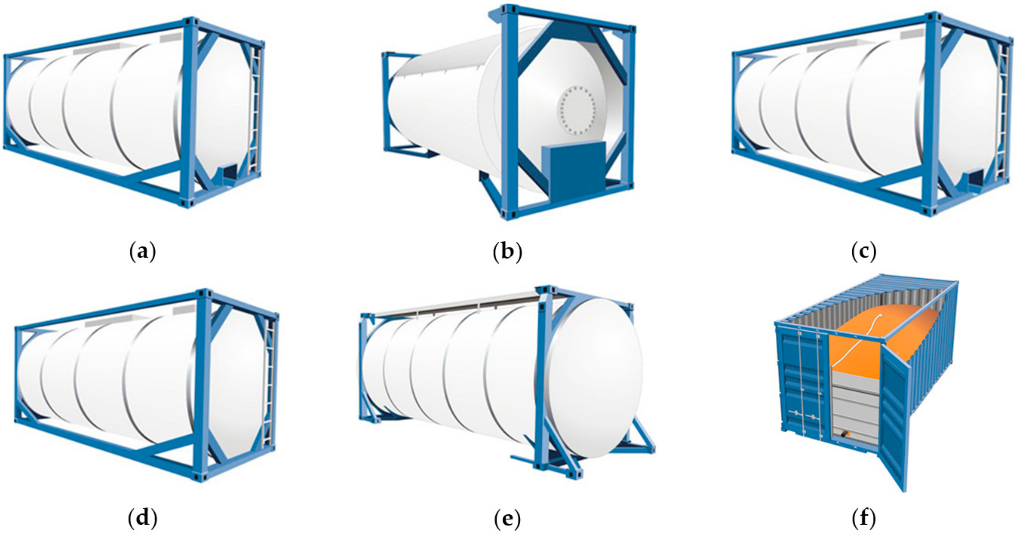
A tank container is a transport unit, namely, a metal tank, embedded in a steel frame, the size of which corresponds to the size of a conventional container for the transportation of dry goods and is intended for the carriage of liquid chemical and food products, as well as liquefied gases, by three types of transport: sea (river), rail and road. The classification of tank containers is shown in
Figure 1.
Transportation in tank containers is carried out without intermediate overflow of the product when changing the mode of transport; it ensures increased safety of transportation and safety of cargo and also improves the environmental factor during transportation.
The use of tank containers allows the optimization of logistics operations for the transportation of liquid chemical and food cargo, as well as liquefied gases, due to the lower cost of the railway costs as compared to transportation in tank wagons. The main advantage is the ability to quickly tranship tank containers from one type of transport to another, excluding the reloading of products at the liquid bulk terminals.
The main global manufacturers of chemical and food tank containers include: CIMC (Shenzhen, China), Van Hool (Koningshooikt, Belgium), Welfit Oddy (Port Elizabet, South Africa), Uralkhimmash (Ekaterinburg, Russia), Uralkriomash (Nizhny Tagil, Russia), etc. Mostly, tank containers are made in China. The world leader CIMC produces almost 60% of the total world production [
1].
The commissioning of an international transport corridor from Ukraine to China and vice versa from China to European countries predetermines the need to study the dynamic load of tank containers during transportation by rail and on rail ferries as part of a combined transport system.
The issue of tank containers’ transportation by sea requires special attention, since the presence of a free surface causes an additional load on the supporting structure of the tank container and, accordingly, affects its resistance to the platform wagon frame. It is important to note that the dynamic processes accompanying the railway rolling stock, including containers (tank containers) when transported by sea, differ significantly from the operating conditions on main lines. This can facilitate the transfer of containers (tank containers) relative to the placement on the platform wagon and requires additional study. In addition, the presence of a free surface of the bulk cargo in the barrel of the tank container contributes to an additional dynamic load on it and deteriorates its stability during transportation by sea.
In consideration of the studies analysis and by examining a significant number of works, it became known that the results of the optimization of the supporting structure of the tank container are given in [
2]. This work proved the feasibility of the engineering design and launching into operation tank containers as vehicles. An improved design of a tank container for the transportation of light oil products has been developed. It is important to note that the loads that can act on the tank container when transported by rail ferry were not considered.
Requirements for the supporting structures of modern vehicles are presented in [
3]. These requirements are proposed to be applied at the stage of manufacturing new constructions of vehicles, as well as those subject to renovation. However, at the same time, no attention is paid to the study of the dynamic load of tank containers during transportation on rail ferries.
Requirements for improving the stability of rolling stock under operating load conditions are set out in [
4]. The results of mathematical modelling are confirmed by experimental studies.
The determination of the dynamic load of vehicles is carried out in [
5]. As the investigated parameter, accelerations were considered as components of the dynamic load. The calculations were carried out by means of mathematical modelling. At the same time, the determination of the stability of tank containers under operating loading conditions in these works was not carried out.
The determination of the dynamic load of containers under operating conditions is carried out in [
6]. The presented mathematical models are validated by computer simulation and verification for adequacy. At the same time, studies of the dynamic loading of tank containers during transportation on a rail ferry are not given.
Studies of the dynamic load of vehicles during transportation by rail ferry are carried out in [
7,
8]. The results of mathematical modelling are confirmed by computer simulation. However, at the same time, the case of a tank container dynamic load during transportation as part of a combined train on a rail ferry was not taken into account. Simulation of the dynamic load of vehicles during operation on main lines is carried out in [
9]. The determination of the dynamic load of tank containers as part of mixed trains during transportation on rail ferries was not studied in these works.
Simulation of the longitudinal load of a tank container placed on a long-base structure of a flat car is carried out in [
10]. The numerical values of the accelerations acting on the tank container are given considering the possible displacements of the fittings relative to the fitting stops. The study of the dynamic load of a tank container during transportation on a rail ferry is not given attention to in this work.
In the papers [
11,
12], the main ways of increasing the degree of ideality of freight wagons and the development of the running gear of the new generation cars, taking into account the dynamic loads that affect these wagons and their running gears during operation, are determined. In the papers [
13,
14], the results of dynamic load simulation of containers and the study of their stability, placed on flat cars during railway ferry transportation, are presented. In the cited works, however, no attention is paid to the studies to determine the dynamic load and strength of tank containers that are placed on a flat wagon while trains are being loaded onto a railway ferry.
The research [
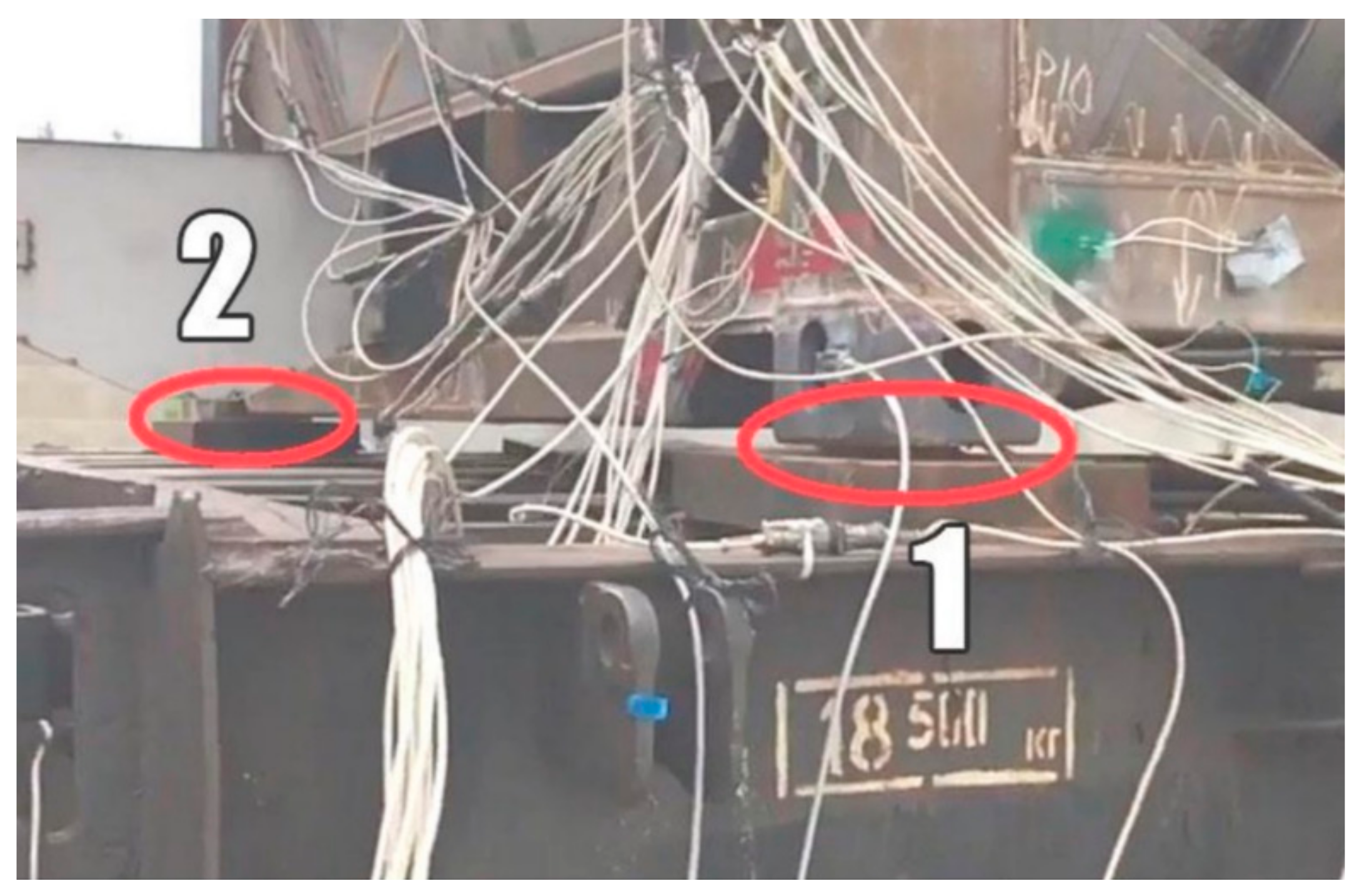
15] performed on testing tank containers shows that during impact tests, due to a combination of design features of fitting stops and longitudinal loads of large magnitude, their wear occurs. The lack of rigid fastening of the container to the platform, the presence of a gap between the fitting of the tank container and the fitting stop on the car, as well as the wear and tear in the operation of the fitting stops themselves, lead to the fact that the container car does not always perceive the shock load upon impact. That is, the impact load is not transmitted to all four fittings in the same way, as simulated in the calculation process. There is significant bouncing of the container immediately after the impact. In this case, not only diagonal fittings or fittings on one side of the container can bounce, but also fittings from the impact side, as shown in
Figure 2.
According to
Figure 2, at the time of impact of the tank container, the fittings from the striking side are lifted above the platform of the fitting stop, while the entire load is transferred to the distant fittings.
Such a feature requires the use of a sufficiently large number of experiments (impacts) to obtain reliable research results; moreover, for a typical collision scheme (see
Figure 2), it is almost impossible to obtain vibration frequencies less than 50 Hz.
Thus, according to the results of the literature source analysis [
2,
3,
4,
5,
6,
7,
8,
9,
10,
11,
12,
13,
14,
15,
16,
17,
18,
19], it can be concluded that the issues of determining the dynamic load of tank containers during transportation on a rail ferry have not been fully studied so far. At the same time, the determination of the dynamic load of tank containers as part of mixed trains with tank cars during the formation of a traction connection before loading onto a railway ferry and during shunting operations (roll on/roll off) on the lower and upper decks of a railway ferry was not investigated in these works, though it is one of the main stages of the tank container testing. This raises the need for appropriate research, which will contribute to improving the efficiency of the operation of tank containers and the safety of transportation by combined transport.
In this work, it is proposed to pay special attention to the features of testing the strength properties and the study of the dynamic load of tank containers placed on a flat car under the influence of longitudinal loads, which simulate impacts during the formation of trains on shunting humps before loading them onto a railway ferry.
2. Computational Model
The testing of portable tanks and multiple element gas containers (hereinafter: MEGCs) to confirm the ability to withstand the longitudinal impact should be carried out on a specially equipped test bench or with a flat rail car by impact with a platform with a tank container placed on it. To ensure the strength of the tank-containers in service, there are a number of regulatory documents that regulate the basic requirements for their design and operating conditions: “International Code of the Carriage of Dangerous Goods by Sea (IMDG Code)” [
13], “Register of Shipping of Ukraine. General regulation on the technical supervision of containers” [
14], GOST 31232 “Containers for the transport of dangerous goods. Requirements for operational safety” [
15], DSTU 7598 “Freight wagons. General requirements for the calculation and design of new and modernized 1520 mm gauge cars (non-self-propelled)” [
16].
The delivery of liquid cargo in tank containers for export from manufacturing plants to the seaport is carried out by automobiles or railway tank cars. Concerning the cost of transportation, this type of transportation of liquid cargo is the most efficient and cost effective. The choice of the vehicle type depends on the amount of liquid cargo that needs to be transported, the territorial location of the manufacturer, and the transport interchange of the product supplier.
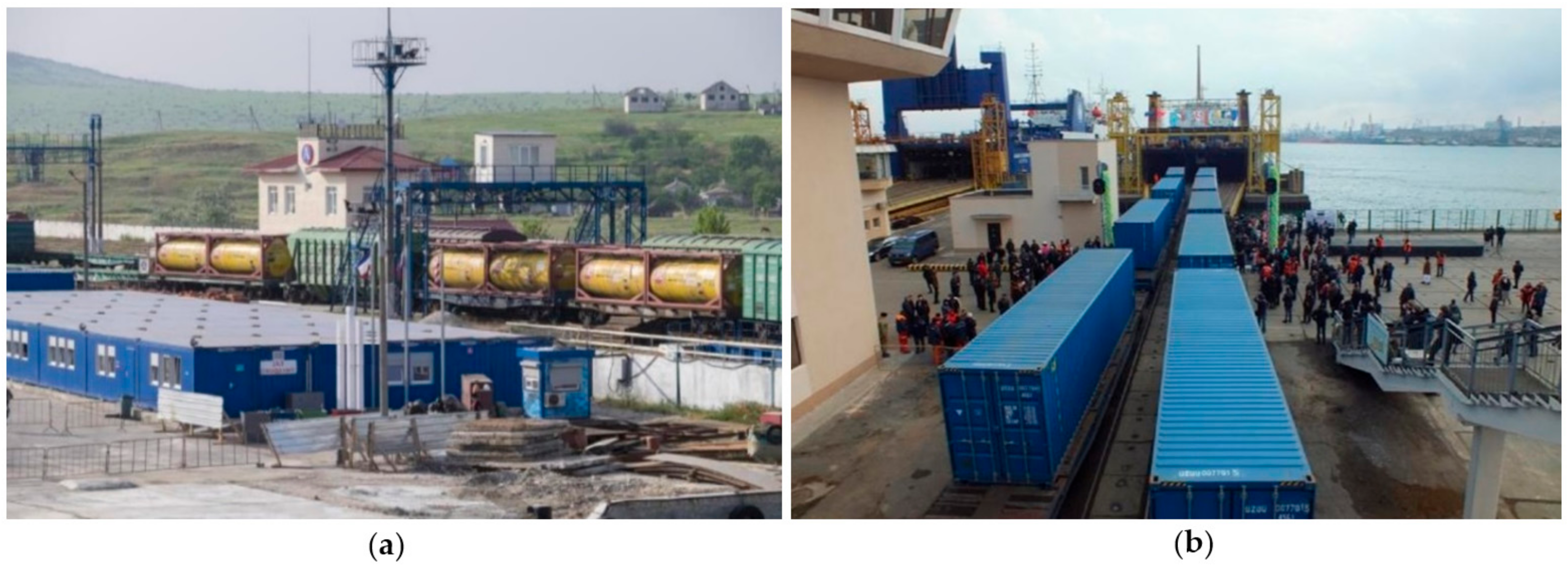
To reduce the time of delivery of goods from the shipper to the consignee, the transportation of mixed trains on rail ferries has become common.
The transportation of goods by rail and ferry services has developed due to the construction of new ferry lines and an increase in the capacity of the ferry fleet, which has been significantly reconstructed and replenished with new ships. Railway ferry services of the countries of the Commonwealth of Independent States (hereinafter—the CIS) are shown in
Table 1.
More than 20 railway crossings with a total length of several hundred kilometres are planned in the near future.
The loading of mixed trains onto the rail ferry in the port is shown in
Figure 3.
The carriage of goods in mixed international rail-ferry traffic is carried out by agreement between rail and sea carriers along the entire route of the cargo in accordance with the current Rules [
20].
In this Regulation [
20], the following abbreviations are used:
SMGS is the Agreement on International Freight Traffic by Rail of November 1, 1951 (if necessary, it is subject to the Agreement between the railway administrations of the CIS member states, the Republic of Latvia, the Republic of Lithuania, and the Republic of Estonia on the special application of certain SMGS norms);
COTIF is the Convention on International Carriage by Rail of 9 May 1980 as amended by the Protocol on Amendments of 3 June 1999;
CIM is the Uniform Legal Provisions for the Contract for the International Carriage of Goods by Rail (Annex B to COTIF);
RID is the Regulation on the International Carriage of Dangerous Goods by Rail (Annex C to COTIF).
Private freight wagons with a track gauge of 1520 mm, owned by legal entities and individuals, including those leased by them in third countries, that meet the technical requirements in force in countries applying SMGS and are equipped with an automatic coupling have these dimensions: when moving with reloading to wagons of a different gauge—1-T,1-VM, 0-VM, 02-VM with axial load no more than 23.5 tons; when moving with the transfer to bogies of a different gauge—0-VM, 02-VM with an axle load of no more than 22.5 tons.
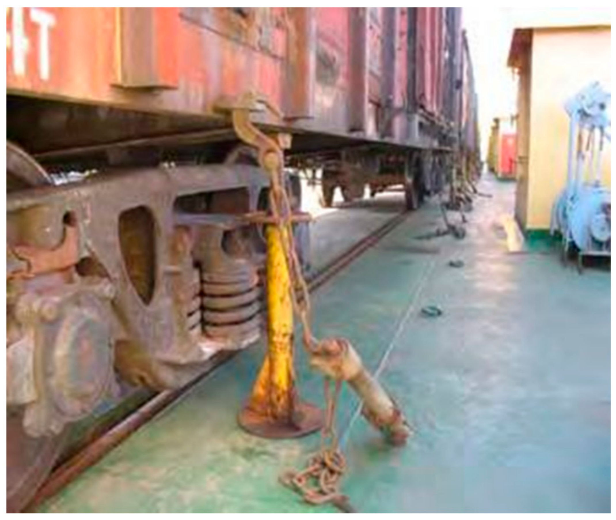
The fastening of containers (tank containers) to the frames of flat cars is carried out according to a standard scheme, that is, by installing fittings on fitting stops.
The fastening and unfastening of wagons on a ferry (
Figure 4), as well as the fastening of wagons in loading and unloading devices during the rolling-off process, are carried out by the forces and means of the ferry according to the technology provided for by the rules of technical operation of the railway ferry.
The largest values of dynamic loads acting on the supporting structures of tank containers and their devices for fastening in operation are determined by the normative documentation, which lays out the UN test systems for portable tanks and MEGCs for dynamic load in the longitudinal direction [
20,
21,
22]. The structure must withstand the effect of its own inertia forces arising from the movement of vehicles, as well as from collisions of cars that occur during shunting operations, including gravity marshalling yard, emergency braking and in other emergency situations that may arise during operation, under such accelerations: 2 g in the longitudinal direction; 1 g in the transverse direction; 2 g in the vertical direction; and in case of impacts: for a loaded container with dangerous goods this value is 4 g; for a loaded container with a safe cargo it is 2 g; for an empty container (in order to check fittings) it is 5 g.
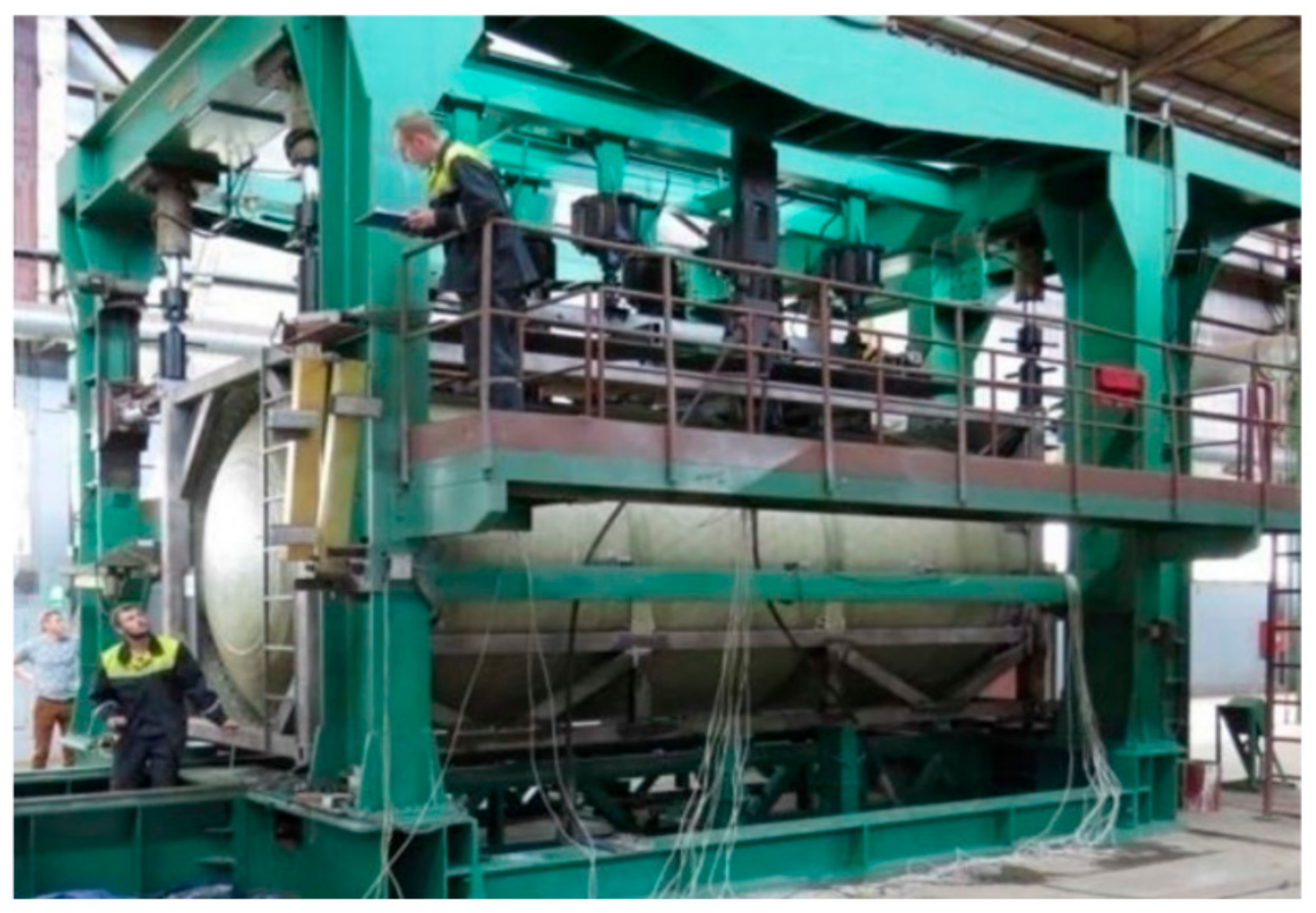
Impact load tests are carried out either with the help of a specialized test rig or using a roll-on striker car onto a test tank container, which is placed on a flat car. The appearance of the test rig is shown in
Figure 5.
However, in practice, the method of rolling a striker car onto a tank container located on a flat car is more preferable, since it allows one to take into account the real efforts that arise when rolling on/rolling off of flat cars with a tank container onto a railway ferry. A brief description of the test procedure and data processing is set forth as follows.
The prerequisite for the start of the tests is the completion of the installation of the measuring circuits and the necessary fittings as well as the readiness of the technical means provided for the tests. The impact is made in such a way that, with a single impact, the shock response spectrum (SRS) curve obtained during the tests for both elbow fittings at the end face subjected to the impact repeats or exceeds the minimum SRS curve at all frequencies in the range of 2 Hz to 100 Hz. Several impacts will be required to achieve this result, but the test results for each impact must be evaluated individually.
The maximum impact force of cars during tests should not exceed 2.2 MN, and the maximum impact speed should not exceed 12 km/h. During the test, the back-up car strikes a platform with a container, standing at a distance of 1.5–2 m from the back-up car (s). The total mass of the back-up car must not be less than R + m, where R is the gross mass of the container and m is weight of the platform on which the container is installed. Four brake shoes are installed under the support car.
Impacts are made at a speed at the time of contact, starting from 2 km/h, with a step of 2–3 km/h until a maximum acceleration of 2 g is reached at each of the corner fittings. After evaluating the results of the previous impact, the speed of the next impact is gradually increased.
The data on the “acceleration-time” dependence obtained for each channel are converted into a shock response spectrum, while the spectra should be presented as a graph of the equivalent static acceleration versus frequency:
The maximum absolute value of the peak acceleration shall be recorded for each of the specified frequency intervals;
The analysis should cover the frequency range of 2 Hz to 100 Hz, and the calculation of the points of the shock response curve should be reproduced in frequency intervals with a step of at least 1/30 octaves. Each point in the interval is a natural frequency, and a damping decrement of 5% should be used within the analysis;
At each collision, the longitudinal forces on the platform frame in the longitudinal direction are recorded, and the maximum values of the accelerations are determined at the fittings;
Research results are assessed by the values of the shock response spectrum (hereinafter—SRS), which must be no less than the standardized values.
The calculation of the points of the SRS curve based on the test results is reproduced in four stages.
At the first stage, a matrix of relative displacements is formed using all data points from the input graph of the “acceleration-time” relationship, which is determined by the formula:
At the second stage, the matrix of relative accelerations is determined using the displacement values according to the formula:
where Δ
t is the time interval between acceleration values;
ωn is the natural frequency without damping;
ωd is the natural frequency with damping;
is the value of the acceleration input data;
ς is the damping coefficient, =0.05 (5%);
i is an integer ranging from 1 to the number of input acceleration data points;
k is a parameter used in the summing up, ranging from 0 to the current value of
i.
At the third stage, the maximum acceleration value from the matrix of relative accelerations (Equation (2)) is fixed for a given frequency interval. This value becomes the point of the SRS curve for that specific interval. This step is repeated for each natural frequency until all eigenfrequency intervals have been estimated.
At the fourth stage, an experimental SRS curve is constructed, which is compared with the minimum standardized SRS curve. The limiting value of the normalized curve is determined by the power dependence according to the formula:
where
is the acceleration in units of
g;
ωn is the natural frequency, Hz.
Further, according to the described methodology, in order to reveal the features of the tests to determine the strength calculations, an experimental tank container was selected. The experimental tank container has a standard size according to ISO and ICC and is designed for the transportation of vegetable oils. A general view of a container car, located on a long-base flat car upon impact, is shown in
Figure 6.
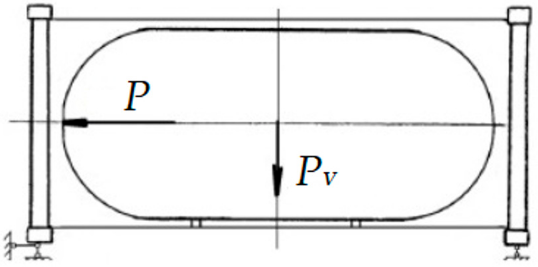
The functional diagram of applying kinematic forces in accordance with the requirements of GOST 31232 [
15] and DSTU 7598 [
16] is shown in
Figure 7.
3. Results
According to the described procedure [
21], a tank container loaded with water up to full carrying capacity, arranged on a flat car, standing in a support and free-standing at a distance of 1.0–1.5 m from the supporter was subjected to impact tests (
Figure 8). This type of test was carried out under the technical supervision of specialists of the organization, which is included in the Shipping Register of Ukraine. The impact test diagram is shown in
Figure 8.
Weight and design characteristics of the test tank container and railway flat car are shown in
Table 2.
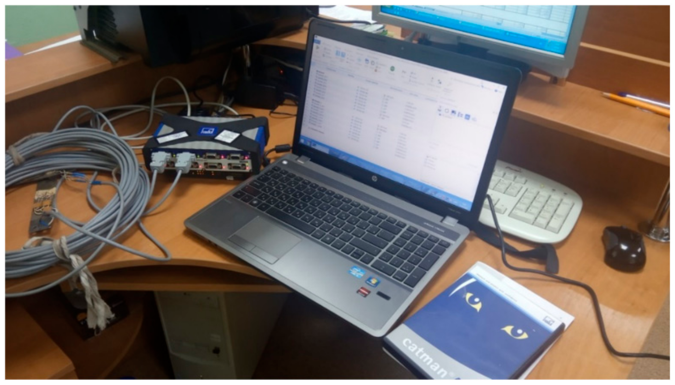
During each impact, the registration and recording of longitudinal forces on the flat car frame and acceleration in the longitudinal direction are performed using a measuring system, which includes: a personal computer, cables, a signal amplifier and accelerometers (vibration transducers). Data processing was carried out on a computer using standard software with statistical processing of processes (
Figure 9).
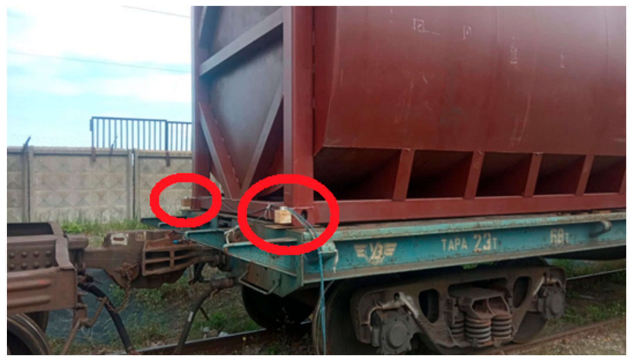
The registration of the container acceleration processes is determined by accelerometers (vibration transducers) with a minimum amplitude range of 200 g, with a maximum lower frequency limit of 1 Hz and a minimum upper frequency limit of 3000 Hz, installed on the lateral faces of two adjacent fittings from the impact side (
Figure 10).
The impact was performed in such a way that, under a single impact, the SRS curve obtained during the tests for both fittings subjected to the impact repeated or exceeded the minimum SRS curve at all frequencies in the range of 2 Hz to 100 Hz.
Analysis of the obtained oscillograms showed that the shock pulse is a short-term, rapidly extinguishing process. For computational studies, each oscillogram was presented in the “acceleration-time” coordinates (
Figure 11).
Each experiment (impact) has undergone a previous treatment, which consists of the following:
The initial data for further computational studies are as follows: the number of the experiment, the impact force, the number of sections for breaking the shock pulse, the pulse duration of each section, the distribution of natural frequencies into sections.
The matrices of relative displacements and accelerations were calculated with a step Δt = 0.00067 s.
Similar calculations were performed for all time intervals of each experiment; calculation results of SRS are shown in
Table 3 and
Table 4.
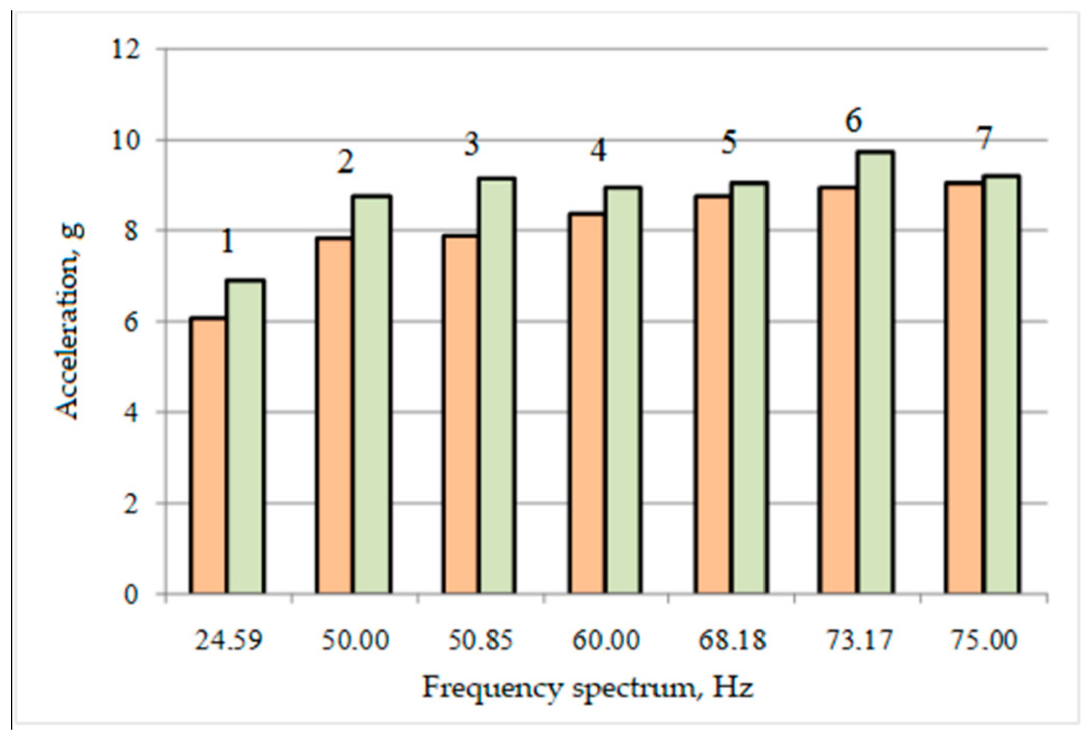
A comparative histogram of the SRS values for the obtained natural frequencies shows that their values exceed the normalized values (
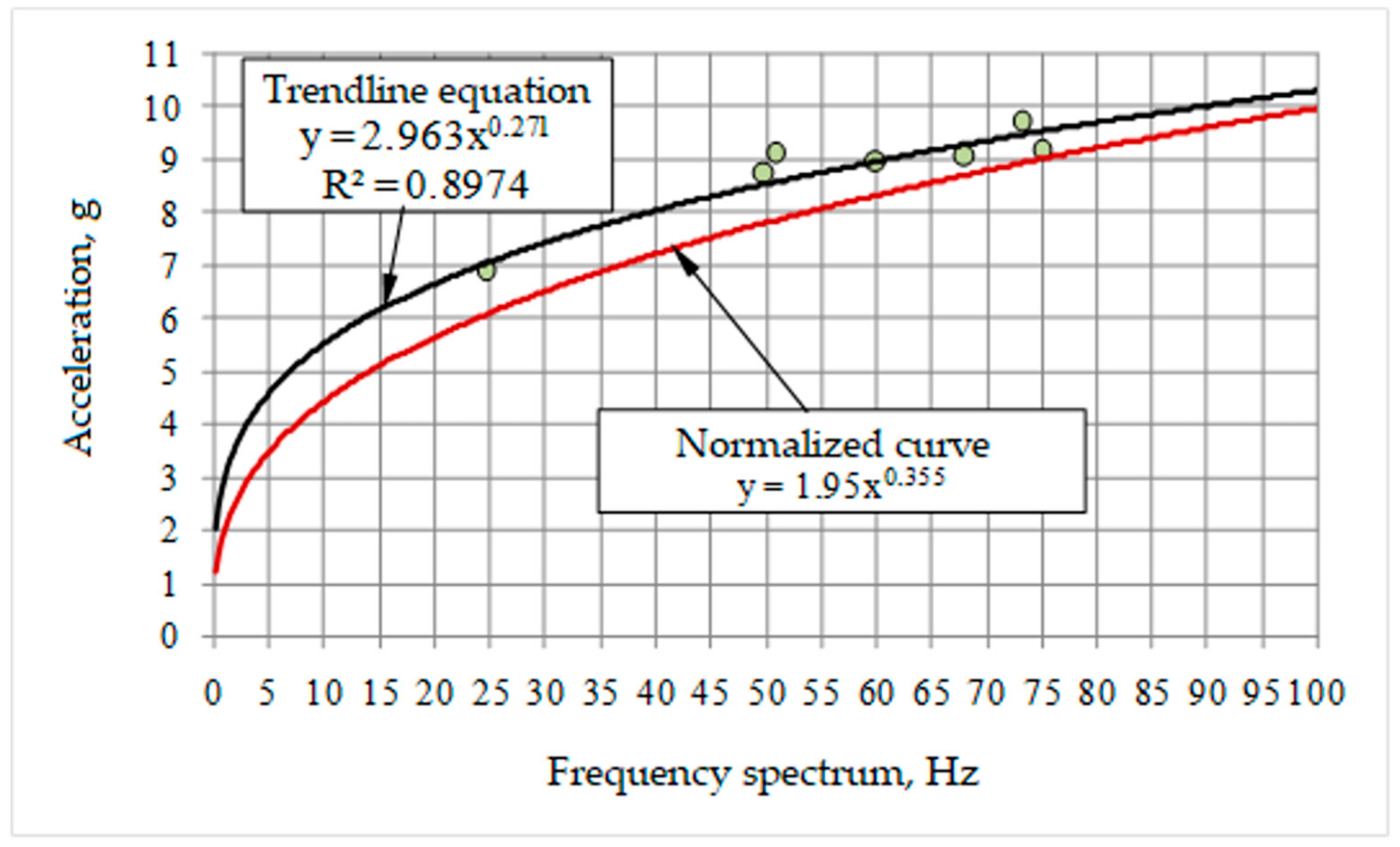
Figure 12). The equation of the experimental SRS curve in the frequency range 0–100 Hz is described by power-law dependence. Equation coefficients were determined by the statistical method of maximum likelihood, while the coefficient of determination was 0.897, which is a satisfactory value. Comparative analysis has shown that the experimental SRS curve in the frequency range 0–100 Hz exceeds the normalized curve (
Figure 13).
Obviously, Equations (1) and (2) convert the shock pulse into a harmonious wave process, which is typical for imitating the action of sea waves on a container during transportation by sea vessels.
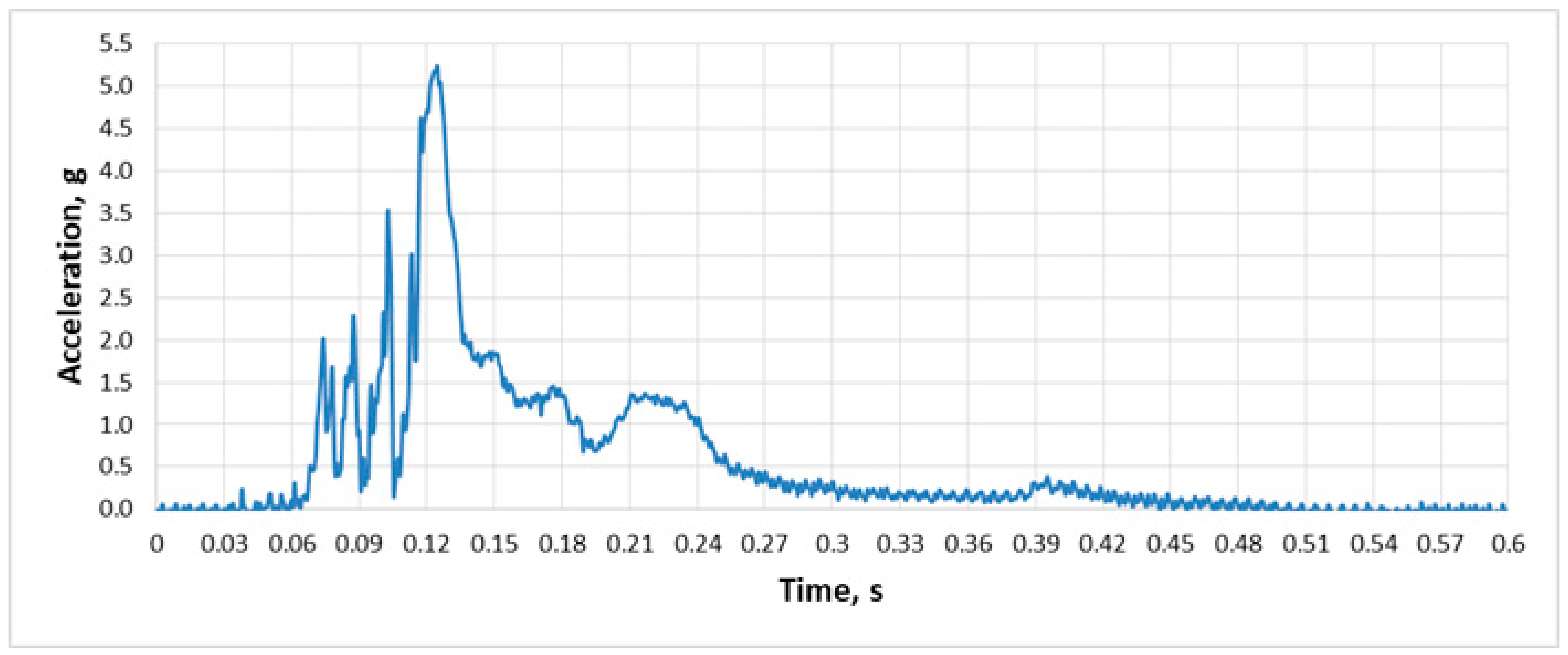
It should be noted that the force of the impact action implemented on a railway carriage is a high-frequency, rapidly decaying pulse with a duration of no more than 1 s, as shown by the raw accelerometer data in
Figure 14.
As mentioned earlier, such a feature of the impact action requires a larger number of experiments (impacts); moreover, for a typical impact flow chart, it is almost impossible to obtain a natural frequency of less than 50 Hz. To solve this problem, it is proposed to use a tank car with bulk liquid, the processes in which upon impact differ significantly from other freight wagons.
At the time of shock action, a longitudinal inertia force acts on the liquid in the tank, which causes a short-term but significant pressure of the liquid (hydraulic shock) on the front bottom. The hydraulic shock pressure depends on many factors:
The speed of the movement and acceleration of the striker car at the moment of impact, as well as its mass;
The density and dynamic viscosity of the liquid poured;
The level of liquid underfilling in the tank car.
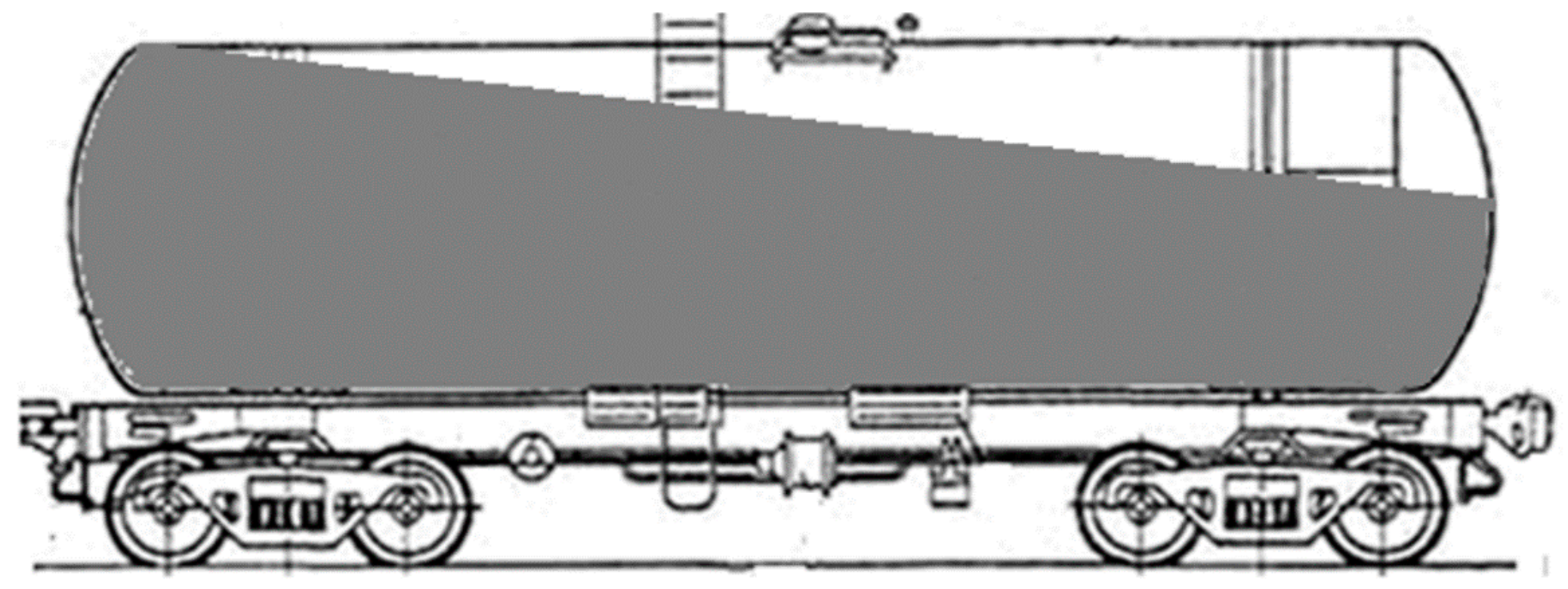
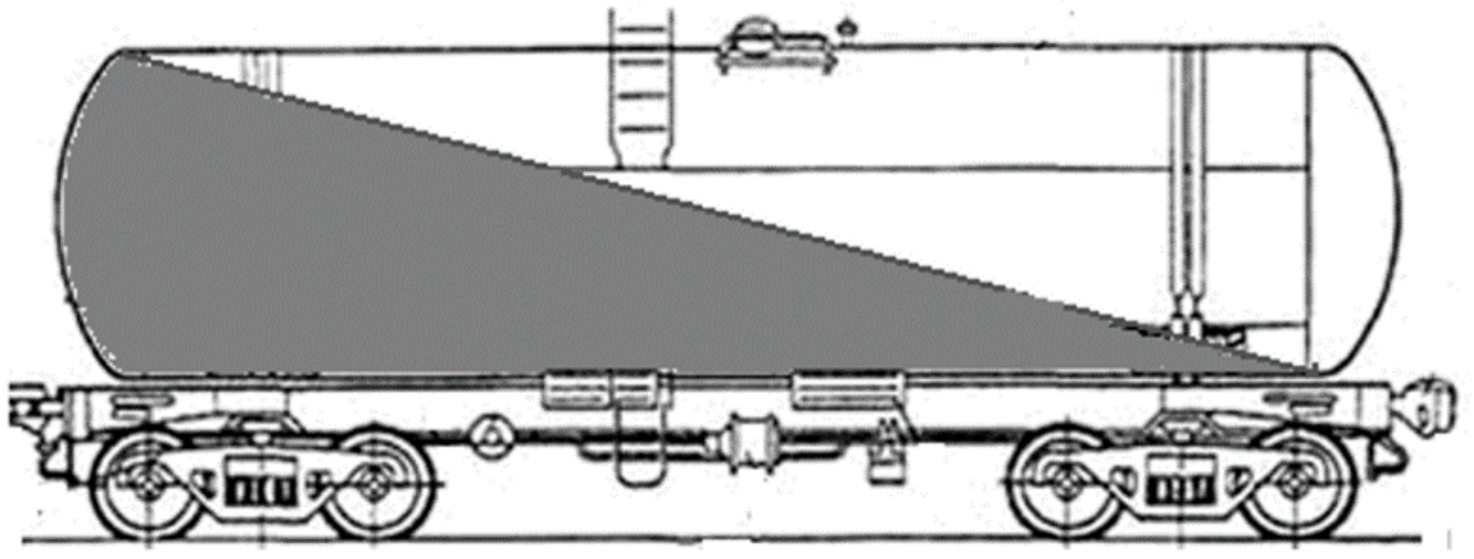
Hydraulic pressure in a fully (
Figure 15) and partially (
Figure 16) loaded tank car has significant differences.
It was found that in a barrel with partial underfilling, wave processes of liquid occur, caused by periodic inertial overflow of liquid from one end of the barrel (bottom) to the other (bottom).
Periodic shock effects on the tank, caused by fluid vibrations, make it possible to use it for testing the tank container.
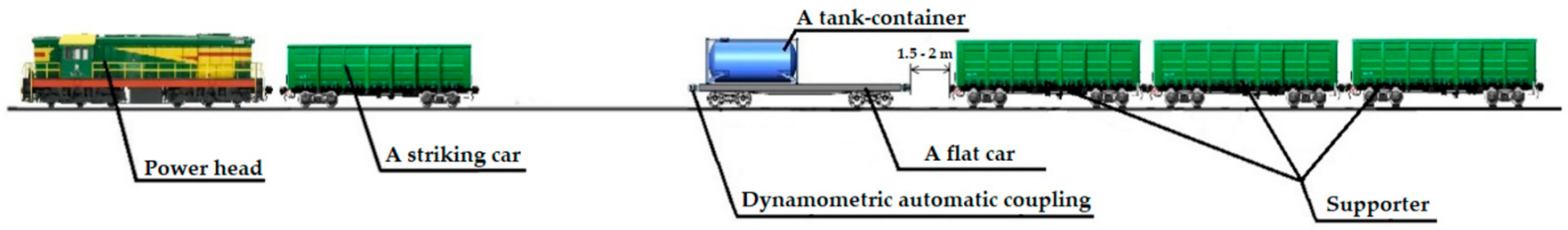
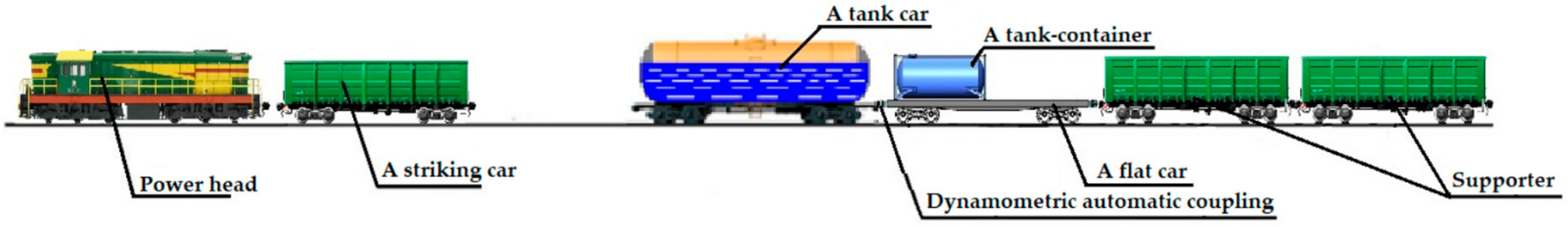
In this regard, the following test configurations for tank containers are proposed (
Figure 17):
1. A train formation consisting of a tank car and a railway flat car with a tank container placed on it is formed;
2. A flat car with a tank container placed on it is fixed on the railway track with brake shoes on both sides;
3. The tank car is filled only with water up to 2/3 of the barrel’s own volume [
22];
4. Tests are carried out by rolling the striker car onto the tank car.
The forces that will act on the container upon impact can be calculated as follows. Fittings are rigidly connected to the platform by welding and, therefore, all dynamic processes of the platform, as an elastic body, will affect the fittings.
Since there are no wave processes on the surface of the liquid when the barrel is at full capacity (the liquid is incompressible), the container tank can be viewed as a perfectly rigid body in relation to the platform. The inertia force exerted on the centre of gravity of the container is determined by the formula:
where
Fy = 2315.16 kN is the impact force on the platform (see
Figure 11);
Fu,k is the inertia force acting on the container;
mk = 37 t is the container weight;
mpl = 21 t is the platform weight. Taking into account the weight characteristics, the inertia force of the container will be:
and the acceleration of the container will be:
The calculations showed that the acceleration of the container (4.07 g) differs from the acceleration of the platform (5.22 g, see
Figure 11) by 22% downward.
The maximum pressure (hydraulic shock) realized near the bottom of the boiler of the container located on the side of the impact (on the opposite side, the pressure is zero) is determined by the formula:
where
Dk is the diameter of the barrel,
Dk = 2.896 m. The container inertia force applied to the container’s centre of gravity creates a moment relative to the front fittings, which causes additional vertical loads on the front fittings. The vertical inertia load on the front fittings is given by:
where
Fuk is the inertia force of the container;
Dk is the barrel diameter;
Lk is the container length. Thus, the total vertical load on the front fittings, taking into account the weight characteristics of the container, will be:
Thus, at the rear fittings, the vertical force will be equal to:
In this case, the rear fittings will be unloaded (
Figure 18), and the cantilever portion of the platform is exposed to significant vertical forces.
Taking the coefficient of friction between the metal of the container and the metal of the platform equal to 0.25, the friction force between the container and the platform will be:
High frictional forces can block the longitudinal movement of the container relative to the platform.
Subject to further substantiation of the validity of the proposed test configuration, it is possible to consider the issue of making additions to the existing standard test procedure in order to reduce the time and financial resources for conducting research.
4. Conclusions
Based on the analysis of the research carried out, the following conclusions can be drawn:
It has been established that tests of portable tank containers to confirm the ability to withstand impact in the longitudinal direction are carried out in accordance with the requirements of the UN Navigation Regulations. In accordance with these regulations, tests are carried out on a specialized test rig, or using a railway flat car, by impacting the striker car on a flat car with a tank container.
Based on the existing typical procedure, studies were carried out on the ability of an experimental tank-container to withstand the impact in the longitudinal direction, according to the results of which it was established that the experimental tank-container under study meets the current regulatory requirements.
With the existing typical research scheme, conditionally high-frequency and short-term shock pulses are generated, with a frequency of natural oscillations in the range 50–100 Hz. At the same time, the receipt of shock pulses with a natural frequency of 2 to 50 Hz is unlikely.
It has been established that when using a typical test configuration to plot the SRS curve in the frequency range of 2 Hz to 100 Hz, a significant number of impacts (shocks) are required; as a result, significant costs and time are required to conduct such studies. The obtained equation of the experimental SRS curve in the frequency range 0–100 Hz for an experimental tank container is described by power-law dependence.
It is shown that the frequency of natural vibrations does not depend on the force of impact and the speed of the striker car run.
A functional diagram for the strength testing of a tank container is proposed, in which shock effects on a flat car are realized by rolling a striker car on a tank car, which in general will reduce the research time as well as reduce costs and improve the existing typical research technique. The proposed test configuration requires preliminary studies to confirm the possibility of its use and further recommendations for its use.
These studies will contribute to the construction of tank containers with improved strength characteristics, as well as the improvement of the test configuration for tank containers under longitudinal shock loads.


 ,
, 


