Article

Evaluation of Localized Necking Models for Fracture Prediction in Punch-Loaded Steel Panels

1
Department of Naval Architecture and Ocean Engineering, Inha University, Incheon 22212, Korea
2
Offshore Plant Research Division, Korea Research Institute of Ships and Ocean Engineering, Daejeon 34103, Korea
*
Author to whom correspondence should be addressed.
J. Mar. Sci. Eng. 2021, 9(2), 117; https://doi.org/10.3390/jmse9020117
Submission received: 24 December 2020 / Revised: 12 January 2021 / Accepted: 21 January 2021 / Published: 25 January 2021
(This article belongs to the Special Issue Ocean and Shore Technology (OST))

Abstract

:
This study compared the experimental test results on punch-loaded unstiffened and stiffened panels with numerical predictions using different localized necking modeling approaches with shell elements. The analytical models that were derived by Bressan–Williams–Hill (BWH) were used in their original form and extended version, which considers non-proportional loading paths while using the forming-severity concept and bending-induced suppression of through-thickness necking. The results suggest that the mesh size sensitivity depends on the punch geometry. Moreover, the inclusion of bending effects and the use of the forming-severity concept in the BWH criterion yielded improved estimations of fracture initiation with shell elements.

1. Introduction

The assessment of a ship’s hull structure to withstand collision and stranding loads has traditionally been based on the application of a limit equivalent (effective) plastic strain in non-linear finite element analysis, without any explicit considerations of the structural processes, including through-thickness necking and associated ductile fracture. This approach, which is commonly coupled with mesh/element size-based scaling, has a certain accuracy when applied to predict plating rupture [1]. On the other hand, practitioners have generally recognized the need for more accurate fracture prediction methods, which are applicable to shell elements, involving calibration that can be performed readily while using the available hardening properties of the material and considering the likely failure modes [2,3,4]. Recent attention has been given to characterizing the ductile fracture response of marine structural steels [5,6,7,8] and simulating fracture with shell elements in maritime crash scenarios while using advanced fracture models [9,10,11,12,13,14,15,16]. Through-thickness necking and subsequent fracture is the dominant failure mechanism in punch-loaded plated structures, as observed in the later studies.
A serious obstacle to the accurate simulations of actual fracture phenomenon induced by localized necking using shell elements is the plane-stress condition assumption and mesh size effects in the post-necking regime. Adopting a forming limit curve (FLC) with the assumptions on the post-necking response and mesh size effect is a straightforward approach for predicting this failure mechanism with shell elements [10,17,18]. Research related to fracture prediction with shell elements [12,13,19] confirmed that the assumption of incipient necking as a failure condition for plates under biaxial membrane stretching is reasonable, provided that an element size that is several multiples of the plate thickness is used. Nevertheless, challenges remain when using FLCs, because the finite element analysis predictions tend to be sensitive to the numerical implementation of the localized necking condition [13,20].
This study examined the influence of different numerical implementations of FLCs on fracture predictions with shell elements in punch-loaded stiffened panel simulations. The well-known BWH (Bressan–Williams–Hill) criterion by Alsos et al. [18] was used as a reference. Punching tests on unstiffened and stiffened panels reported in the recent literature were used to evaluate the predictions of the instance of fracture. Furthermore, the influence of the bending and loading history effects are discussed.

2. Localized Necking Prediction

2.1. Preliminaries

In this study, the J 2 plasticity with the associative flow rule and isotropic strain hardening was assumed. The plane stress condition holds, because shell elements are used. The von Mises yield condition can be expressed as
f σ , k = σ ¯ k = 0
where k is the deformation resistance and σ ¯ is the von Mises equivalent stress under the plane stress condition, which is expressed in terms of the principal stresses σ 1 , σ 2 , as follows:
σ ¯ = σ 1 2 + σ 2 2 σ 1 σ 2
As the deformation resistance function, a modified version of the Swift hardening law [21] was adopted, as follows:
k ε ¯ p = σ 0 if ε ¯ p ε ¯ L K ε 0 + ε ¯ p n if ε ¯ p > ε ¯ L
where σ 0 is the initial flow stress, ε ¯ L is Lüders plateau strain, and K, n, and ε 0 are the Swift law parameters. The equivalent plastic strain, ε ¯ p is defined as the work-conjugate of the equivalent stress, σ ¯ . Note that strain rate effect is omitted in the present study, because it has a marginal influence on global structural response and fracture initiation in low-velocity impact problems, such as ship collisions [13].
The stress state or loading path is usually described while using the ratio of principal plastic strains ( ε 1 , ε 2 ) :
α = ε 2 ε 1
Alternatively, the principal stress ratio may be used, which is defined as
β = σ 2 σ 1
Following the assumption of J 2 plasticity with the associative flow rule and proportional loading, it may be shown that the following relation holds between α and β :
α = 2 β 1 2 β
and, inversely,
β = 2 α + 1 2 + α
Furthermore, under plane stress condition, stress triaxiality is defined as
η = σ m σ ¯ = σ 1 + σ 2 3 σ ¯
where σ m is the mean stress. Note that σ 3 = 0 .
The relationship between the stress triaxiality and other stress state parameters, α and β , can be written, as follows:
η = α + 1 3 ( α 2 + α + 1 ) = β + 1 3 β 2 β + 1
Similarly, an inverse relationship between α and η can be written as
α = 0 , if η = 1 / 3 3 η 2 + 3 η 3 η 2 3 η + 2 2 2 3 η 2 1 , otherwise
The principal major strain, ε 1 , can be transformed into the equivalent plastic strain, as follows:
ε ¯ p = 2 ε 1 3 1 + α + α 2
The last useful equation is between the equivalent von Mises stress and major principal stress, σ 1 , which is given, as follows:
σ 1 = σ ¯ 1 β + β 2

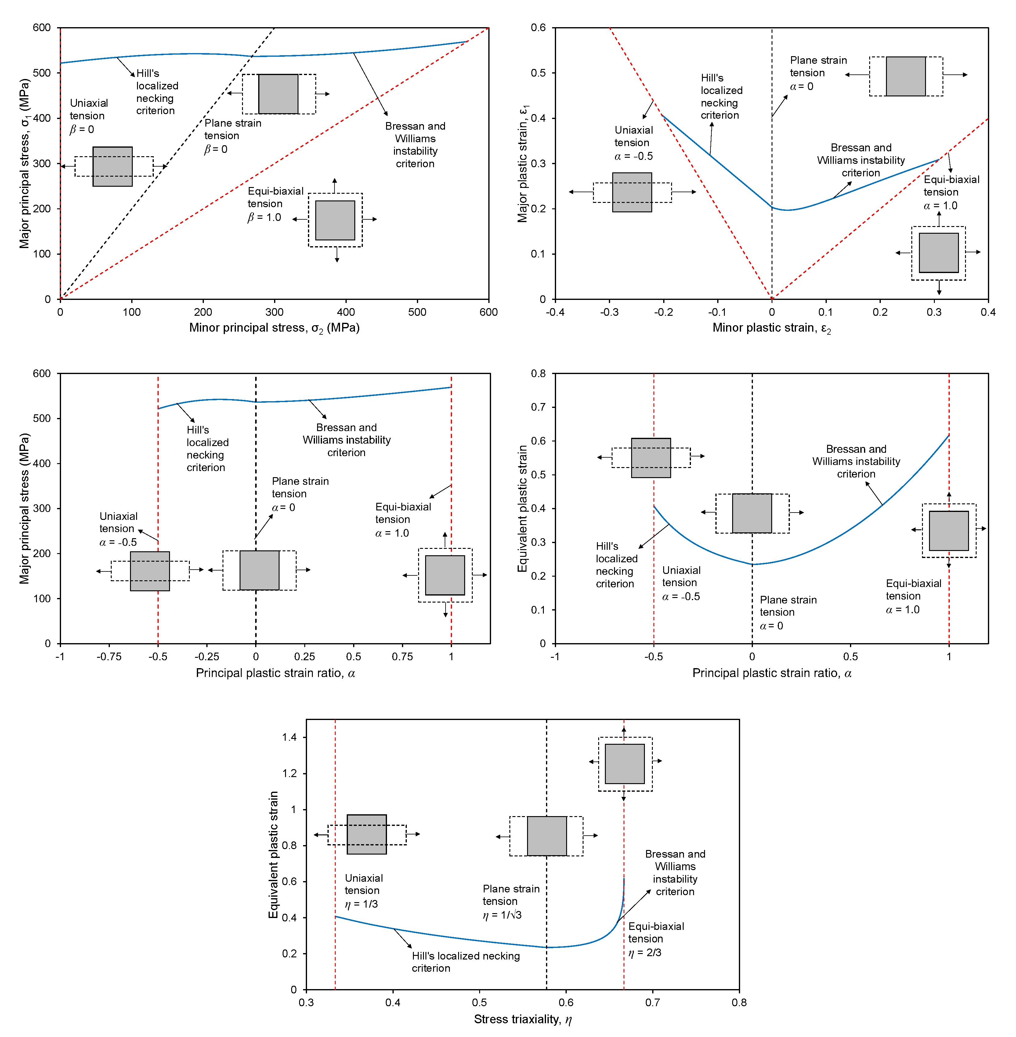
2.2. Bressan-Williams-Hill Model

The BWH model forwarded by Alsos et al. [18] to predict fractures with shell elements combines Hill’s localized necking criterion, which is valid in the second quadrant of the forming limit diagram ( 0.5 < α 0 ), and Bressan and Williams’ shear instability-based localized necking criterion [3], which is used for the first quadrant ( 0 α < 1.0 ). Alsos et al. [18] presented this criterion in a rather unconventional space of the principal stress-principal strain ratio, as follows:
σ 1 , n α = 2 K 3 1 + 0.5 α 1 + α + α 2 2 3 ε ^ 1 1 + α 1 + α + α 2 , for 0.5 α 0 2 K 3 2 3 ε ^ 1 n 1 α 2 + α 2 , for 0 α 1
where ε ^ 1 is a major necking strain that corresponds to the plain strain tension state ( α = 0 ). While using a power-law hardening function (Holloman type), it can be assumed to be the hardening exponent n. In the above equation, K and n are the power law hardening parameters.
The BWH criterion can be transformed into the spaces, ( σ 1 , σ 2 ) , ( ε ¯ p , α ) , and ( ε ¯ p , η ) , while using the transformation equations presented in the previous subsection. Figure 1 shows the plots of the BWH criterion for mild steel in various variable spaces. Based on the arguments of Stoughton [22,23], Alsos et al. [18] suggested that a stress-based forming limit diagram (FLSD) is less sensitive to the non-proportionality of strain (loading) paths and advocated while using the BWH criterion expressed in the space of ( σ 1 , α ) . If the stress state, which is characterized by either stress triaxiality ( η ) or principal plastic strain ratio ( α ), remains constant to failure. The loading path (strain path) is then said to be proportional. If the stress triaxiality changes throughout the loading, the loading path is non-proportional. Hence, a proportional loading path means that the direction of the stress vector does not change.
In the original finite element numerical implementation of the BWH criterion, incipient necking is assumed to occur if the major principal stress at the mid-layer through-thickness integration point of a shell element satisfies the following condition:
σ 1 σ 1 , n [ α ] 1
Note that the formulation does not consider the stress and strain histories, because it only refers to the current stress state and major principal stress.
The failure condition is checked at the mid-layer of a shell element in order to ensure that only membrane loading is considered. Therefore, in its original form, the BWH criterion is a local-failure criterion for shell elements. For checking the BWH criterion at the mid-layer of the shell element, the through-thickness integration point at the mid-layer is used. In Abaqus, by default, the Simpson integration rule is used for the thickness integration of a four-node, reduced integration shell element (S4R in Abaqus element library). The default number of section points is five. The first section point refers to the bottom surface of the shell element and the fifth section point refers to the top surface of the shell element. Likewise, the third section point refers to the mid-layer of the shell element. A user-defined material subroutine VUMAT combined with the subroutine vumatXtrArg is used to access the state variables of the through-thickness integration points.

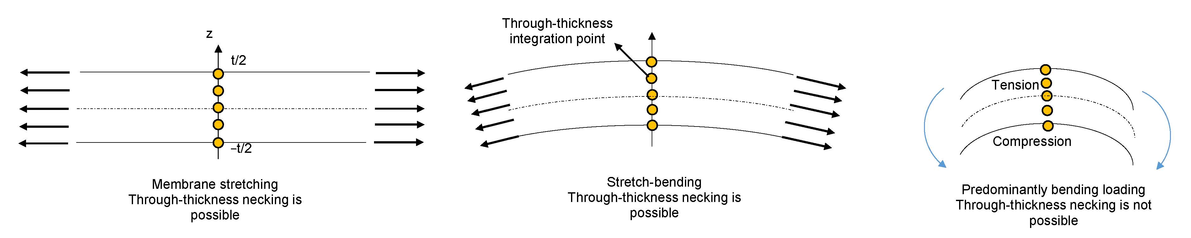
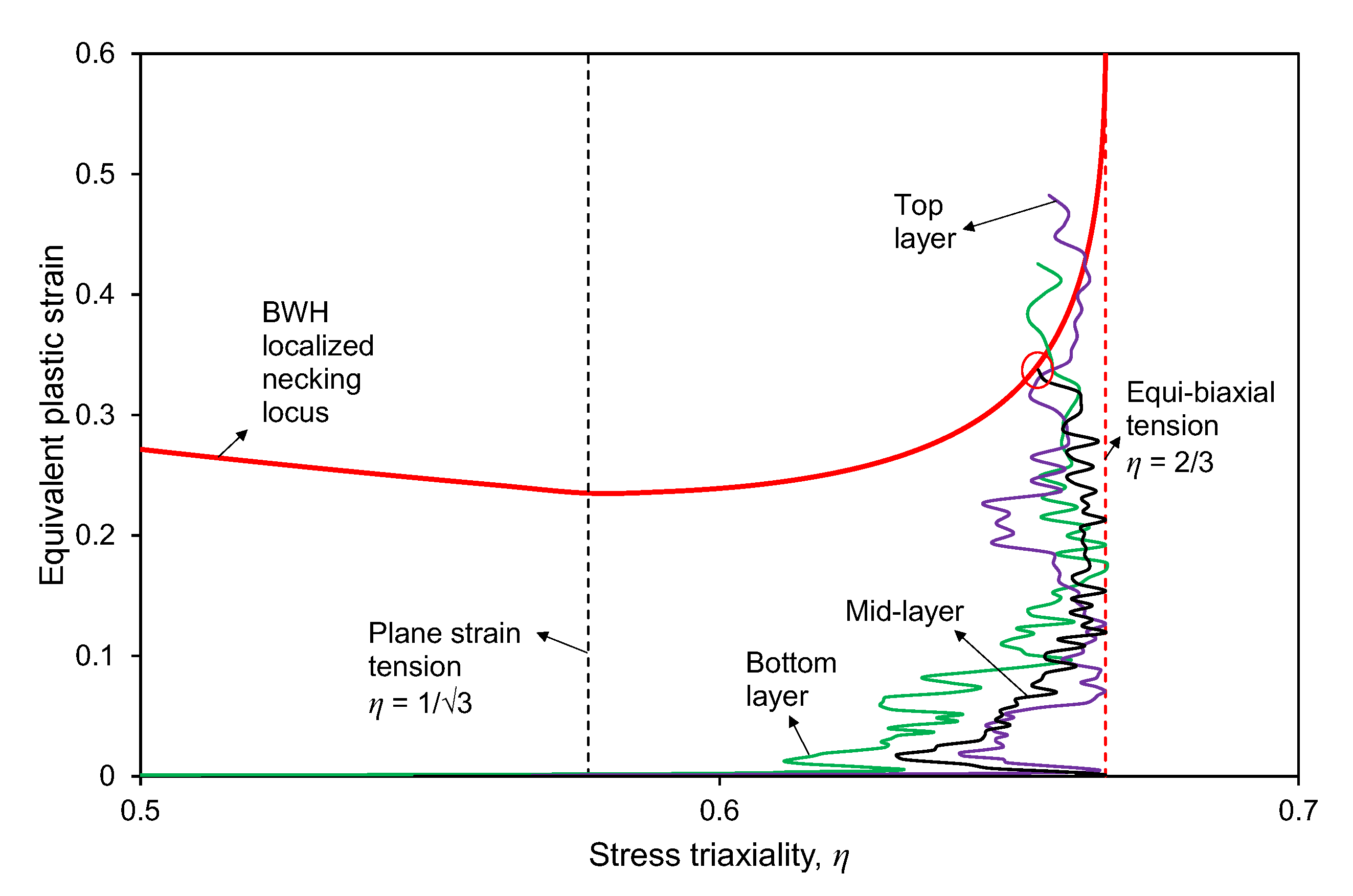
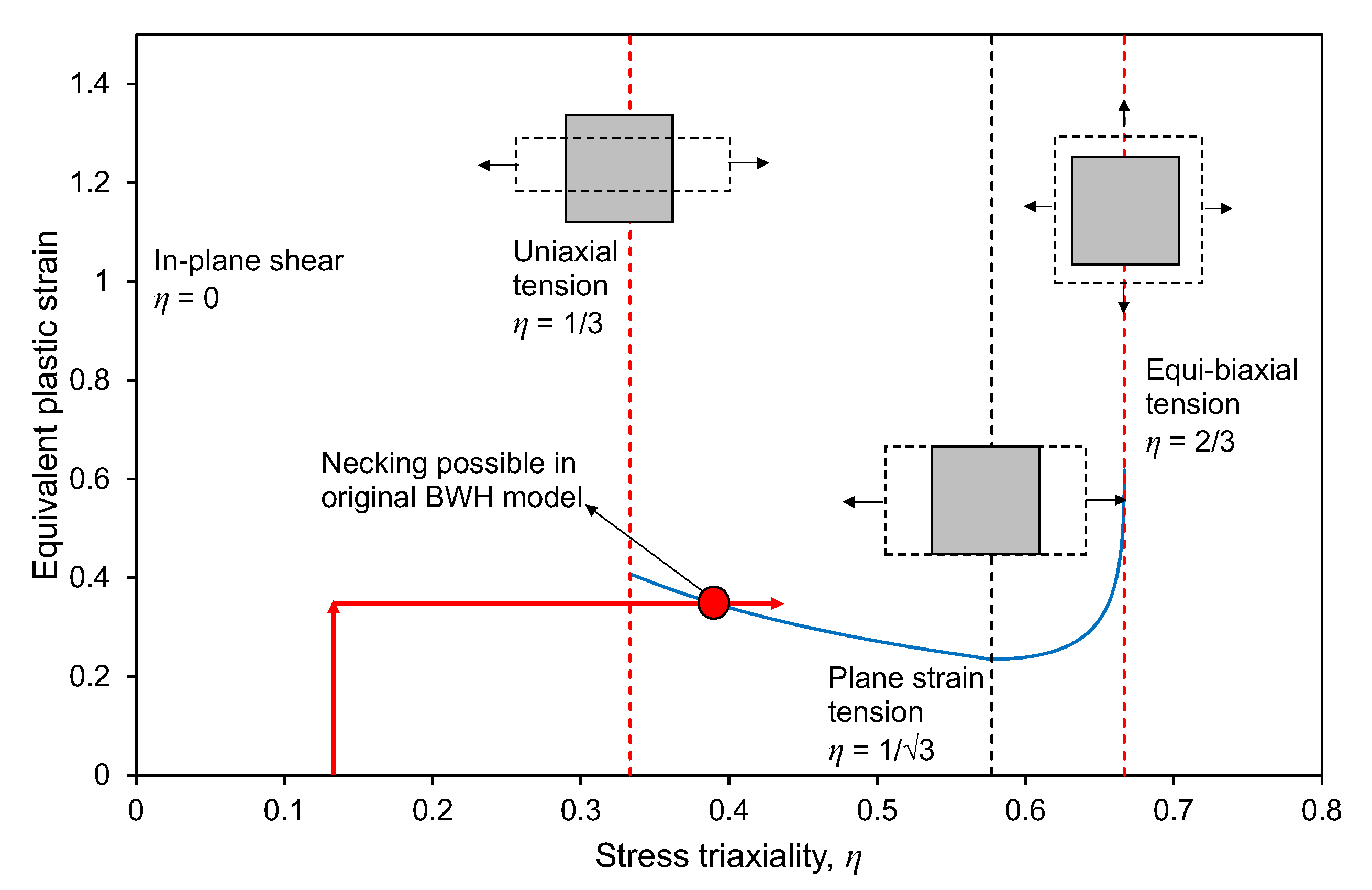
2.3. Alternative Implementation of the BWH Model

Earlier studies, such as Storheim et al. [10], reported that the BWH criterion predicts the displacement to fracture initiation conservatively. Previous extensions of the BWH criterion [10] treated the post-necking response, which was omitted in the original BWH criterion and was attributed as the source of the conservative failure prediction. On the other hand, no attention was given to the bending-induced delay of incipient localized necking and non-proportional loading path effect, which may be a more serious drawback of the original BWH criterion when compared to the omission of the post-necking response. An alternative numerical implementation of the BWH criterion addressing these two points has been presented in [16] and adopted in the present study for further evaluation and validation.
First, the BWH criterion was transformed into the space of the equivalent plastic strain-stress triaxiality. Thus, it can be used as a failure locus in the damage indicator framework to handle the non-proportional loading path function [24]. In addition, this format is more convenient to implement in a user-defined material subroutine, because the equivalent plastic strain is calculated directly in the plasticity part of the subroutine. Figure 1 shows the lack of resolution of the localized necking locus in the space of ( σ 1 , α ) , as used in the original implementation of the BWH criterion. This provides further motivation to transform the BWH criterion into ( ε ¯ p , η ) space, which is more convenient for numerical implementation.
Instead of referring to the stress state in the final state at incipient necking as a failure condition, as indicated in Equation (14), a localized necking indicator is defined, which accumulates with increasing equivalent plastic strain and it is weighted with the instantaneous forming limit, depending on the current stress state. This concept is called the forming severity by Bai and Wierzbicki [24]. The necking indicator, d N , can be expressed, as follows:
d N = d ε ¯ p ε ¯ n [ η ] for 1 / 3 η < 2 / 3
where d ε ¯ p is the equivalent plastic strain increment and ε ¯ n [ η ] is the localized necking locus that is expressed in ( ε ¯ p , η ) space.
Figure 2 presents the modeling of localized (through-thickness) necking while using shell elements. In the case of stretch-bending, before membrane stretching, the through-thickness integration points will experience different loading paths, because some will be initially under compression. This will cause a delay in incipient necking in the stretching stage. Under a predominant bending load, the integration points on the compression side will not satisfy the necking condition that is given in Equation (15). Therefore, incipient necking will occur if the necking indicator, N, reaches unity in all individual thickness integration points. This condition can be expressed as [12,13,14,15,19]:
N ( z ) 1 z t / 2 , t / 2
where t is the shell element thickness. Note that the stress tensor components for a particular integration point are not set to zero, unless all other through-thickness integration points meet the necking condition. This approach was first proposed by Stoughton and Yoon [25], who showed that considering the stress distribution through the thickness of the sheet metal can aid in identifying the mode of failure, which is localized necking preceding fracture and fracture without localized necking (surface cracking or shear fracture). They emphasized that a localized necking criterion requires confirmation that all the layers through the shell thickness exceed the localized necking limit that applies to in-plane tension. Li et al. [26] demonstrated that through-thickness analysis of shell elements is also useful for simulating crack propagation, due to bending, which is not considered by a forming limit curve. However, as explained in the introduction, in the present work, this type of failure is omitted.
This extension of the BWH model is denoted as BWH-E and it is implemented in a user-defined material subroutine, VUMAT, combined with the vumatXtrArg subroutine to access all of the integration point state variables. A common array, external to the VUMAT, is included to store the status of each element, which is checked at every time increment for each through-thickness integration point.

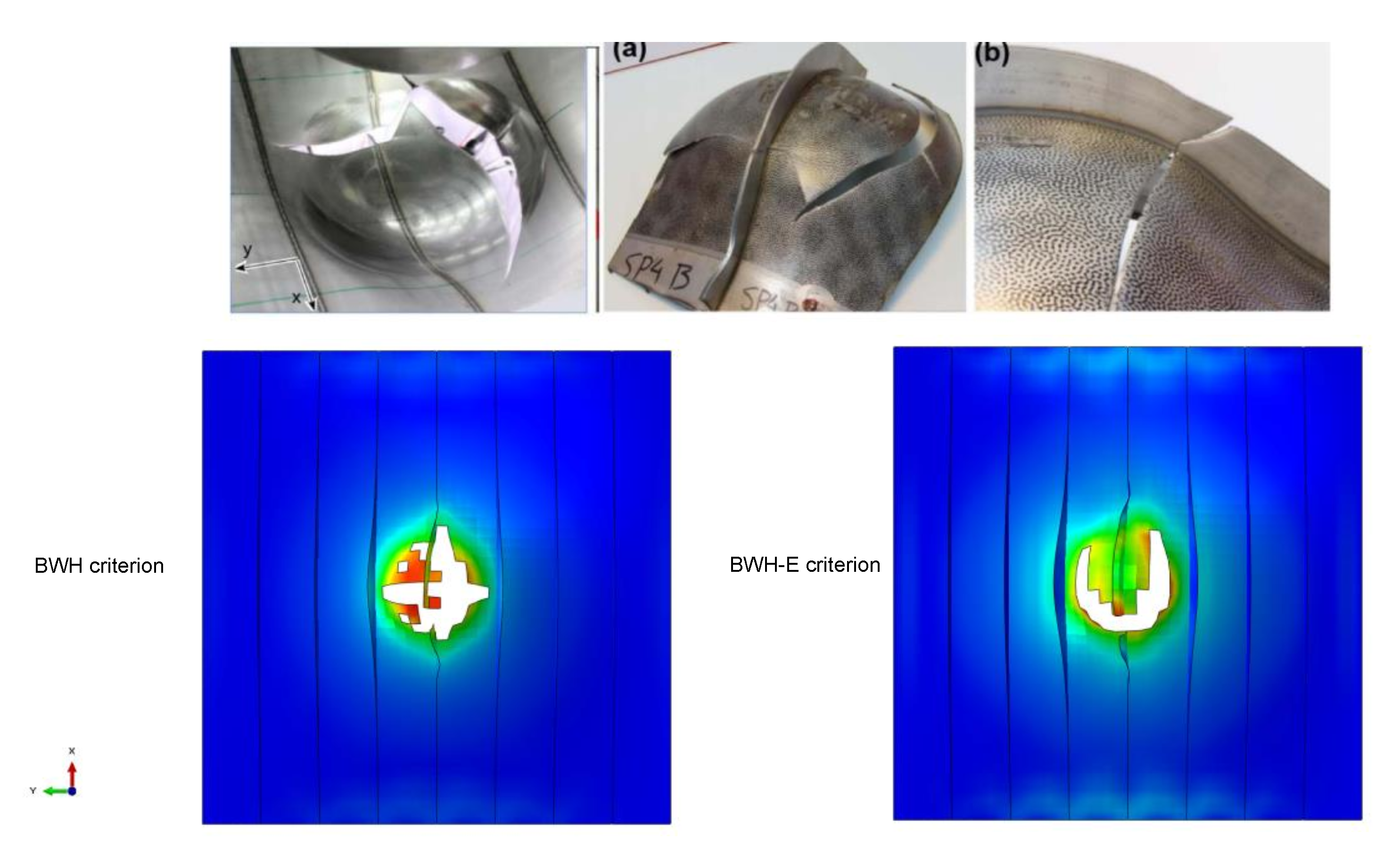
3. Simulation of Panel Penetration Tests

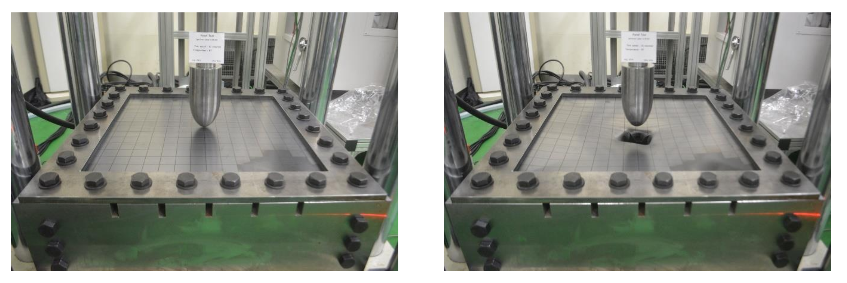
3.1. Description of the Tests

The predictions of the original BWH model and the proposed numerical implementation (BWH-E) were compared by simulating the unstiffened panels that were reported by Park and Choung [27] and laser-welded stiffened panel penetration tests reported by Kõrgesaar et al. [28].
The unstiffened panels in [27] were made of JIS G3131 SPHC grade hot-rolled 1.9 mm think plates. The hardening law parameters were determined to be K = 624.2 MPa, n = 0.194 , ε 0 = 0.000112 , σ 0 = 312.72 MPa, and ε ¯ L = 0.02825 . In total, two tests were performed. Figure 3 shows the experimental setup and the ruptured plate at the end of one of the tests. The punch had an ellipsoidal surface. The semi-major and -minor axis radii were 100 and 50 mm, respectively. The plate panels were square and they had unclamped dimensions of 600 × 600 mm. The tests were conducted in a quasi-static manner with an indentation speed of 10 mm/min. The panels were bolted on a support jig while using a 5 mm thick clamping plate and bolts. No slipping occurred during the tests.
The stiffened panels that were tested by Kõrgesaar et al. [28] were 1200 × 1200 mm square plates made from S235JR grade steel, with the following hardening law parameters: K = 630 MPa, n = 0.21 , ε = 0.0073 , σ 0 = 275 MPa, and ε ¯ L = 0.012 . These parameters were experimentally obtained from a previous study [28]. Flat-bar stiffeners with a 30 mm web height and 120 mm spacing were welded using a laser-welding technique. The plate and stiffeners were both 3 mm. The test panels were bolted on the testing frame with clamping plates and back support plates. The unclamped dimensions of the panels were 960 × 960 mm. A hemispherical punch with a 120 mm radius was forced to penetrate the center of the test panels with a velocity of 10 mm/min. The punch surface was polished in order to minimize the friction effects. Five penetration tests were conducted; four of them focused on center indentation. Following a previous study [28], the force-displacement curve and photographs of the test panel, denoted as SP4, were taken as a reference to compare with the numerical simulations.

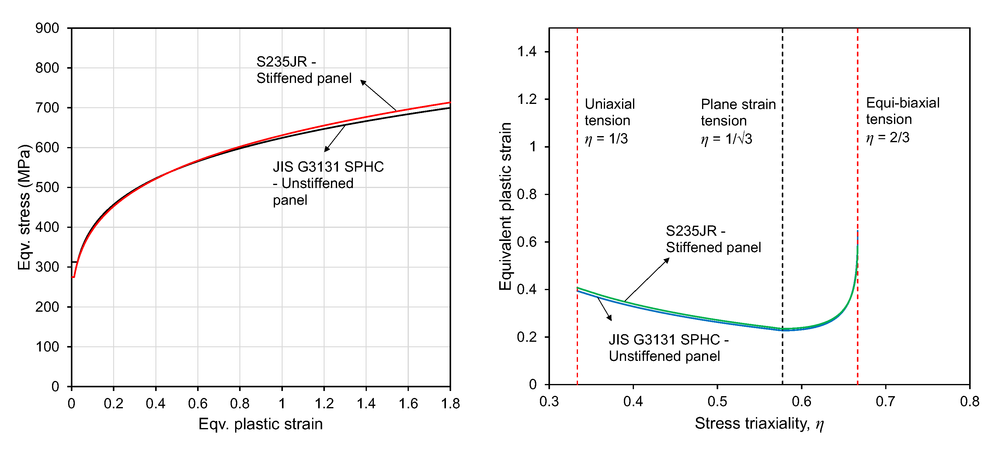
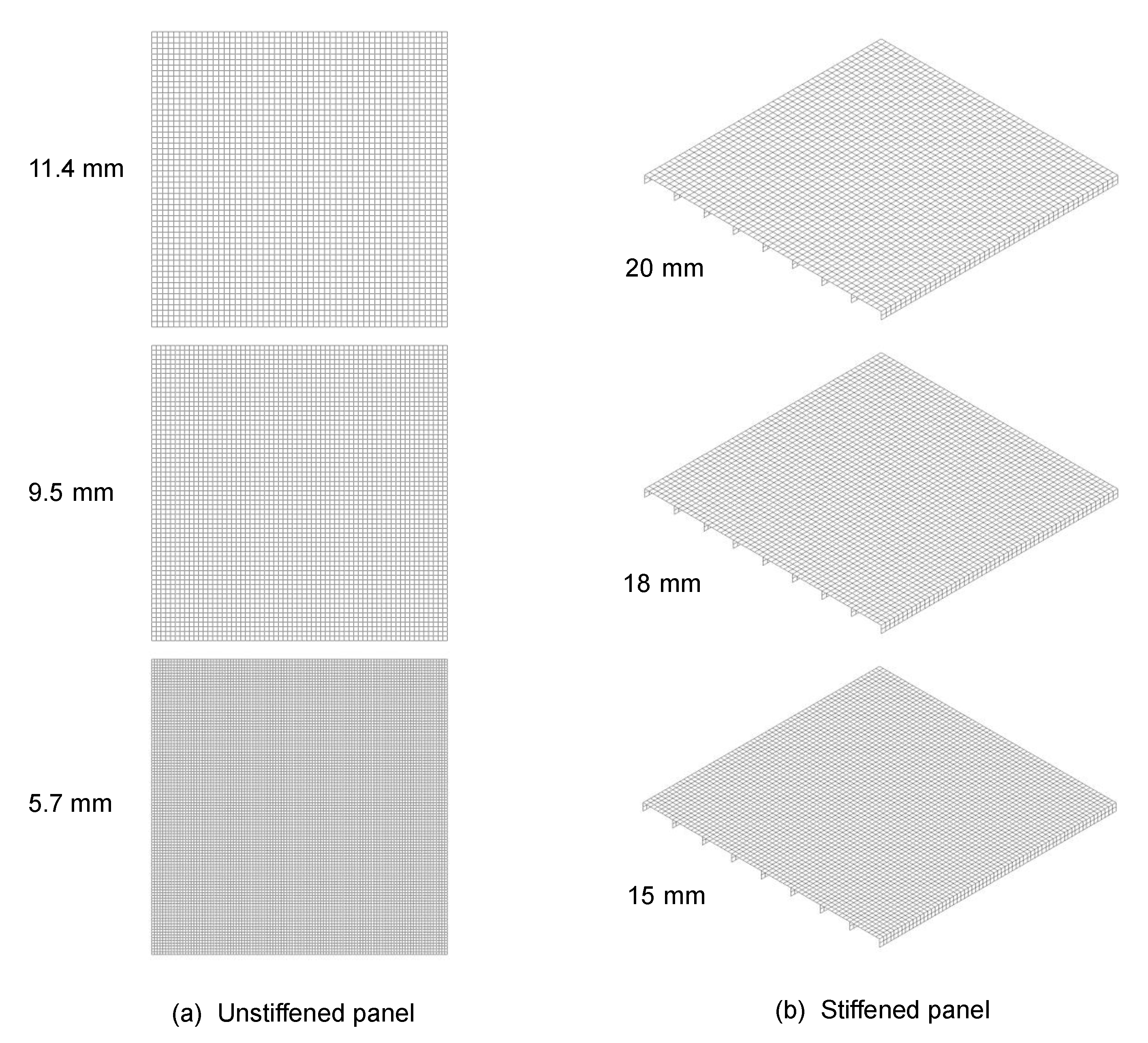
3.2. Numerical Modeling

The numerical simulations were performed while using the software package, Abaqus/ Explicit, and employing the developed VUMAT subroutines for the BWH and BWH-E models. Figure 4 presents the strain hardening curves and localized necking loci. The unclamped parts of the unstiffened and stiffened panels were modeled and meshed with four-node reduced integration shell elements (S4R in the Abaqus element library). Five through-thickness integration points and default hour-glassing control options were applied.
A uniform mesh with different element edge lengths (mesh size) was considered for both of the models. The unstiffened panel model was meshed with 11.4, 9.5, and 5.7 mm elements, whereas the stiffened panel model was meshed with 20, 18, and 15 mm elements. The selected mesh sizes were in accordance with the assumption that the element size should be in the order of multiples of the shell thickness (3–6 t) if localized necking is used as a failure condition for shell elements. Note that the shell thickness is mostly comparable to the size of the through-thickness neck. Similarly, a mesh size of 5–7 times the plate thickness (100–150 mm of typical side shell plates) would be appropriate when applying the model to actual ship structures. The boundaries of the stiffened panels were set as fully clamped. Detailed modeling of the clamping setup was not deemed to be necessary, because the numerical force-displacement results with fully clamped edges agreed well with the test results. The punch was modeled with rigid elements. Figure 5 shows the finite element models of the panels with different mesh sizes.
The contact between the punch and panels was modeled with the general contact algorithm in Abaqus/Explicit. The tangential contact behavior of the polished steel surfaces was modeled while using a friction coefficient of 0.17 and a penalty-type formulation. Numerical tangential contact forces develop during the interaction to exceed the shear capacity of the materials in contact, requiring that some limits be placed on the maximum tangential shear contact force. Therefore, an upper bound estimate of the critical shear stress was set to σ 0 / 3 . Note that the selected friction coefficient and limit on the critical shear stress yielded the best agreement with the test results. The punch was forced to penetrate the stiffened panel at a constant rate. The total simulation duration was kept sufficiently long in order to ensure that the inertial effects were negligible.

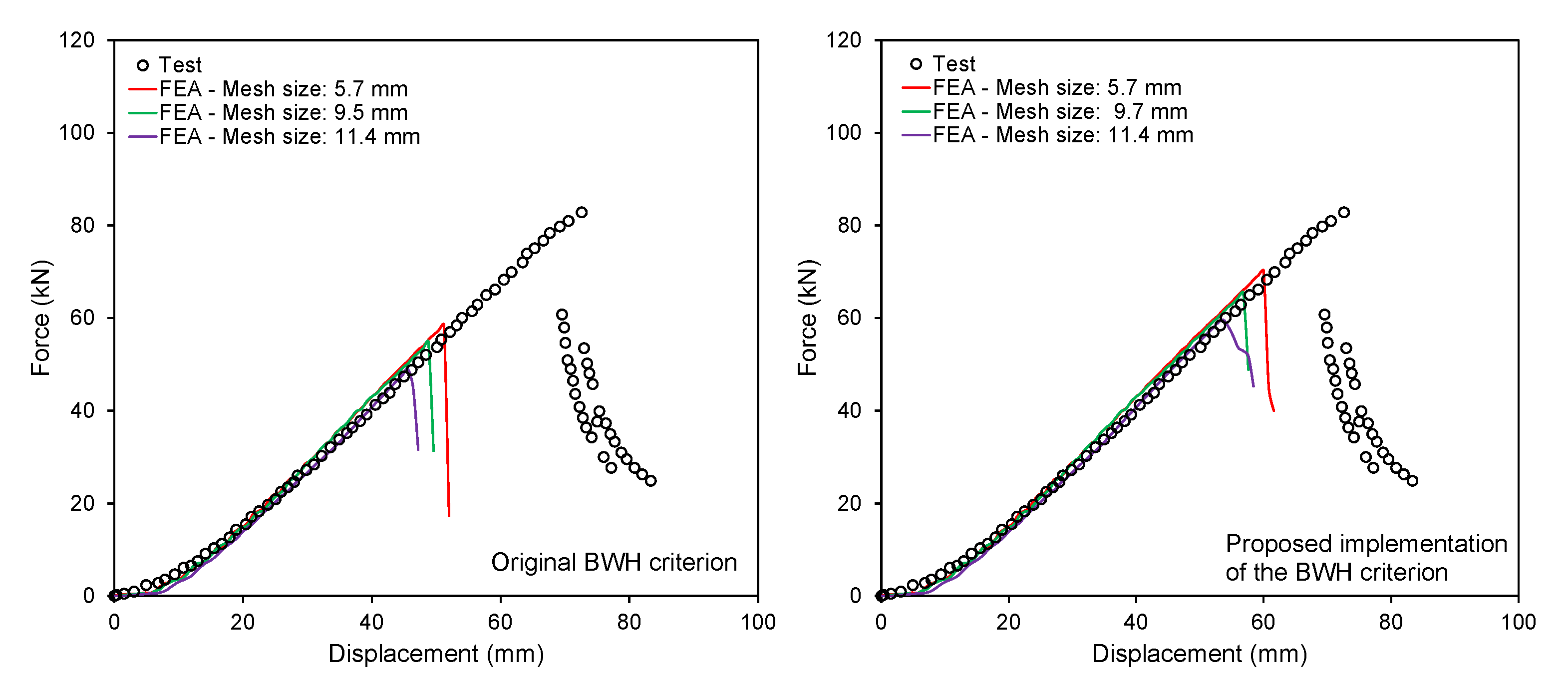
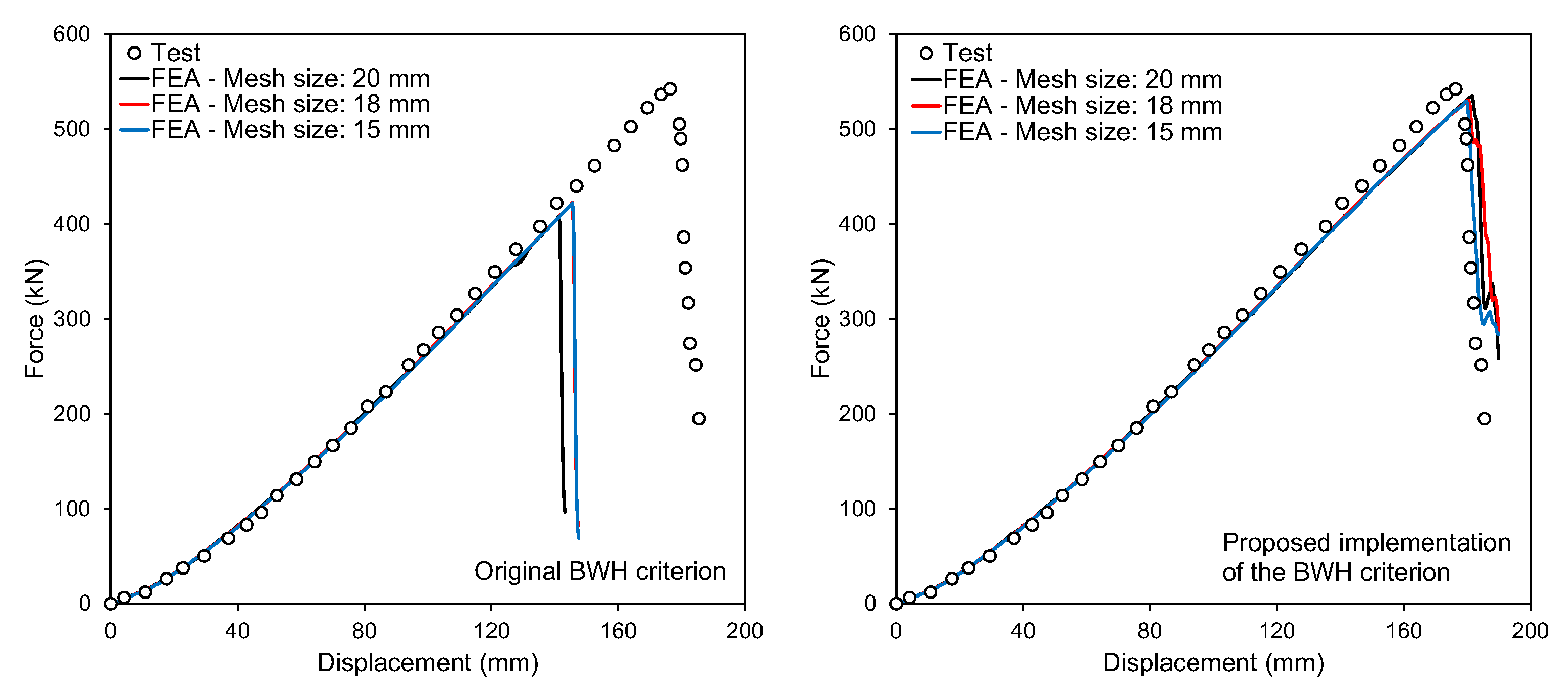
4. Results and Discussion

Figure 6 and Figure 7 compare the test results with the numerical predictions based on the force-displacement curves. Here, the displacement corresponds to the displacement of the punch. The sudden decrease in force indicates fracture initiation. In both cases, regardless of the density of the finite element discretization, the original BWH criterion predictions of fracture initiation were conservative when compared to the proposed numerical implementation of the BWH criterion. Although the BWH-E predictions for the stiffened panel failure were in good agreement with the test result, the predictions for the unstiffened panel failure were conservative. The punch geometry was deemed to be related to the prediction accuracy of fracture initiation using a localized necking criterion as a failure model for the shell elements. The mesh size sensitivity of both models was relatively insignificant only in the case of a stiffened panel loaded with a hemispherical punch. Hence, the mesh size effect is also related to the punch geometry. We should note that, when using the localized necking criterion as a failure model for shell elements, further refining the mesh does not improve the prediction accuracy. The accuracy is lost if the mesh size becomes close to the shell elements thickness.
The observed differences between the proposed and original implementation of the BWH criterion can be attributed to the definition of the failure condition. Figure 8 presents the loading paths that were obtained from the top and bottom layers of the first failed element of the stiffened panel model when using the BWH-E criterion. Furthermore, the loading path of the mid-layer integration point was shown when using the original BWH criterion. Note that the loading paths of the through-thickness integration points are an outcome of the numerical simulations and not directly measurable in the tests. The loading paths were plotted together with the localized necking locus that is defined in the space of stress triaxiality and equivalent plastic strain. In the original BWH criterion, only the final stress state of the through-thickness integration point at the mid-layer, the final stress state, the magnitude of the equivalent plastic strain, and the plastic flow direction in the final step were of concern. Consequently, any change in loading path, i.e., a change in the stress state, which is characterized by η or α , without any accompanying change in the equivalent plastic strain, may also cause immediate failure. This occurs if the loading path direction changes suddenly and crosses the limit curve. Figure 9 presents such an extreme case, where a broken loading path initially in the shear dominated domain crosses the localized necking locus. In this case, although biaxial tension is not experienced, failure will be deemed to have occurred because the final state satisfies the failure condition by crossing the localized necking locus (red dot). In Figure 9, the loading path of the mid-layer (black curve) is non-proportional, i.e., the stress triaxiality is not constant all the way to failure. Localized necking is deemed to have occurred when the loading path of the mid-layer integration point reaches the BWH necking locus, regardless of the loading history of the mid-layer, as well as the integration points of other layers. This is marked with a circle on the graph. On the other hand, the proposed model considers necking as a process and it is associated with the accumulation of plastic strain at all layers of the shell element. In Figure 9, each integration point experiences a different loading path. This was attributed to bending, as mentioned in Section 2.3. The definition of a necking indicator, as given in Equation (15), implies that the history effect is considered. Furthermore, the failure condition is checked in all layers while using Equation (16). Accordingly, although the loading paths of the top and bottom layers cross the localized necking locus, localized necking is significantly delayed when compared to the predictions made using the original BWH criterion.
Another important observation is the differences in the post-fracture response. In the original BWH criterion, the force abruptly decreases once the fracture is initiated on the base plate. In contrast, the proposed model yielded a smoother post-fracture response because the elements are deleted somehow with a certain delay. This can be attributed to the implementation of the necking indicator concept. Figure 10 compares the post-mortem test specimens with the numerically predicted ones. According to [28], fracture has initiated in the face plate of the specimen close to the centerline. After the fracture initiation, the crack has grown gradually parallel to the stiffener, but it was slightly circular. A second branch of crack occurred at the center stiffener, which propagated perpendicularly through the stiffener. Figure 10 shows the final shape of the test specimen, which contains both the main and secondary cracks. In Abaqus, an element is visually deleted from the remainder of the mesh instantly when all through-thickness integration points have zero stresses. Progressively deleting elements simulates fracture propagation, which meet the failure condition that is defined in Section 2. An irregular pattern of deleted elements is apparent in the simulation results with the original BWH criterion. This last point is important for more complex structures, such as the side structure of a ship, where sudden element removal in the side shell plating may lead to overloading and the failure of other structural members, hence an early prediction of rupture in the event of a collision.
The obtained results have several practical implications. It is confirmed that a more refined numerical implementation of localized necking criterion as a shell element failure model has a good predictive capability of fracture initiation in plates, due to punch loading with a relatively round impactor nose. Therefore, it is appropriate for ship collision analysis involving a bulbous bow that is similar to a hemisphere, or stranding analysis involving a smooth and large contact surface. For the prediction of fracture initiation due to an impact with a sharp or blunt impactor, the localized necking model may be combined with a ductile fracture appropriate for predicting shear fracture or surface cracking.

5. Conclusions

Several modifications of the numerical implementation of the well-known BWH criterion for fracture prediction in shell elements were proposed. Although the essence of the localized necking criterion was largely maintained and the proposed modifications were minor, the prediction of the instance of fracture in punch-loaded stiffened panels was considerably improved. Furthermore, a more realistic post-fracture response was simulated with the present model as compared to the original one. These findings show that, in contrast to the common belief on the importance of the mesh size, a prediction of fracture with shell elements is more sensitive to the assumptions that were made in the numerical implementation of failure models within the shell element analysis framework.

Author Contributions

Conceptualization, B.C.C.; methodology, J.C. and B.C.C.; software, B.C.C.; validation, J.C. and B.C.C.; formal analysis, J.C. and B.C.C.; investigation, J.C. and B.C.C.; resources, J.C. and K.L.; data curation, B.C.C.; writing—original draft preparation, B.C.C.; writing—review and editing, J.C., B.C.C. and K.L.; visualization, B.C.C.; supervision, J.C.; project administration, J.C.; funding acquisition, J.C. and K.L. All authors have read and agreed to the published version of the manuscript.

Funding

This work is a result of the principal R&D program, “Core Technology Development of Hydro-Elasticity based Structural Damage Assessment for Offshore Structures Considering Uncertainty [PES3490]” which is supported by KRISO.

Institutional Review Board Statement

Not applicable.

Informed Consent Statement

Not applicable.

Data Availability Statement

No new data were created or analyzed in this study. Data sharing is not applicable to this article.

Conflicts of Interest

The authors declare no conflict of interest. The funders had no role in the design of the study; in the collection, analyses, or interpretation of data; in the writing of the manuscript, or in the decision to publish the results.

Abbreviations

The following abbreviations are used in this manuscript:
BWHBressan-Williams-Hill
BWH-EBressan-Williams-Hill - Extended
FLCForming Limit Curve
FLSDForming Limit Stress Diagram
MSFLDMüschenborn-Sonne Forming Limit Diagram

References

  1. Ringsberg, J.W.; Amdahl, J.; Chen, B.Q.; Cho, S.R.; Ehlers, S.; Hu, Z.; Kubiczek, J.M.; Kõrgesaar, M.; Liu, B.; Marinatos, J.N.; et al. MARSTRUCT benchmark study on nonlinear FE simulation of an experiment of an indenter impact with a ship side-shell structure. Mar. Struct. 2018, 59, 142–157. [Google Scholar] [CrossRef] [Green Version]
  2. Hogström, P.; Ringsberg, J.; Johnson, E. An experimental and numerical study of the effects of length scale and strain state on the necking and fracture behaviours in sheet metals. Int. J. Impact Eng. 2009, 36, 1194–1203. [Google Scholar] [CrossRef] [Green Version]
  3. Marinatos, J.; Samuelides, M. Towards a unified methodology for the simulation of rupture in collision and grounding of ships. Mar. Struct. 2015, 42, 1–32. [Google Scholar] [CrossRef]
  4. Storheim, M.; Amdahl, J.; Martens, I. On the accuracy of fracture estimation in collision analysis of ship and offshore structures. Mar. Struct. 2015, 44, 254–287. [Google Scholar] [CrossRef]
  5. Cerik, B.C.; Park, B.; Park, S.J.; Choung, J. Modeling, testing and calibration of ductile crack formation in grade DH36 ship plates. Mar. Struct. 2019, 66, 27–43. [Google Scholar] [CrossRef]
  6. Park, S.J.; Lee, K.; Cerik, B.C.; Choung, J. Ductile fracture prediction of EH36 grade steel based on Hosford—Coulomb model. Ships Offshore Struct. 2019, 14, 219–230. [Google Scholar] [CrossRef]
  7. Park, S.J.; Cerik, B.C.; Choung, J. Comparative study on ductile fracture prediction of high-tensile strength marine structural steels. Ships Offshore Struct. 2020. [Google Scholar] [CrossRef]
  8. Cerik, B.C.; Choung, J. Ductile fracture behavior of mild and high-tensile strength shipbuilding steels. Appl. Sci. 2020, 10, 7034. [Google Scholar] [CrossRef]
  9. Kõrgesaar, M.; Romanoff, J. Influence of mesh size, stress triaxiality and damage induced softening on ductile fracture of large-scale shell structures. Mar. Struct. 2014, 38, 1–17. [Google Scholar] [CrossRef]
  10. Storheim, M.; Alsos, H.S.; Hopperstad, O.S.; Amdahl, J. A damage-based failure model for coarsely meshed shell structures. Int. J. Impact Eng. 2015, 83, 59–75. [Google Scholar] [CrossRef]
  11. Liu, B.; Villavicencio, R.; Zhang, S.; Guedes Soares, C. A simple criterion to evaluate the rupture of materials in ship collision simulations. Mar. Struct. 2017, 54, 92–111. [Google Scholar] [CrossRef]
  12. Cerik, B.C.; Lee, K.; Park, S.J.; Choung, J. Simulation of ship collision and grounding damage using Hosford-Coulomb fracture model for shell elements. Ocean Eng. 2019, 173, 415–432. [Google Scholar] [CrossRef]
  13. Cerik, B.C.; Choung, J. Rate-dependent combined necking and fracture model for predicting ductile fracture with shell elements at high strain rates. Int. J. Impact Eng. 2020, 146, 103697. [Google Scholar] [CrossRef]
  14. Cerik, B.C.; Park, S.J.; Choung, J. Use of localized necking and fracture as a failure criterion in ship collision analysis. Mar. Struct. 2020, 73, 102787. [Google Scholar] [CrossRef]
  15. Cerik, B.C.; Choung, J. On the prediction of ductile fracture in ship structures with shell elements at low temperatures. Thin-Walled Struct. 2020, 151, 106721. [Google Scholar] [CrossRef]
  16. Cerik, B.C.; Park, S.J.; Choung, J. Predicting ductile fracture in maritime crash with a modified implementation of BWH criterion. Lect. Notes Civ. Eng. 2021, 64, 701–714. [Google Scholar] [CrossRef]
  17. Zhu, L.; Atkins, A.G. Failure criteria for ship collision and grounding. In Proceedings of the Seventh International Symposium on Practical Design of Ships and Mobile Units, The Hague, The Netherlands, 20–25 September 1998; pp. 149–156. [Google Scholar]
  18. Alsos, H.S.; Hopperstad, O.S.; Törnqvist, R.; Amdahl, J. Analytical and numerical analysis of sheet metal instability using a stress based criterion. Int. J. Solids Struct. 2008, 45, 2042–2055. [Google Scholar] [CrossRef] [Green Version]
  19. Cerik, B.C.; Ringsberg, J.W.; Choung, J. Revisiting MARSTRUCT benchmark study on side-shell collision with a combined localized necking and stress-state dependent ductile fracture model. Ocean Eng. 2019, 187, 106173. [Google Scholar] [CrossRef]
  20. Mattiasson, K.; Jergéus, J.; DuBois, P. On the prediction of failure in metal sheets with special reference to strain path dependence. Int. J. Mech. Sci. 2014, 88, 175–191. [Google Scholar] [CrossRef]
  21. Swift, H. Plastic instability under plane stress. J. Mech. Phys. Solids 1952, 1, 1–18. [Google Scholar] [CrossRef]
  22. Stoughton, T.B. Stress-based forming limits in sheet-metal forming. J. Eng. Mater. Technol. 2001, 123, 417. [Google Scholar] [CrossRef]
  23. Stoughton, T.B.; Zhu, X. Review of theoretical models of the strain-based FLD and their relevance to the stress-based FLD. Int. J. Plast. 2004, 20, 1463–1486. [Google Scholar] [CrossRef]
  24. Bai, Y.; Wierzbicki, T. Forming severity concept for predicting sheet necking under complex loading histories. Int. J. Mech. Sci. 2008, 50, 1012–1022. [Google Scholar] [CrossRef]
  25. Stoughton, T.B.; Yoon, J.W. A new approach for failure criterion for sheet metals. Int. J. Plast. 2011, 27, 440–459. [Google Scholar] [CrossRef]
  26. Li, Y.; Luo, M.; Gerlach, J.; Wierzbicki, T. Prediction of shear-induced fracture in sheet metal forming. J. Mater. Process Technol. 2010, 210, 1858–1869. [Google Scholar] [CrossRef]
  27. Park, S.J.; Choung, J. Punching fracture experiments and simulations of unstiffened and stiffened panels for ships and offshore structures. J. Ocean Eng. Technol. 2020. [Google Scholar] [CrossRef]
  28. Kõrgesaar, M.; Romanoff, J.; Remes, H.; Palokangas, P. Experimental and numerical penetration response of laser-welded stiffened panels. Int. J. Impact Eng. 2018, 114, 78–92. [Google Scholar] [CrossRef]
Figure 1. Bressan–Williams–Hill (BWH) criterion expressed in different variable spaces.
Jmse 09 00117 g001
Figure 2. Illustration of possible loading cases and evaluating the occurrence of through-thickness necking with shell elements.
Jmse 09 00117 g002
Figure 3. Punching test setup and post mortem unstiffened panel.
Jmse 09 00117 g003
Figure 4. Hardening and forming limit curves of the panel materials.
Jmse 09 00117 g004
Figure 5. Applied mesh on (a) unstiffened panel and (b) stiffened panel.
Jmse 09 00117 g005
Figure 6. Comparison of numerical analysis predictions with the test results of unstiffened panels.
Jmse 09 00117 g006
Figure 7. Comparison of numerical analysis predictions with the test results of stiffened panel.
Jmse 09 00117 g007
Figure 8. Loading paths observed in the through-thickness integration points of the first failed element in the stiffened panel model.
Jmse 09 00117 g008
Figure 9. Failure check using the original BWH criterion for the case of a broken loading path initially in shear-dominated stress state.
Jmse 09 00117 g009
Figure 10. Comparison of experimental and numerically predicted post-fracture shapes of the tested stiffened panel.
Jmse 09 00117 g010
Publisher’s Note: MDPI stays neutral with regard to jurisdictional claims in published maps and institutional affiliations.

