Article

Pilot-Assisted OFDM for Underwater Acoustic Communication

1
Institute of Oceanic Engineering Research, University of Malaga, 29071 Malaga, Spain
2
Telecommunication Engineering School, University of Malaga, 29071 Malaga, Spain
3
Department of Computer Engineering, Umm Al-Qura University, Makkah 21955, Saudi Arabia
*
Author to whom correspondence should be addressed.
J. Mar. Sci. Eng. 2021, 9(12), 1382; https://doi.org/10.3390/jmse9121382
Submission received: 28 October 2021 / Revised: 24 November 2021 / Accepted: 30 November 2021 / Published: 4 December 2021
(This article belongs to the Section Ocean Engineering)

Abstract

:
Multicarrier techniques have made it possible to wirelessly transmit data at higher rates for underwater acoustic (UWA) communication. Several multicarrier techniques have been explored in the past for wireless data transmission. OFDM is known to fight off inter-symbol interference due to the orthogonality of its subcarriers. However, due to time variations, OFDM suffers from intercarrier interference. As the UWA channel is both a time and frequency variant, channel estimation becomes complex. We propose a pilot-based channel estimation technique and explore two equalizers for improving the error performance of an OFDM-based UWA system. Both the equalizers employ pilot subcarriers to estimate the UWA channel. One equalizer is a least squares (LS) equalizer and the other is a zero forcing (ZF) equalizer. Using computer simulations, it is observed that, for an acceptable error performance, the number of pilots should be one-fourth the number of subcarriers. Moreover, if the energy of the pilots is increased without changing the overall symbol energy, the error performance degrades. It is also noted that both the LS and ZF equalizers give an acceptable error performance with the ZF performing marginally better than the LS. Furthermore, the error performance of the proposed system is evaluated as a function of the transmitter-receiver distance and an acceptable error performance is observed even at 1250 m.

1. Introduction

The UWA channel is doubly selective due to multipath fading and a Doppler shift [1]. When compared with radio waves, acoustic waves have lower speeds and the bandwidth is higher when compared with the carrier [2]. The channel is a time variant as Doppler shifts are induced due to the relative motion of the transmitter and receiver [3]. Furthermore, the underwater acoustic channel is wideband and, as fewer path components carry most of the energy, the channel is sparce.
Among the multicarrier modulation schemes, OFDM has been shown to be effective against inter-symbol interference (ISI) because of its longer symbol duration. Due to the motion of transmitting and receiving nodes in a UWA channel, OFDM is prone to frequency offsets [3]. OFDM works by splitting the frequency selective channel into several flat fading channels. Moreover, an OFDM symbol contains a cyclic prefix (CP) whose length is kept equal to or greater than the delay spread of the channel to combat ISI [4]. When using OFDM in a UWA channel, the subcarrier spacing must be reduced as the bandwidth of the UWA channel is significantly small. However, this introduces ICI [5,6].
Almost all OFDM receivers use a channel estimation technique to compute approximate values of the channel parameters. Several types of estimation techniques have been explored in the literature to accurately estimate the channel for OFDM. These include blind, semi-blind, and pilot-based channel estimation techniques. Out of these techniques, the pilot-based technique is widely used mainly because of the ease in its implementation along with a better performance. The downside of this technique is the bandwidth overhead, resulting in poor spectral efficiency [7,8,9]. For UWA channels, this type of technique is preferable because the underwater nodes have limited power and limited processing capabilities. In a typical pilot-based channel estimation scheme, a few known symbols—also called training symbols—are inserted into the transmitted OFDM symbols at prespecified locations. These known symbols are then extracted by the receiver and are used for the synchronization and determination of the channel parameters [10]. Several estimation techniques have been used with OFDM receivers such as maximum likelihood (ML), minimum mean square error (MMSE) estimation, and least squares error (LSE) estimation.
With the rise in data rates in future UWA systems, the symbol duration will keep on decreasing with the increasing data rates making the equalization process complex [11]. As OFDM offers a higher data rate and one-tap equalization, it is an ideal candidate for UWA communication systems. Moreover, as the equalization is performed in the frequency domain, the fast Fourier transform (FFT) in the receiver of the OFDM further reduces the equalization complexity [12]. However, coping with Doppler shifts is a challenge as they affect the orthogonality of the subcarriers due to phase variations. Hence, the problem of equalization when using OFDM in UWA channels has been addressed and several solutions have been proposed in the literature. In radio-based systems, zero forcing equalizers have been used as they are simple to implement. However, they suffer from significant noise amplification near to the zeroes of the channel in an attempt to invert the channel completely. MMSE equalizers overcome the shortcomings of ZF equalizers at the cost of complexity.
This paper adds to the body of research in two ways. We propose the investigation of a channel estimation algorithm based upon a least squares error estimation. This algorithm is applied to a typical OFDM system, in which pilot signals are used for a UWA channel. In this algorithm, the pilot signals are inserted at predefined subcarriers and the receiver estimates the channel using the LSE algorithm. Secondly, we compare LSE and ZF equalizers. Based upon the channel delay spread, we tune the position and number of pilots as well as vary the length of the cyclic prefix to improve performance. Using a Monte Carlo simulation, we provide several bit error rate (BER) plots to show the performances of the equalizers as a function of the various parameters. These simulations are performed over a UWA channel that uses a Rician fading distribution and incorporates absorption loss and ambient noise.
The paper is organized as follows. Section 2 of the paper details the background and state of the art research. Section 3 explains the OFDM system architecture along with the channel estimator and equalizer. The channel model is detailed in Section 4. Section 5 presents the results from the simulations and provides a discussion on the reported results. The paper is concluded in Section 6 along with future enhancements.

2. State of the Art Research

This section highlights the recent work undertaken in areas of pilot-based channel estimation and equalization in the domain of UWA.

2.1. Pilot-Based Channel Estimation

In the wireless domain, pilot-based estimation has long been used with multicarrier systems such as OFDM. In the UWA channels, several estimation algorithms have also been proposed when using OFDM systems. In the following, we present an overview of the work recently undertaken in this domain, mainly for UWA channels.
An adaptive channel estimation technique was proposed in [13] for a MIMO-OFDM system. In this work, a least squares estimation algorithm was used along with a block-adaptive method. This had the additional advantage of avoiding the computational complexity of a matrix inversion. The accuracy of the proposed algorithm depended upon its ability to determine the channel parameters from the pilot estimates of the previous block. An algorithm that inserted multiple pilots in an OFDM system to estimate the UWA channel was investigated in [14]. The authors employed three types of pilots, namely, comb, block, and scatter. It was shown that the scatter type of pilots gave the best performance in terms of robustness against the time selectivity and frequency selectivity of the channel. In [15], a deep neural network (DNN) was trained on estimated pilot symbols. The trained network was then used to estimate the impulse response of the underwater channel. A simulation testbed that used OFDM for a UWA communication system was presented by Wang et al. [16]. The results were reported for two channel estimation techniques, namely, LSE and MMSE. A channel estimation scheme designed for radio frequency CP-OFDM that used LSE was presented in [17]. The authors also compared the estimated channel with a real channel. Using pilots for an adaptive estimation of the UWA channel, a recursive least squares algorithm was proposed in [18] to estimate the channel for a MIMO-OFDM system. Moreover, a maximum likelihood decoder was employed to estimate the transmitted data. In another publication [19], the authors used multiple channel sensing and estimation techniques to capture the time-varying behavior of a UWA channel.

2.2. Linear Equalization

One of the advantages of OFDM is that it simplifies the equalization in the frequency domain. The literature is full of equalization techniques for OFDM. A few are covered in this section. In [12], the authors proposed a zero-padded OFDM that used a mean square error combining technique to estimate the transmitted data after obtaining the channel estimates. A high data rate acoustic modem for coherent OFDM was proposed by Sean et al. [11]. In this work, the received signal was equalized using a scalar inversion of the channel estimates. Using a decision feedback equalizer along with time reversal was employed for an OFDM system over a UWA channel by Gomes et al. [20]. When comparing the computational complexity of the proposed equalizer, it was of the same order as that of a single carrier system. In [21], it was argued that as zero forcing equalizers have a tendency to enhance noise, they should not be used for a UWA OFDM system. They also argued that a minimum mean square error equalizer is not only complex but it also needs an estimate of the SNR. Consequently, the authors proposed a low complexity zero forcing equalizer that addressed these concerns. In another work [22], a combination of matching pursuit and maximum a posteriori algorithms was used to estimate a UWA channel. The authors also employed a linear minimum mean square equalizer at the receiver. An iterative least squares equalizer was proposed in [23] and its performance was compared with a conventional frequency domain equalizer. In [24], a channel was divided into several sub-bands. Each sub-band was treated as a narrowband channel. A minimum mean square error equalizer was employed with soft information. The complexity was reduced by exploiting the narrowband sub-bands. An equalizer that had a single tap and used a least mean square algorithm was reported in [25]. The proposed equalizer was also compared with a mean square error equalizer implemented in an OFDM system over a UWA channel. In [26], turbo equalization was used in field experiments performed in shallow water. The trials were conducted for three months with a negligible Doppler but a variable multipath channel. It was shown that turbo equalization with a 4-PSK modulation outperformed a decision feedback equalizer.

3. System Architecture

This section presents the architectures of OFDM transceivers and the two proposed systems.

3.1. Pilot-Based Channel Estimation

A typical OFDM transceiver in a UWA channel is presented in the first subsection. A detailed description of the least squares channel estimator is given in the second subsection.

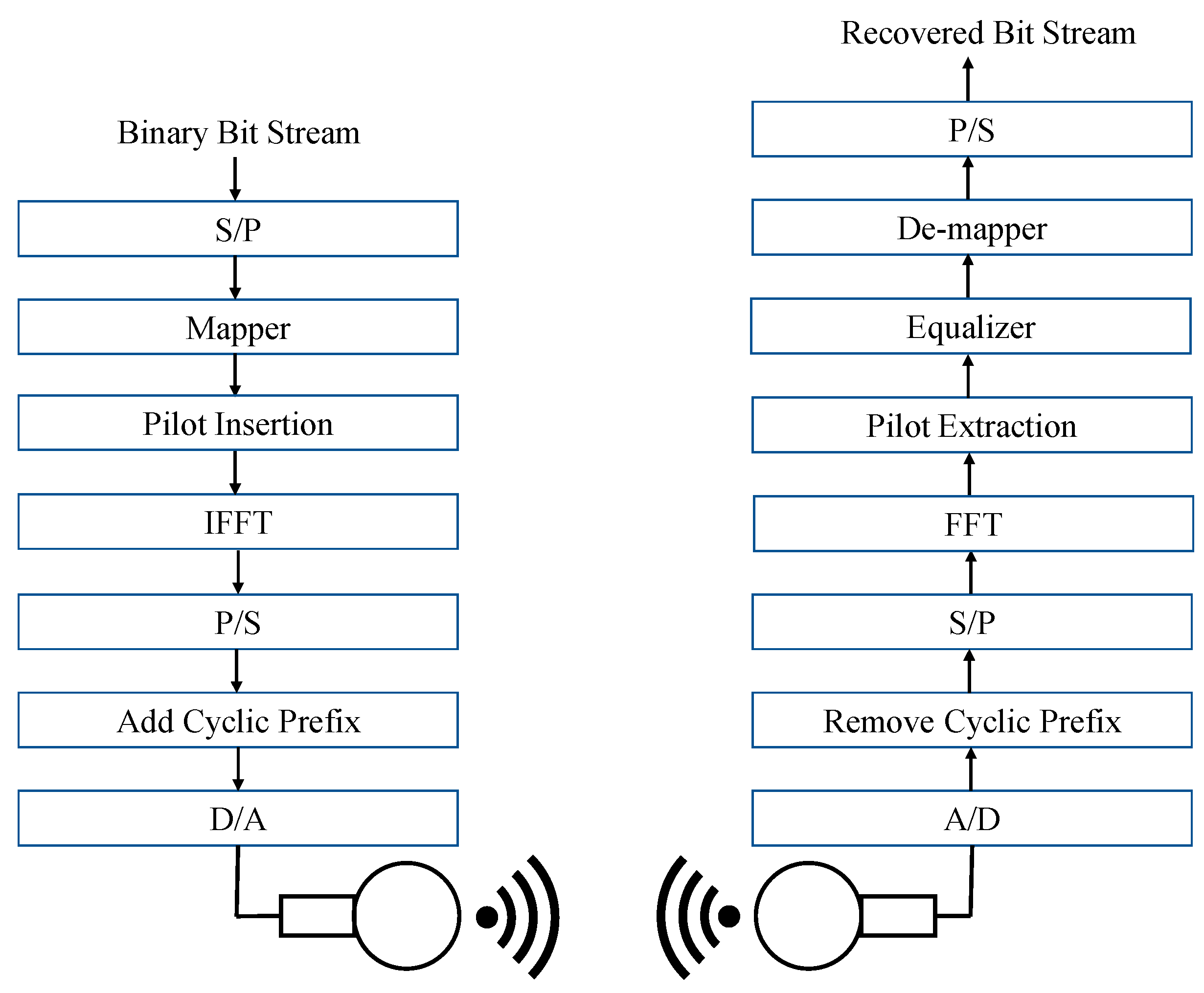
3.1.1. OFDM Transceiver

A typical CP-OFDM transceiver model working in a UWA channel is shown in Figure 1. Let B represent the vector of a serial binary bit stream where each element of B is either a binary 0 or 1. This binary stream is fed into the OFDM transmitter. A serial to parallel converter, represented by S/P in the figure, converts the serial stream into a parallel stream that has N symbols where N is the number of subcarriers.
Each parallel stream of N samples makes one OFDM symbol where each element of N consists of log 2 M bits. M is the modulation order to be used in the next block, i.e., the mapper. For example, if the mapper is BPSK, each symbol at the output of the S/P block will have only one bit. On the other hand, if the mapper is QPSK, each symbol will consist of two bits. The parallel stream of N symbols then passes through the mapper and is converted into complex numbers based upon the type of mapper used. Let these complex numbers be represented by a vector C k where k is the k th OFDM symbol and each element of the vector C k is a complex number. Mathematically, this can be shown as:
C k = [ c k , 0 ,   c k , 1 ,   c k , 2 , ..... c k , N 1 ] T .
In the proposed OFDM system, pilots are inserted at predetermined intervals into each OFDM symbol. This is achieved by using certain subcarriers as pilots. Further details of these pilots will be described later in the paper. The parallel stream of complex numbers then passes through the inverse fast Fourier transform (IFFT) that transforms the complex numbers into another set of complex numbers that are orthogonal to each other. Let this new stream of complex numbers be represented by X k , which can be shown mathematically as:
X k = [ x k , 0 , x k , 1 ,   .   .   .   ,   x k , N 1 ] T .
The P/S block then converts the parallel stream of complex numbers into a serial stream. To combat the effects of a multipath, a cyclic prefix—denoted by CP—is appended to each OFDM symbol before it is converted into an analog signal for the final transmission. If T represents the duration of the OFDM symbol and f p the frequency of the p th subcarrier, then the transmitted signal can mathematically be expressed as:
x k ( t ) = 1 / T p = 0 N 1 c k , p e j 2 π f p t .
In this equation, T is a scaling factor. After passing through the UWA channel, the signal is processed by the receiver in reverse order, as shown in Figure 1. Let x ^ ( t ) be the received signal that is a noisy and distorted version of the transmitted signal. This signal is converted into a digital signal by the A/D block. In the next step, the cyclic prefix is removed. The S/P block coverts the serial stream into parallel streams of N symbols and the fast Fourier transform (FFT) is applied to each parallel stream. As the signal has been distorted by the UWA channel and noise has been added to it, the complex numbers at the output of the FFT can mathematically be represented as:
C ^ k = H k C k + n k .
In the above equation, C ^ k is a vector that represents the noisy and distorted version of the transmitted vector C k . H k is the channel transfer function affecting the k th OFDM symbol and n k is the additive white Gaussian noise affecting the k th OFDM symbol. The pilots are extracted next and used by the equalizer to neutralize the effects of the UWA channel and estimate the transmitted complex numbers. The de-mapper block coverts the estimated OFDM symbol of complex numbers into digital data and the P/S block converts the parallel stream of digital data into a serial stream.

3.1.2. Least Squares Channel Estimation

In this work, we used the pilot-based channel estimation approach proposed by Cai et al. [27]. Originally, the approach was used for a single input multiple output (SIMO) OFDM system. We applied the same approach for a single input single output (SISO) OFDM for a shallow UWA channel-based model on a Rician distribution, explained in Section 4. In this approach, the channel estimates were obtained via pilots and then maximum ratio combining (MRC) was used to estimate the transmitted data.
Consider the OFDM system of Figure 1. Let:
-
I p be the set of those subcarriers that carry the pilots;
-
y [ n ] be the signal on n th subcarrier after the extraction of pilots;
-
s n be the pilot symbol with n   ϵ   I p ;
-
H k , n be the channel transfer function for n th subcarrier of the k th OFDM symbol;
-
ω n be the AWGN on the n th subcarrier;
-
p be the transmit power of the pilot symbol.
The signal y [ n ] is then given by:
y [ n ] = p H k , n s n + ω n ,   n I p .
Let h = [ h 0 , , h L 1 ] T represent a vector of the impulse response of a Rician channel where each element of the vector is a complex Gaussian variable with a zero mean and L represents the number of taps. Consider a matrix F having L × N dimensions where N represents the number of subcarriers in the OFDM system. Each element of matrix F is defined as:
[ F ] l , n : = e ( j 2 π ( l 1 ) ( n 1 ) N ) .
Let F p : = [ f n 1 , , f n P ] where f n i is the n th column of F . Define G as:
G : = ( p F p D ( s p ) D ( s p ) F p ) 1 ( p D ( s p ) F p ) .
In this equation, D ( s p ) is a diagonal matrix, s p are the pilots in a diagonal, and represents the Hermitian. If the estimated channel impulse response is h ^ , obtained by using LSE, then:
h ^ = Gy = h + η
with η = G ω [28]. Finally, the estimate of the channel transfer function for the k th OFDM symbol and the n th subcarrier—denoted by H ^ k , n —is given by:
H ^ k , n = f n h ^ .

3.2. Linear Equalization

The fact that equalization can be done in the frequency domain makes OFDM an attractive choice for radio as well as UWA channels. In this work, two linear equalizers that operated in the frequency domain were evaluated. The performance of both equalizers was compared in terms of the BERs that they offered over a shallow UWA channel. For one equalizer, the channel was estimated using pilots and an LS estimator. For the other, it was assumed that perfect channel estimates were available and the ZF equalizer was used to estimate the transmitted sequence.

3.2.1. Least Squares (LS)

This is an LSE-based estimator. It uses one-fourth of the number of subcarriers in the OFDM system. If C ^ k represents the vector of the estimated sequence and H k represents the estimated channel transfer function in the frequency domain, then the equalized sequence C ˜ k is given by:
C ˜ k = C ^ k | H k | .

3.2.2. Zero Forcing (ZF)

Assuming a perfect knowledge of the channel in terms of H k , i.e., the channel transfer function for the k th OFDM symbol, the equalized sequence C ˜ k is given by:
C ˜ k = H k * | H k | 2   C ^ k = C k + H k * | H k | 2   n k .
In this equation, n k represents the AWGN added to the k th OFDM symbol and * represents the conjugate.

4. Shallow Underwater Acoustic Channel Model

An underwater channel is doubly selective in nature as the signals undergo both frequency and time selectivity [1,29]. Over longer distances, the bandwidth is limited (a few kilohertz), restricting intercarrier spacing and thus making the system sensitive to even smaller Doppler shifts [5,30]. Motion induced attenuation is significant because the speed of sound is much less compared with RF waves [3]. For time shifted L multipath components [1], the response can mathematically be represented as:
H ( t , τ ) = p = 1 L A p ( t ) δ ( τ τ p ( t ) )
where A p represents the amplitude of the p t h multipath component, τ p denotes the delay coefficient, and δ indicates the Dirac delta function. The effect of Doppler frequency shifts differ for different subcarriers because the bandwidth and center frequency are comparable. The envelop channel response consists of random multipath fading and deterministic responses.
Figure 2 features the modulated time domain signal s ( t ) from Equation (3) passing through several channel blocks. The elaborated system enabled the tuning of various parameters including the channel taps, absorption-related path loss from Thorp’s formula [31], and the SNR. For a shallow underwater acoustic channel, the delay spread is usually between 10   to   20   ms and can be up to 100   m s [32].

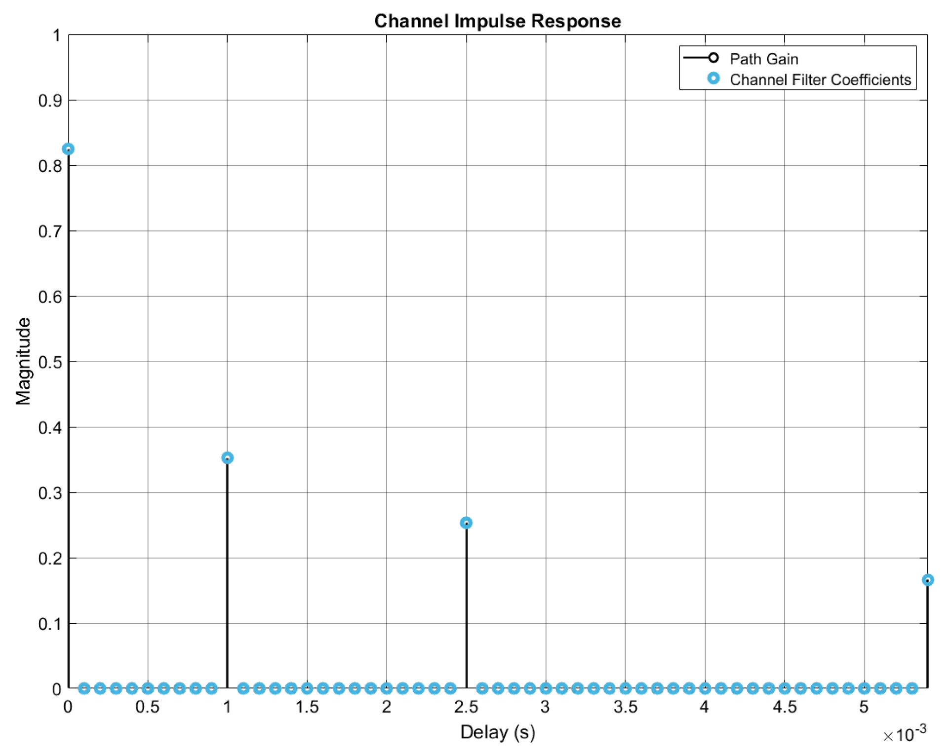
4.1. Deterministic Response

The energy of an acoustic signal attenuates both with respect to distance as well as a function of the frequency. The path loss thus combines both geometric spreading and absorption. If the time variation is represented as e j ω t , the expression for the frequency domain transmission loss in a positive z direction is mathematically expressed as:
E ( z ) = E 0   e γ z = E 0   e α z   e j β z
where E 0   denotes the scaling constant. The deterministic transfer function H a ( f , d ) [33,34] becomes:
H a ( f , d ) = A d   e γ ( f ) d
where A d is the scaling constant, d is the distance between the transmitter and receiver, and γ represents the propagation constant in m 1 :
γ ( f ) = α ( f ) + j β ( f )
where α ( f ) and β ( f ) are the absorption and phase constants, respectively. The Thorp formula [31] expresses the absorption coefficient in dB / km as:
α d B ( f ) = 1 . 094 ( 0 . 003 + 0 . 1 f 2 1 + f 2 + 40 f 2 4100 + f 2 + 0 . 000275 f 2 ) .
The phase constant in rad / m is expressed as:
β ( f ) = 2 π f c s
where c s represents the sound velocity in m s 1 and is computed using Medwin’s equation [35]. The signal c 1 ( t ) in Figure 2 was computed through convolution as:
c 1 ( t ) = h a ( t , d )     s ( t )
where h a ( t , d ) is the IFFT of the channel transfer function.

4.2. Random Channel

Various experimental studies suggest that fading in a shallow UWA channel is more accurately represented using a Rician fading model [36]. Researchers in [37,38] studied sea trial data from several experiments where the Rician shadowed distribution was found to have the closest fit. In this work, the parameters used were m = 0.4 and k = 2.0 [38]. The signal c 2 ( t ) was computed as:
c 2 ( t ) = h r ( t )     c 1 ( t ) + n ( t )
where n ( t ) and h r ( t ) are the ambient noise and the Rician fading impulse response [39,40] modelled together with the Doppler shift using the Rician object in MathWorks MATLAB R2019. Figure 3 represents the sample delay profile and path gains.

4.3. Ambient Noise

The noise in a shallow underwater acoustic channel is location specific, frequency dependent, and cannot be modelled as white noise. For the simulations, an ambient noise model combining thermal, shipping, wave, and turbulence noise [41] was incorporated. The power spectral density (PSD) was computed as:
N ( f ) = 10 log ( 10 N s h i p p i n g ( f ) 10 + 10 N t u r b u l a n c e ( f ) 10 + 10 N w a v e ( f ) 10 + 10 N t h e r m a l ( f ) 10 ) .
It could be modelled as colored noise and had a high amplitude around the lower and higher end of the acoustic communication spectrum and was the lowest at around 60 kHz [42].

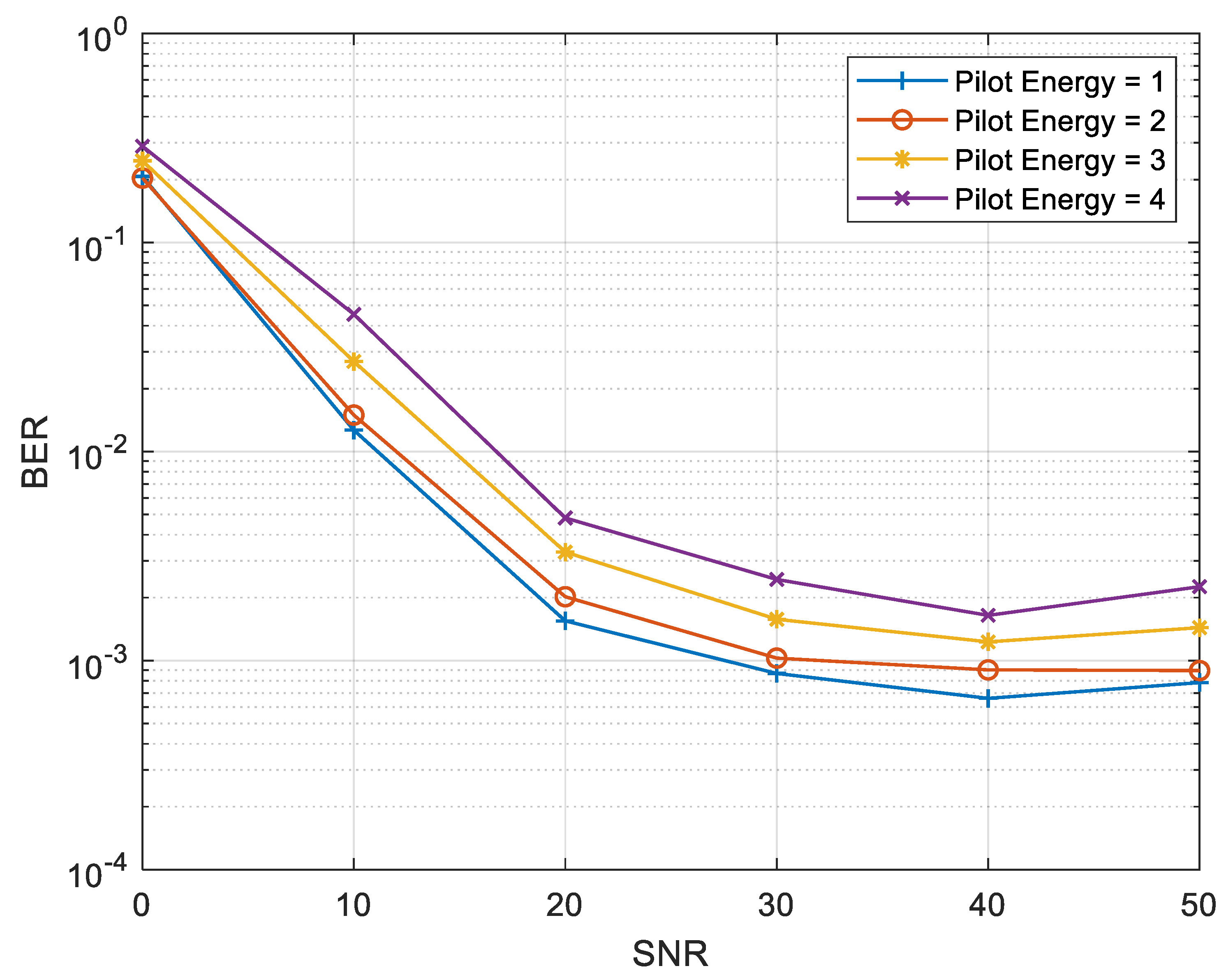
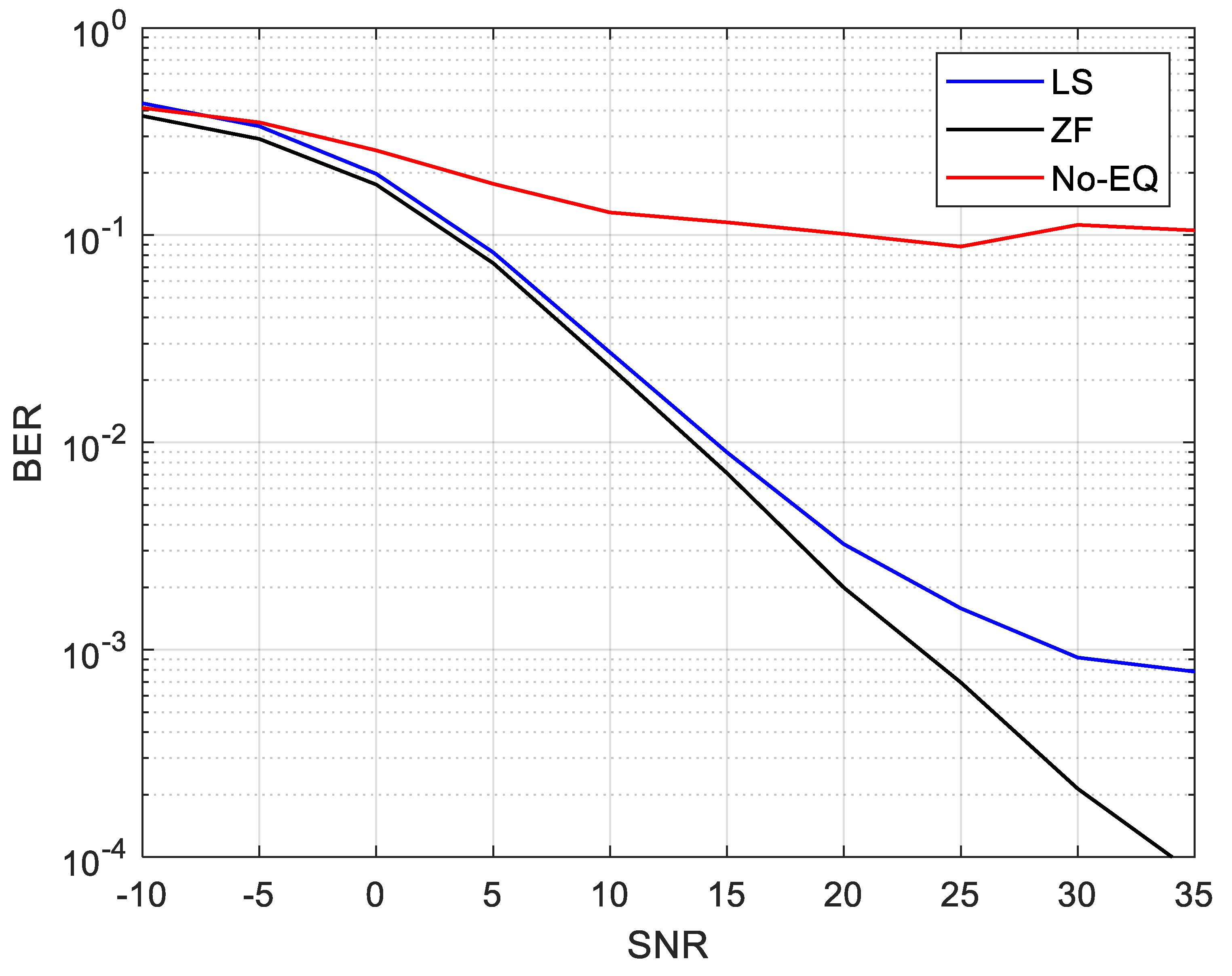
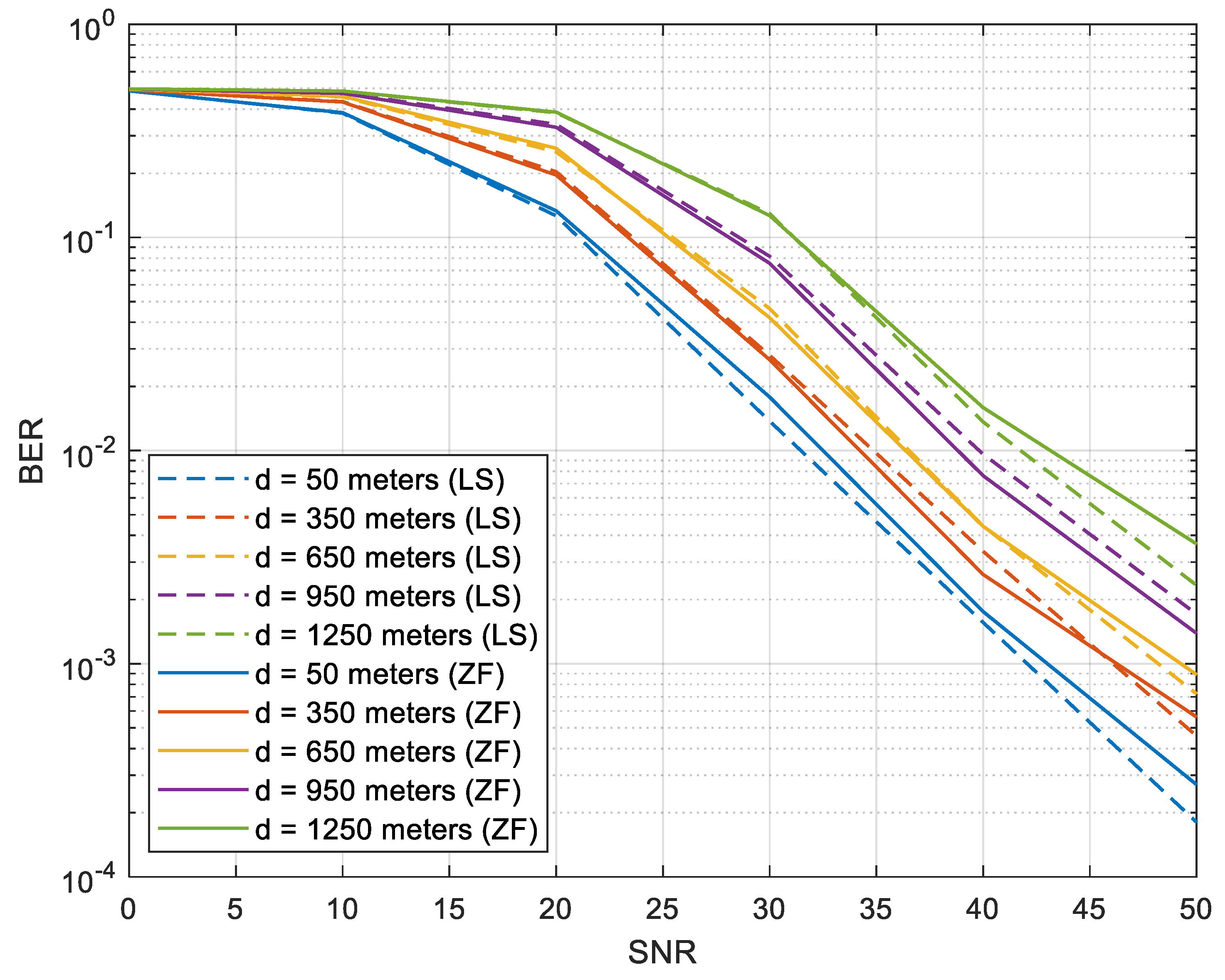
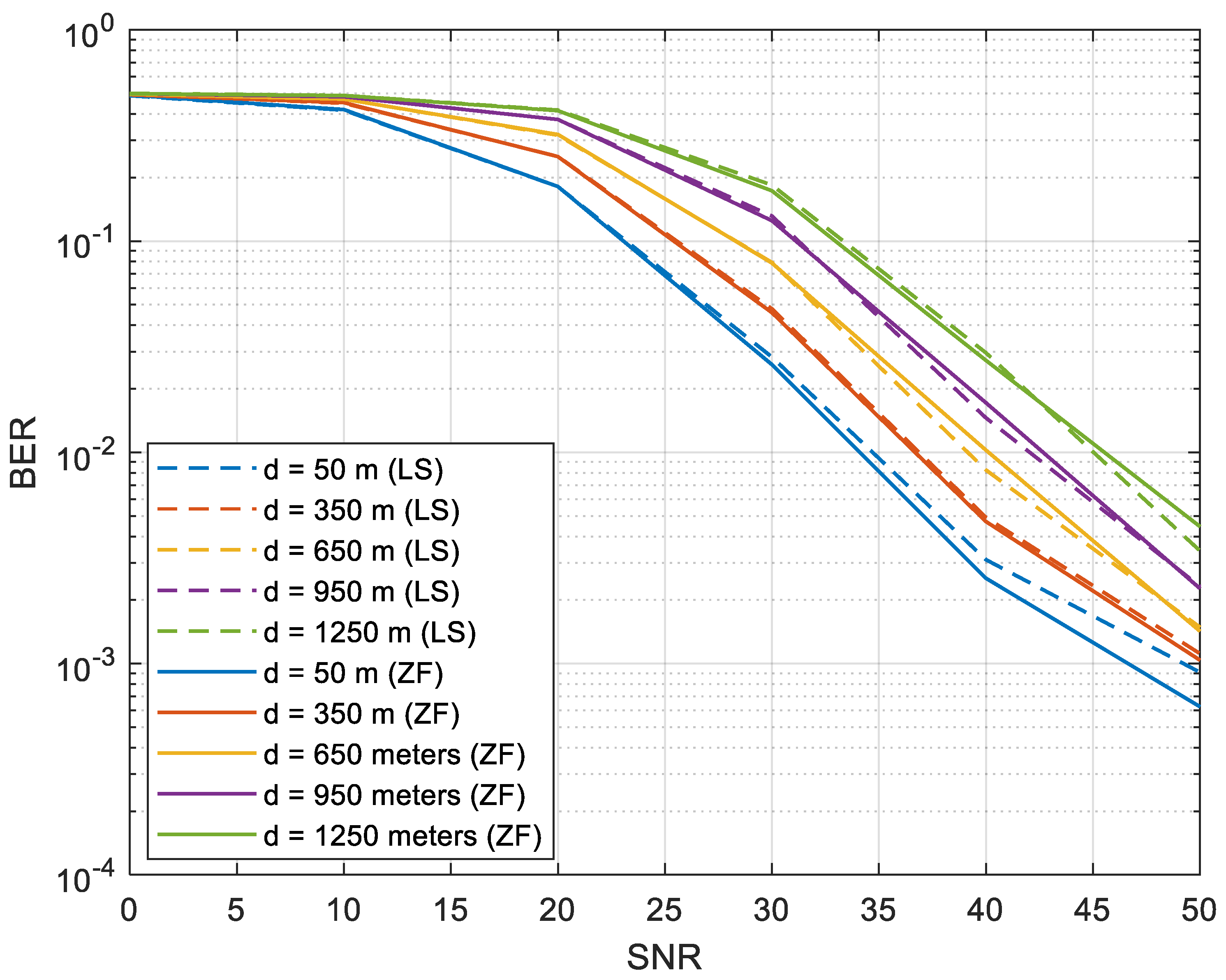
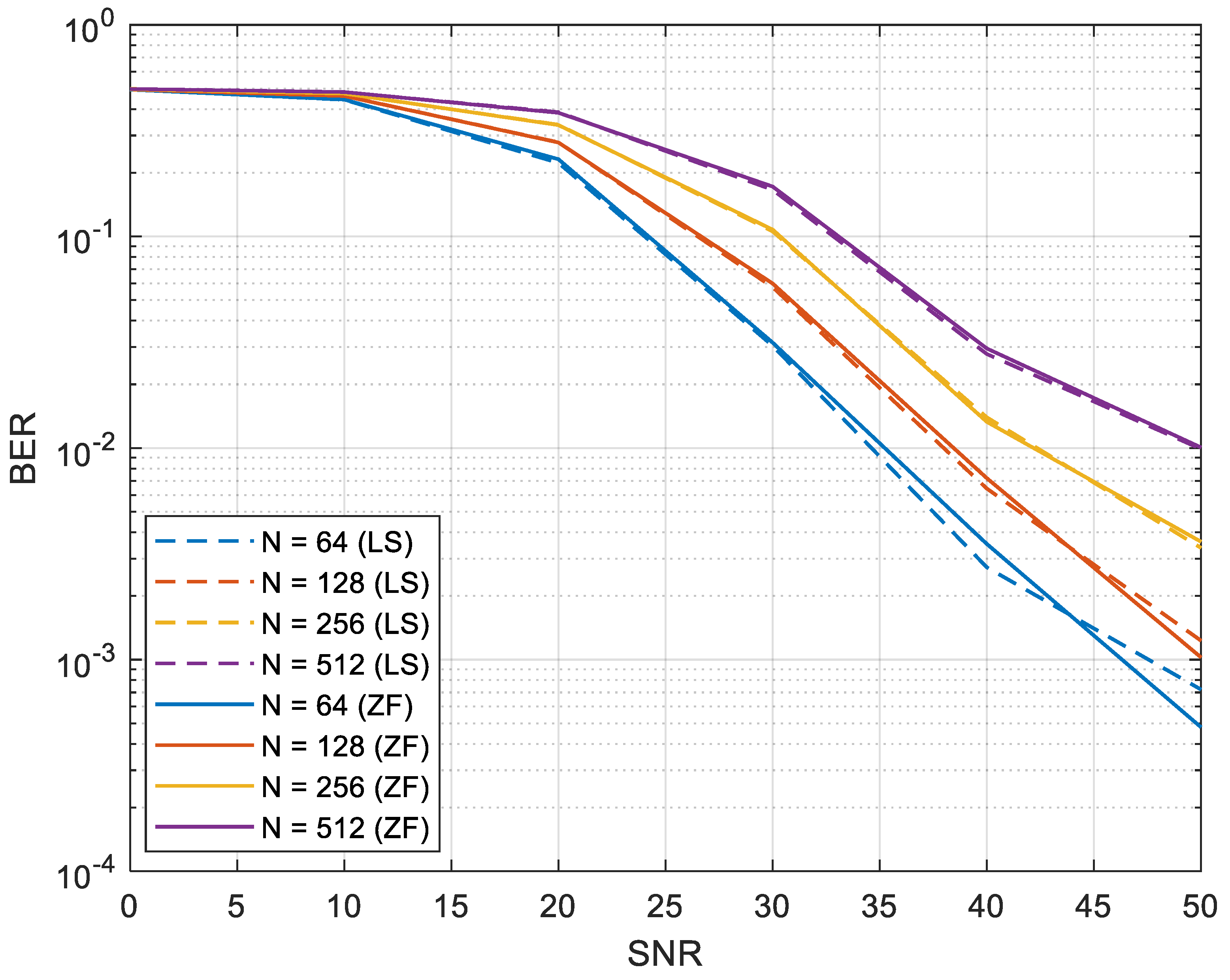
5. Simulation Results

In this section, we present the simulation results for both the pilot-based channel estimation and the linear equalization. To evaluate the performance of the proposed system, a CP-OFDM transceiver communicating over a UWA channel was assumed. The parameters used for the OFDM transceiver are shown in Table 1. In our simulations, we used 10,000 iteration runs for each Eb/N0 point. Every iteration had one OFDM symbol with N subcarriers.
Figure 4 is a BER plot for BPSK CP-OFDM as a function of the number of pilots used when the number of subcarriers were 64, 128, 256, and 512. The transmitter-receiver distance was kept at 50 m. As shown in Figure 4a, 16 pilots offered the best BER performance for 64 subcarriers; using 4 or 8 pilots gave an unacceptably poor performance. This was because 4 or 8 pilots were insufficient to capture the channel behavior. It was also noted that increasing the number of pilots from 16 to 32 marginally deteriorated the BER. For 128 subcarriers, 16 pilots also gave the best BER, as evident from Figure 4b. The case of 256 subcarriers is shown in Figure 4c. It was noted that the best BER was given by 32 and 64 pilots as it was hard to distinguish between the two cases. Figure 4d shows the BER performance when the number of subcarriers was 512. In this case, the best BER was observed when the number of pilots was either 32 or 64. By comparing the four figures, it can be seen that for 64 subcarriers, the optimum number of pilots was one-fourth the number of subcarriers; for 128, it was one-eighth the number of subcarriers; for 256, it was also one-eighth; and, finally, for 512 subcarriers, it was one-sixteenth the number of subcarriers.
The BER performance of the proposed system as a function of the pilot energies is shown in Figure 5. In this figure, the number of pilots was 16, the number of subcarriers was 64, and the transmitter-receiver distance was 50 m. It was noted that as we increased the energy of the pilots, the BER degraded. The reason for this behavior was that as the overall energy of the symbol was kept constant, increasing the pilot energy decreased the energy of the data symbols, which resulted in BER degradation.
Figure 6 shows the BER performance of QPSK CP-OFDM as a function of the equalizers used. In this plot, the number of subcarriers was 128, the number of pilots was 32, and the transmitter-receiver distance was 800 m. As expected, the performance was poor when no equalizer was used. It was also observed that the BER given by both the LS and ZF equalizers was almost the same for a low SNR. At a high SNR, the ZF outperformed the LS equalizer.
Figure 7 shows the BER plots when using the LS and ZF equalizers with multiple transmitter-receiver separations that ranged from 50 to 1250 m. The number of subcarriers was 64 with 16 pilots and BPSK was used in the mapper. As expected, increasing the transmitter-receiver distance deteriorated the BER performance. However, even at 1250 m, the performance was acceptable and a good error correcting code would bring down the BER curve even further.
Figure 8 shows the BER performance for the LS and ZF equalizers when the transmitter-receiver distance was varied from 50 m to 1250 m. The number of subcarriers used was 128 with 32 pilots and BPSK was used in the mapper. The behavior that was observed in Figure 6 and Figure 7 was also noted in these figures. However, the BER was marginally inferior in this case owing to a higher number of subcarriers.
Figure 9 shows the BER performance for the LS and ZF equalizers when the number of subcarriers was varied from 64 to 512 and QPSK was used in the mapper. The number of pilots in both cases was one-fourth the number of subcarriers and the transmitter-receiver distance was kept constant at 500 m. It was observed that the performance with the ZF equalizer was marginally better than that of the LS equalizer. Moreover, as the number of subcarriers increased, the BER degraded owing to an increased ICI. We also provide a summary of our findings in Table 2 for a fixed SNR of 40 dB. It was evident that the BER deteriorated with the number of subcarriers.

6. Conclusions

We investigated the BER performance of CP-OFDM in underwater acoustic (UWA) channels by employing a pilot-based channel estimation and two equalizers, namely, least squares (LS) and zero forcing (ZF) equalizers. The underwater channel model used in this work was based on Rician shadowing. Through this model, we evaluated the performance of a system in UWA channels more realistically. This model also enabled us to adjust the various channel parameters such as fading, Doppler shift, and ambient noise. The main conclusions obtained after extensively simulating the proposed system by varying several system parameters were: (1) the best BER performance was achieved if the number of pilots was kept as one-fourth the number of subcarriers; (2) the BER performance degraded if the energy of the pilots increased whilst keeping the overall symbol energy constant; (3) an acceptable BER performance was observed when using the LS or ZF equalizer; (4) the performance of the ZF equalizer was marginally better than that of the LS equalizer; (5) increasing the number of subcarriers deteriorated the BER performance because of an increased ICI; and (6) an acceptable error performance was observed even at a transmitter-receiver distance of 1250 m with both equalizers. This work could be extended by employing MMSE with soft channel estimates and a decision feedback equalizer (DFE) in a UWA environment. The proposed technique will be further evaluated using a Bellhop core model and/or a Water Mark simulator [43,44]. For trials in a local lake, we plan to implement the proposed model in a GNU radio [45] for Raspberry Pi Zero [46].

Author Contributions

M.M. and I.A.T. conceived the idea and the block diagram of the system. M.M. and I.A.T. implemented the model in MATLAB, ran the simulations, and wrote the manuscript. P.O. conceived and designed the UWA channel model used and contributed to the discussion section. I.A.T. and P.O. reviewed the final version of the manuscript. All authors have read and agreed to the published version of the manuscript.

Funding

This research was funded by a grant from the Spanish Ministry of Science and Innovation through the project "NAUTILUS: Swarms of underwater autonomous vehicles guided by artificial intelligence: its time has come" (PID2020-112502RB / AEI / 10.13039/501100011033).

Institutional Review Board Statement

Not applicable.

Informed Consent Statement

Not applicable.

Acknowledgments

The authors express their gratitude to the Escuela Técnica Superior de Ingeniería de Telecomunicación and the Instituto de Ingeniería Oceánica, Universidad de Málaga, Málaga, Spain. We would also like to thank the College of Computer and Information Systems, Umm Al-Qura University, Makkah, Saudi Arabia.

Conflicts of Interest

The authors declare no conflict of interest.

References

  1. Liu, C.; Zakharov, Y.V.; Chen, T. Doubly Selective Underwater Acoustic Channel Model for a Moving Transmitter/Receiver. IEEE Trans. Veh. Technol. 2012, 61, 938–950. [Google Scholar] [CrossRef]
  2. Akyildiz, I.F.; Pompili, D.; Melodia, T. Challenges for efficient communication in underwater acoustic sensor networks. ACM Sigbed Rev. 2004, 1, 3–8. [Google Scholar] [CrossRef]
  3. Chitre, M.; Shahabudeen, S.; Freitag, L.; Stojanovic, M. Recent advances in underwater acoustic communications & networking. In Proceedings of the IEEE OCEANS, Quebec City, QC, Canada, 15–18 September 2008; pp. 1–10. [Google Scholar]
  4. Khlifi, A.; Bouallegue, R. Performance analysis of LS and LMMSE channel estimation techniques for LTE downlink systems. arXiv 2011, arXiv:1111.1666. [Google Scholar] [CrossRef]
  5. Wang, X.; Wang, J.; He, L.; Song, J. Doubly selective underwater acoustic channel estimation with basis expansion model. In Proceedings of the 2017 IEEE International Conference on Communications (ICC), Paris, France, 21–25 May 2017; pp. 1–6. [Google Scholar]
  6. Schniter, P. Low-complexity equalization of OFDM in doubly selective channels. IEEE Trans. Signal Process. 2004, 52, 1002–1011. [Google Scholar] [CrossRef]
  7. Van De Beek, J.-J.; Edfors, O.; Sandell, M.; Wilson, S.K.; Borjesson, P.O. On channel estimation in OFDM systems. In Proceedings of the 1995 IEEE 45th Vehicular Technology Conference, Countdown to the Wireless Twenty-First Century, Chicago, IL, USA, 25–28 July 1995; pp. 815–819. [Google Scholar]
  8. Giannakis, G.B.; Tepedelenlioglu, C. Basis expansion models and diversity techniques for blind identification and equalization of time-varying channels. Proc. IEEE 1998, 86, 1969–1986. [Google Scholar] [CrossRef] [Green Version]
  9. Yang, L.; Tian, R.; Jia, M.; Li, F. A Modified LS Channel Estimation Algorithm for OFDM System in Mountain Wireless Environment. Procedia Eng. 2012, 29, 2732–2736. [Google Scholar] [CrossRef] [Green Version]
  10. Tiiro, S.; Ylioinas, J.; Myllyla, M.; Juntti, M. Implementation of the least squares channel estimation algorithm for MIMO-OFDM systems. In Proceedings of the International ITG Workshop on Smart Antennas (WSA 2009), Berlin, Germany, 15 November 2009; pp. 16–18. [Google Scholar]
  11. Mason, S.; Anstett, R.; Anicette, N.; Zhou, S. A broadband underwater acoustic modem implementation using coherent OFDM. In Proceedings of the National Conference for Undergraduate Research (NCUR), Washington, DC, USA, 2007. [Google Scholar]
  12. Stojanovic, M. Low Complexity OFDM Detector for Underwater Acoustic Channels; IEEE: Piscataway, NJ, USA, 2006. [Google Scholar]
  13. Stojanovic, M. Adaptive channel estimation for underwater acoustic MIMO OFDM systems. In Proceedings of the 2009 IEEE 13th Digital Signal Processing Workshop and 5th IEEE Signal Processing Education Workshop, Marco Island, FL, USA, 4–7 January 2009; pp. 132–137. [Google Scholar]
  14. Yonggang, W. Underwater acoustic channel estimation for pilot based OFDM. In Proceedings of the 2011 IEEE International Conference on Signal Processing, Communications and Computing (ICSPCC), Xi’an, China, 14–19 September 2011; pp. 1–5. [Google Scholar]
  15. Jiang, R.; Wang, X.; Cao, S.; Zhao, J.; Li, X. Deep neural networks for channel estimation in underwater acoustic OFDM systems. IEEE Access 2019, 7, 23579–23594. [Google Scholar] [CrossRef]
  16. Wang, X.; Wang, X.; Jiang, R.; Wang, W.; Chen, Q.; Wang, X. Channel modelling and estimation for shallow underwater acoustic OFDM communication via simulation platform. Appl. Sci. 2019, 9, 447. [Google Scholar] [CrossRef] [Green Version]
  17. Kamışlıoğlu, B.; Akbal, A. LSE Channel Estimation and Performance Analysis of OFDM Systems. Fırat Univ. Turk. J. Sci. Technol. 2017, 12, 53–57. [Google Scholar]
  18. Junejo, N.U.R.; Esmaiel, H.; Sun, H.; Qasem, Z.A.; Wang, J. Pilot-Based Adaptive Channel Estimation for Underwater Spatial Modulation Technologies. Symmetry 2019, 11, 711. [Google Scholar] [CrossRef] [Green Version]
  19. Preisig, J.; Blair, B.; Li, W. Channel estimation for underwater acoustic communications: Sparse channels, soft input data, and Bayesian techniques. J. Acoust. Soc. Am. 2008, 123, 3892. [Google Scholar] [CrossRef]
  20. Gomes, J.; Barroso, V. Time-reversed OFDM communication in underwater channels. In Proceedings of the IEEE 5th Workshop on Signal Processing Advances in Wireless Communications, Lisbon, Portugal, 11–14 July 2004; pp. 626–630. [Google Scholar]
  21. Ramadan, K.; Dessouky, M.; Elagooz, S.; Elkordy, M.; El-Samie, F.A. Equalization and carrier frequency offset compensation for underwater acoustic OFDM systems. Ann. Data Sci. 2018, 5, 259–272. [Google Scholar] [CrossRef]
  22. Altabbaa, M.T.; Panayirci, E. Channel estimation and equalization algorithm for OFDM-based underwater acoustic communications systems. ICWMC 2017, 113–124. [Google Scholar]
  23. Yin, J.; Ge, W.; Han, X.; Guo, L. Frequency-domain equalization with interference rejection combining for single carrier multiple-input multiple-output underwater acoustic communications. J. Acoust. Soc. Am. 2020, 147, EL138–EL143. [Google Scholar] [CrossRef] [PubMed] [Green Version]
  24. He, Q.; Wang, S.; Zhang, W. Low-complexity MMSE iterative equalization for multiband OFDM systems in underwater acoustic channels. In Proceedings of the 2017 IEEE 9th International Conference on Communication Software and Networks (ICCSN), Guangzhou, China, 6–8 May 2017; pp. 492–497. [Google Scholar]
  25. Sui, Z.; Yan, S. Frequency Channel Equalization Based on Variable Step-Size LMS Algorithm for OFDM Underwater Communications. In Proceedings of the 2019 IEEE International Conference on Signal Processing, Communications and Computing (ICSPCC), Dalian, China, 20–22 September 2019; pp. 1–5. [Google Scholar]
  26. Otnes, R.; Eggen, T.H. Underwater acoustic communications: Long-term test of turbo equalization in shallow water. IEEE J. Ocean. Eng. 2008, 33, 321–334. [Google Scholar] [CrossRef]
  27. Cai, X.; Giannakis, G.B. Error probability minimizing pilots for OFDM with M-PSK modulation over Rayleigh-fading channels. IEEE Trans. Veh. Technol. 2004, 53, 146–155. [Google Scholar] [CrossRef]
  28. Kay, S.M. Fundamentals of Statistical Signal Processing; Prentice Hall PTR: Hoboken, NJ, USA, 1993. [Google Scholar]
  29. Murad, M.; Tasadduq, I.A.; Otero, P.J.I.A. Towards multicarrier waveforms beyond OFDM: Performance analysis of GFDM modulation for underwater acoustic channels. IEEE Access 2020, 8, 222782–222799. [Google Scholar] [CrossRef]
  30. Bocus, M.J.; Agrafiotis, D.; Doufexi, A. Underwater acoustic video transmission using MIMO-FBMC. In Proceedings of the 2018 OCEANS-MTS/IEEE Kobe Techno-Oceans (OTO), Kobe, Japan, 28–31 May 2018; pp. 1–6. [Google Scholar]
  31. Urick, R.J. Sound Propagation in the SEA; Peninsula Publishing: Los Altos, CA, USA, 1982. [Google Scholar]
  32. Wan, L. Underwater Acoustic OFDM: Algorithm Design, DSP Implementation, and Field Performance. Ph.D. Thesis, University of Connecticut, Storrs, CT, USA, 2014. [Google Scholar]
  33. Philip, M.; Morse, K.U.I. Theoretical Acoustics; Princeton University Press: Princeton, NJ, USA, 1986. [Google Scholar]
  34. Roth, P.O. Fundamentos de Propagación de Ondas; Universidad de Malaga, Manual: Malaga, Spain, 2015. [Google Scholar]
  35. Medwin, H. Speed of sound in water: A simple equation for realistic parameters. J. Acoust. Soc. Am. 1975, 58, 1318–1319. [Google Scholar] [CrossRef]
  36. Kulhandjian, H.; Melodia, T. Modeling underwater acoustic channels in short-range shallow water environments. In Proceedings of the ACM International Conference on Underwater Networks & Systems, Rome, Italy, 12–14 November 2014; pp. 1–5. [Google Scholar]
  37. Radosevic, A.; Proakis, J.G.; Stojanovic, M. Statistical characterization and capacity of shallow water acoustic channels. In Proceedings of the OCEANS 2009-EUROPE, Bremen, Germany, 11–14 May 2009; pp. 1–8. [Google Scholar]
  38. Ruiz-Vega, M.C.C.; Paris, J.F.; Otero, P. Ricean shadowed statistical characterization of shallow water acoustic channels for wireless communications. In Proceedings of the IEEE Conference Underwater Communications: Channel Modelling & Validation, UComms, Sestri Levante, Italy, 12–14 September 2012. [Google Scholar]
  39. Jeruchim, M.; Balaban, P.; Shanmugan, K.S. Simulation of Communication Systems, 2nd ed.; Kluwer Academic/Plenum: New York, NY, USA, 2000. [Google Scholar]
  40. Tasadduq, I.A.; Murad, M.; Otero, P. CPM-OFDM Performance over Underwater Acoustic Channels. Engineering 2021, 9, 1104. [Google Scholar] [CrossRef]
  41. Stojanovic, M. On the relationship between capacity and distance in an underwater acoustic communication channel. ACM SIGMOBILE Mob. Comput. Commun. Rev. 2007, 11, 34–43. [Google Scholar] [CrossRef]
  42. Hebbar, R.P.; Poddar, P.G. Generalized frequency division multiplexing–based acoustic communication for underwater systems. Int. J. Commun. Syst. 2020, 33, e4292. [Google Scholar] [CrossRef]
  43. Walree, P.V.; Otnes, R.; Jenserud, T. The Watermark manual and user’s guide-version 1.0., User Manual. 2016. [Google Scholar]
  44. van Walree, P.A.; Socheleau, F.-X.; Otnes, R.; Jenserud, T. The watermark benchmark for underwater acoustic modulation schemes. IEEE J. Ocean. Eng. 2017, 42, 1007–1018. [Google Scholar] [CrossRef] [Green Version]
  45. Blossom, E. GNU radio: Tools for exploring the radio frequency spectrum. Linux J. 2004, 2004, 4. [Google Scholar]
  46. Pi, R. Raspberry Pi Zero: The $5 Computer. Available online: https://www.raspberrypi.org/products/raspberry-pi-zero/ (accessed on 28 October 2021).
Figure 1. A typical CP-OFDM transceiver with a channel estimation using pilots.
Jmse 09 01382 g001
Figure 2. Shallow underwater acoustic channel model.
Jmse 09 01382 g002
Figure 3. Channel impulse response for a shallow underwater acoustic channel.
Jmse 09 01382 g003
Figure 4. BER as a function of the number of pilots for CP-OFDM with a transmitter-receiver distance of 50 m: (a) 64 subcarriers; (b) 128 subcarriers; (c) 256 subcarriers; (d) 512 subcarriers.
Jmse 09 01382 g004
Figure 5. BER as a function of the pilot energies for CP-OFDM with 64 subcarriers, a transmitter-receiver distance of 50 m, and the number of pilots as 16.
Jmse 09 01382 g005
Figure 6. BER as a function of the equalizer used for QPSK CP-OFDM with 128 subcarriers, a transmitter-receiver distance of 800 m, and the number of pilots as 32.
Jmse 09 01382 g006
Figure 7. BER of CP-OFDM when using the LS and ZF equalizers as a function of the transmitter-receiver distance with 64 subcarriers and 16 pilots.
Jmse 09 01382 g007
Figure 8. BER of CP-OFDM when using the LS and ZF equalizers as a function of the transmitter-receiver distance with 128 subcarriers and 32 pilots.
Jmse 09 01382 g008
Figure 9. BER of CP-OFDM when using the LS and ZF equalizers as a function of the number of subcarriers with a transmitter-receiver distance of 500 m and the number of pilots one-fourth the number of subcarriers.
Jmse 09 01382 g009
Table 1. Simulation parameters.
TypeParametersValues
TransceiverNumber of Subcarriers
Number of Pilots
Modulation Scheme
CP Length
Data Rates
64 ,   128 ,   256 ,   512
8 to 128 (typically one-fourth of the number of subcarriers)
BPSK, QPSK
One-fourth of the number of subcarriers
8 kbps for BPSK and 16 kbps for QPSK
ChannelBandwidth
Carrier Frequency
Number of Taps
Distance
Transmitter Depth
Receiver Depth
Doppler Frequency
Path Gains
Delay
10 kHz
30 kHz
3
50 to 1250 m
20 m
20 m
10 Hz
( 0 ; 8.3 ; 4.4 ; 6.2 )
( 0 ; 1.5 × 10 3 ; 4 × 10 3 ; 7 × 10 3 ) s
Table 2. BER performance for 64, 128, 256, and 512 subcarriers at a fixed distance of 500 m.
EqualizerN = 64N = 128N = 256N = 512
LS 0.002729 0.006434 0.0133 0.02782
ZF 0.003521 0.007205 0.01396 0.02955
Publisher’s Note: MDPI stays neutral with regard to jurisdictional claims in published maps and institutional affiliations.

