1. Introduction
With the increasing demand of renewable energy, one of the mature technologies for large-scale energy storage is pumped-storage power stations [
1,
2]. The vigorous development of pumped-storage power plants can provide sufficient storage for energies generated by both the wind and the sun. As the core part of pumped-storage power station, pump turbines can achieve peak shaving and valley filling of the power grid through the conversion between pump mode and turbine mode to optimize grid load [
3]. Frequent startup and shutdown and operating conditions’ conversion are the basic requirements for pump turbines [
4,
5]. During startup, the guide vane is gradually opened from the closed state, and the unit experiences the S characteristics area before the unit is connected to the grid [
6].
A typical full characteristic curve of a pump turbine may have two S characteristic areas. One is the direction of rotation of the turbine and the other is the direction of rotation of the pump. The S characteristic of the turbine rotation direction is more obvious than the pump rotation direction, which brings a series of difficulties to the power generation mode [
7,
8]. In the S area, the same speed may correspond to 3 different flow rates, including the negative flow in the reverse pump mode. When the unit is operating in the S area, especially under no-load conditions, the flow is unstable [
9,
10]. Staubli [
11] pointed out that the instability of S characteristic area is related to the slope of the unit characteristic curve under no-load conditions. Gentner [
12] found that the blocking effect of the vortex flow in the vaneless zone under no-load opening is an important source of the instability of the S area. The study of vortex flow in the vaneless zone has also been reported by many scholars [
13,
14,
15]. The misaligned guide vanes (MGV) have a controlling effect on the stability of the S area [
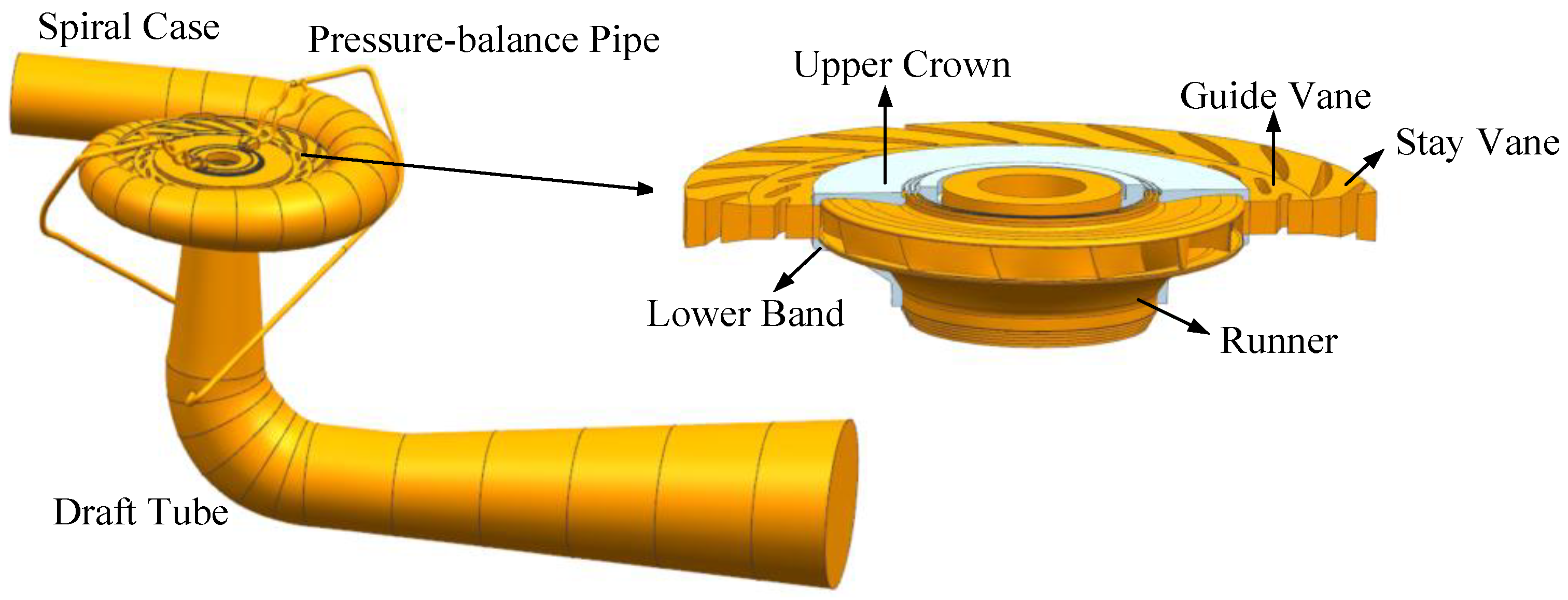
16]. However, for actual operation, the three-dimensional flow field model not only includes the spiral case, state vane, guide vane, runner, and draft tube, but also needs to consider the influence of runner gap and pressure-balance pipe. As shown in
Figure 1, the space between the top cover and the upper crown of the runner is the upper crown gap, and the space between the bottom cover and the lower band of the runner is the lower band gap. There are two pressure-balance pipes of the unit, which are located between the main shaft seal and the upper crown gap seal ring, and are connected to the draft tube through the top cover of the unit.
As mentioned above, the unstable flow in the unit under no-load conditions is related to the instability of S area. In addition, it complicates the force on the runner. Under startup no-load conditions, the axial force and radial force of the unit will change greatly [
17]. Li [
18,
19] conducted that the high-speed vortex in the vaneless zone at a no-load condition caused a significant increase in the radial force of the runner. Meanwhile, the pump turbine is installed vertically, and the changing characteristics of the axial water thrust directly affect the safe and stable operation of the unit. Excessive axial water thrust causes accidents such as unit lifting and tile burning [
20,
21]. Runner gap and pressure-balance pipe are important factors that affect the axial water thrust of the unit. The instantaneous characteristics of the axial water thrust of the runner under no-load conditions have not been studied in depth. In particular, the influence of the upper crown gap and the lower band gap on the axial water thrust of the runner needs further discussion.
In this paper, a numerical simulation was conducted to analyze the internal flow characteristics of the pump turbine at the lowest head under no-load condition. Firstly, a pump turbine model including the upper crown gap, the lower band gap, and the pressure-balance pipe was established. The mesh division was performed, and the accuracy of the numerical method was verified by empirical results. Then, the pressure pulsation of the runner at different working conditions during the no-load process is compared. Finally, a working condition was selected to show that the vortex characteristics of the vaneless zone, and analyzed the instantaneous characteristics of the axial water thrust of each part of the runner.
2. Methods
The Navier–Stokes equations of fluid momentum and the flow continuity equation were used to analyze the complicated flow field in the pump turbine.
where
is water density,
p is the pressure,
is the flow velocity,
is the dynamic viscosity,
is the external momentum source term, and
is the Reynolds stresses. The relationship between the Reynolds stresses and the mean velocity gradients is established by the eddy viscosity assumption.
where
is the Kronecker delta (when
,
= 1; when
,
= 0), and
is the eddy viscosity and can be solved by the turbulent kinetic energy,
k and the turbulent frequency,
.
The starting point of the present formulations is the
k-ω model developed by Wilcox as follows:
Since the Wilcox model is very sensitive to freestream conditions and the inlet value has a significant influence on the calculation results. Menter [
22] developed the SST
k-ω model (Shear Stress Transport
k-ω), which used the
k-ω model near the surface and the
k-ε model in the outside region. The
k-ω model was thereby multiplied by a blending function
F1 and the
k-ε model by a function (1 −
F1).
The functions in the model can be solved by the linear relationship in Equation (7).
where
,
,
,
,
,
,
,
,
.
The
k-ω based SST model accounts for the transport of the turbulent shear stress by limiting eddy viscosity shown in Equations (8)–(10). It gives highly accurate predictions of the onset and the amount of flow separation under adverse pressure gradients [
23,
24]. Therefore, the SST
k-ω is used in present simulation.
where
,
S is an invariant measure of the strain rate,
y is the distance to the nearest wall, and
is the kinematic viscosity.
The three-dimensional model of the pump turbine of a power station is shown in
Figure 1, including the spiral case, stay vane, guide vane, runner, upper crown seal gap, lower band seal gap, pressure-balance pipe, and draft tube. The pump turbine studied in this paper featured 22 stay vanes, 22 guide vanes, and 13 runner blades.
The simulation was carried out in ANSYS CFX with the inlet set to total pressure and the outlet set to static pressure. The other walls were set as no slip walls. The runner and the gap between runners were set as a rotating domain, and the other regions are static domains. The transient motion interfaces of the rotating domain and the static domain were set to transient rotor stator. The turbulence model selected the SST k-ω model. The time step was . In the solution of the incompressible flow field by RANS (Reynolds-averaged Navier-Stokes equations), SIMPLEC (SIMPLE Consistent) was used to realize the coupling of the velocity field and the pressure field, and the convergence residual was .
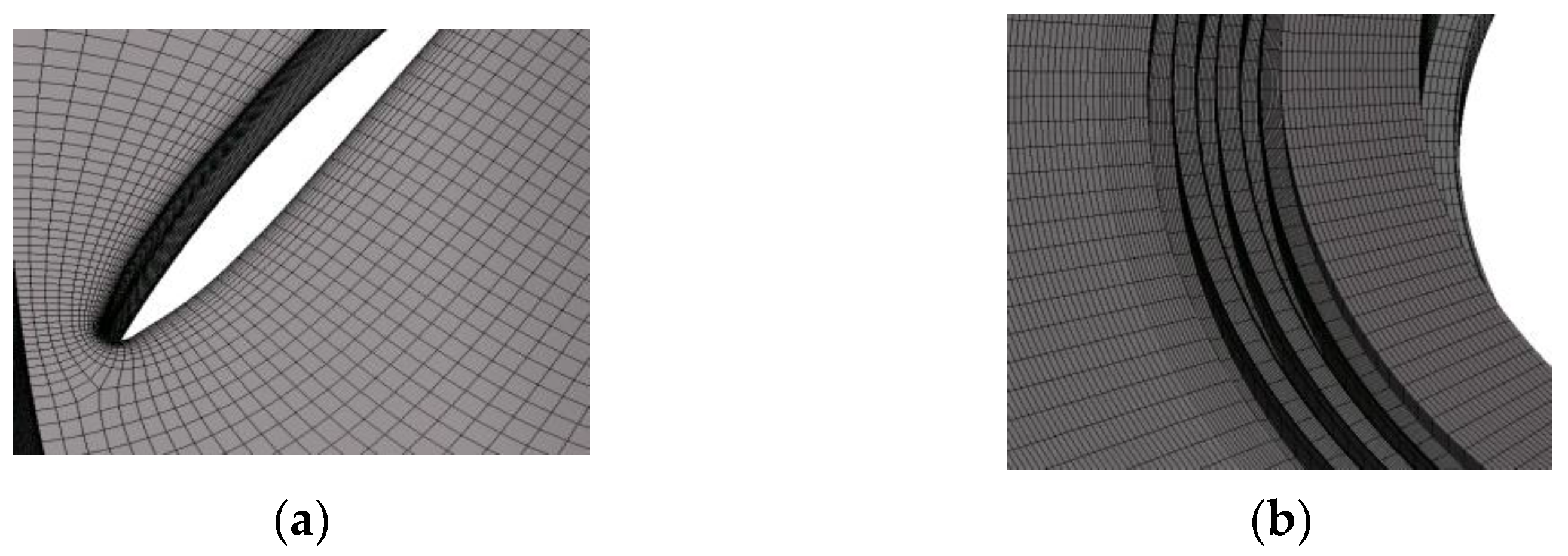
The pump turbine adopted a combination of structured mesh and unstructured mesh. The structured hexahedral mesh was used for the runner and the seal gap. Moreover, mesh refinement was performed on the blade surface and the gap labyrinth ring. The mesh result was shown in
Figure 2.
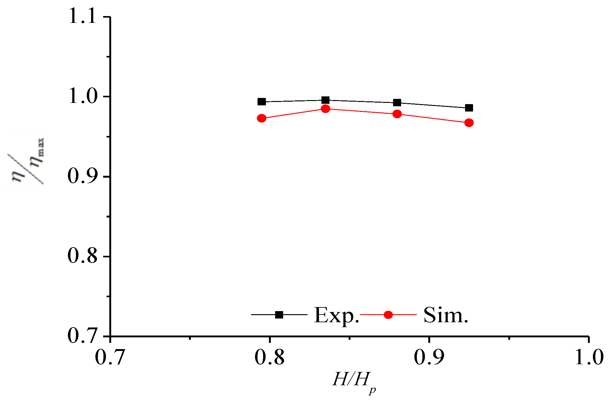
The efficiency of the unit under different water heads was shown in
Figure 3. The numerical simulation results of the pump turbine basically agree with the curve of the test results. Compared with the test results, this paper considered the energy loss of the runner gap, so the simulation result was slightly smaller.
3. Results and Discussion
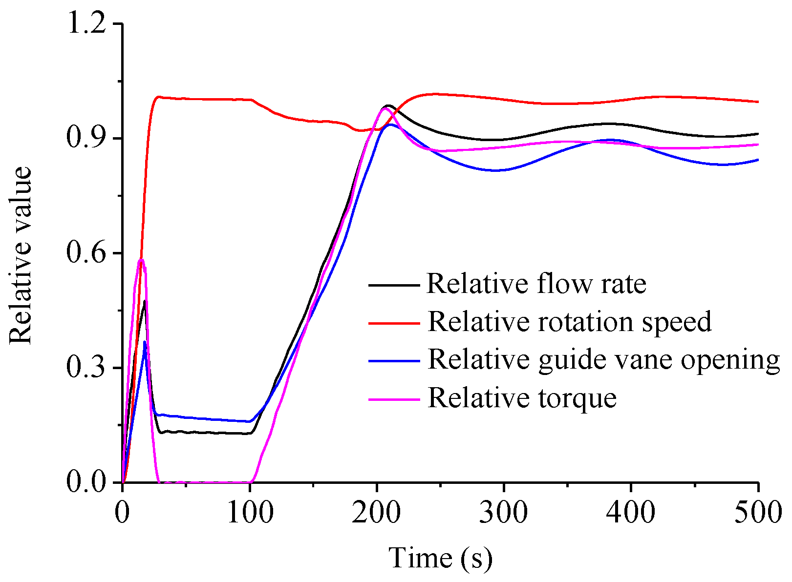
The relative rotation speed, relative flow rate, and relative guide vane opening during the startup process when the unit at the lowest water head are shown in
Figure 4. From t = 0 s to t = 18 s, when the opening of the guide vane increases the flow rate increases, resulted in the increase of the energy acting on the runner, then the speed rose rapidly, approaching the rated speed. The guide vane slightly closed up to prevent the speed from rising too fast and exceeding the rated speed. From t = 18 s to t = 28 s, the opening of the guide vane decreased and the flow rate decreased. At the same time, the water was still working on the runner, the speed of the runner was also increasing. After the unit was connected to the power grid, it entered the no-load operation area.
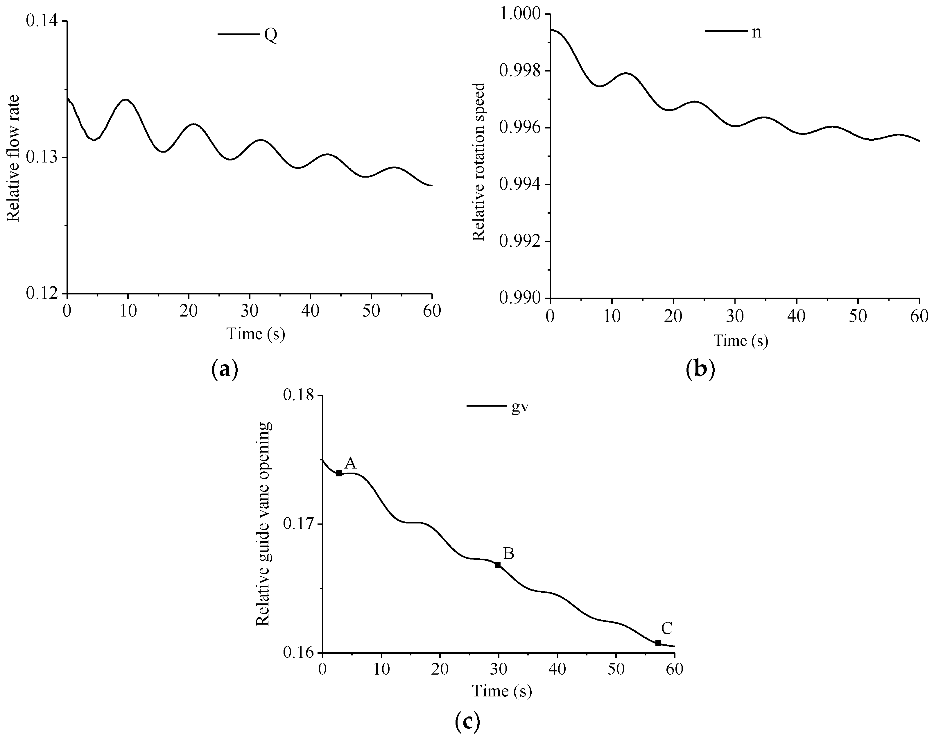
Figure 5 shows the changes of the flow rate, the rotation speed, and the guide vane opening when the relative torque was 0. The relative flow rate varied from 0.135 to 0,128, the speed varied from 1.0 to 0.996, and the guide vane opening varied from 0.175 to 0.16. The pressure pulsation under three working conditions A, B, and C were selected for comparison. The operating parameters of the three working conditions are shown in
Table 1.
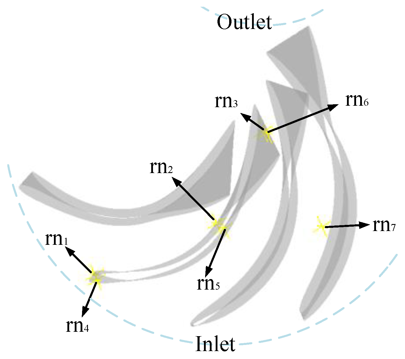
Figure 6 shows the distribution of monitoring points in the runner, where rn
1-rn
3 are located on the suction surface of the blade, rn
4-rn
6 are located on the pressure surface of the blade, and rn
7 in the runner’s flow channel.
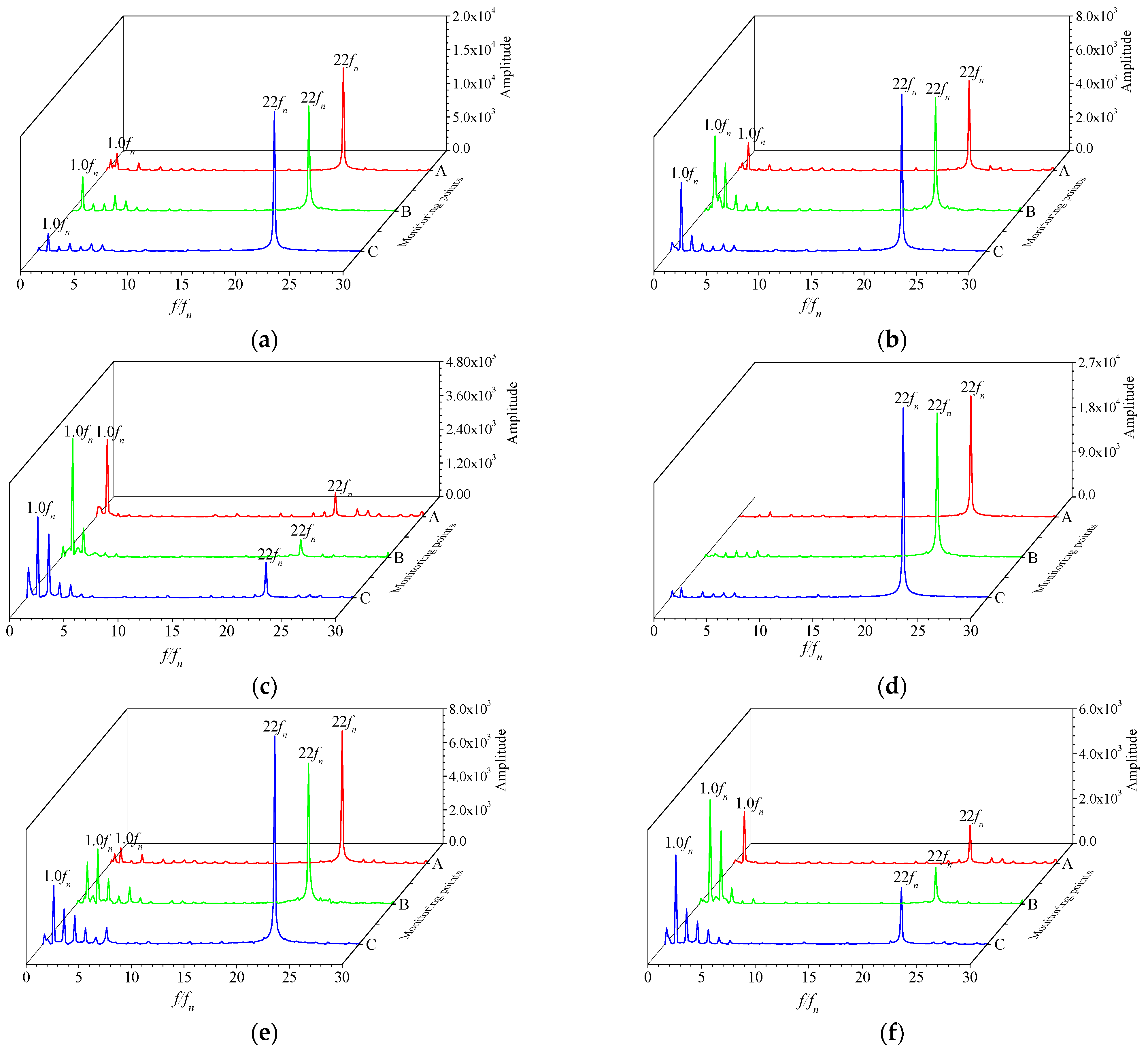
As shown in
Figure 7, rn
1 is located at the inlet of the blade suction surface. Under the influence of the rotor–stator interaction by the 22 guide vanes, the main frequency of rn
1 was 22
fn (
fn is the rotational frequency of the runner). rn
2 is located in the middle of the suction surface of the blade, away from the inlet side, and the influence of the rotor-stator interaction was weakened. The pressure pulsation amplitude of 22
fn decreased, and the pressure pulsation amplitude of 1.0
fn increased. rn
3 was located at the outlet of the suction surface of the blade, and the dominant frequency was 1.0
fn. The dominant frequency at the pressure surfaces of rn
4, rn
5, and rn
6 were the same as that of rn
1, rn
2, and rn
3. The monitoring points nearby the inlet of the blade was affected by the rotor–stator interaction. rn
7 is located in the middle of the flow channel, and still had the frequency of the rotor–stator interaction of 22
fn.
As shown in Equation (14), the relative axial water thrust coefficient, F
y*, is defined. The calculation of F
y is based on the results of CFD (Computational Fluid Dynamics) calculations and extracts the axial water thrust of the runner.
where
m is the weight of the rotating parts of the pump turbine unit.
g is the acceleration due to gravity, 9.8 kg/N.
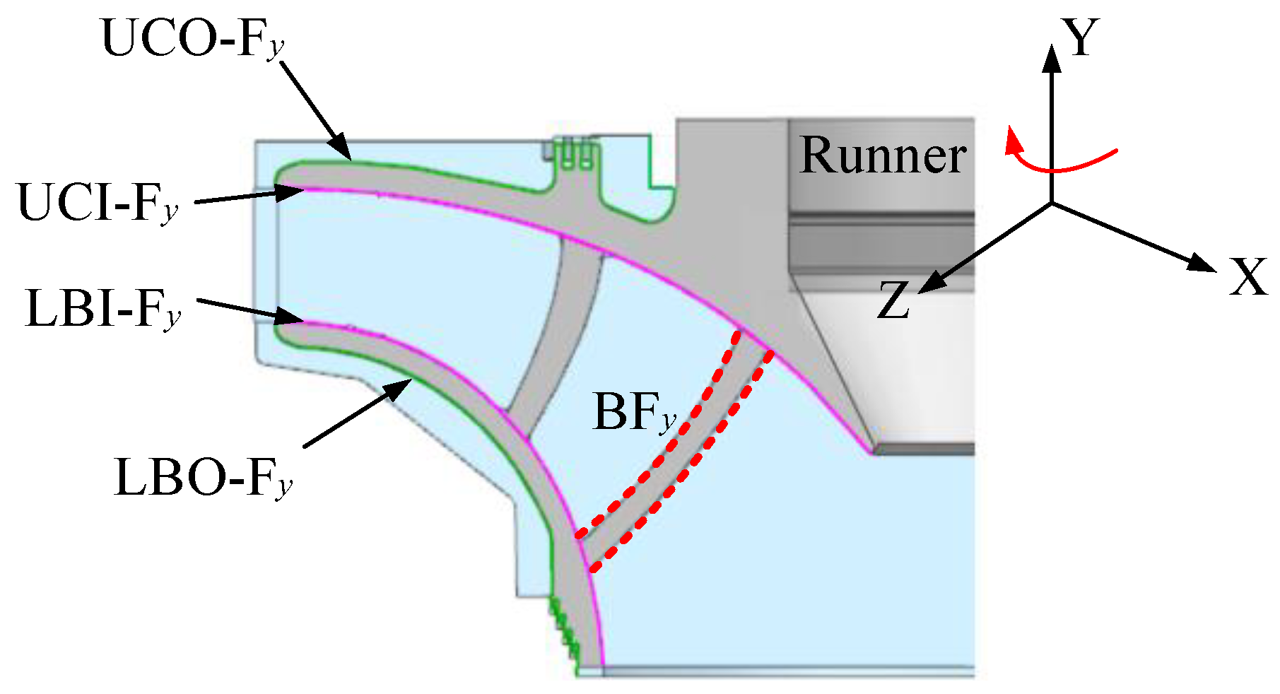
Figure 8 is an exploded view of the axial water thrust of the runner, including the axial water thrust of the outer surface of the upper crown of the runner (UCO-F
y), the axial water thrust of the inner surface of the upper crown of the runner (UCI-F
y), the total axial water thrust of the upper crown of the runner(UC-F
y), the axial water thrust of the outer surface of the lower band of the runner (LBO-F
y), the axial water thrust of the inner surface of the lower band of the runner (LBI-F
y), the total axial water thrust of the lower band of the runner(LB-F
y), the axial water thrust of the pressure and suction surfaces of the runner blades (BF
y), and the axial water thrust of the runner (RN-F
y).
Figure 9 shows the axial water thrust of the runner under conditions A, B, and C. The results show that the axial water thrust of the runner was smaller than the gravity of the runner. In the no-load process, it changed steadily with time, showing a trend of small increase and gradual decrease.
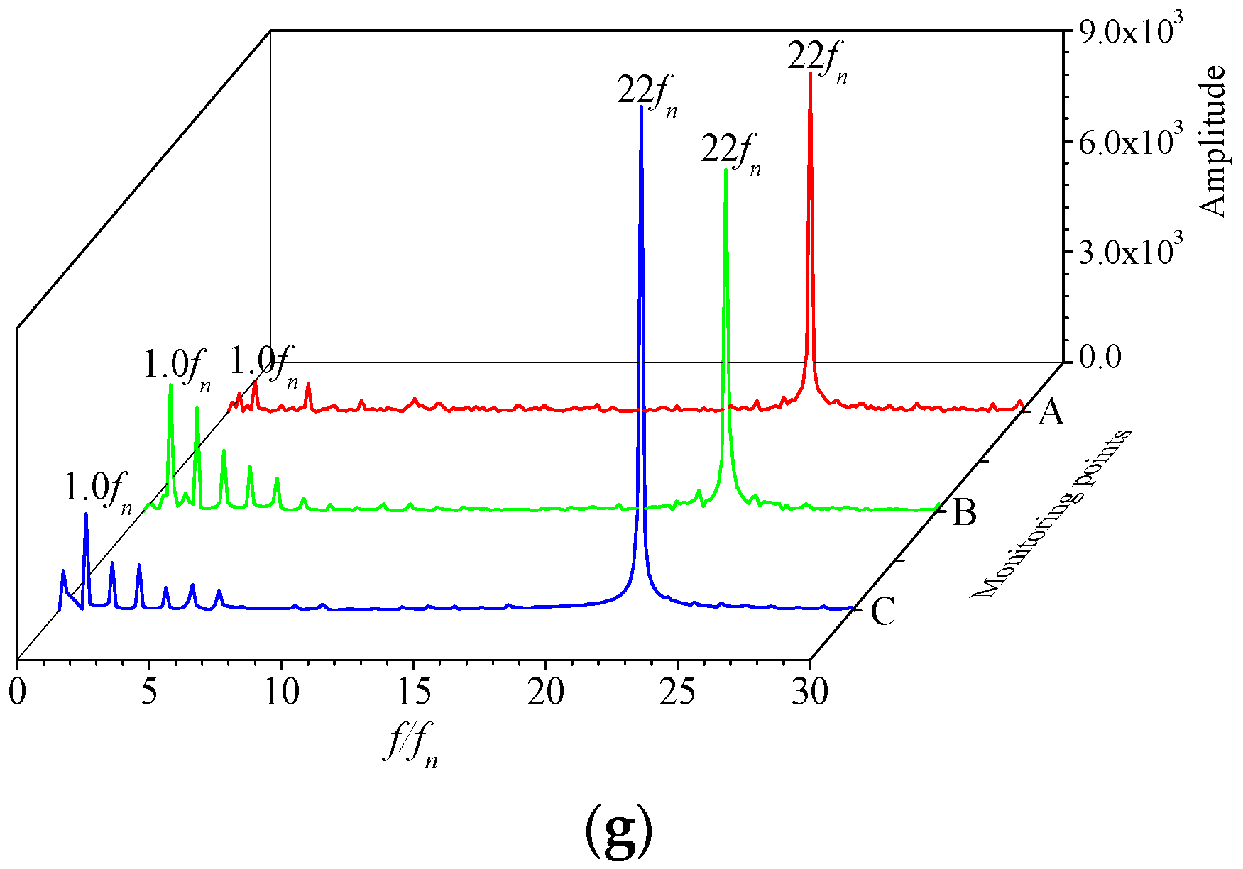
During the no-load process, the values of the flow rate, the rotation speed, and the guide vane opening of the unit are in small ranges. Therefore, under the different working conditions, A, B and C, the main frequency of pressure pulsation at each monitoring point in the runner was basically the same. The amplitude of the pressure pulsation had some differences, but the pulsation magnitude was the same. Moreover, the axial water thrust of the runner did not change much during the no-load process. Therefore, the unsteady calculation of a certain operating point can be selected to reflect the instantaneous flow characteristics of the unit in the no-load process. The following is the unsteady flow field analysis of the pump turbine under A working condition.
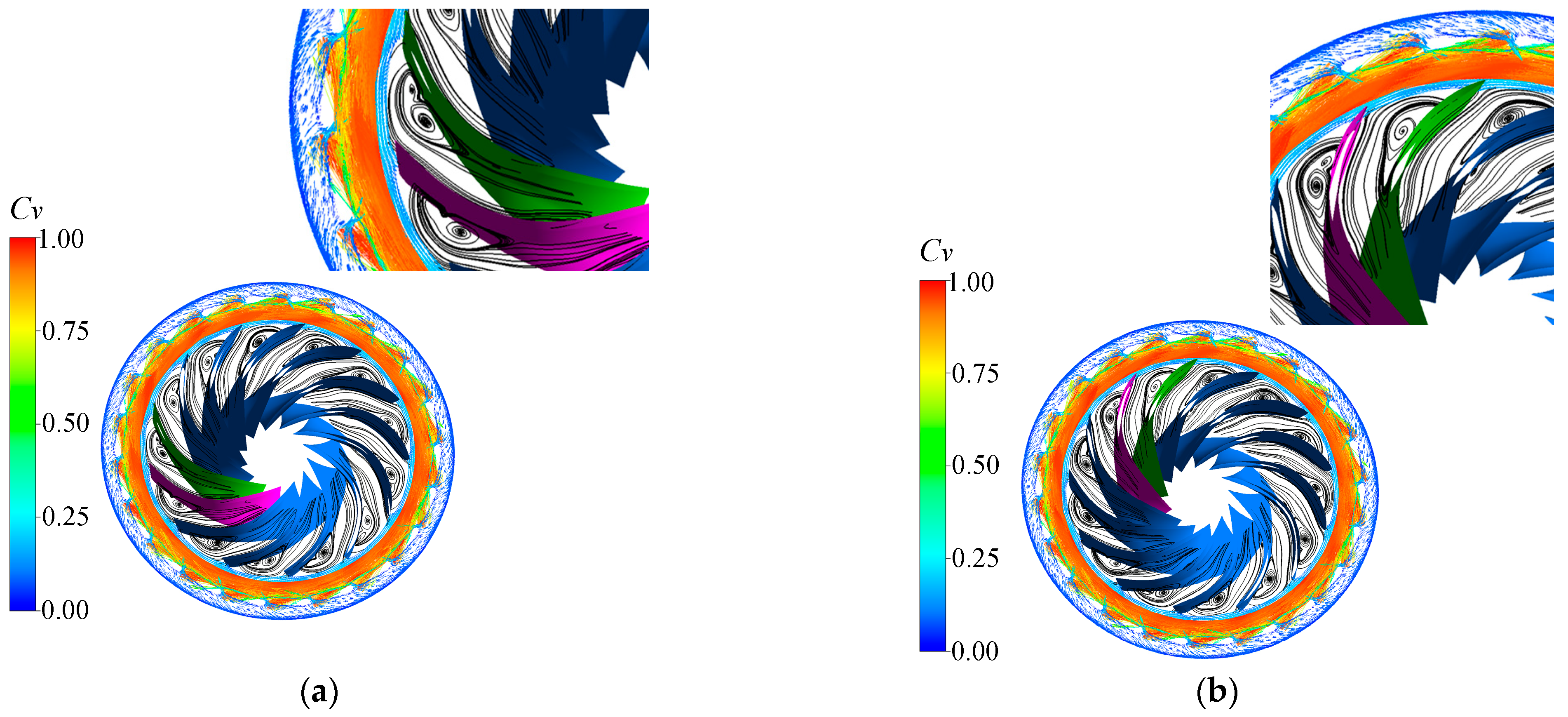
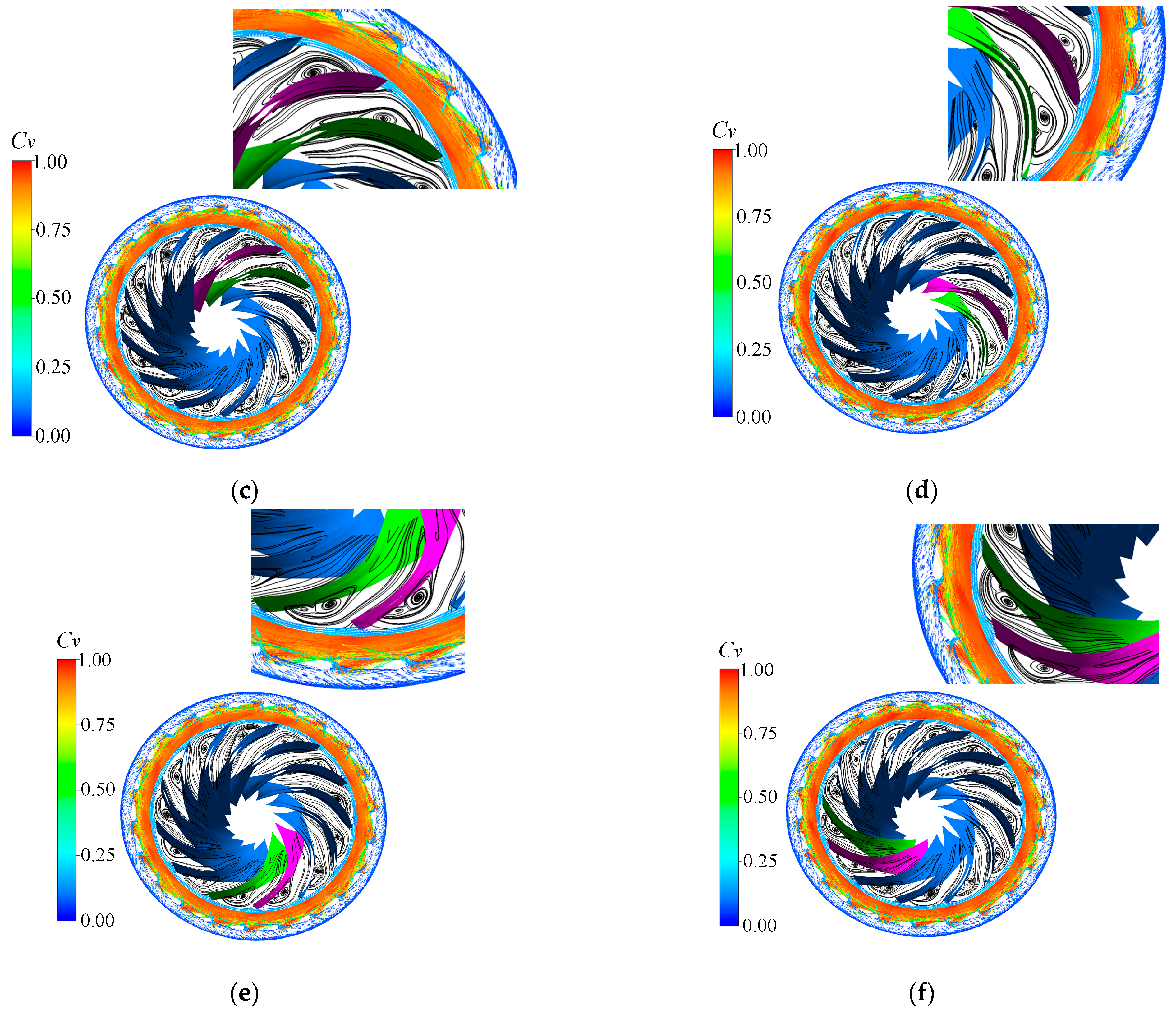
Figure 10 shows the velocity vector and streamline distribution of the guide vane-runner area. It can be seen from the figure that in the no-load process, the guide vane had a small opening, a high rotation speed, and a low flow rate. Therefore, the speed difference between the pressure surface and the suction surface of the guide vane was relatively high, and a high-speed ring was formed in the vaneless area. A channel vortex was generated near the inlet of the runner, and the shape of the vortex was stable in one period.
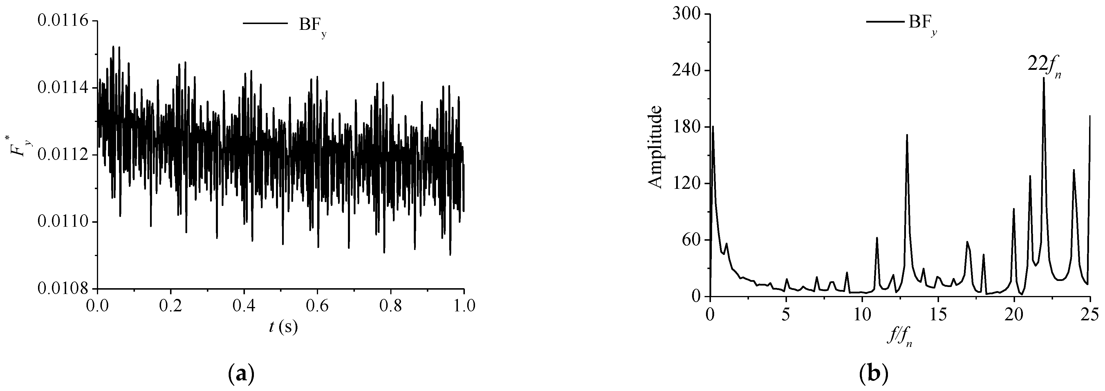
The axial water thrust of each part shown in
Figure 8 was analyzed, and the contribution of the gap flow to the axial water thrust of the runner was clarified. In
Figure 11, the axial water thrust of the blade (BF
y) is small, about 1/10 of the gravity of the rotating part of the unit, and its direction is the opposite of the gravity (+Y). Moreover, the BF
y changes periodically, and its main frequency is the rotor–stator interaction frequency, 22
fn.
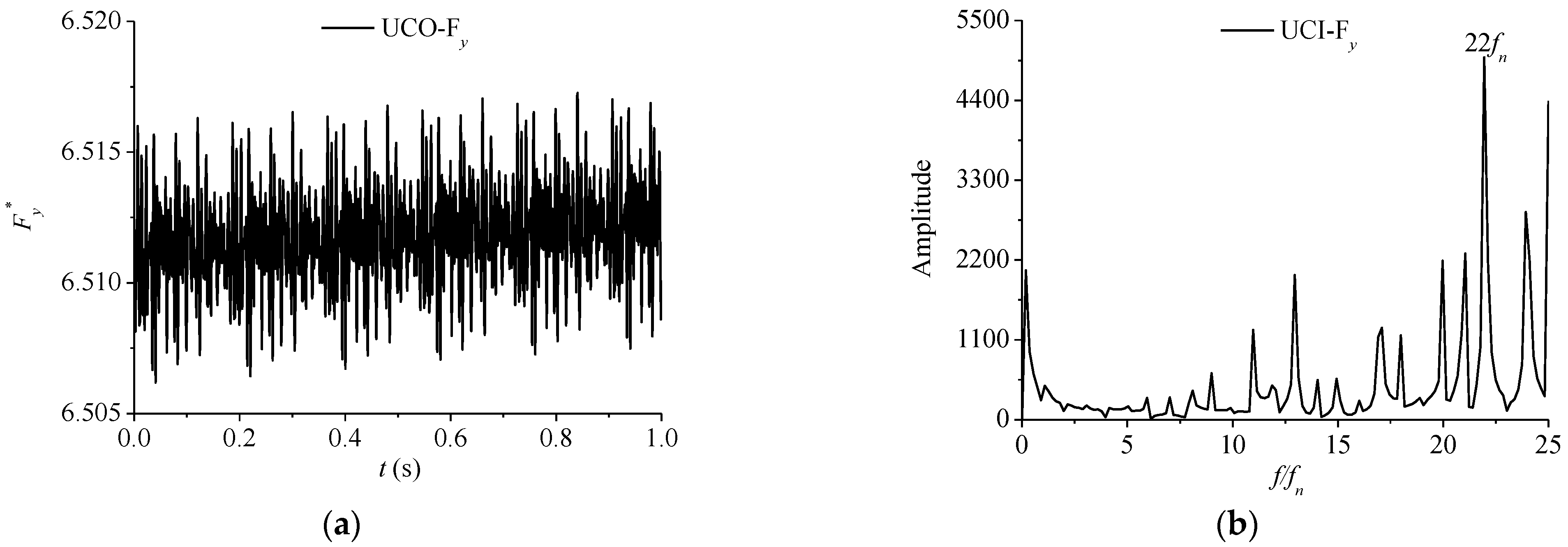
Figure 12 shows the axial water thrust on the inner surface of the upper crown of the runner (UCI-F
y). The results show that the UCI-F
y was very large, with a small fluctuation range over time, which was basically about 6.5 times the gravity of the rotating part of the unit (6.5 mg), and the direction was at the +Y axis. It changed with time periodically and was affected by rotor–stator interaction. The dominant frequency was 22
fn.
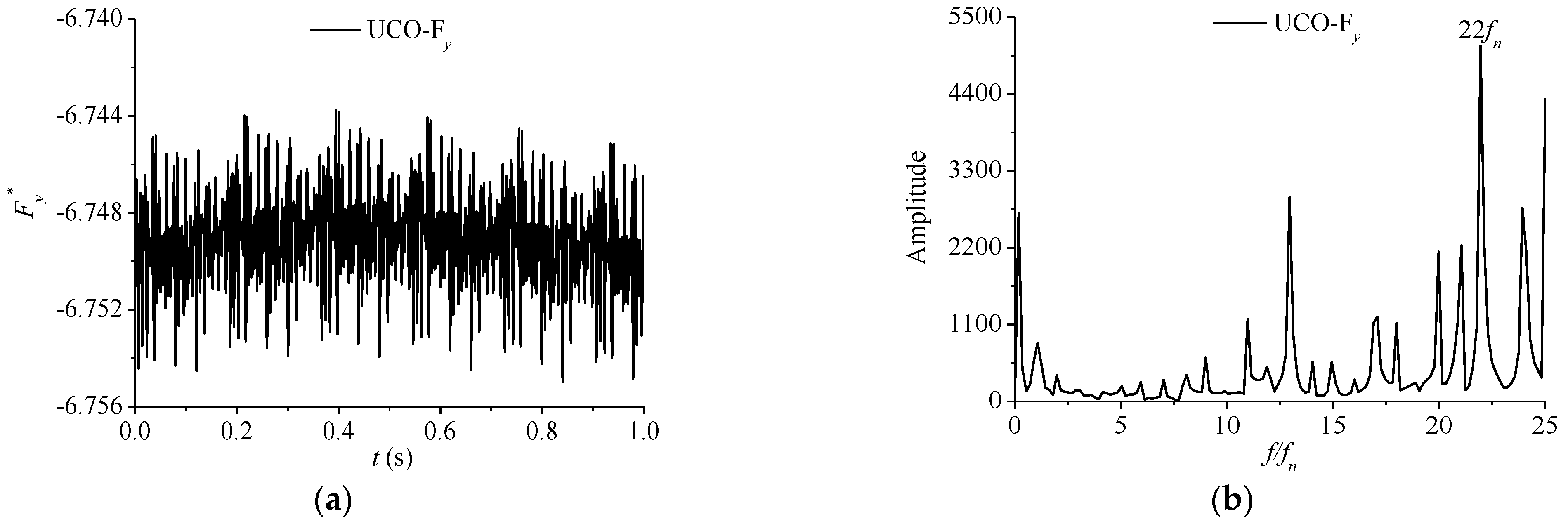
Figure 13 shows the axial water thrust on the outer surface of the upper crown of the runner (UCO-F
y). The UCO-F
y periodically changes along the -Y axis, and the absolute value was greater than that of the inner surface of the upper crown, about 6.7 mg. The main frequency was 22
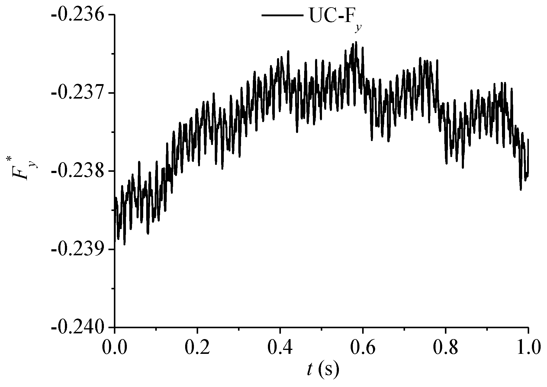
fn. The total axial water thrust on the upper crown of the runner was downward (-Y), about 0.24 mg, and its vibration is shown in
Figure 14.
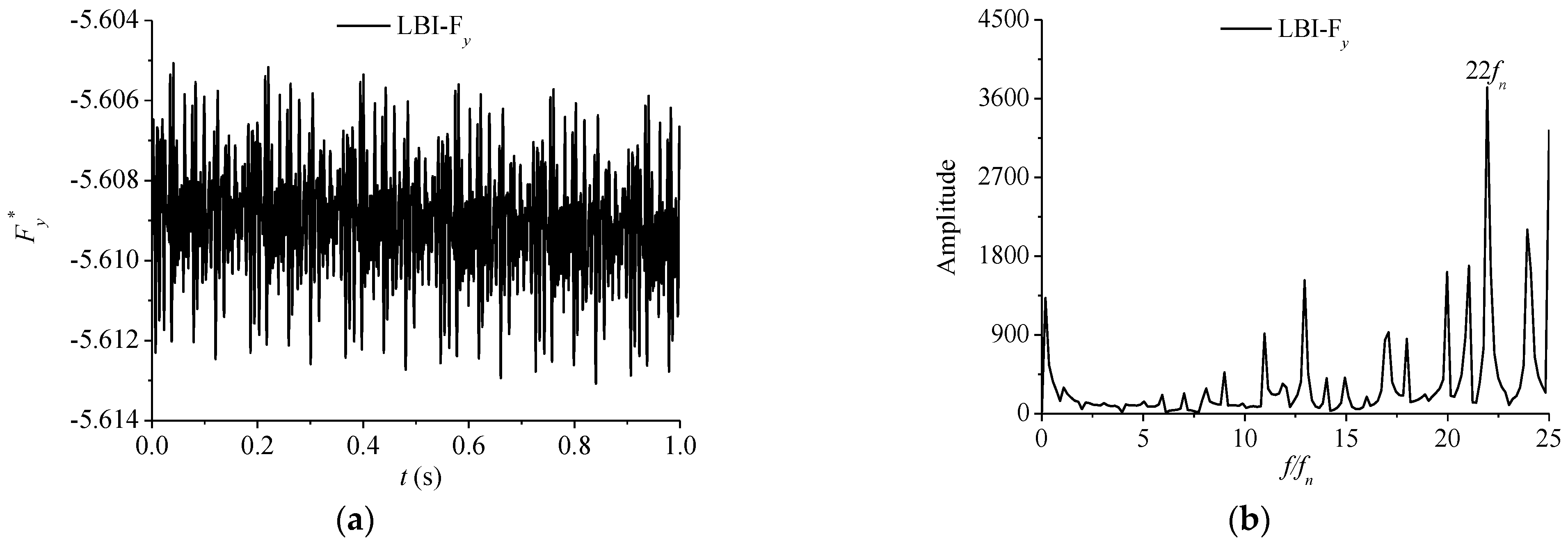
Figure 15 shows the axial water thrust on the inner surface of the lower band of the runner (LBI-F
y). The LBI-F
y changed along the -Y axis, about 5.6 mg. The main frequency of the periodic change was 22
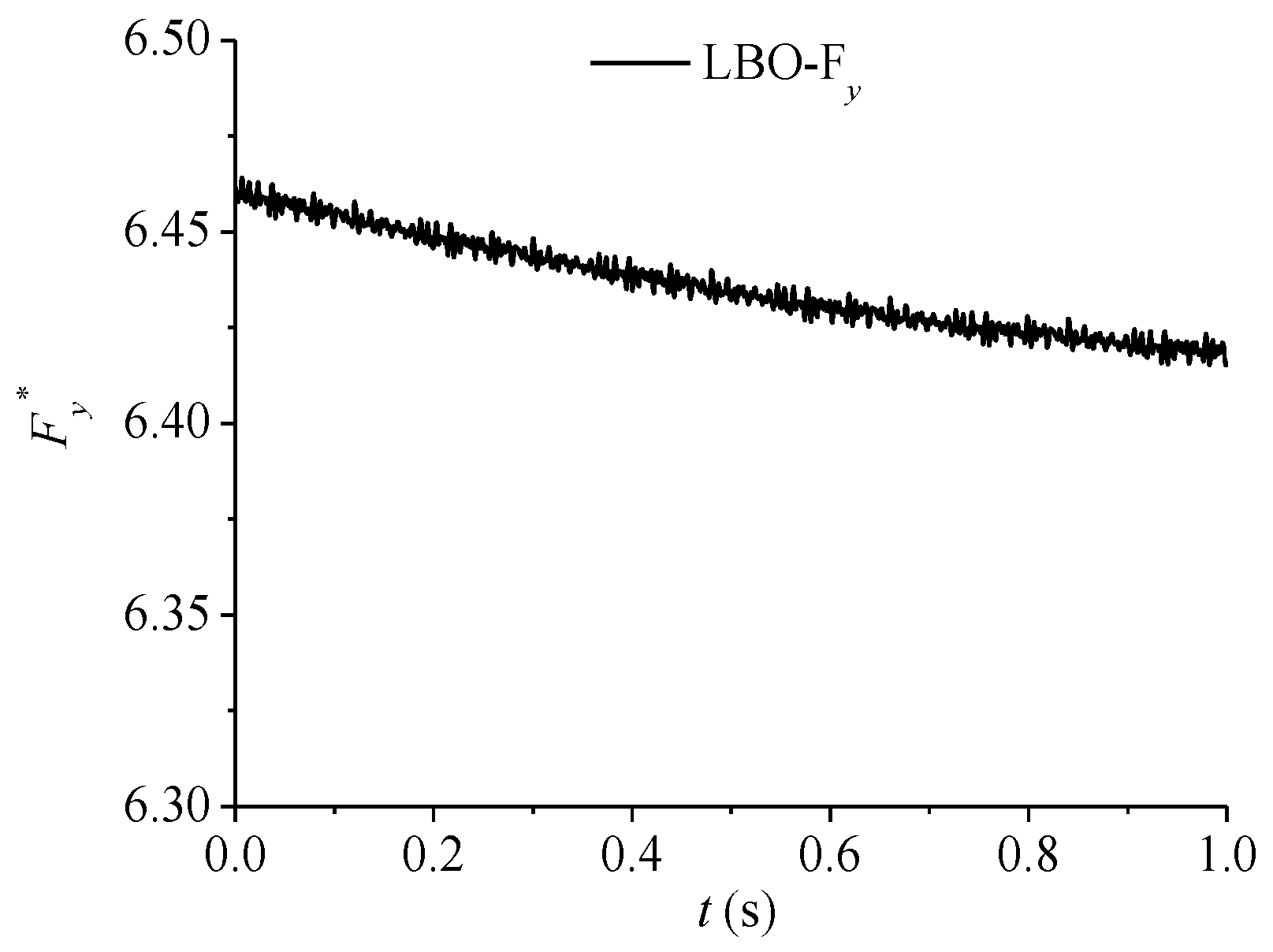
fn. In
Figure 16, it can be seen that the axial water thrust on the outer surface of the lower band of the runner (LBO-F
y) is about 6.45 mg at the positive direction of the Y axis, and greater than LBI-F
y. Moreover, LBO-F
y did not change periodically, but decreased slightly over time.
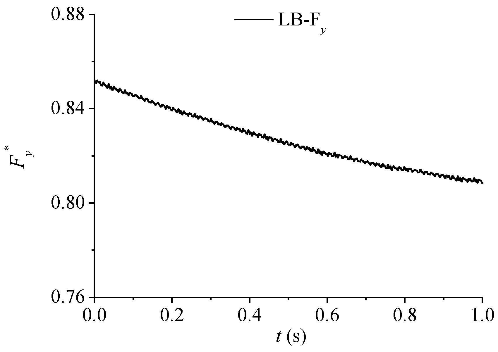
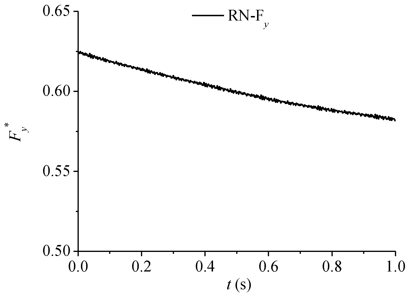
In
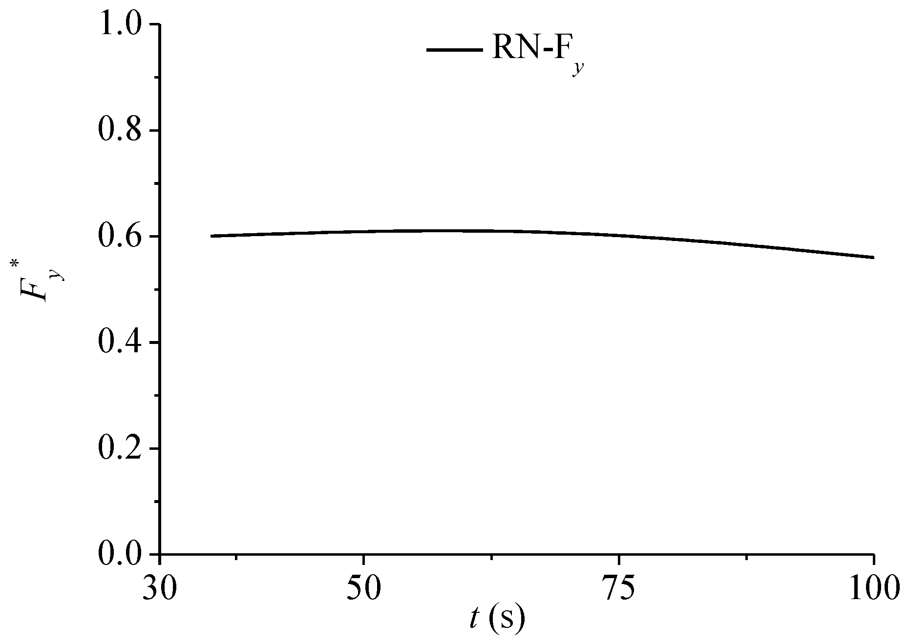
Figure 17, the total axial water thrust of the lower band of the runner is along the positive direction of the Y axis, about 0.82 mg. Combining the axial water thrust of the blades in
Figure 11 and the axial water thrust of the upper crown in
Figure 14, the total water thrust of the runner (RN-F
y) in
Figure 18 is about 0.6 mg. Affected by LB-F
y, it decreased slightly over time.
4. Conclusions
In this paper, the CFD method considering the gap flow and pressure-balance pipe flow of the runner was applied to analyze the internal flow of the pump turbine at the lowest head under no-load condition.
The SST k-ω model was used to predict the three-dimensional internal flow characteristics of pump turbine. The numerical simulation of the efficiency of the unit under different heads was basically consistent with the test results. Considering the energy loss of gap flow, the simulation results of the pump turbine were slightly smaller.
Three working conditions (A, B, C) of no-load process were selected for analysis and comparison. The flow rate, rotation speed, and guide vane opening of the unit under no-load conditions all change within a small range. It can be seen that the main frequency of the monitoring points in the runner under each working condition was basically the same, and the amplitude of pressure pulsation was little different, which was mainly affected by rotor–stator interaction. Among them, the inlet of the runner was close to the guide vane, which was mainly affected by the 22 guide vanes, and there was an obvious 22fn pressure pulsation. The outlet of the runner was far away from the guide vane, which was represented by the rotation frequency of the runner, 1.0fn.
A working condition was selected for the instantaneous internal flow analysis. The speed difference between the pressure surface and the suction surface of the guide vane was relatively large, forming a high-speed ring in the vaneless area. A stable channel vortex was generated in the flow passage near the inlet of the runner. Compared with the axial water thrust of the runner blades BFy, the axial water thrust of the upper crown of the runner (UCI-Fy, UCO-Fy) and the axial water thrust of the lower band of the runner (LBI-Fy, LBO-Fy) were very large, about 560 times of BFy. The BFy, UCI-Fy, UCO-Fy, and LBI-Fy changed periodically. Affected by rotor–stator interaction, it was 22fn. The total axial water thrust of the runner RN-Fy was in the opposite direction of gravity, about 0.6 mg. During the entire no-load process, the axial water thrust of the runner changed slowly with time.


