Article

Investigation of the Dynamic Characteristics of an Eccentric Annular Seal on the Basis of a Transient CFD Method with Three Whirl Models

1
State-Province Joint Engineering Laboratory of Fluid Transmission System Technology, Zhejiang Sci-Tech University, Hangzhou 310018, China
2
Zhejiang Institute of Mechanical & Electrical Engineering Co., Ltd., Hangzhou 310000, China
3
Zhejiang Keer Pump Co., Ltd., Rui’an 325206, China
*
Author to whom correspondence should be addressed.
J. Mar. Sci. Eng. 2021, 9(11), 1290; https://doi.org/10.3390/jmse9111290
Submission received: 15 October 2021 / Revised: 11 November 2021 / Accepted: 16 November 2021 / Published: 19 November 2021
(This article belongs to the Section Ocean Engineering)

Abstract

:
Many annular seals suffer eccentricity because of rotor–stator misalignment or the deflection of a flexible rotor, which has a strong influence on the vibration characteristics and stability of rotating machines. In this article, a transient CFD method based on three whirl models is employed to research the dynamic characteristics of annular seals at various static eccentricities. The influence of the whirl amplitude on the dynamic characteristics of eccentric annular seals are also explored. The results of the transient CFD method are compared with the bulk flow model results and the experimental results. It is shown that the transient CFD method possesses high prediction precision for direct damping, with a maximum error of 25%. Negative kyx increases by 166% when the static eccentricity ratio is increased from 0 to 0.5. The dynamic characteristics of the annular seal operating at high static eccentric ratio are sensitive to whirl amplitude, and the model with an amplitude of 1% Cr has great advantages for the prediction of direct virtual-mass, while the model with an amplitude of 10% Cr has great advantages for the prediction of cross-coupled damping.

1. Introduction

Centrifugal pumps are commonly employed in the marine field to transport fluids, and annular seals are the key components of centrifugal pumps to reduce the amount of working medium leaking from the high-pressure area to the low-pressure area through the rotor–stator gap [1,2]. With the development of marine exploration and deep-sea engineering, the research on the performances of annular seals in marine centrifugal pumps has become a hot spot. Although the main role of an annular seal is to restrict leakage flow, the fluid response forces produced by an annular seal have an obvious impact on the stable performance of rotor systems, especially in multistage marine pumps.
Since annular seals have a strong influence on the vibration performance of pump systems, many studies have been carried out on the sealing characteristics and hydraulic forces of annular seals. Childs [3] applied finite-length solutions for the dynamic characteristics of an annular seal on the basis of the bulk flow model put forward by Black. This method has been widely used in engineering [4,5,6] due to its low computational cost and highly efficient computation time. Dietzen and Nordmann [7] first proposed the CFD-perturbation method for smooth-rotor seals to improve the problem of the reliability of the bulk flow model. Then, the method was further developed by Feng [8], Arghir [9] and Kim [10] to make it more appropriate for complicated seal types. With the development of computer techniques and calculation techniques, the three-dimensional CFD method has become an effective method for predicting the static and dynamic characteristics of annular seals. Tam et al. [11] first proposed a quasi-steady CFD method to research the fluid response forces of bearings and seals. The method transforms the transient problem in a stationary frame to a steady one by introducing a multiple reference frame attached to a whirling rotor. Many researchers have carried out numerical analysis into the dynamic characteristics of annular seals using the quasi-steady CFD method [12,13,14,15]. However, the introduction of quasi-steady simplification causes additional errors in the analysis of the dynamic characteristics of annular seals. In addition, the quasi-steady method is not suitable for dealing with the problems of elliptical rotor disturbance and unidirectional simple harmonic vibration. Therefore, a transient CFD method that directly solves the flow field in a stationary frame was first adopted by Williams et al. [16] to determine the changes over time of the fluid response forces acting on the moving wall. Later, Li et al. [17] used the transient CFD method with a unidirectional harmonic (1D) whirl model, a circular whirl model, and an elliptical whirl model to predict the dynamic characteristics of an annular gas seal. It was revealed that the magnitudes of dynamic coefficients of the seal obtained by the three whirl models match very well with the experimental results, and the values of the corresponding dynamic coefficients are almost the same for all rotor whirl models. The transient CFD method with the whirl models was also employed by Voigt [18], Yan et al. [19,20] and Jiang [21] to calculate the dynamic characteristics of annular seals.
The above research on annular seals was focused on seals with a centered position, meaning that the rotor and stator are concentric. However, only under ideal research circumstances is the seal able to operate in a centered state. Actually, the tolerance accumulation of various components, rotor–stator misalignment, and the side load of the impeller cause the actual working state of the seal to be eccentric, which has a strong influence on the vibration characteristics and stable performance of the rotating system [22]. Yang et al. [23] used a finite difference scheme to predict the static and dynamic performance of annular seals under eccentric conditions. The results showed that leakage flowrate was not sensitive to rotor static eccentricity, while cross-coupled stiffness and direct damping increased with increasing static eccentricity. Zhang et al. [24] used a trigonometric series expansion method to perform theoretical research on the tangential airflow force of eccentric seals. It was shown that the tangential airflow force perpendicular to the eccentric direction of the rotor decreased the stability of the rotor system. Li et al. [25,26] adopted the quasi-steady CFD method to research the leakage flowrate and the dynamic characteristics of the annular seal at high rotor eccentricity ratios. It was revealed that the leakage flowrate and static cross-coupled stiffness increased with increasing static eccentricity. Sun et al. [27] applied an elliptical whirl model with the transient CFD method to study the effects of eccentricity on dynamic characteristics and rotor stability of the labyrinth seal. The results showed that equivalent stiffness and equivalent damping decreased with increasing eccentricity, while the aerodynamic work increased with increasing eccentricity, impairing the stable performance of the annular seal.
In the present work, a transient CFD method based on a 1D whirl model, a circular whirl model, and an elliptical whirl model is applied to study the effects of static eccentricities on the dynamic characteristics of an annular seal, and the method is verified on the basis of a comparison between the results obtained using the bulk flow model and the experimental results. Comparisons with different rotor whirl models are also carried out. Then, the effects of the whirl amplitudes on the dynamic characteristics of the annular seal at various static eccentricities are investigated.

2. Numerical Model and Calculation Method

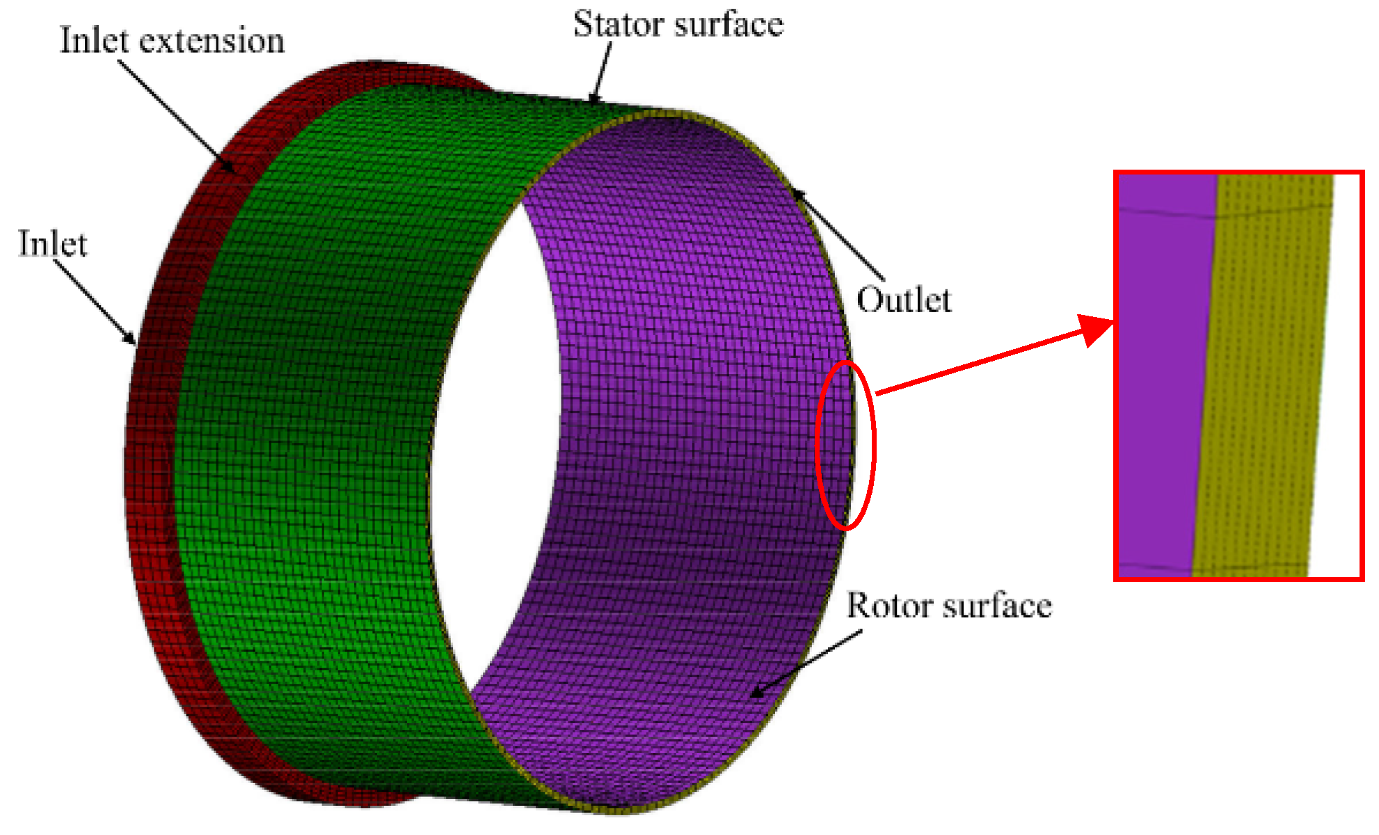
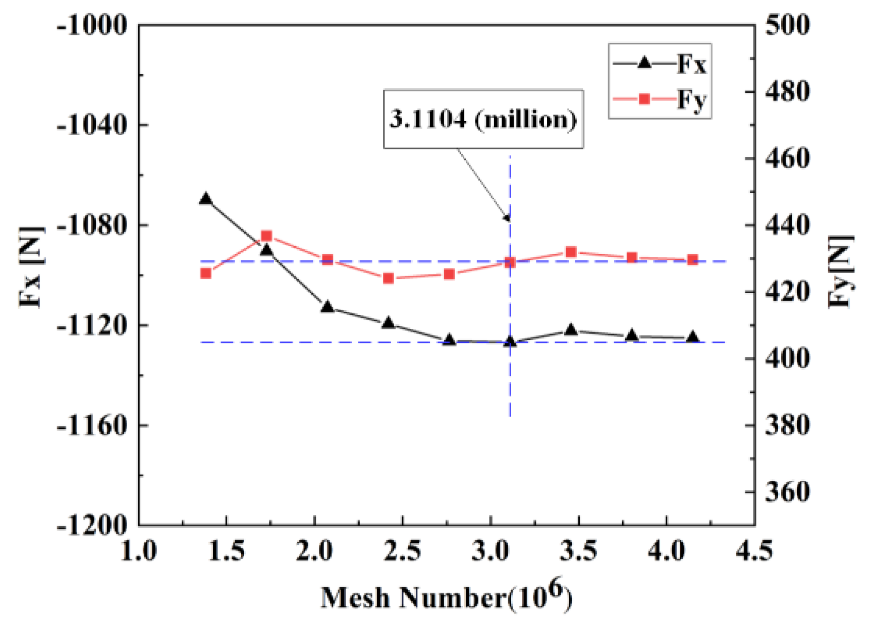
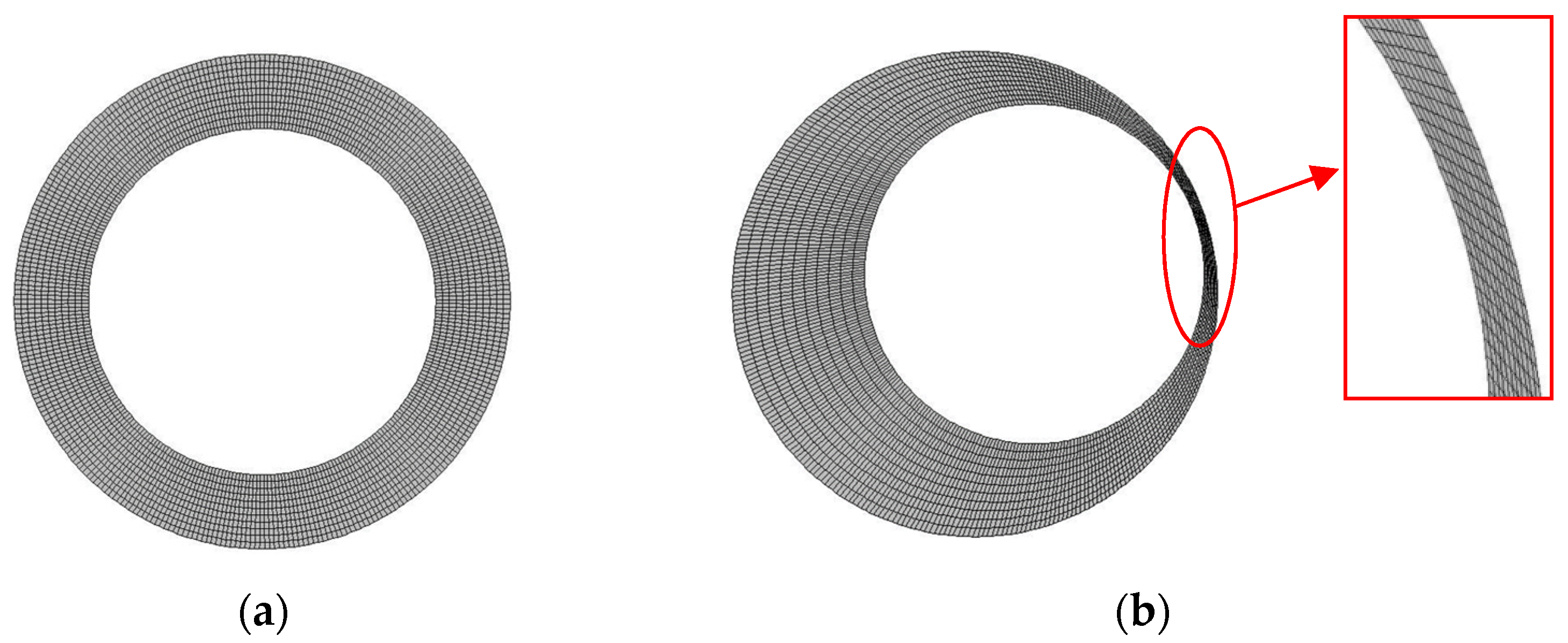
2.1. Geometric Structure and Mesh

The annular seal studied in this paper is based on Marquette’s experimental model [28], which is a liquid annular seal having the characteristic of smooth walls. The main geometrical dimensions and working conditions of the annular seal are listed in Table 1. The whole fluid domain of the annular seal is divided into hexahedral grids, as shown in Figure 1. The grid independence is analyzed by comparing the fluid response forces under different grid densities. As illustrated in Figure 2, when the number of grids is increased to 3.1104 million, the fluid response forces Fx and Fy nearly remain constant. Thus, the present grid number of 3.1104 million is selected for further numerical calculations.

2.2. Identification Method of Seal Dynamic Coefficients

With regard to small perturbations of the rotor around eccentric positions, fluid response forces (Fx, Fy) are defined as the linearized dynamic form [29], which is presented in Equation (1). In this paper, a two-degrees-of-freedom spring mass model is selected to describe the whirling trajectory of the rotor, and the whirling displacement signal is applied in two mutually perpendicular directions (X direction and Y direction). When the rotor whirling displacement signal contains only one whirling frequency, there are three types of whirling displacement trajectory of the rotor, i.e., a one-dimensional linear trajectory, a circular trajectory, and an elliptical trajectory [30]. To obtain the dynamic characteristics of the eccentric annular seal, three different rotor whirl models (1D whirl model, circular whirl model and elliptical whirl model) are used as excitation signals to simulate the transient flow field of the annular seal. The mathematical models and schematic diagrams of the whirl models are presented in Equations (2)–(4) and Figure 3, respectively. The rotor is eccentric in the positive X direction and the rotor whirls along the red orbits.
[ F x F y ] = [ k x x ( ε ) k y x ( ε ) k x y ( ε ) k y y ( ε ) ] [ x d y d ] + [ c x x ( ε ) c y x ( ε ) c x y ( ε ) c y y ( ε ) ] [ x d y d ] + [ m x x ( ε ) m y x ( ε ) m x y ( ε ) m y y ( ε ) ] [ x d y d ]
1D whirl model
{ x d = ε + δ sin ( Ω t ) ,   y d = 0   ( X - direction   whirl ) x d = 0 ,   y d = ε + δ sin ( Ω t )   ( Y - direction   whirl )
Circular whirl model
{ x d = ε + e cos ( Ω t ) ,   y d = e sin ( Ω t )   ( Forward   whirl ) x d = ε + e cos ( Ω t ) ,   y d = e sin ( Ω t )   ( Backward   whirl )
Elliptical whirl model
{ x d = ε + a cos ( Ω t ) , y d = b sin ( Ω t )   ( Forward   whirl ) x d = ε + a cos ( Ω t ) , y d = b sin ( Ω t )   ( Backward   whirl )
Substituting whirl Equations (2)–(4) into Equation (1), the fluid response forces (Fx, Fy) are redefined as simple harmonic functions with respect to time, as shown in Equation (5).
{ F x = F x 0 + a 11 cos ( Ω t ) + a 12 sin ( Ω t ) F y = F y 0 + a 21 cos ( Ω t ) + a 22 sin ( Ω t )
Fx0 and Fy0 denote the fluid force of the rotor in a static eccentric position. a 11 = b 1 k x x b 2 c x y Ω + b 1 m x x Ω 2 , a 12 = b 2 k x y + b 1 c x x Ω + b 2 m x y Ω 2 , a 21 = b 1 k y x b 2 c y y Ω + b 1 m y x Ω 2 , a 22 = b 2 k y y + b 1 c y x Ω + b 2 m y y Ω 2 . b1 and b2 in the 1D whirl model, the circular whirl model and the elliptical whirl model are different, i.e., in the x-direction whirl, b1-1D = δ, b2-1D = 0, and in the y-direction whirl, b1-1D = 0, b2-1D = δ; b1-circle = b2-circle = e and b1-ellipse = a, b2-ellipse = b = 0.5a. The time-varying Fx and Fy acting on the rotor surface can be determined by integrating pressure and shear stress on the rotor surface at each time step. Then, based on curve fitting, the fluid response forces (Fx, Fy) are employed to evaluate values of Fx0, Fy0 and coefficients (a11, a12, a21 and a22) of trigonometric functions. There exists one known whirl speed and three unknown dynamic coefficients in a11, a12, a21 and a22. Therefore, at least 3 transient CFD runs should be carried out to solve all the unknown dynamic coefficients. Generally, mxy and myx are very small, and are treated as zero.
Figure 3. The schematic diagram of the whirl models: (a) 1D whirl model; (b) circular whirl model; (c) elliptical whirl model.
Jmse 09 01290 g003

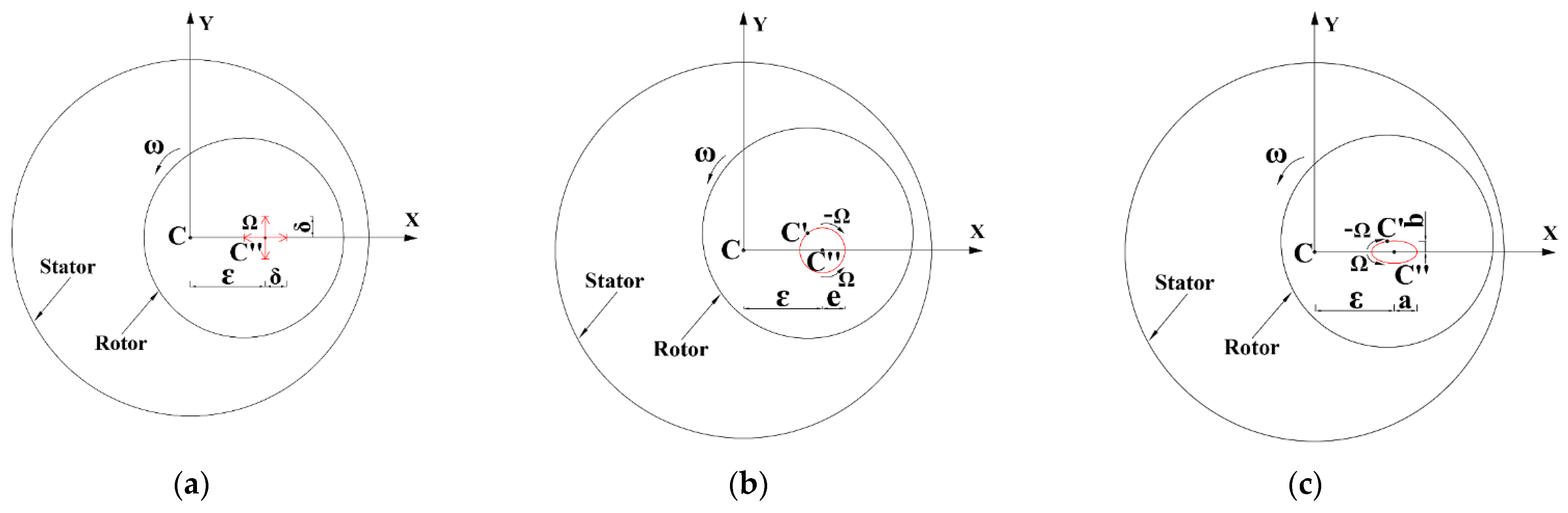
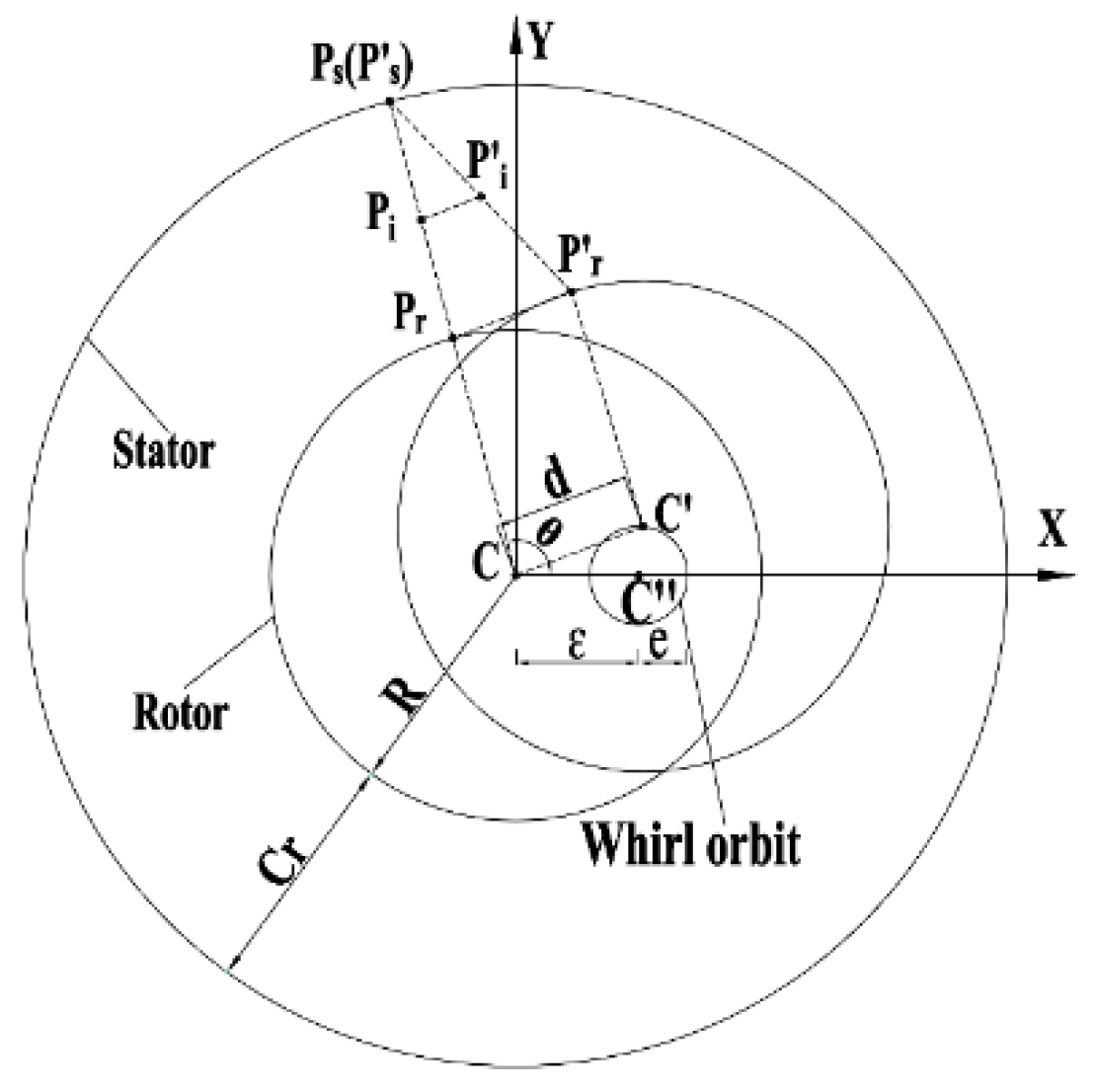
2.3. The Motion of Mesh

The whirling movement of the rotor leads to the fluid field of the annular seal changing over time, which requires a mesh morphing technique to handle. In the present paper, the mesh morphing technique is realized through user-defined subroutines connected with a solver to calculate and control the movement of all nodes in fluid domain. For the sake of brevity, only the circular whirl model is used to act as an instance to illustrate the movement of grid nodes [21]. The specific implementation details are as follows.
Figure 4 illustrates the movement of grid nodes on any axial section of the annular seal. As shown in the figure, Pr (xr, yr) and Ps (xs, ys) are nodes on the moving wall and stationary wall when the rotor is at a homocentric position, marked C. The node Pi (xi, yi) is any point in the clearance along the mesh line of PsPr, and θ represents the initial angular displacement of Pi. C’ stands for the present eccentric position of the rotor after moving from the position of C, and the movement displacement is denoted by d (xd, yd). Subsequently, the node coordinates (xr′, yr′) of P′r on the rotor surface are obtained with Equation (6).
x r = x r + x d , y r = y r + y d
When the rotor moves, the nodes on the stator surface remain stationary and the movement displacements of the nodes in the clearance are determined by interpolation algorithm [21]. Subsequently, the coordinates (xi′, yi′) of P′i in the clearance are achieved as shown in Equation (7).
x i = x i + S c × x d , y i = y i + S c × y d
where Sc represents the ratio of the distance between the nodes in the clearance and the outer wall to the clearance. The rotor and the stator are in a concentric state, so Sc can be expressed by the coordinates (xi, yi) of Pi. When there is eccentricity between the stator and the rotor, Sc can be expressed by the known coordinates (xi′, yi′) of the P′i, the movement displacement d of the rotor, and the initial angular displacement θ of Pi. Then Sc is substituted into Equation (7) to obtain the next position of the node P′i in the clearance after the rotor moves.
The grid displacements of the annular seal are calculated through the mesh morphing procedure to guarantee the harmony of the movement of adjacent grid nodes. To test the feasibility of the algorithm, the rotor is whirled from the concentric state (Figure 5a) to a state with an eccentricity of 0.8 (Figure 5b), and it is found that the grid distortion becomes larger, but there exist no highly distorted grid cells and negative volumes. For the mesh morphing technique, the amount of change in the coordinate of the node in the gap is inversely proportional to the distance from the rotor to control the minimum distortion of the mesh during the whirl [31]. The connections between the nodes are similar to springs, and the number of nodes and the connection properties between the nodes remain unchanged at each time step. Due to rotor whirling, the grid cells on one side are compressed, and the cells on the other side are stretched, resulting in an increase in the maximum length–width ratio q on the basis of concentric position, which decreases the grid quality. When the annular seal possesses an eccentricity of 0.8, the maximum of length–width ratio is no more than 200 based on q = q0/(1 − εe) [21]. Therefore, the mesh morphing technique is appropriate for transient numerical calculations of eccentric annular seals.

2.4. Calculation Method

Fluent 16.0 is adopted to solve the three-dimensional flow field of the eccentric annular seal. The working fluid is water at a temperature of 20 °C. The boundary conditions at the inlet and outlet are given as total pressure (6.89 MPa) and static pressure (0 MPa), respectively. Rotor surface (moving wall) and stator surface (stationary wall) are set as nonslip walls. The rotation speed of the moving surface is given by DEFINE_ PROFILE, and the whirl speed of the moving surface are determined through macro DEFINE_GRID_MOTION. Since the wall Y+ is less than 2.5, the turbulence of the realizable k-ε model with enhanced wall treatment is selected [32]. A first-order implicit scheme is adopted to discretize the time term, and the time increment is 1.63 × 10⁻⁵ s, i.e., the rotor rotates one degree. Second-order upwind schemes and central difference schemes are employed to discretize the convection term and diffusion term, respectively. The velocity–pressure coupling is handled by the SIMPLE algorithm.

3. Results

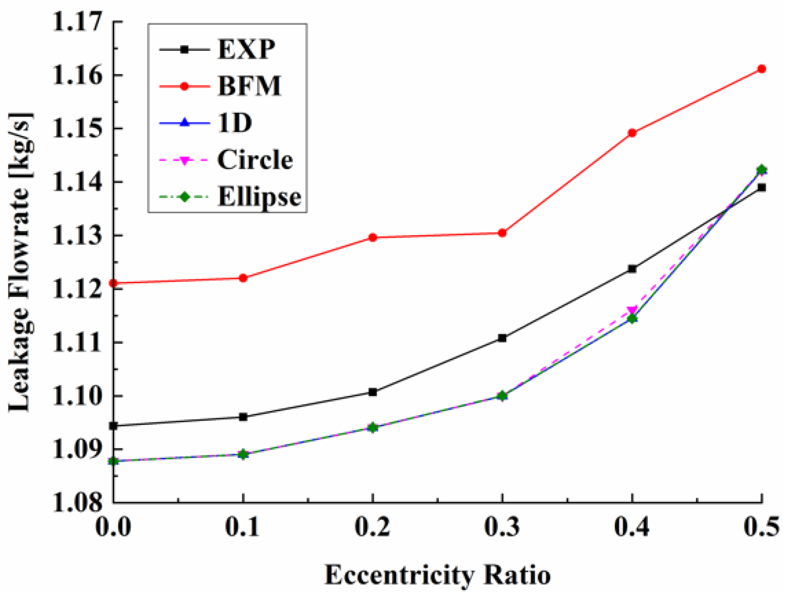
3.1. Theoretical and Experimental Verification

Figure 6 presents a comparison of the leakage flowrates predicted by the transient CFD method based on three whirl models with the bulk flow model results and the experimental results [28]. In the present simulations, the whirl amplitude is determined as 1% of Cr. The leakage flowrates from the 1D whirl model, circular whirl model and elliptical whirl model are almost the same. The maximum error of the transient simulation is 0.97%, which is lower than that of the bulk flow model. As shown in the figure, the leakage flowrates of the experiment increase slightly as static eccentricity increases. The variation trend of the transient CFD simulation method is more consistent with the experimental one than the trend of the bulk flow model is. Therefore, the transient CFD method is more applicable for predicting the leakage flowrates of annular seals.
Figure 7 presents a comparison of the dynamic characteristics predicted by the transient CFD method with three whirling models with the results of the bulk flow method and the experimental results [28]. For the transient CFD method, the results show that the error of the direct damping coefficients is the smallest (the maximum error is less than 25%), while the error of the direct virtual-mass coefficient (mxx) is the largest (the maximum error is up to 67%). Since the annular seal under study is a short annular seal, direct virtual-mass coefficients are small, leading to the transient CFD method having no obvious advantage in predicting direct virtual-mass coefficients. Direct stiffness coefficients and cross-coupled stiffness coefficients are underpredicted by the transient CFD method, and their prediction accuracy is slightly worse than that of the bulk flow method. This is due to the current numerical model ignoring the influence of the non-uniform of upstream flow of the annular seal, which is not consistent with the practical non-uniformity in the experiment. The direct damping coefficients predicted by the transient CFD method are larger than the experimental results, while the cross-coupled damping coefficients of the method are smaller than the experimental results. However, the accuracy of the present CFD method in predicting direct damping and cross-coupled damping is superior to that of the bulk flow model. As for direct virtual-mass coefficients, when static eccentricity is less than 0.4, the results of the transient CFD method are almost larger than the experimental results, but its prediction accuracy is higher than that of the bulk flow model. When static eccentricity is more than 0.4, the accuracy of the CFD method with the circular whirling model and the elliptical whirling model is also superior to that of the bulk flow method. In general, as the high-precision prediction of damping coefficients is more difficult than that of stiffness coefficients, and damping coefficients have an important influence on the stability of high-speed long shaft system. Therefore, the transient CFD method with three whirl models, which has better ability in damping prediction, is used in the present paper.

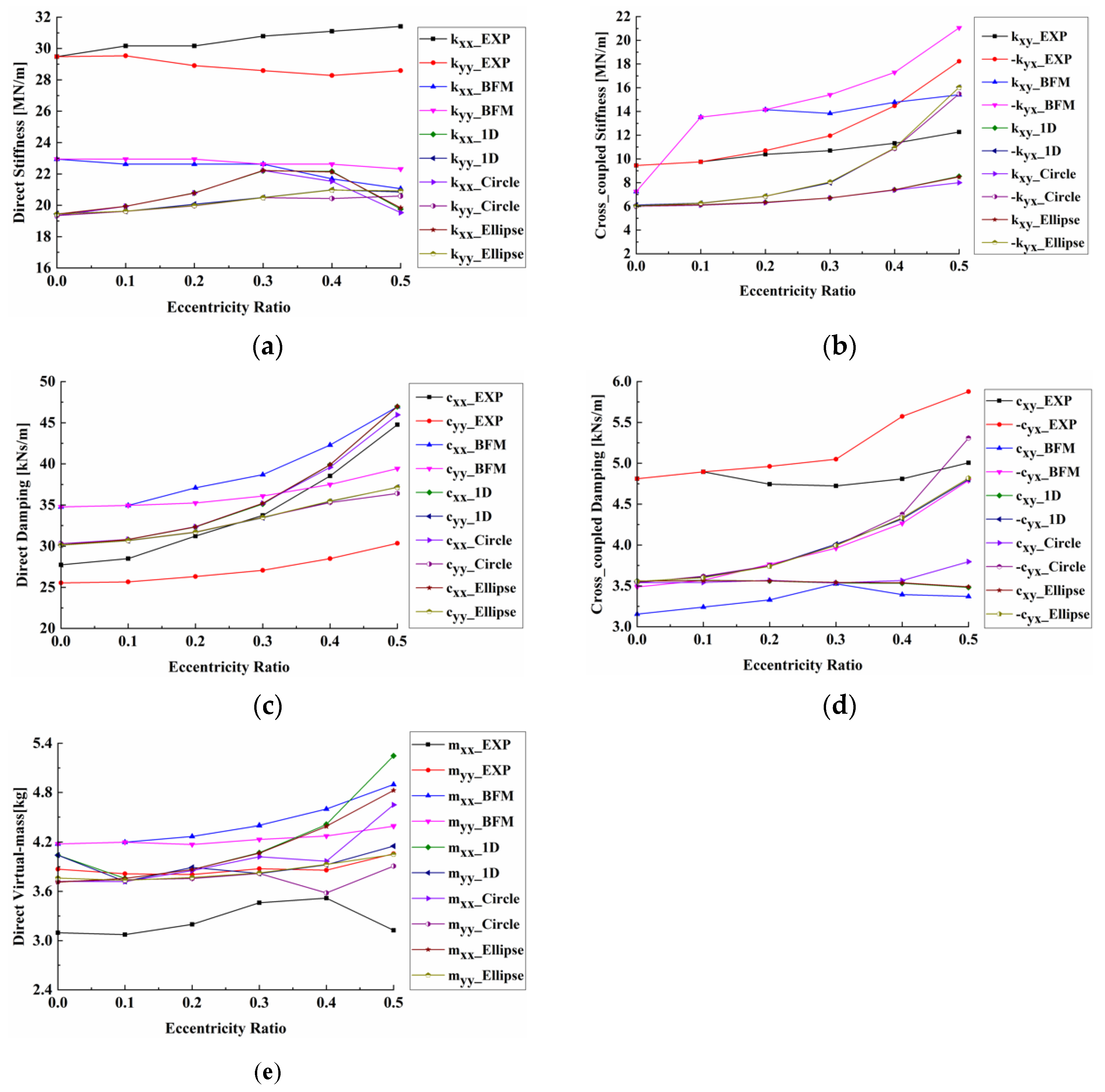
3.2. Effects of Static Eccentricities and Whirl Models on the Dynamic Characteristics of the Annular Seal

Figure 7 shows that, as static eccentricity increases, the dynamic characteristics gradually deviate from the results of the concentric seal (εe = 0), and the dynamic coefficients no longer have the characteristics of equal main terms and negative cross terms (for example, kxx is not equal to kyy, and kxy is not equal to −kyx). The stiffness coefficients (kyy, kxy and −kyx) and damping coefficients (cxx, cyy and −cyx) of the three whirl models increase as static eccentricity increases. When static eccentricity is increased from 0 to 0.5, the maximum growth amplitudes of kyy, kxy and −kyx among the three whirl models are 7.6%, 42% and 166%, respectively, and the maximum amplitudes of cxx, cyy and −cyx among the three whirl models are 56%, 23% and 50%, respectively. With increasing static eccentricity, the kxx of the three whirl models first increases and then decreases. As static eccentricity increases, the cxy of the circular whirl model first decreases and then increases, while the cxy of the 1D whirl model and the elliptical whirl model decreases across the whole range of static eccentricities. As for direct virtual-mass coefficients (mxx, myy), the three whirl models all increase with increasing static eccentricity, except that the circular whirl model decreases when static eccentricity is between 0.3 and 0.4.
It also shows that the whirl model has almost no influence on the stiffness coefficients (kxx, kyy, kxy, −kyx) and the damping coefficients (cxx, cyy, cxy, −cyx) if the rotor whirls around static eccentricity that is less than 0.4. However, when static eccentricity is more than 0.4, the stiffness coefficients and the damping coefficients are sensitive to whirl model. As shown in Figure 7a–c, predictions of the circular whirl model for direct stiffness coefficients, cross-coupled stiffness coefficients and direct damping coefficients are smaller than those of the 1D whirl model and the elliptical whirl model. The accuracy of the direct stiffness coefficients and cross-coupled stiffness coefficients predicted by the circular whirl model is slightly worse than those of the other two whirl models, but the prediction accuracy for the direct damping coefficients is better than those of the other two whirl models. As illustrated in Figure 7d, the predictions of the circular whirl model for the cross-coupled damping coefficients are obviously greater than those of the 1D whirl model and the elliptical whirl model, which are well matched with the experimental results. It also can be observed that the trend of the circular whirl model is similar to the experimental plot, and it is superior to the 1D whirl model and the elliptical whirl model. As shown in Figure 7e, the whirl model has almost no effect on direct virtual-mass coefficients when static eccentricity ranges from 0.1 to 0.3. When static eccentricity is less than 0.1 and more than 0.3, direct virtual-mass coefficients are affected by the whirl model. The 1D whirl model possesses the largest direct virtual-mass coefficients, followed by the elliptical whirl model and then the circular whirl model. However, the direct virtual-mass coefficients of the circular whirl model are closer to the experimental data than those obtained by the other two whirl models. In general, achieve the optimal prediction accuracy of damping and correctly capture the trends of damping changing with static eccentricity, the circular whirl model is chosen for further study.

3.3. Effects of Whirl Amplitudes on the Dynamic Characteristics of the Annular Seal at Various Static Eccentricities

The dynamic characteristics of the annular seal shown in Figure 7 are obtained when the rotor whirl amplitude is 1% of Cr. Figure 8 shows that the other two rotor whirl amplitudes (5% of Cr and 10% of Cr) of the circular whirl model are employed to calculate the dynamic characteristics of the eccentric annular seals. It can be seen that when the static eccentricity is less than 0.3, the dynamic characteristics of the three whirl amplitudes almost coincide. Then, with increasing static eccentricity, different whirl amplitudes provide different results, and these are compared with the experimental data. It is shown that the model with whirl amplitude of 1% Cr is good for predicting direct damping coefficients and direct virtual-mass coefficients, while it is bad for predicting cross-coupled stiffness coefficients. The model with amplitude of 5% Cr is helpful for the prediction of direct stiffness coefficients, but is not suitable for the prediction of cross-coupled damping coefficients. The whirl amplitude with 10% Cr has advantages for the prediction of cross-coupled damping coefficients, but it has disadvantages for the prediction of direct stiffness coefficients, direct damping coefficients and direct virtual-mass coefficients. Therefore, the analysis results reveal that whirl amplitude has a great influence on the dynamic characteristics of large eccentric annular seals.

4. Conclusions

A transient CFD method is adopted in this paper to study an annular seal with various static eccentricities, and which is suitable when using 1D whirl models, circular whirl models, and elliptical whirl models as the excitation signal to calculate the dynamic characteristics of the annular seal. The method is validated by the bulk flow model results and the experimental results. The effects of the static eccentricities and whirl amplitudes on the dynamic characteristics of the seal are discussed. The following conclusions can be drawn.
  • The mesh morphing technique implemented by user-defined subroutines can update the grids in the clearance of the annular seal with the rotation of the rotor whirl at each time step, and the grids in the gap of the annular seal are without highly deformed grid cells and negative volume.
  • The three whirl models of the transient CFD method demonstrate great improvement compared to the bulk flow model for the prediction of direct damping coefficients and cross-coupled damping coefficients, and the three whirl models have the highest prediction accuracy for direct damping coefficients, with a maximum error of 25%. Compared with the 1D whirl model and the elliptical whirl model, the circular whirl model is the best choice for obtaining high-precision damping and correctly capturing the trends of damping changing with static eccentricity.
  • As static eccentricity increases, the dynamic characteristics coefficients of the eccentric annular seal are no longer characteristics with equal main terms and negative cross terms. Negative kyx increases significantly with increasing static eccentricity, and it increases by 166% when static eccentricity is increased from 0 to 0.5.
  • Whirl amplitude has an obvious influence on the dynamic characteristics of eccentric annular seal when the static eccentricity is greater than 0.3, and 1% of Cr and 10% of Cr have great advantages when predicting direct virtual-mass and cross-coupled damping, respectively.

Author Contributions

Conceptualization, L.Z.; methodology, L.Z.; validation, B.C., J.G. and G.C.; formal analysis, F.L.; writing—review and editing, F.L. All authors have read and agreed to the published version of the manuscript.

Funding

This research was funded by the National Natural Science Foundation of China (Grant No. 51976199 and Grant No. U1709209), Key Research and Development Program of Zhejiang Province (Grant No. 2020C01027), and Zhejiang Province High-level Talent Special Support plan (2019R51002).

Institutional Review Board Statement

Not applicable.

Informed Consent Statement

Not applicable.

Data Availability Statement

Not applicable.

Conflicts of Interest

The authors declare no conflict of interest.

Nomenclature

aThe major axis of elliptical whirl orbit (mm)
bThe minor axis of elliptical whirl orbit (mm)
BFMBulk flow model
CFDComputational fluid dynamics
CThe center of stator
C’The center of rotor
C”The static eccentric position
CrSeal clearance (mm)
cxx, cyyDirect damping (Ns/m)
cxy, cyxCross-coupled damping (Ns/m)
dThe movement displacement of the rotor when moving from the concentric position to the eccentric position (m)
eCircular whirl amplitude (mm)
EXPExperiment
FxFluid response force in x direction due to x direction excitation (N)
FyFluid response force in y direction due to y direction excitation (N)
Fx0Fluid response force in x direction due to rotor static eccentricity (N)
Fy0Fluid response force in y direction due to rotor static eccentricity (N)
kxx, kyyDirect stiffness (N/m)
kxy, kyxCross-coupled stiffness (N/m)
LSeal length (mm)
mxx, myyDirect virtual-mass (kg)
mxy, myxCross virtual-mass (kg)
PDPressure difference (MPa)
qThe maximum length–width ratio of grids when the rotor is in eccentric position
q0The maximum length–width ratio of grids when the rotor is in concentric position
RSeal radius (mm)
ScThe ratio of the distance between the nodes in the clearance and the outer wall to the clearance
xdRelative rotor to stator displacement in x direction (m)
ydRelative rotor to stator displacement in y direction (m)
θInitial angular displacement of Pi (rad)
εEccentricity (mm)
εeEccentricity ratio (ε/Cr)
δ1D whirl amplitude (mm)
ωSpinning speed (rpm)
ΩWhirl speed (rpm)

References

  1. Lakshminarayana, B. Fluid Dynamics and Heat Transfer of Turbomachinery; John Wiley and Sons: New York, NY, USA, 1996; p. 339. [Google Scholar]
  2. Chupp, R.E.; Hendricks, R.C.; Lattime, S.B.; Steinetz, B.M. Sealing in turbomachinery. J. Propul. Power 2006, 22, 313–349. [Google Scholar] [CrossRef]
  3. Childs, D.W. Finite-length solutions for rotordynamic coefficients of turbulent annular seal. J. Tribol. 1983, 105, 437–444. [Google Scholar] [CrossRef]
  4. Kim, C.H.; Childs, D.W. Analysis for rotordynamic coefficients of helically-grooved turbulent annular seals. J. Tribol. 1987, 109, 136–143. [Google Scholar] [CrossRef]
  5. Zhai, L.L.; Zhang, Z.J.; Chi, Z.H.; Guo, J. Dynamic analysis of liquid annular seals with herringbone grooves on the rotor based on the perturbation method. R. Soc. Open Sci. 2018, 5, 180101. [Google Scholar] [CrossRef] [PubMed] [Green Version]
  6. Xia, P.; Liu, Z.S.; Yu, X.Y.; Zhao, J.M. A transient bulk flow model with circular whirl motion for rotordynamic coefficients of annular seals. Chinese J. Aeronaut. 2018, 31, 1085–1094. [Google Scholar] [CrossRef]
  7. Dietzen, F.J.; Nordmann, R. Calculating rotordynamic coefficients of seals by finite-difference techniques. J. Tribol. 1987, 109, 388–394. [Google Scholar] [CrossRef] [Green Version]
  8. Feng, T.; Nordmann, R. Identification of fluid-structure interactions in centrifugal pumps (Part 1: Computational procedure). In Proceedings of the ISROMAC-4, Honolulu, HI, USA, 5–8 April 1992; 1992; pp. 34–43. [Google Scholar]
  9. Arghir, M.; Frene, J. Forces and moments due to misalignment vibrations in annular liquid seals using the averaged navier-stokes equations. J. Tribol. 1997, 119, 279–287. [Google Scholar] [CrossRef]
  10. Kim, N.; Rhode, D.L. A new CFD-perturbation model for the rotordynamics of incompressible flow seals. In Proceedings of the ASME Turbo Expo 2000: Power for Land, Sea and Air, Munich, Germany, 8–11 May 2000; pp. 1–9. [Google Scholar]
  11. Tam, L.T.; Przekwas, A.J.; Muszynska, A.; Hendricks, R.C.; Braun, M.J.; Mullen, R.L. Numerical and analytical study of fluid dynamic forces in seals and bearings. J. Vib. Acoust. 1988, 110, 315–325. [Google Scholar] [CrossRef]
  12. Subramanian, S.; Sekhar, A.S.; Prasad, B.V. Rotordynamic characteristics of rotating labyrinth gas turbine seal with centrifugal growth. Tribol. Int. 2016, 97, 349–359. [Google Scholar] [CrossRef]
  13. Moore, J.J. Three-dimensional CFD rotordynamic analysis of gas labyrinth seals. J. Vib. Acoust. 2003, 125, 427–433. [Google Scholar] [CrossRef]
  14. Pugachev, A.O.; Degen, H. CFD-predicted rotordynamic coefficients for a 20-teeth-on-stator labyrinth seal at high supply pressure conditions. In Proceedings of the ASME Turbo Expo 2012: Turbine Technical Conference and Exposition, Copenhagen, Denmark, 11–15 June 2012; pp. 1–11. [Google Scholar]
  15. Rao, J.S.; Saravanokumar, M. Numerical simulation of seal flow and determination of stiffness and damping coefficient. In Proceedings of the 7th IFToMM-Conference on Rotor Dynamic, Vienna, Austria, 25–28 September 2006; pp. 25–28. [Google Scholar]
  16. Williams, M.; Chen, W.; Brozowski, L.; Eastland, A. Three-dimensional finite difference method for rotordynamic fluid forces on seals. AIAA J. 1997, 35, 1417–1420. [Google Scholar] [CrossRef]
  17. Li, Z.G.; Li, J.; Feng, Z.P. Comparisons of rotordynamic characteristics predictions for annular gas seals using the transient computational fluid dynamic method based on different single-frequency and multifrequency rotor whirling models. J. Tribol. 2015, 138, 011701. [Google Scholar] [CrossRef]
  18. Voigt, A.J.; Ludiciani, P.; Nielsen, K.K.; Santos, I.F. CFD applied for the identification of stiffness and damping properties for smooth annular turbomachinery seals in multiphase flow. In Proceedings of the ASME Turbo Expo 2016: Turbomachinery Technical Conference and Exposition GT2016, Seoul, Korea, 13–17 June 2016; pp. 1–11. [Google Scholar]
  19. Yan, X.; Li, J.; Feng, Z.P. Investigations on the rotordynamic characteristics of a hole-pattern seal using transient CFD and periodic circular orbit model. J. Vib. Acoust. 2011, 133, 041007. [Google Scholar] [CrossRef]
  20. Yan, X.; He, K.; Li, J.; Feng, Z.P. Rotordynamic performance prediction for surface-roughened seal using transient computational fluid dynamics and elliptical orbit model. J. Power Energy 2012, 226, 975–988. [Google Scholar] [CrossRef]
  21. Jiang, X.K. Transient CFD Simulation on the Flow Field and Dynamic Characteristics of Annular Seals. Ph.D. Thesis, Zhejiang University, Hangzhou, China, 2016. [Google Scholar]
  22. Childs, D.W.; Arthur, S.P. Static destabilizing behavior for gas annular seals at high eccentricity ratios. In Proceedings of the ASME Turbo Expo 2013: Turbine Technical Conference and Exposition GT2013, San Antonio, TX, USA, 3–7 June 2013; pp. 1–7. [Google Scholar]
  23. Yang, Z.; San Andres, L.; Childs, D.W. Dynamic force performance of annular gas seals at off-center conditions. Tribol. T. 1994, 37, 33–42. [Google Scholar] [CrossRef]
  24. Zhang, W.F.; Yang, J.G.; Cao, H.; Guo, R.; Sun, D. Theoretical and experimental research of tangential fluid-induced force and its influence on stability in eccentric seal. J. Mech. Eng. 2011, 47, 92–98. [Google Scholar] [CrossRef]
  25. Li, Z.G.; Chen, Y.X.; Li, J. Investigation on the leakage and static dynamic characteristics of rotating seals at high eccentricity ratios. J. Xi’an Jiaotong Univ. 2017, 51, 1–7. [Google Scholar]
  26. Li, Z.G.; Li, J.; Feng, Z.P. Numerical investigation on the leakage and static stability characteristics of pocket damper seals at high eccentricity ratios. J. Eng. Gas Turbines Power 2017, 140, 042503. [Google Scholar] [CrossRef]
  27. Sun, D.; Lu, J.; Ai, Y.T.; Zhou, H.L.; Wang, Z. Dynamical characteristics of eccentric seal and novel floating self-adapt concentric seal concepts. J. Propul. Technol. 2018, 39, 2075–2084. [Google Scholar]
  28. Marquette, O.R.; Childs, D.W.; San Andres, L. Eccentricity effects on the rotordynamic coefficients of plain annular seals: Theory Versus experiment. J. Tribol. 1997, 119, 443–447. [Google Scholar] [CrossRef]
  29. Nelson, C.C.; Nguyen, D.T. Analysis of eccentric annular incompressible seals: Part 1—A new solution using fast fourier transforms for determining hydrodynamic force. J. Tribol. 1988, 110, 354–359. [Google Scholar] [CrossRef]
  30. Li, Z.G. Investigations on the Leakage Flow and Rotordynamic Characteristics of the Pocket Damper Seal. Ph.D. Thesis, Xi’an Jiaotong University, Xi’an, China, 2017. [Google Scholar]
  31. Li, Q.; Liu, S.L.; Yu, G.C.; Pan, X.H.; Zheng, S.Y. Lubrication and stability analysis of nonlinear rotor-bearing system. J. Zhejiang Univ. 2012, 46, 1729–1736. [Google Scholar]
  32. ANSYS Fluent 16.0. Theory Guide [CP/DK]; ANSYS Inc.: Canonsburg, PA, USA, 2011.
Figure 1. The grid of the annular seal.
Jmse 09 01290 g001
Figure 2. Grid independence analysis.
Jmse 09 01290 g002
Figure 4. Moving diagram of grid nodes.
Jmse 09 01290 g004
Figure 5. The mesh at the radial clearance of annular seal: (a) concentric state; (b) eccentric state.
Jmse 09 01290 g005
Figure 6. Comparison of leakage flowrates of the transient CFD method based on three whirl models with the results of the bulk flow model and the experimental results.
Jmse 09 01290 g006
Figure 7. Comparison of the dynamic characteristics of the transient CFD method based on three whirl models with the bulk flow model results and the experimental results: (a) direct stiffness; (b) cross-coupled stiffness; (c) direct damping; (d) cross-coupled damping; (e) direct virtual-mass.
Jmse 09 01290 g007
Figure 8. Dynamic characteristics of the seal under different whirl amplitudes: (a) direct stiffness; (b) cross-coupled stiffness; (c) direct damping; (d) cross-coupled damping; (e) direct virtual-mass.
Jmse 09 01290 g008
Table 1. Main dimensions and working conditions of the annular seal.
ParametersSymbolsValues
Seal radiusR38.145 mm
Seal clearanceCr0.11 mm
Seal lengthL34.93 mm
Static eccentricity ratioεe0, 0.1, 0.2, 0.3, 0.4, 0.5
Spinning speedω10,200 rpm
Pressure differencePD6.89 MPa
L/2R ratio-0.457
Publisher’s Note: MDPI stays neutral with regard to jurisdictional claims in published maps and institutional affiliations.

