
Dynamics Simulation of Grasping Process of Underwater Vehicle-Manipulator System


Abstract
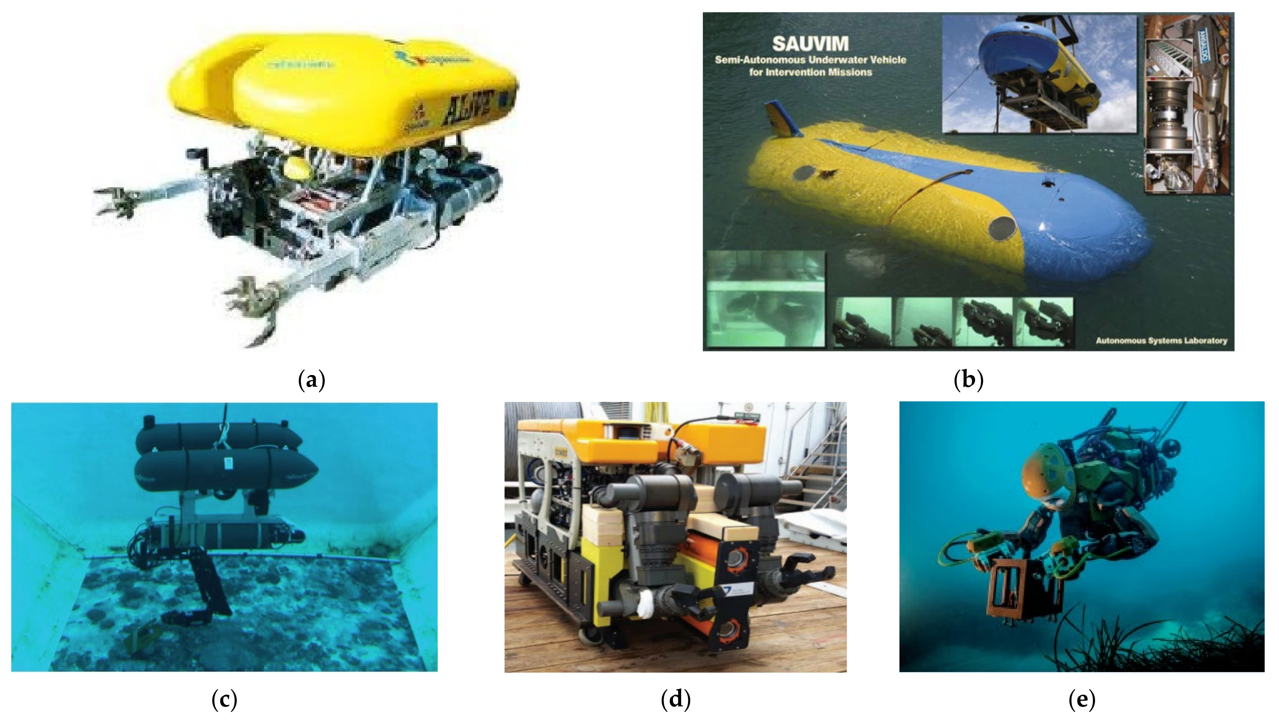
:1. Introduction
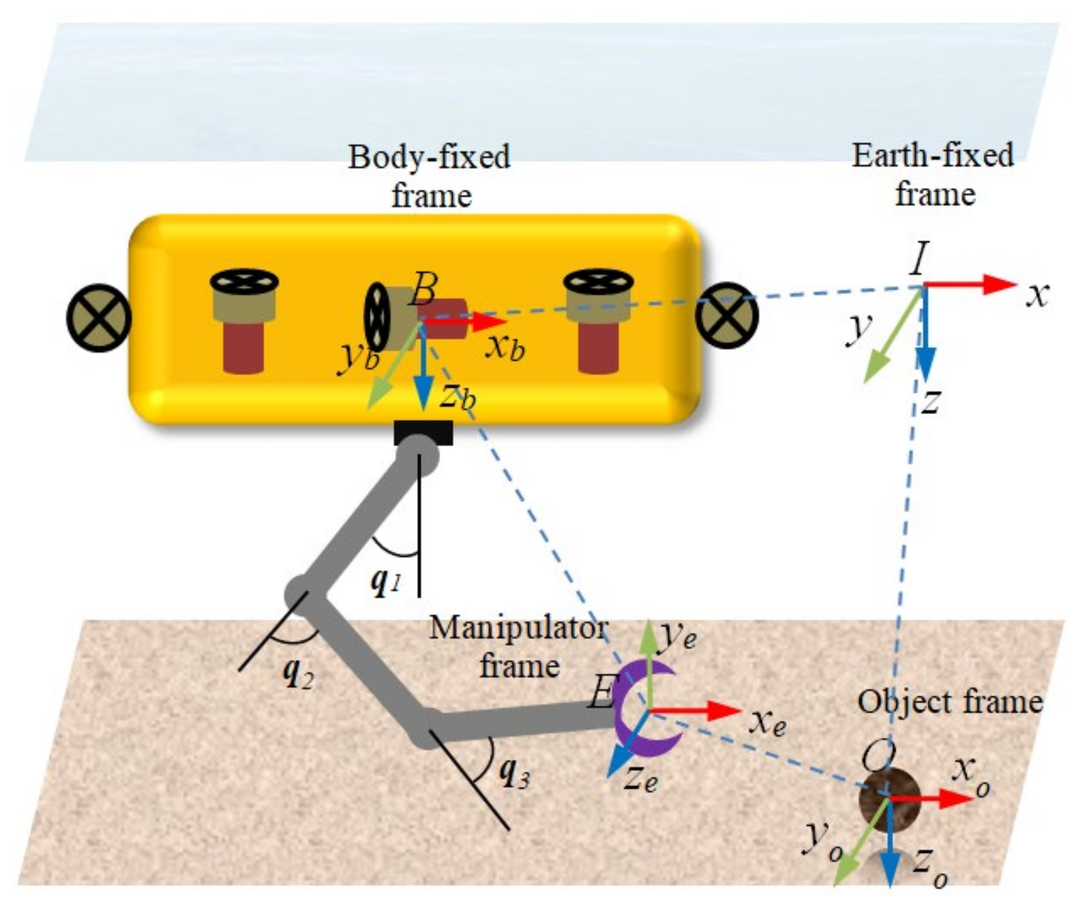
2. Dynamic Modeling of UVMS
2.1. Assumptions
- (1)
- The body of UVMS is fairly symmetrical about its three planes. The center of buoyancy of the vehicle is located on the geometric symmetry plane. The origin of the body-fixed frame is located at the center of buoyancy of the vehicle. The center of gravity (mass) of the vehicle is below its buoyancy center.
- (2)
- The center of buoyancy and gravity of each link of manipulator coincides and is located on its center respectively. It has neutral buoyancy. All the links of manipulator are hinge joint.
- (3)
- There are no ocean current and wave acting on the UVMS and object.
2.2. Kinematic of UVMS
2.3. Dynamic Equation of UVMS
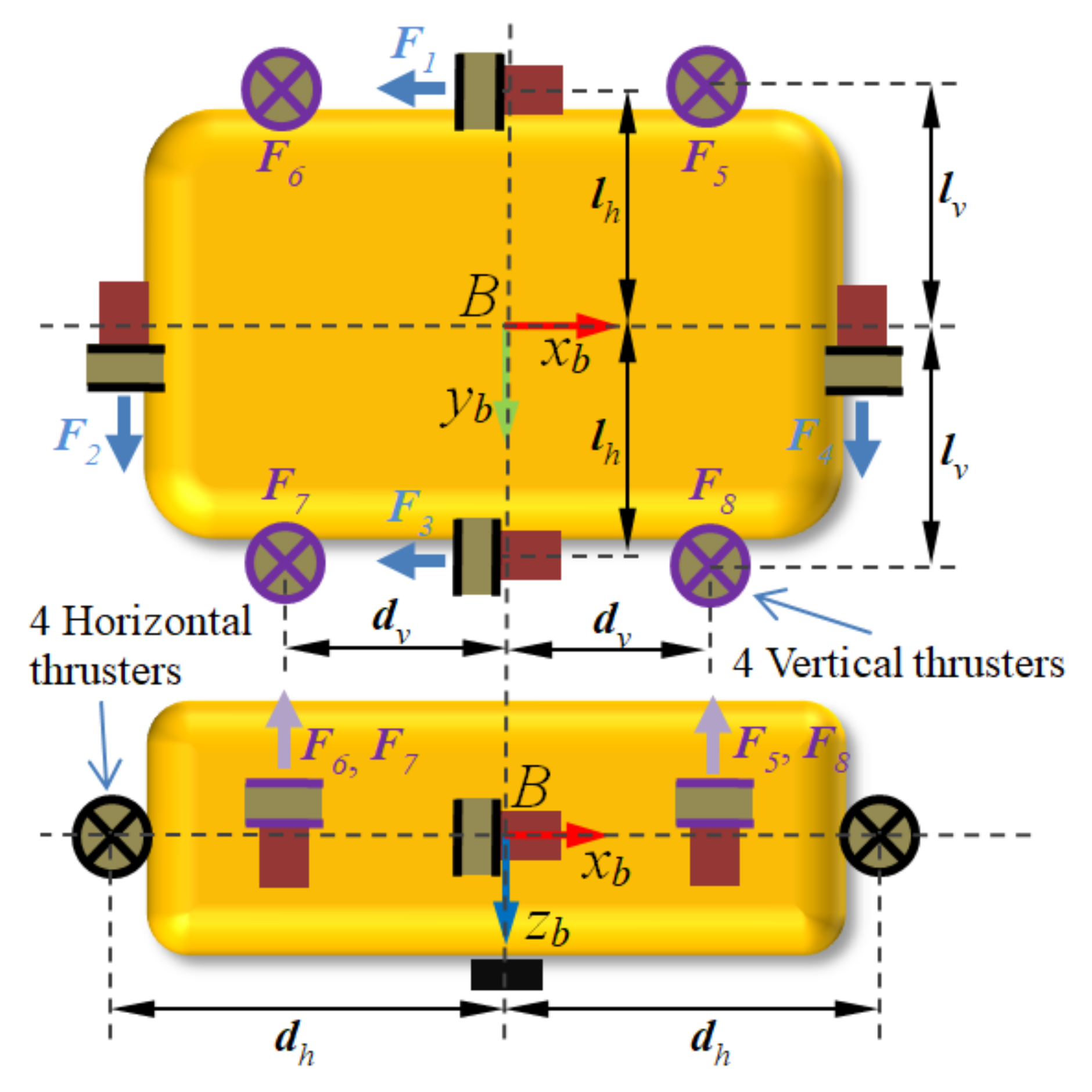
2.4. Configuration of Thrusters
2.5. Contact with Environment
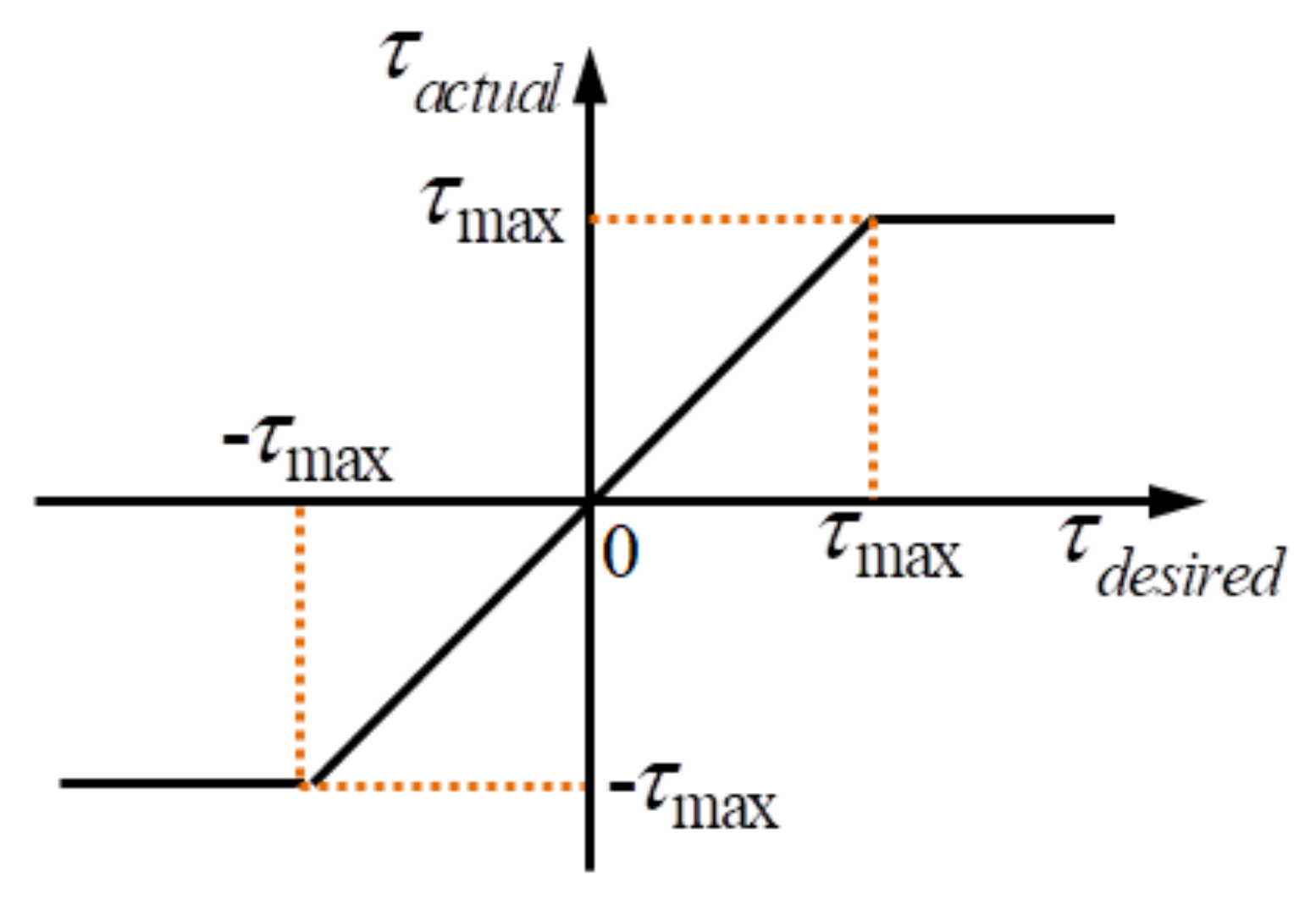
2.6. Actuator Saturation
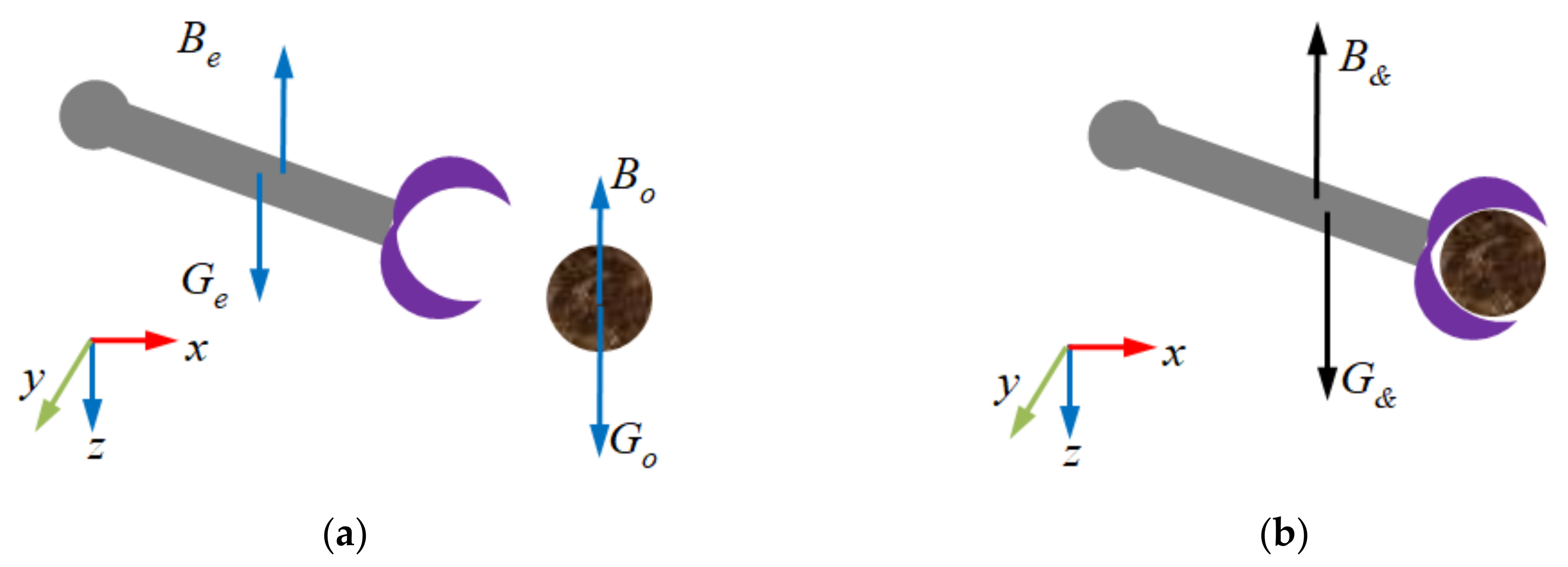
2.7. Modeling of End Effector Carrying an Object
3. Proportional-Integral-Derivative (PID) Control and Parameters
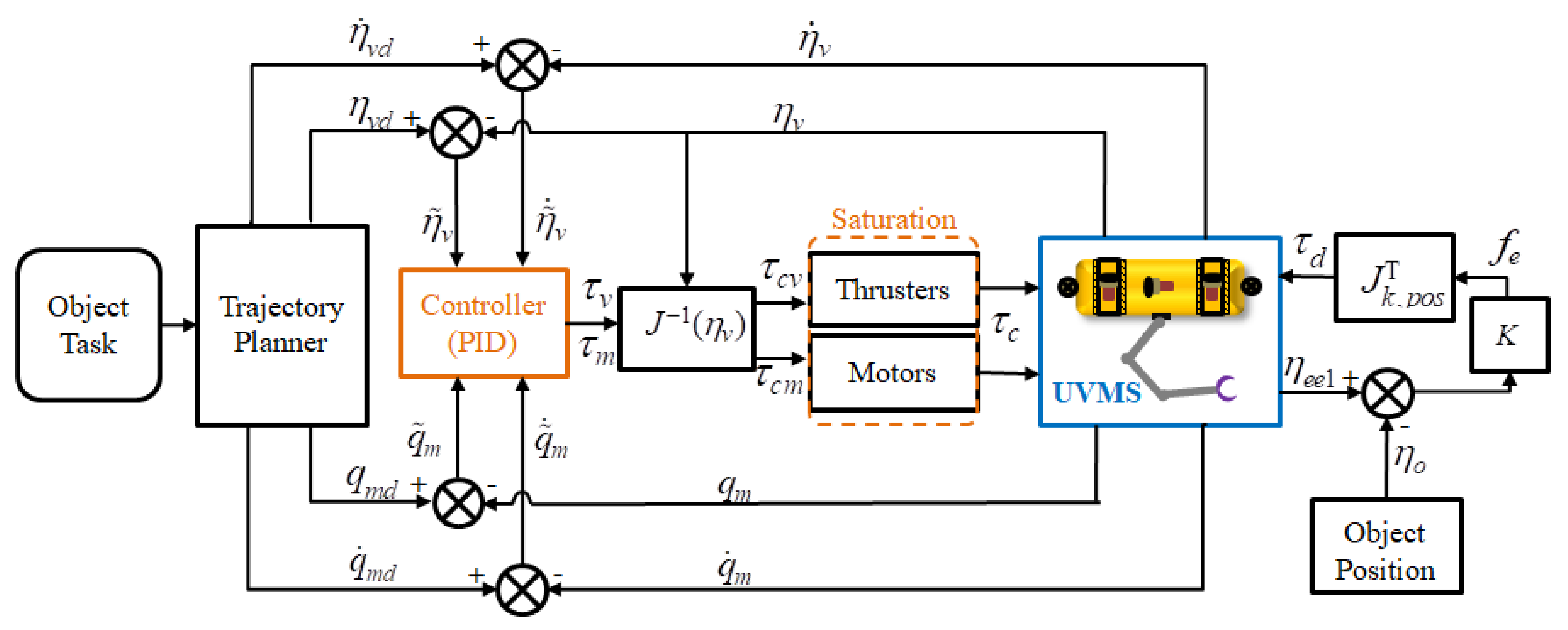
3.1. Proportional-Integral-Derivative (PID) Control
3.2. Model Parameters
3.3. Controller Parameters
4. Simulation and Discussion
4.1. Simulations
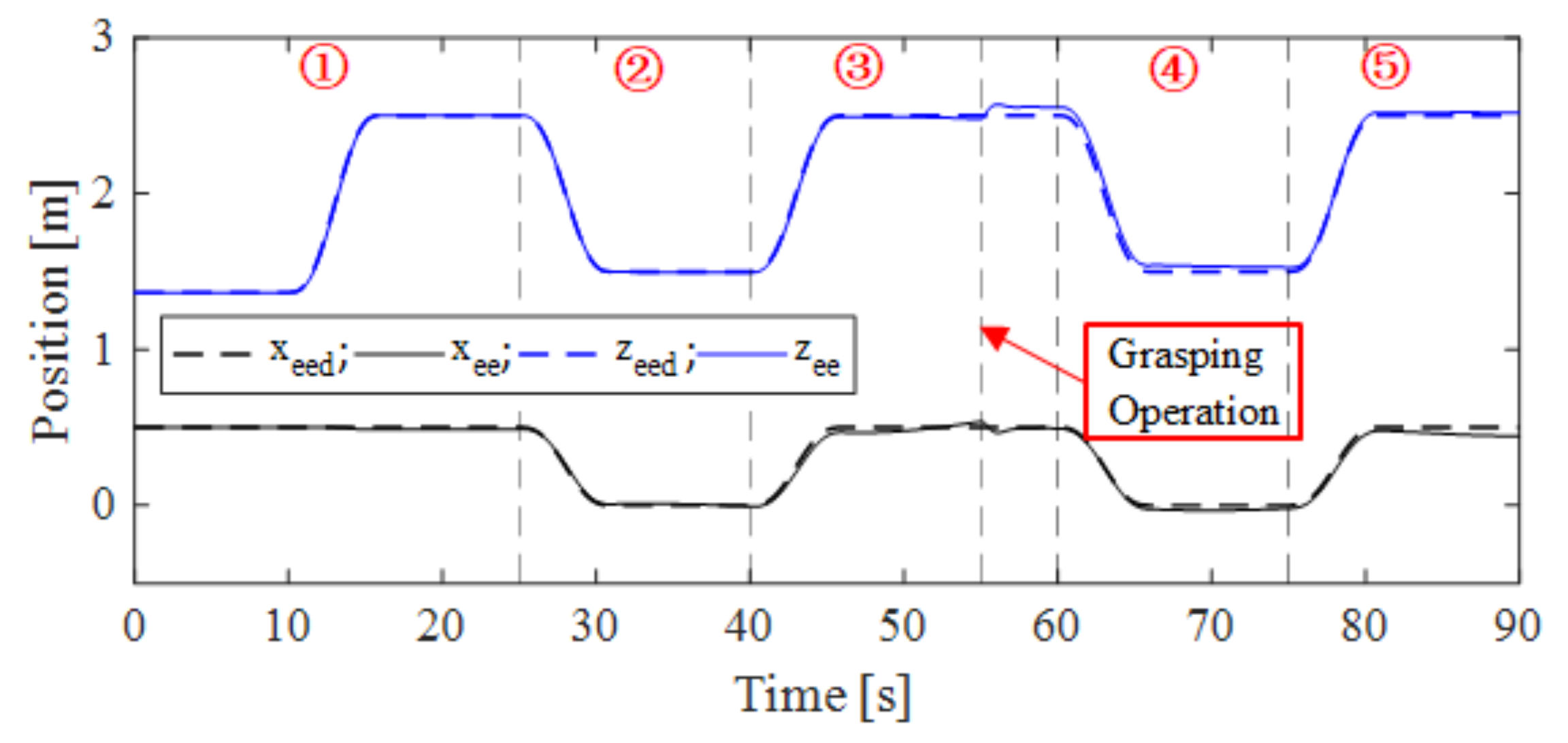
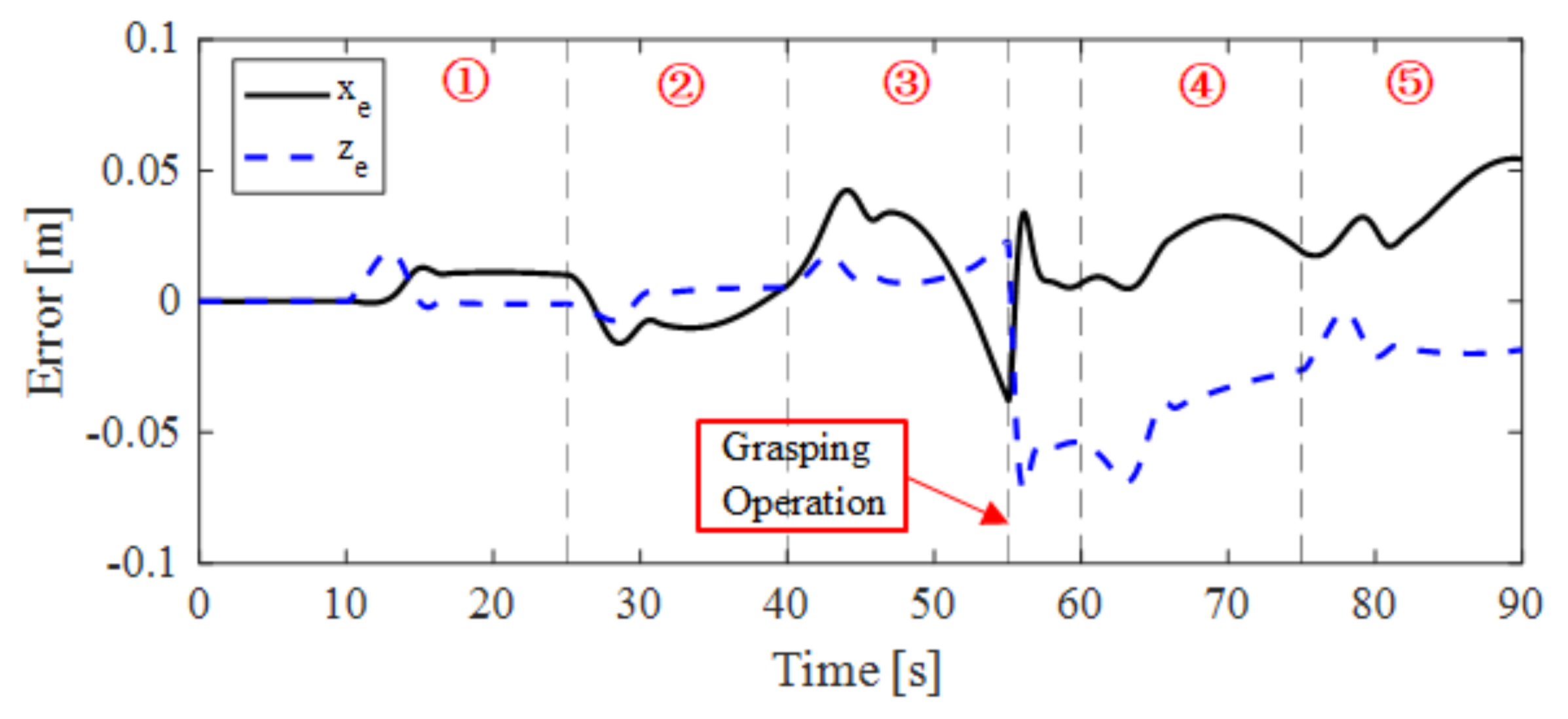
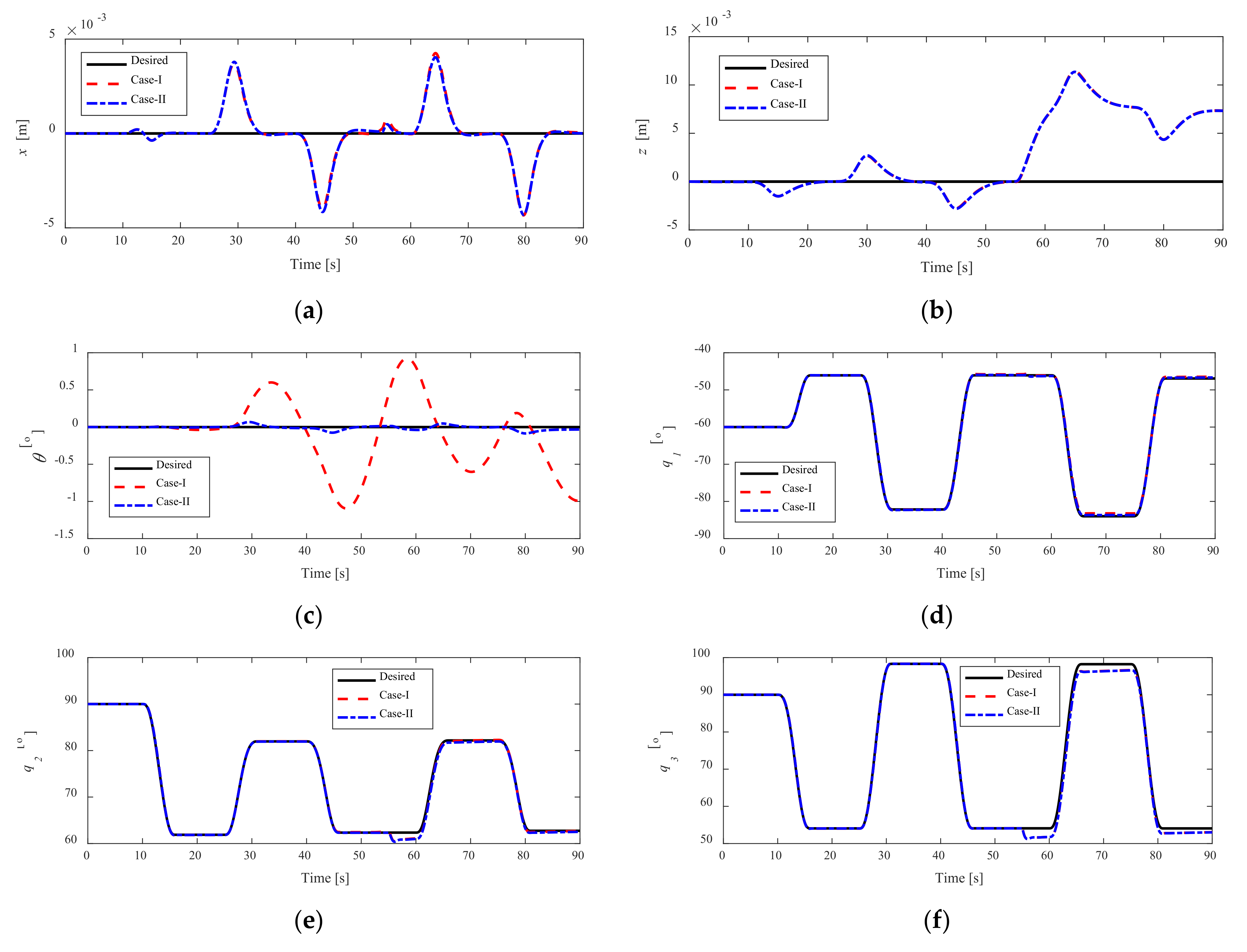
4.1.1. Case-I: Without Attitude Control for Vehicle
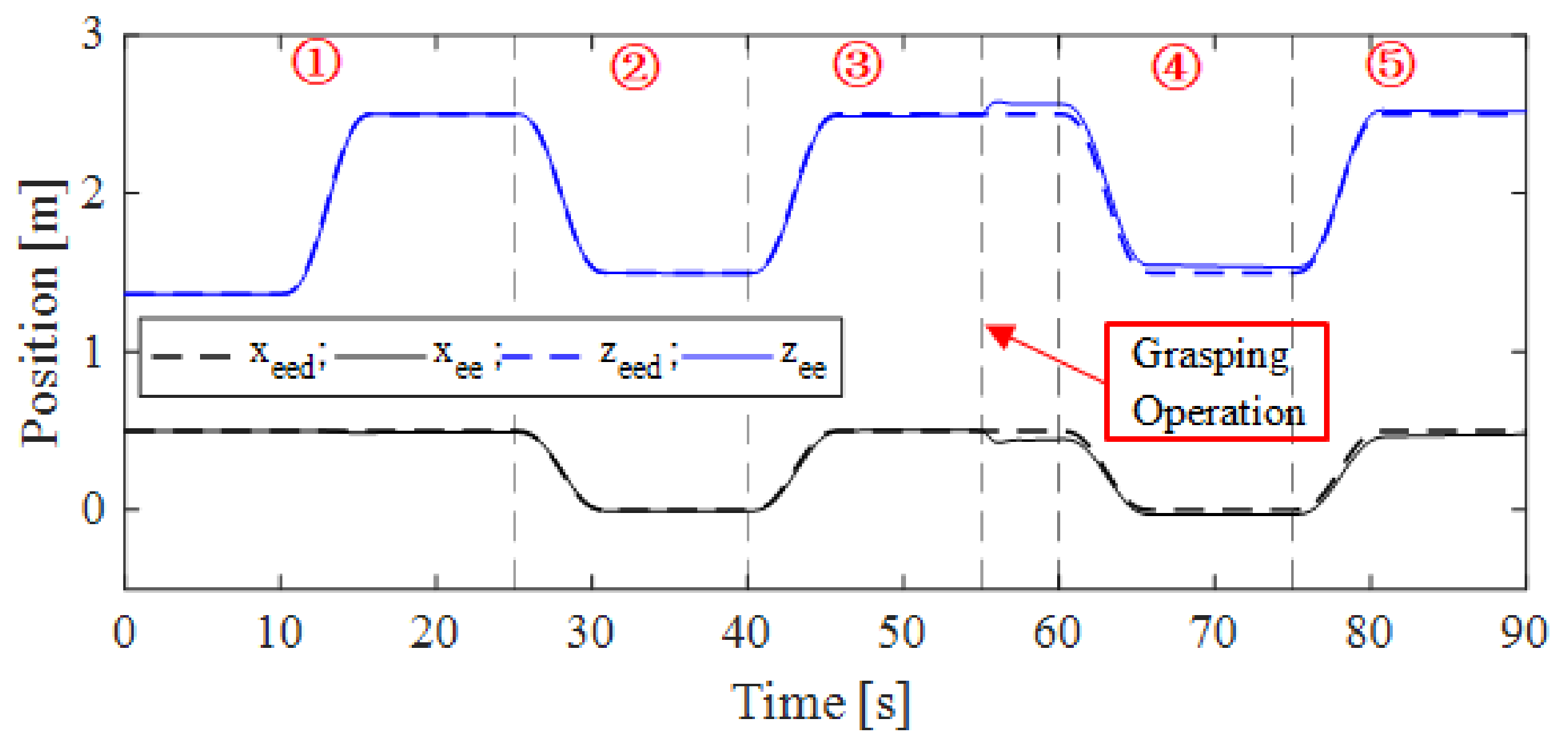
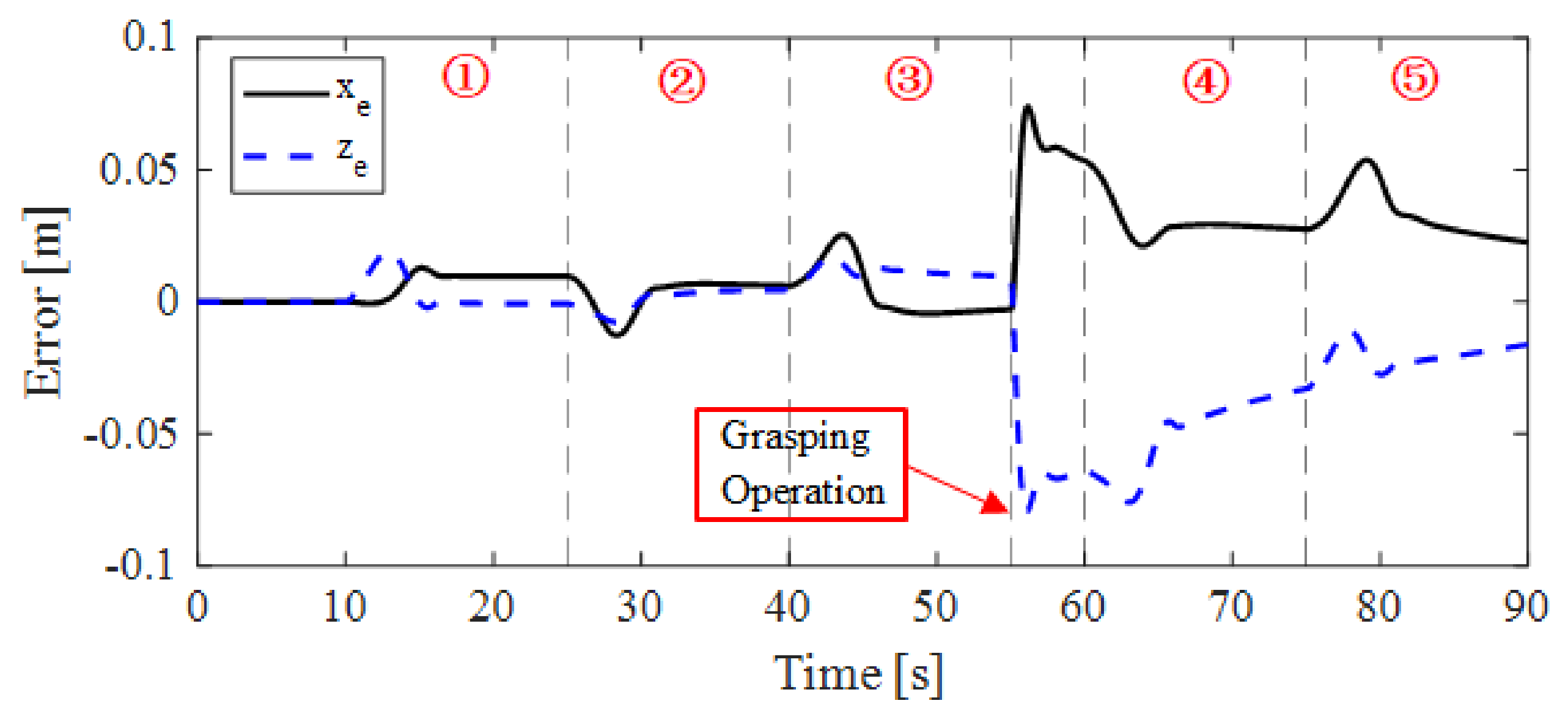
4.1.2. Case-II: With Attitude Control for Vehicle
4.2. Results and Discussions
5. Conclusions
- (1)
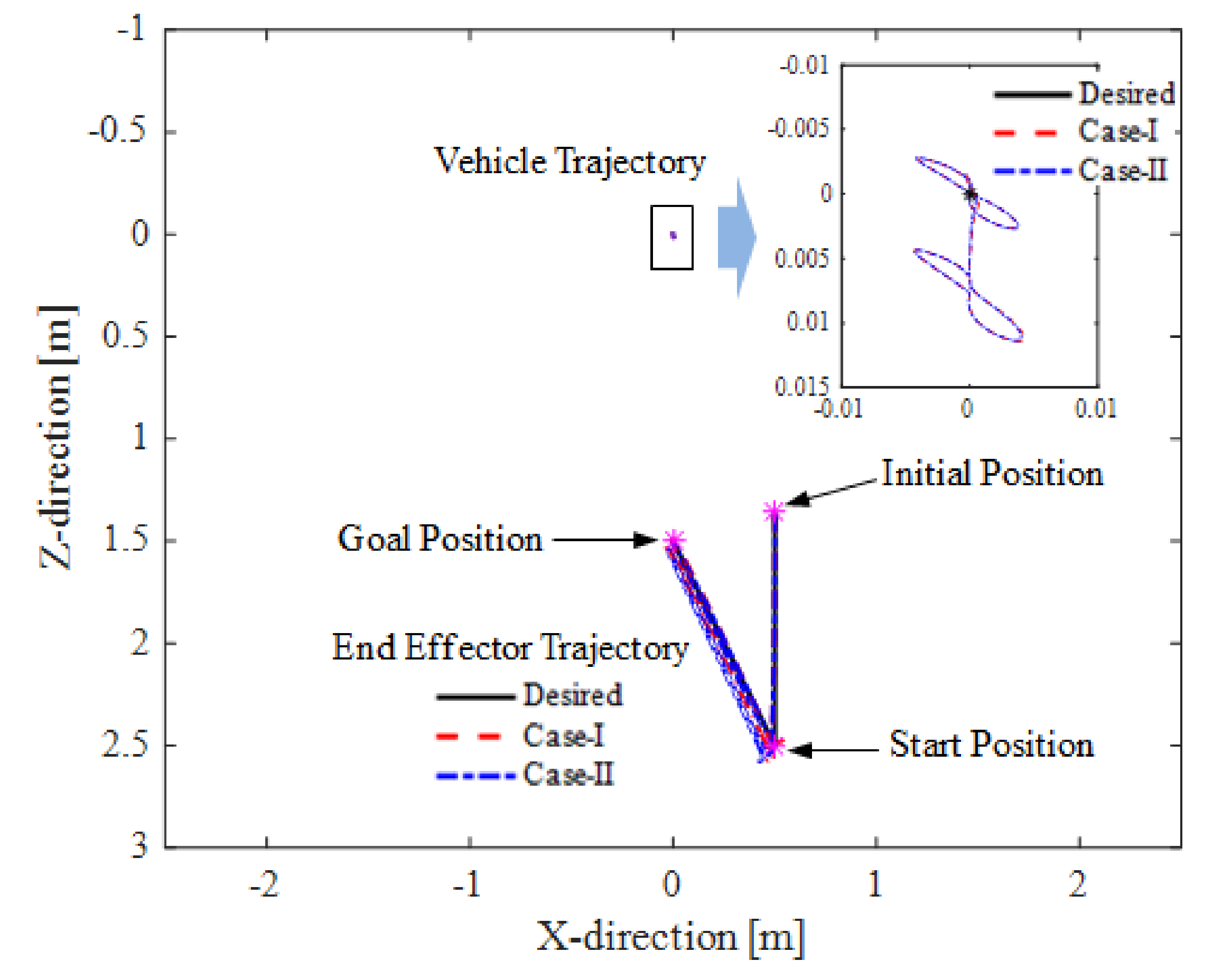
- The position and attitude of the vehicle cannot remain stationary due to the coupling effect between the manipulator and the vehicle. It deteriorates the positioning accuracy of the end effector of the manipulator and is harmful to underwater precision operations or other task.
- (2)
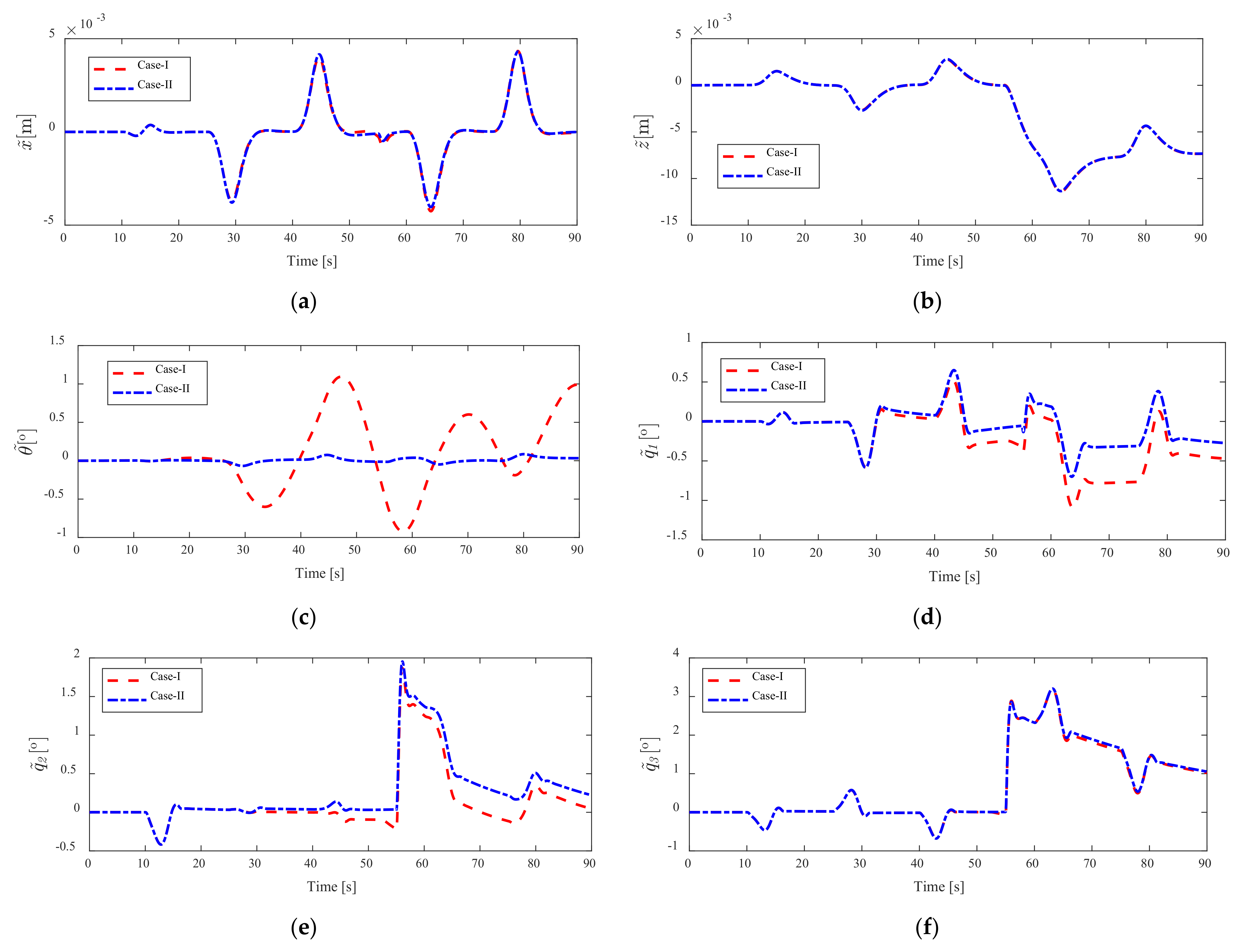
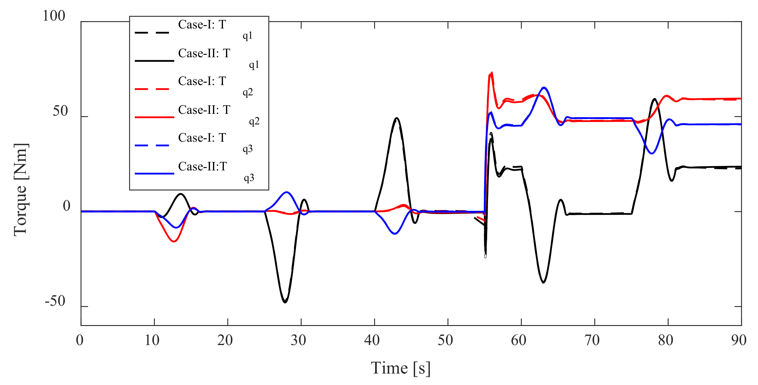
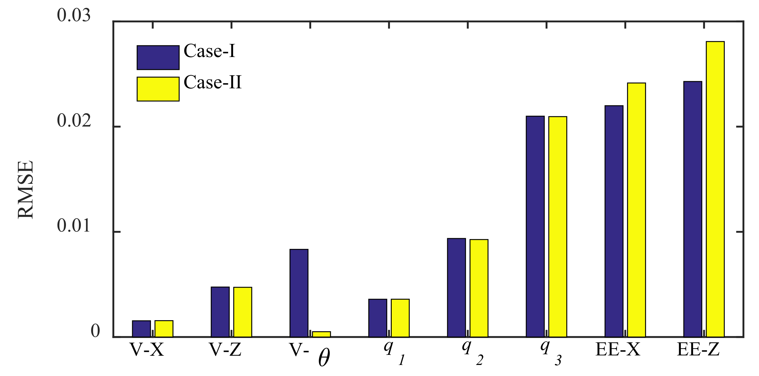
- Trajectory tracking errors and forces/moments acting on the UVMS under fully controlled are performed in comparison with vehicle position control. Vehicle fully controlled can reduce attitude trajectory tracking error effectively.
- (3)
- The hydrostatic restoring force/moment is helpful for the stability of the UVMS system. However, the combined effect between hydrostatic restoring force/moment and system control force will affect the precise positioning of the end effector.
Author Contributions
Funding
Institutional Review Board Statement
Informed Consent Statement
Data Availability Statement
Acknowledgments
Conflicts of Interest
References
- Lin, M.; Yang, C. Ocean observation technologies: A review. Chin. J. Mech. Eng. 2020, 33, 33–50. [Google Scholar] [CrossRef] [Green Version]
- Xu, H.; Jiang, C. Heterogeneous oceanographic exploration system based on USV and AUV: A survey of developments and challenges. J. Univ. Chin. Acad. Sci. 2021, 38, 145–159. [Google Scholar] [CrossRef]
- Van, M.; Bui, D.H.P.; Do, Q.T.; Huynh, T.T.; Lee, S.D.; Choi, H.S. Study on dynamic behavior of unmanned surface vehicle-linked unmanned underwater vehicle system for underwater exploration. Sensors 2020, 20, 1329. [Google Scholar] [CrossRef] [Green Version]
- Cai, M.; Wang, Y.; Wang, S.; Wang, R.; Ren, Y.; Tan, M. Grasping marine products with hybrid-driven underwater vehicle-manipulator system. IEEE Trans. Autom. Sci. Eng. 2020, 17, 1443–1454. [Google Scholar] [CrossRef]
- Vu, M.T.; Thanh, H.L.N.N.; Huynh, T.T.; Thang, Q.; Duc, T.; Hoang, Q.D.; Le, T.H. Station-keeping control of a hovering over-actuated autonomous underwater vehicle under ocean current effects and model uncertainties in horizontal plane. IEEE Access 2021, 9, 6855–6867. [Google Scholar] [CrossRef]
- Simetti, E.; Campos, R.; Vito, D.D.; Quintana, J.; Antonelli, G.; Garcia, R.; Turetta, A. Sea mining exploration with an UVMS: Experimental validation of the control and perception framework. IEEE ASME Trans. Mechatron. 2021, 26, 1635–1645. [Google Scholar] [CrossRef]
- Dunnigan, M.W.; Russell, G.T. Evaluation and reduction of the dynamic coupling between a manipulator and an underwater vehicle. IEEE J. Ocean. Eng. 1998, 23, 260–273. [Google Scholar] [CrossRef]
- McLain, T.W.; Rock, S.M.; Lee, M.J. Experiments in the coordinated control of an underwater arm/vehicle system. Auton. Robot. 1996, 3, 213–232. [Google Scholar] [CrossRef]
- Huang, H.; Zhang, G.C.; Li, J.Y.; Zhang, Q.; Xu, J.Y.; Qin, H.D. Model based adaptive control and disturbance compensation for underwater vehicles. Chin. J. Mech. Eng. 2018, 31, 114–126. [Google Scholar] [CrossRef] [Green Version]
- Pi, R.; Cieślak, P.; Ridao, P.; Sanz, P.J. TWINBOT: Autonomous underwater cooperative transportation. IEEE Access 2021, 9, 37668–37684. [Google Scholar] [CrossRef]
- Evans, J.; Redmond, P.; Plakas, C.; Hamilton, K.; Lane, D. Autonomous docking for intervention-AUVs using sonar and video-based real-time 3D pose estimation. In Proceedings of the MTS/IEEE Oceans 2003, San Diego, CA, USA, 22–26 September 2003; pp. 2201–2210. [Google Scholar] [CrossRef]
- Lane, D.M.; Davies, J.B.C.; Robinson, G.; O’Brien, D.J.; Sneddon, J.; Seaton, E.; Elfstrom, A. The AMADEUS dextrous subsea hand: Design, modeling, and sensor processing. IEEE J. Ocean. Eng. 1999, 24, 96–111. [Google Scholar] [CrossRef]
- Marani, G.; Choi, S.K.; Yuh, J. Underwater autonomous manipulation for intervention missions AUVs. Ocean Eng. 2009, 36, 15–23. [Google Scholar] [CrossRef]
- Ribas, D.; Ridao, P.; Turetta, A.; Melchiorri, C.; Palli, G.; Fernández, J.J.; Sanz, P.J. I-AUV mechatronics integration for the TRIDENT FP7 project. IEEE ASME Trans. Mechatron. 2015, 20, 2583–2592. [Google Scholar] [CrossRef]
- Sivčev, S.; Coleman, J.; Omerdić, E.; Dooly, G.; Toal, D. Underwater manipulators: A review. Ocean Eng. 2018, 163, 431–450. [Google Scholar] [CrossRef]
- Huang, H.; Zhou, Z.; Li, J.; Tang, Q.; Zhang, W.; Gang, W. Investigation on the mechanical design and manipulation hydrodynamics for a small sized, single body and streamlined I-AUV. Ocean Eng. 2019, 186, 106106. [Google Scholar] [CrossRef]
- Tang, C.; Wang, Y.; Wang, S.; Wang, R.; Tan, M. Floating autonomous manipulation of the underwater biomimetic vehicle-manipulator system: Methodology and verification. IEEE Trans. Ind. Electron. 2018, 65, 4861–4870. [Google Scholar] [CrossRef]
- Farivarnejad, H.; Moosavian, S.A.A. Multiple impedance control for object manipulation by a dual arm underwater vehicle–manipulator system. Ocean Eng. 2014, 89, 82–98. [Google Scholar] [CrossRef]
- Birk, A.; Doernbach, T.; Müller, C.A.; Łuczynski, T.; Chavez, A.G.; Koehntopp, D.; Kupcsik, A.; Calinon, S.; Tanwani, A.K.; Antonelli, G.; et al. Dexterous underwater manipulation from onshore locations: Streamlining efficiencies for remotely operated underwater vehicles. IEEE Robot. Autom. Mag. 2018, 25, 24–33. [Google Scholar] [CrossRef]
- Khatib, O.; Yeh, X.; Brantner, G.; Soe, B.; Kim, B.; Ganguly, S.; Stuart, H.; Wang, S.; Cutkosky, M.; Edsinger, A.; et al. Ocean one: A robotic avatar for oceanic discovery. IEEE Robot. Autom. Mag. 2016, 23, 20–29. [Google Scholar] [CrossRef]
- Manley, J.E.; Halpin, S.; Radford, N.; Ondler, M. Aquanaut: A new tool for subsea inspection and intervention. In Proceedings of the OCEANS 2018 MTS/IEEE Charleston, Charleston, SC, USA, 22–25 October 2018; pp. 1–4. [Google Scholar] [CrossRef]
- Marani, G.; Yuh, J. Introduction to Autonomous Manipulation: Case Study with an Underwater Robot, SAUVIM; Springer: New York, NY, USA, 2014. [Google Scholar]
- Ribas, D.; Palomeras, N.; Ridao, P.; Carreras, M.; Mallios, A. Girona 500 AUV: From survey to intervention. IEEE ASME Trans. Mechatron. 2012, 17, 46–53. [Google Scholar] [CrossRef]
- Sarkar, N.; Podder, T.K. Coordinated motion planning and control of autonomous underwater vehicle-manipulator systems subject to drag optimization. IEEE J. Ocean. Eng. 2001, 26, 228–239. [Google Scholar] [CrossRef]
- Antonelli, G.; Chiaverini, S. Fuzzy redundancy resolution and motion coordination for underwater vehicle-manipulator systems. IEEE Trans. Fuzzy Syst. 2003, 11, 109–120. [Google Scholar] [CrossRef]
- Han, J.; Park, J.; Chung, W.K. Robust coordinated motion control of an underwater vehicle-manipulator system with minimizing restoring moments. Ocean Eng. 2011, 38, 1197–1206. [Google Scholar] [CrossRef]
- Kang, J.I.; Choi, H.S.; Duc, N.N.; Ji, D.H.; Kim, J.Y. Experimental study of dynamic stability of underwater vehicle-manipulator system using zero moment point. J. Mar. Sci. Tech. 2017, 25, 767–774. [Google Scholar] [CrossRef]
- Zhang, M.J.; Peng, S.Q.; Chu, Z.Z.; Wang, Y.J. Motion planning of underwater vehicle-manipulator system with joint limit. Appl. Mech. Mater. 2012, 220–223, 1767–1771. [Google Scholar] [CrossRef]
- Sotiropoulos, P.; Kolonias, V.; Aspragathos, N.; Housos, E. Rapid motion planning algorithm for optimal UVMS interventions in semi-structured environments using gpus. Robot. Auton. Syst. 2015, 74, 15–29. [Google Scholar] [CrossRef]
- Youakim, D.; Ridao, P. Motion planning survey for autonomous mobile manipulators underwater manipulator case study. Robot. Auton. Syst. 2018, 107, 20–44. [Google Scholar] [CrossRef]
- Liu, J.; Du, J. Composite learning tracking control for underactuated autonomous underwater vehicle with unknown dynamics and disturbances in three-dimension space. Appl. Ocean Res. 2021, 112, 102686. [Google Scholar] [CrossRef]
- Korkmaz, O.; Ider, S.K.; Ozgoren, M.K. Trajectory tracking control of an underactuated underwater vehicle redundant manipulator system. Asian J. Control 2016, 18, 1593–1607. [Google Scholar] [CrossRef]
- Mohan, S.; Kim, J. Indirect adaptive control of an autonomous underwater vehicle-manipulator system for underwater manipulation tasks. Ocean Eng. 2012, 54, 233–243. [Google Scholar] [CrossRef]
- Mohan, S.; Kim, J. Coordinated motion control in task space of an autonomous underwater vehicle—manipulator system. Ocean Eng. 2015, 104, 155–167. [Google Scholar] [CrossRef]
- Han, H.; Wei, Y.; Ye, X.; Liu, W. Motion planning and coordinated control of underwater vehicle-manipulator systems with inertial delay control and fuzzy compensator. Appl. Sci. Basel 2020, 10, 3944. [Google Scholar] [CrossRef]
- Barbalata, C.; Dunnigan, M.W.; Petillot, Y. Coupled and decoupled force/motion controllers for an underwater vehicle-manipulator system. J. Mar. Sci. Eng. 2018, 6, 96. [Google Scholar] [CrossRef] [Green Version]
- Huang, H.; Tang, Q.; Li, J.; Zhang, W.; Bao, X.; Zhu, H.; Wang, G. A review on underwater autonomous environmental perception and target grasp, the challenge of robotic organism capture. Ocean Eng. 2020, 195, 106644. [Google Scholar] [CrossRef]
- Conti, R.; Fanelli, F.; Meli, E.; Ridolfi, A.; Costanzi, R. A free floating manipulation strategy for autonomous underwater vehicles. Robot. Auton. Syst. 2017, 87, 133–146. [Google Scholar] [CrossRef]
- Anderlini, E.; Parker, G.G.; Thomas, G. Control of a ROV carrying an object. Ocean Eng. 2018, 165, 307–318. [Google Scholar] [CrossRef]
- Londhe, P.S.; Mohan, S.; Patre, B.M.; Waghmare, L.M. Robust task-space control of an autonomous underwater vehicle-manipulator system by PID-like fuzzy control scheme with disturbance estimator. Ocean Eng. 2017, 139, 1–13. [Google Scholar] [CrossRef]
- Taira, Y.; Sagara, S.; Oya, M. Model-based motion control for underwater vehicle-manipulator systems with one of the three types of servo subsystems. Artif. Life Robot. 2019, 25, 133–148. [Google Scholar] [CrossRef]
- Wang, J.; Hung, J.Y. Adaptive backstepping control for an underwater vehicle manipulator system using fuzzy logic. In Proceedings of the IECON 2018—44th Annual Conference of the IEEE Industrial Electronics Society, Washington, DC, USA, 21–23 October 2018; pp. 5600–5606. [Google Scholar] [CrossRef]
- Yang, C.; Yao, F.; Zhang, M.-J. Adaptive Backstepping Terminal Sliding Mode Control Method Based on Recurrent Neural Networks for Autonomous Underwater Vehicle. Chin. J. Mech. Eng. 2018, 31, 110. [Google Scholar] [CrossRef] [Green Version]
- Von Ellenrieder, K.D. Stable Backstepping Control of Marine Vehicles with Actuator Rate Limits and Saturation. IFAC-PapersOnLine 2018, 51, 262–267. [Google Scholar] [CrossRef]
- Mohan, S. Proportional-Derivative Observer-Based Backstepping Control for an Underwater Manipulator. Math. Probl. Eng. 2011, 2011, 397092. [Google Scholar] [CrossRef]
- Dai, Y.; Yu, S.; Yan, Y.; Yu, X. An EKF-Based Fast Tube MPC Scheme for Moving Target Tracking of a Redundant Underwater Vehicle-Manipulator System. IEEE/ASME Trans. Mechatron. 2019, 24, 2803–2814. [Google Scholar] [CrossRef]
- Gong, P.; Yan, Z.; Zhang, W.; Tang, J. Lyapunov-based model predictive control trajectory tracking for an autonomous underwater vehicle with external disturbances. Ocean Eng. 2021, 232, 109010. [Google Scholar] [CrossRef]
- Yan, Z.; Gong, P.; Zhang, W.; Wu, W. Model predictive control of autonomous underwater vehicles for trajectory tracking with external disturbances. Ocean Eng. 2020, 217, 107884. [Google Scholar] [CrossRef]
- Nikou, A.; Verginis, C.K.; Heshmati-Alamdari, S.; Dimarogonas, D.V. A robust non-linear MPC framework for control of underwater vehicle manipulator systems under high-level tasks. IET Control. Theory Appl. 2021, 15, 323–337. [Google Scholar] [CrossRef]
- Esfahani, H.N. Robust model predictive control for autonomous underwater vehicle-manipulator system with fuzzy com-pensator. Pol. Marit. Res. 2019, 26, 104–114. [Google Scholar] [CrossRef] [Green Version]
- Song, D.; Hou, R.; Li, C.; Hung, J.Y.; Wang, J. Complementary Constrained Model Predictive Depth Control of a Hybridly-Actuated Submarine Drifter. IEEE Access 2020, 8, 151692–151704. [Google Scholar] [CrossRef]
- Cao, Y.; Li, B.; Li, Q.; Stokes, A.A.; Ingram, D.M.; Kiprakis, A. A Nonlinear Model Predictive Controller for Remotely Operated Underwater Vehicles with Disturbance Rejection. IEEE Access 2020, 8, 158622–158634. [Google Scholar] [CrossRef]
- Han, L.; Tang, G.; Cheng, M.; Huang, H.; Xie, D. Adaptive Nonsingular Fast Terminal Sliding Mode Tracking Control for an Underwater Vehicle-Manipulator System with Extended State Observer. J. Mar. Sci. Eng. 2021, 9, 501. [Google Scholar] [CrossRef]
- El-Ferik, S.; Elkhider, S.; Ghommam, J. Adaptive containment control of multi-leader fleet of underwater vehicle-manipulator autonomous systems carrying a load. Int. J. Syst. Sci. 2019, 50, 1501–1516. [Google Scholar] [CrossRef]
- Gao, J.; Liang, X.; Chen, Y.; Zhang, L.; Jia, S. Hierarchical image-based visual serving of underwater vehicle manipulator systems based on model predictive control and active disturbance rejection control. Ocean Eng. 2021, 229, 108814. [Google Scholar] [CrossRef]
- Xie, T.; Li, Y.; Jiang, Y.; An, L.; Wu, H. Backstepping active disturbance rejection control for trajectory tracking of underactuated autonomous underwater vehicles with position error constraint. Int. J. Adv. Robot. Syst. 2020, 17, 397092. [Google Scholar] [CrossRef] [Green Version]
- Heshmati-Alamdari, S.; Bechlioulis, C.P.; Karras, G.C.; Nikou, A.; Dimarogonas, D.V.; Kyriakopoulos, K.J. A robust interaction control approach for underwater vehicle manipulator systems. Annu. Rev. Control. 2018, 46, 315–325. [Google Scholar] [CrossRef]
- Bai, X.; Wang, Y.; Wang, R.; Wang, S.; Tan, M. Dynamic surface control for an underactuated underwater biomimetic vehicle-manipulator system. In Proceedings of the 2021 IEEE International Conference on Real-time Computing and Robotics (RCAR), Xining, China, 15–19 July 2021; pp. 205–210. [Google Scholar] [CrossRef]
- Von Ellenrieder, K.D. Dynamic surface control of trajectory tracking marine vehicles with actuator magnitude and rate limits. Automatica 2019, 105, 433–442. [Google Scholar] [CrossRef]
- Dai, P.; Lu, W.; Le, K.; Liu, D. Sliding Mode Impedance Control for contact intervention of an I-AUV: Simulation and experimental validation. Ocean Eng. 2020, 196, 106855. [Google Scholar] [CrossRef]
- Rojsiraphisal, T.; Mobayen, S.; Asad, J.H.; Vu, M.T.; Chang, A.; Puangmalai, J. Fast Terminal Sliding Control of Underactuated Robotic Systems Based on Disturbance Observer with Experimental Validation. Mathematics 2021, 9, 1935. [Google Scholar] [CrossRef]
- Zhou, Z.; Tang, G.; Huang, H.; Han, L.; Xu, R. Adaptive nonsingular fast terminal sliding mode control for underwater manipulator robotics with asymmetric saturation actuators. Control. Theory Technol. 2020, 18, 81–91. [Google Scholar] [CrossRef]
- Liu, X.; Zhang, M.; Chen, J.; Yin, B. Trajectory tracking with quaternion-based attitude representation for autonomous underwater vehicle based on terminal sliding mode control. Appl. Ocean Res. 2020, 104, 102342. [Google Scholar] [CrossRef]
- Wang, Y.; Li, B.; Yan, F.; Chen, B. Practical adaptive fractional-order nonsingular terminal sliding mode control for a cable-driven manipulator. Int. J. Robust Nonlinear Control. 2019, 29, 1396–1417. [Google Scholar] [CrossRef]
- Vu, M.T.; Le, T.-H.; Thanh, H.L.N.N.; Huynh, T.-T.; Van, M.; Hoang, Q.-D.; Do, T.D. Robust Position Control of an Over-actuated Underwater Vehicle under Model Uncertainties and Ocean Current Effects Using Dynamic Sliding Mode Surface and Optimal Allocation Control. Sensors 2021, 21, 747. [Google Scholar] [CrossRef]
- Thanh, H.L.N.N.; Vu, M.T.; Mung, N.X.; Nguyen, N.P.; Phuong, N.T. Perturbation Observer-Based Robust Control Using a Multiple Sliding Surfaces for Nonlinear Systems with Influences of Matched and Unmatched Uncertainties. Math. 2020, 8, 1371. [Google Scholar] [CrossRef]
- Muñoz, F.; Cervantes-Rojas, J.; Valdovinos, J.; Sandre-Hernández, O.; Salazar, S.; Romero, H. Dynamic Neural Network-Based Adaptive Tracking Control for an Autonomous Underwater Vehicle Subject to Modeling and Parametric Uncertainties. Appl. Sci. 2021, 11, 2797. [Google Scholar] [CrossRef]
- Mu, W.; Wang, Y.; Sun, H.; Liu, G. Double-Loop Sliding Mode Controller with An Ocean Current Observer for the Trajectory Tracking of ROV. J. Mar. Sci. Eng. 2021, 9, 1000. [Google Scholar] [CrossRef]
- Wei, Y.; Zheng, Z.; Li, Q.; Jiang, Z.; Yang, P. Robust tracking control of an underwater vehicle and manipulator system based on double closed-loop integral sliding mode. Int. J. Adv. Robot. Syst. 2020, 17, 172988142094177. [Google Scholar] [CrossRef]
- Qiao, L.; Zhang, W. Double-loop integral terminal sliding mode tracking control for UUVs with adaptive dynamic compen-sation of uncertainties and disturbances. IEEE J. Ocean. Eng. 2018, 44, 1–25. [Google Scholar]
- Yang, C.; Yao, F.; Zhang, M.; Zhang, Z.; Wu, Z.; Dan, P. Adaptive Sliding Mode PID Control for Underwater Manipulator Based on Legendre Polynomial Function Approximation and Its Experimental Evaluation. Appl. Sci. 2020, 10, 1728. [Google Scholar] [CrossRef] [Green Version]
- Wang, H.; Li, X.; Liu, X.; Karkoub, M.; Zhou, L. Fuzzy Sliding Mode Active Disturbance Rejection Control of an Autonomous Underwater Vehicle-Manipulator System. J. Ocean Univ. China 2020, 19, 1081–1093. [Google Scholar] [CrossRef]
- Yuguang, Z.; Fan, Y. Dynamic modeling and adaptive fuzzy sliding mode control for multi-link underwater manipulators. Ocean Eng. 2019, 187, 106202. [Google Scholar] [CrossRef]
- Patre, B.; Londhe, P.; Waghmare, L.; Mohan, S. Disturbance estimator based non-singular fast fuzzy terminal sliding mode control of an autonomous underwater vehicle. Ocean Eng. 2018, 159, 372–387. [Google Scholar] [CrossRef]
- Londhe, P.; Patre, B.M. Adaptive fuzzy sliding mode control for robust trajectory tracking control of an autonomous underwater vehicle. Intell. Serv. Robot. 2018, 12, 87–102. [Google Scholar] [CrossRef]
- Casalino, G.; Caccia, M.; Caselli, S.; Melchiorri, C.; Antonelli, G.; Caiti, A.; Indiveri, G.; Cannata, G.; Simetti, E.; Torelli, S.; et al. Underwater Intervention Robotics: An Outline of the Italian National Project MARIS. Mar. Technol. Soc. J. 2016, 50, 98–107. [Google Scholar] [CrossRef]
- Li, J.; Huang, H.; Xu, Y.; Wu, H.; Wan, L. Uncalibrated Visual Servoing for Underwater Vehicle Manipulator Systems with an Eye in Hand Configuration Camera. Sensors 2019, 19, 5469. [Google Scholar] [CrossRef] [PubMed] [Green Version]
- Heshmati-Alamdari, S.; Eqtami, A.; Karras, G.C.; Dimarogonas, D.V.; Kyriakopoulos, K.J. A Self-triggered Position Based Visual Servoing Model Predictive Control Scheme for Underwater Robotic Vehicles. Machines 2020, 8, 33. [Google Scholar] [CrossRef]
- Fossen, T.I. Handbook of Marine Craft Hydrodynamics and Motion Control; John Wiley & Sons: Chichester, UK, 2011. [Google Scholar]
- Antonelli, G. Underwater Robots, 4th ed; Springer International Publishing AG: Cham, Switzerland, 2018. [Google Scholar]
- Healey, A.; Lienard, D. Multivariable sliding mode control for autonomous diving and steering of unmanned underwater vehicles. IEEE J. Ocean. Eng. 1993, 18, 327–339. [Google Scholar] [CrossRef] [Green Version]


| Parameters | Values | Parameters | Values | ||
|---|---|---|---|---|---|
| Length [m] | 5.3 | Mass [kg] | 5454.54 | ||
| Buoyancy [N] | 53,400 | Gravity [N] | 53,400 | ||
| Center of buoyancy [m] | [0,0,0] | Center of mass [m] | [0,0,0.061] | ||
| Maximum translational velocity [m/s] | [0.2,0.2,0.2] | Maximum rotational velocity [rad/s] | [0.2,0.2,0.2] | ||
| Maximum control force [N] | [200,200,400] | Maximum control moment [Nm] | [200,200,200] | ||
| Moment of inertia [kg•m2] | Ixx | 2038 | Moment of inertia [kg•m2] | Ixy | −13.58 |
| Iyy | 13,587 | Iyz | −13.58 | ||
| Izz | 13,587 | Ixz | −13.58 | ||
| Parameters | Link 1 | Link 2 | Link 3 | |
|---|---|---|---|---|
| Mass [kg] | 31.4 | 20.1 | 15.4 | |
| qm [rad] | q1 | q2 | q3 | |
| Radius [m] | 0.1 | 0.08 | 0.07 | |
| Length [m] | 1 | 1 | 1 | |
| Joint angular velocity [deg/s] | 20 | 20 | 20 | |
| Maximum joint torque [Nm] | 300 | 200 | 150 | |
| Viscous friction [Nms] | 30 | 20 | 5 | |
| Moment of inertia [kg•m2] | Ixx | 1.65 | 0.75 | 0.4 |
| Iyy | 11 | 6.3 | 4 | |
| Izz | 11 | 6.3 | 4 | |
| Parameters | Values | Parameters | Values | ||
|---|---|---|---|---|---|
| Sphere radius [m] | 0.1 | Mass [kg] | 9.21 | ||
| Buoyancy [N] | 50.96 | Gravity [N] | 90.26 | ||
| Moment of inertia [kg•m2] | Ixx | 0.037 | Moment of inertia [kg•m2] | Ixy | 0 |
| Iyy | 0.037 | Iyz | 0 | ||
| Izz | 0.037 | Ixz | 0 | ||
| Number | Time [s] | Action of Manipulator |
|---|---|---|
| ① | 0~25 | From initial position to start position |
| ② | 25~40 | From start position to goal position |
| ③ | 40~55 | From goal position to start position |
| - | 55~60 | Grasping operation |
| ④ | 60~75 | From start position to goal position |
| ⑤ | 75~90 | From goal position to start position |
Publisher’s Note: MDPI stays neutral with regard to jurisdictional claims in published maps and institutional affiliations. |
© 2021 by the authors. Licensee MDPI, Basel, Switzerland. This article is an open access article distributed under the terms and conditions of the Creative Commons Attribution (CC BY) license (https://creativecommons.org/licenses/by/4.0/).
Share and Cite
Chang, Z.; Zhang, Y.; Zheng, Z.; Zhao, L.; Shen, K. Dynamics Simulation of Grasping Process of Underwater Vehicle-Manipulator System. J. Mar. Sci. Eng. 2021, 9, 1131. https://doi.org/10.3390/jmse9101131
Chang Z, Zhang Y, Zheng Z, Zhao L, Shen K. Dynamics Simulation of Grasping Process of Underwater Vehicle-Manipulator System. Journal of Marine Science and Engineering. 2021; 9(10):1131. https://doi.org/10.3390/jmse9101131
Chicago/Turabian StyleChang, Zongyu, Yang Zhang, Zhongqiang Zheng, Lin Zhao, and Kunfan Shen. 2021. "Dynamics Simulation of Grasping Process of Underwater Vehicle-Manipulator System" Journal of Marine Science and Engineering 9, no. 10: 1131. https://doi.org/10.3390/jmse9101131
APA StyleChang, Z., Zhang, Y., Zheng, Z., Zhao, L., & Shen, K. (2021). Dynamics Simulation of Grasping Process of Underwater Vehicle-Manipulator System. Journal of Marine Science and Engineering, 9(10), 1131. https://doi.org/10.3390/jmse9101131