Article

An Object Model for Seafloor Observatory Sensor Control in the East China Sea

1
State Key Laboratory of Marine Geology, Tongji University, Shanghai 200092, China
2
Institute of Deep-Sea Science and Engineering, Chinese Academy of Sciences, Sanya 572000, China
*
Author to whom correspondence should be addressed.
J. Mar. Sci. Eng. 2020, 8(9), 716; https://doi.org/10.3390/jmse8090716
Submission received: 31 July 2020 / Revised: 3 September 2020 / Accepted: 11 September 2020 / Published: 16 September 2020

Abstract

:
Seafloor observatories enable long-term, real-time, and continuous observation that marks a new way for oceanographic measurements. In terms of seafloor observatory research, sensor control is a key issue for the stable and effective operations of functional observatories. In this paper, an object model is proposed to standardize seafloor observatory sensor control and data acquisition. The object model is conceptionally designed as a set of sensor resource objects, based on the attributes and operations of which a client–server sensor control architecture is enabled for bidirectional information flow of control commands and observation data. The object model-based architecture is implemented with a prototype control system for plug-and-play enablement. The prototype system was put into a series of tests before applied to the East China Sea Experimental Seafloor Observatory, performing consistently with all the project requirements. Given the successful experiment, the object model design and prototype implementation are feasible to resolve seafloor observatory sensor control and beneficial for ocean observatory sciences.

1. Introduction

Seafloor observatories emerge as a response to the development of earth system science [1]. Global change research over the past 30 years has strongly suggested that oceans play key parts in global climate change, and that long-term and continuous observation with scientific instruments under the sea is a necessity to record changes in multi-spatial-temporal scales [2]. This is facilitated with seafloor observatories that are designed to provide diverse in situ sensor equipment with continuous power supply and data communication [3]. Multidisciplinary measurements within the water body are thus acquired in a continuous way, contributing to a better understanding of the ocean interior [4]. The construction of seafloor observatories marks a new way of oceanographic measurements and research, one recent update of which is for the monitoring of ecosystem indicators [5,6,7].
Many projects or programs on seafloor observatory systems are in the implementation or planning phase at different locations. The United States first researched seafloor observatories and have deployed observatories such as LEO-15, HUGO, MARS, and OOI [8,9,10,11]. OOI is a networked infrastructure with science-driven sensor systems to measure multidisciplinary variables at coastal, regional, and global scales. Regarding the European Multidisciplinary Seafloor and water-column Observatory (EMSO), GEOSTAR, SN-1, and OBSEA are the representatives of the distributed observatory infrastructure in recent years [12,13,14]. In addition, ARIM is a good example of the flexible robotic deep-sea observatory networks being developed at the Lofoten-Vesterålen (LoVe) infrastructure [15,16]. Japan mainly concentrates on earthquake early warning when deploying seafloor observatories like GeO-TOC and DONET [17,18]. Canada has successfully established VENUS and NEPTUNE Canada that are integrated into ONC (Ocean Networks Canada), which is leading seafloor observatory research as the first multi-node cabled seafloor observatories worldwide [19]. China has also been designing and building seafloor observatories in both the East China Sea and the South China Sea, the first trial of which is the Xiaoqushan Seafloor Observatory [20]. China National Scientific Seafloor Observatory is now in preparation and Tongji University is taking the lead.
In terms of seafloor observatory research, sensor control is a key issue for effective and stable observatory operations. The sensor control system guarantees that all the raw data acquired by observatory sensors meet with dynamic observation demands, which lays a foundation for subsequent data processing and storage, data analysis, and closed-loop data applications [21]. Some researches on seafloor observatory sensor control have been conducted in recent years. Based on Enterprise Service Bus, Barnes et al. designed a data acquisition framework for the ONC observatory interaction of instrument monitoring and control, as well as data acquisition and storage [22]. Joaquin et al. designed a sensor interfacing approach for EMSO observatory instruments, using the Sensor Web Enablement infrastructure to manage the data acquisition from undersea sensors [23]. Aguzzi et al. present a hierarchic marine information treatment from sensor control and data acquisition to automated data processing and ecological indicator computing [24]. Leadbetter et al. designed a streaming data system for the sensor control and data acquisition of Galway Bay cable observatory, enabled by microservices with exposed HTTP interfaces [25]. Rodero et al. employed the uFrame software framework to design the OOI cyberinfrastructure, which integrates instruments, platform drivers, datasets, and algorithms to produce data products on demand [26]. Arnaud et al. designed state-full web services with workflow bindings for dynamic user control of observatory configuration as well as observatory instrument and data processes [27]. Liu et al. developed an underwater control system of OUC-Raman instrument node for long-term observation of chemical environment under the sea [28]. Gao et al. designed a data acquisition and management system for seafloor observatories, which transmits IP packets through optical networks combined with event-triggered and timing-driven devices [29]. Yu et al. researched the remote communication architecture, plug-and-play approach, and prototype control system for cabled seafloor observatories established in the East China Sea [30,31].
In this paper, an object model is researched to standardize seafloor observatory sensor control, of which object-oriented approaches in modelling sensor resources for seafloor observatory control cannot be found in literature. The paper organization is outlined as follows. In Section 2, the object model is introduced in terms of sensor information description, sensor resource object, and attributes and operations of the in-situ sensor resource object. In Section 3, the feasibility of the object model is fully demonstrated with the seafloor observatory sensor control experiment, from the model-based control architecture design to the prototype system implementation and application. In Section 4, the proposed object model is discussed for its contributions. Section 5 concludes the paper.

2. Object Model Design

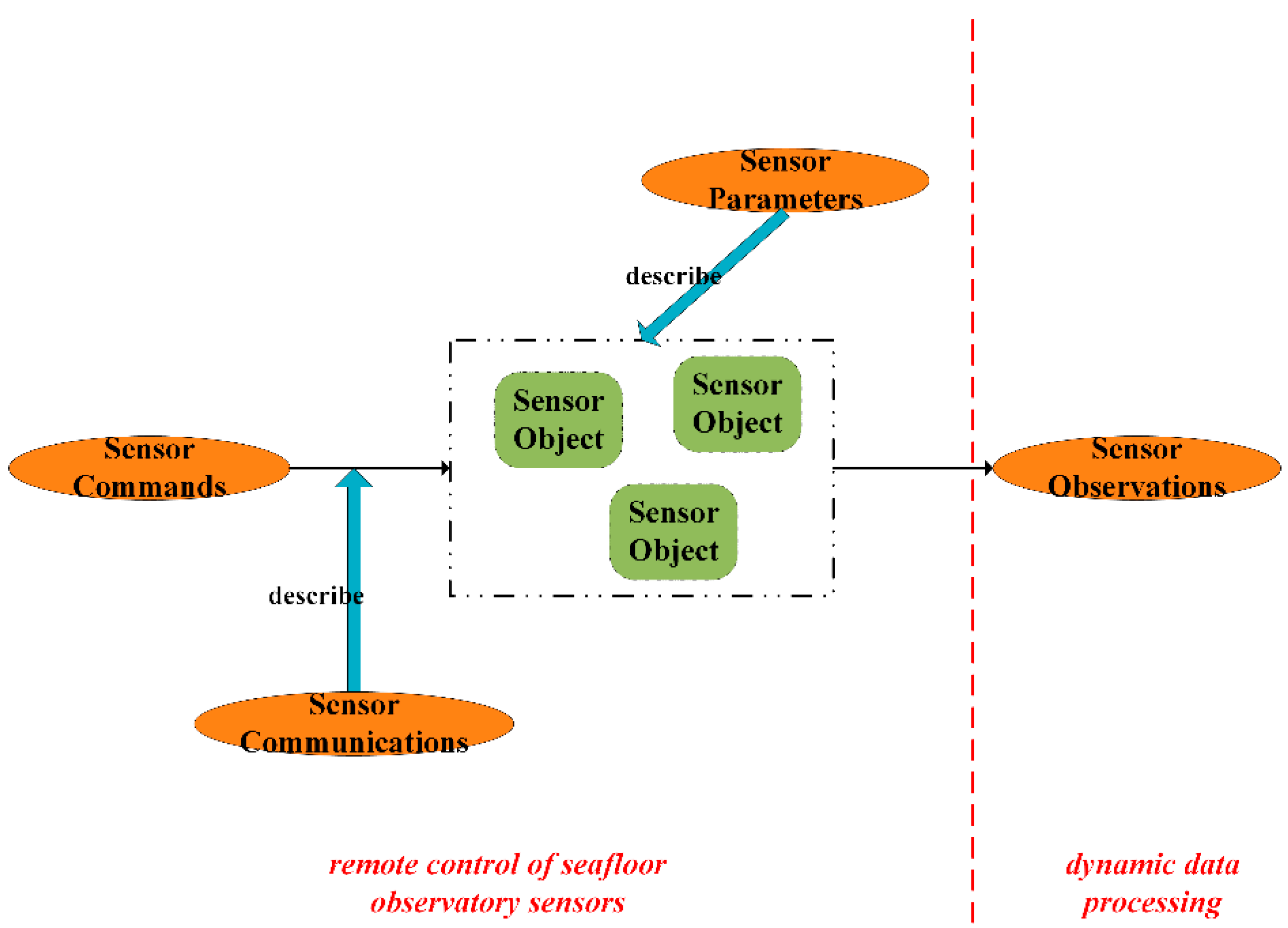
2.1. Sensor Information Description

The sensor information contributing to seafloor observatory sensor control logic can be classified into four categories: sensor communications, sensor commands, sensor parameters, and sensor observations [23]. Sensor communications focus on the data transmission between the control center on shore and undersea sensor equipment, covering the information such as scientific observation node and IP/port pair. Sensor commands are used to control various observatory sensors to execute dynamic observation plans, which contain the information of command names, command descriptions, command thresholds, and default command configurations. Sensor parameters specify the observation capabilities of in situ sensors and mainly consist of sensor types, application ranges, measurement specifications, and observation parameters. Sensor observations describe the observation data from observatory sensors executing control commands, of which the link information to the sensor manual details the data format and data processing for the obtained observations.
As shown in Figure 1, the combination of all these categories of sensor information fully demonstrates the sensor control logic for seafloor observatories. Based on the descriptions of sensor communications, the remote communications with observatory sensors are established while sensor commands are thus sent to control in situ sensors and obtain observation data. Combined with the information of sensor parameters and sensor observations, real-time data processing is enabled, and dynamic observation demands are produced that can be expressed with control commands and executed by different sensors in a closed-loop manner. In this way, the four categories of sensor information contribute to the standardized process for seafloor observatory sensor control.

2.2. Object Model of Seafloor Observatory Sensors

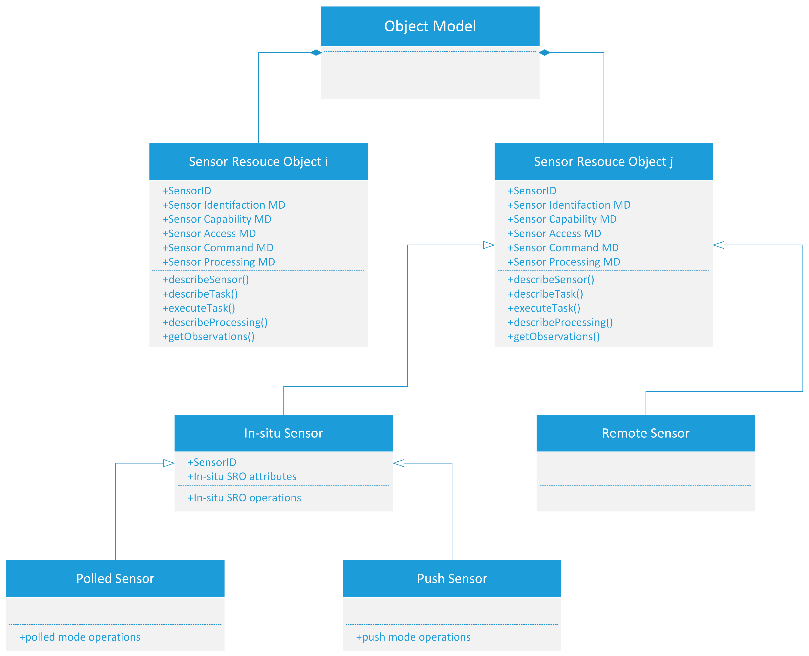
2.2.1. Sensor Resource Object

The proposed object model (OM) considers every seafloor observatory sensor as an independent object, the attributes and operations of which fully cover the four categories of sensor information for sensor control logic as mentioned above. The object model is conceptually a set of sensor resource objects (SRO) designed with object-oriented methods, the basic notions of which are illustrated in Figure 2, such as composition and specialization [32]. Each SRO represents a particular type of sensor and the OM can be expressed in the following mathematical formula:
OM = {SRO1, SRO2, …, SROn}
As a sensor can measure the environment either in situ or remotely based on its characteristics, in situ sensor and remote sensor are defined as two SRO subclasses for the object model versatility [33]. This study focuses mainly on the in situ sensor subclass, which makes up a large majority of seafloor observatories. The SRO class encapsulates three basic elements, namely, SensorID, resource attributes (RA), and resource operations (RO). This can be expressed with Equation (2):
SRO = {SensorID, RA, RO}
In the equation, SensorID identifies the uniqueness of the SRO while RA and RO are respectively a set of attributes and operations the SRO encapsulates. Based on the previous sensor information description for sensor control logic, the RA of the SRO is grouped into five metadata sets (MD) expressed as follows:
RA = {MDI, MDCP, MDA, MDCM, MDP}
where MDI is the sensor identification metadata set, MDCP is the sensor capability metadata set, MDA is the sensor access metadata set, MDCM is the sensor command metadata set, and MDP is the sensor processing metadata set. Each metadata set contains a group of associated metadata elements detailed in Section 2.2.2. With the metadata elements of the RA acted as parameters, the RO of the SRO mainly includes describeSensor(), describeTask(), executeTask(), describeProcessing(), and getObservations().
SROis = {SensorID, RAis, ROis}
Based on the above illustration, the in situ sensor resource object (SROis) can be expressed as Equation (4). The attributes (RAis) and operations (ROis) of the SROis are respectively discussed in detail in the following sections, combined with which the seafloor observatory sensor control logic is completely described and implemented.

2.2.2. Attributes of the In Situ Sensor Resource Object

As stated above, the RAis of the SROis is grouped into five metadata sets (MD; see Figure 2) that fully cover the information requirements for seafloor observatory sensor control logic. MDI includes attributes related to sensor identification such as sensorName, sensorType, sensorPlatform, and sensorNode. MDCP is comprised of metadata elements that describe sensor observation capabilities, including sensorGeolocation, sensorQuality, observationParameter, measurementSpecification, and applicationRange. MDA specifies how to access a seafloor observatory sensor with information like sensorIP, sensorPort, communicationConfiguration, sensorInterface, and responsibleCenter. MDCM provides the metadata about sensor commands in terms of commandDocumentation and commandConfiguration, based on which the in situ observatory sensor is controlled in a dynamic way in accordance with real-time data acquisition demands. MDP includes attributes on sensor observations and related data processing such as observationValidTime, datafile, database, and processingDocumentation.
Extensible Markup Language (XML) is a markup language issued by the World Wide Web Consortium for data representation and exchange. Documents encoded using XML support tree storage structure and deep nested expression with custom tags and elements. An XML document is thus designed as the information carrier to describe the SROis attributes listed in Table 1. The document consists of a set of tags that are one-to-one mapped to the above metadata sets and elements of SROis, the instantiation of which is based on every concrete SROis instance with the unique RAis. In this way, the XML elements and constraints of the document fully describe the RAis and the seafloor observatory sensor control logic.

2.2.3. Operations of the In Situ Sensor Resource Object

Data acquisition is the process of collecting measurements from various observatory sensors, which is coordinated by sending control commands to in situ sensors in accordance with dynamic observation demands [24]. Modes of data acquisition generally fall into two categories, namely, push mode and polled mode [34]. Push mode applies to sensors that can be scheduled to autonomously measure and return the observed data until new configuration commands arrive from the remote control system. Polled mode means that the remote control system has to dictate when a sensor measurement is made, in which case the in situ sensor waits for the control command to execute the measurement and send the sensed data back.
In terms of designing the ROis of the SROis, both data acquisition modes are taken into consideration and all types of SROis instances maintain the five operations for sensor control as stated above. Table 2 lists the ROis and logical structure of the proposed SROis.
The listed five operations of the ROis are further described as follows.
  • describeSensor(): The MDi served as input parameters for this operation includes the MDI and the MDCP. This operation outputs the information of SROis identification and observation capabilities, which specifies the sensor measurement.
  • describeTask(): The MDi input of this operation is the MDA and the MDCM. The output of this operation is the SROis interface information, describing the way to access and control the in situ observatory sensor.
  • executeTask(): This is the core operation for sensor control and data acquisition. With the communication and command configuration respectively from the MDA and MDCM input, this operation makes the observatory sensor measure the environment in accordance with observation demands.
  • describeProcessing(): The MDi served as input parameters for this operation refers to the MDP. The output of this operation is mainly the processing documentation, explaining how to interpret and analyze the raw observation data.
  • getObservations(): The MDi input of this operation is the MDP, based on the attributes of which the operation returns either the datafile information for raw data or the database information for interpreted data and data products.

3. Seafloor Observatory Sensor Control Experiment

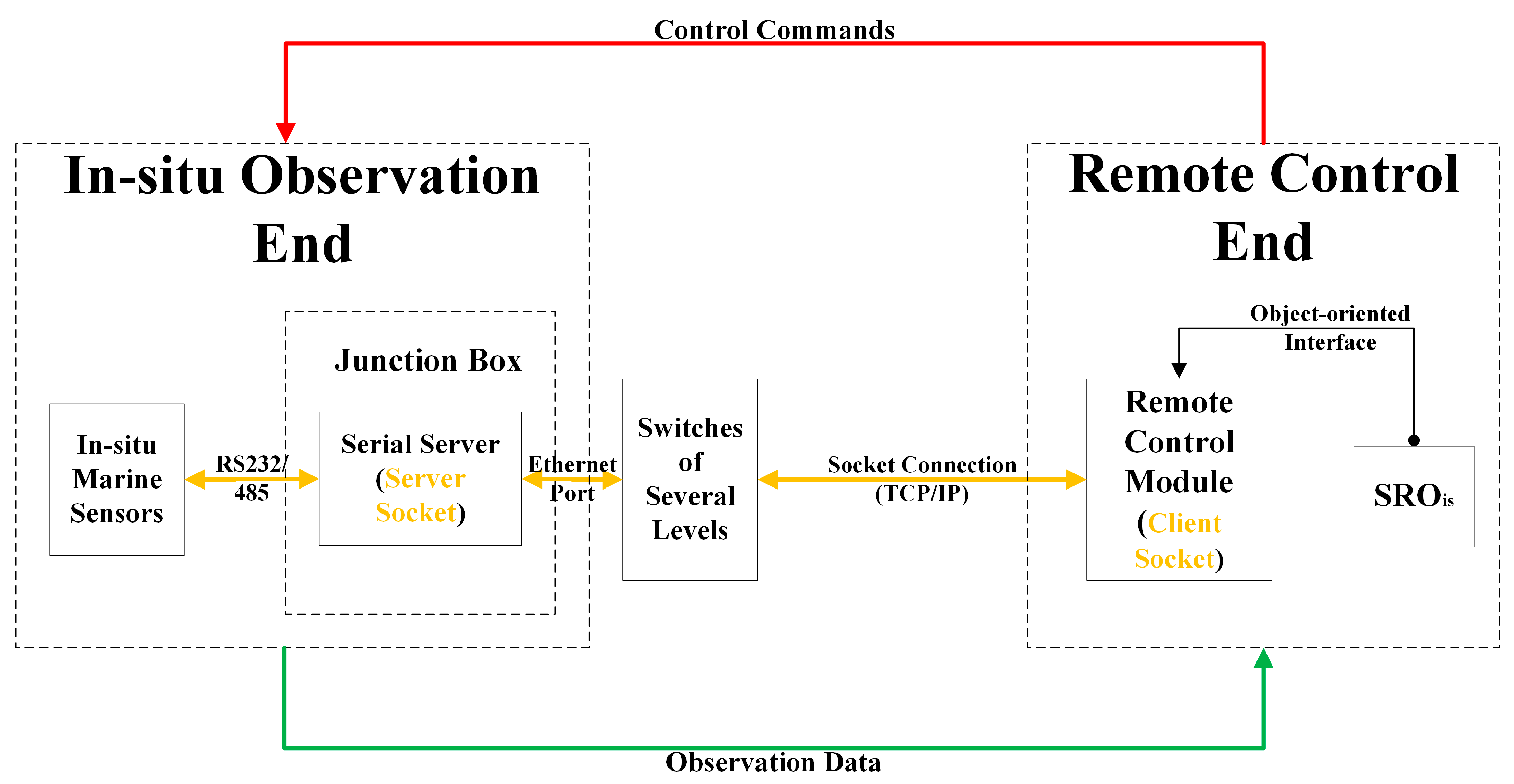
3.1. Model-Based Sensor Control Architecture

Based on the object model, a sensor control architecture is proposed for seafloor observatory networks in the East China Sea (Figure 3). This information-oriented architecture is structured into the in situ observation end and the remote control end, and it contains two classes of information flow. The flow of observation data (the green one) consists of the scientific data and the engineering data measured by various observatory sensor equipment, while the flow of control commands (the red one) stands for different control commands sent to in situ sensors according to real-time observation demands.
An optic fiber Ethernet using TCP/IP protocol is employed as the remote communication link between the in situ observation end and the remote control end, given that the optic fiber communication has high transmission rate and large capacity while the TCP/IP protocol provides a robust and reliable data transmission. A serial communication of RS232/485 is adopted in situ for the junction box and various sensors attached. This enables observatory sensors to receive and send data from and to any platform or system with Internet connectivity, of which the IP and port identification particularly forms the basis for remote sensor control.
A client–server (C/S) architecture for seafloor observatory sensor control is proposed with two considerations: one is that C/S architecture is characterized by strong interaction capabilities, which is more suitable for the frequent interoperation and huge data transmission of seafloor observatories; the other is that C/S architecture better guarantees information security, which is a necessity of seafloor observatories. The messaging mechanism of the C/S architecture is illustrated in Figure 3, of which the client is the remote control module and the server is the in situ junction box with sensors attached. In view of the fact that one IP and port pair corresponds uniquely with one observatory sensor, the remote control module conducts addressing and sends a socket connection request using the remote communication link until the in situ junction box detects and accepts the request. Once the socket connection is established, the remote control module sends various commands to dynamically control the working state of all undersea sensors and observatory infrastructure (illustrated as the red information flow). The junction box allocates the received commands to specific sensors and responds with sensed scientific data or engineering data, which are reversely transmitted to the remote control module for subsequent data processing (illustrated as the green information flow). This also completes the close-loop communication and control between the two ends of this architecture, in the process of which the SROis contributes to modelling and controlling observatory sensors in a dynamic way as detailed in Section 3.2.

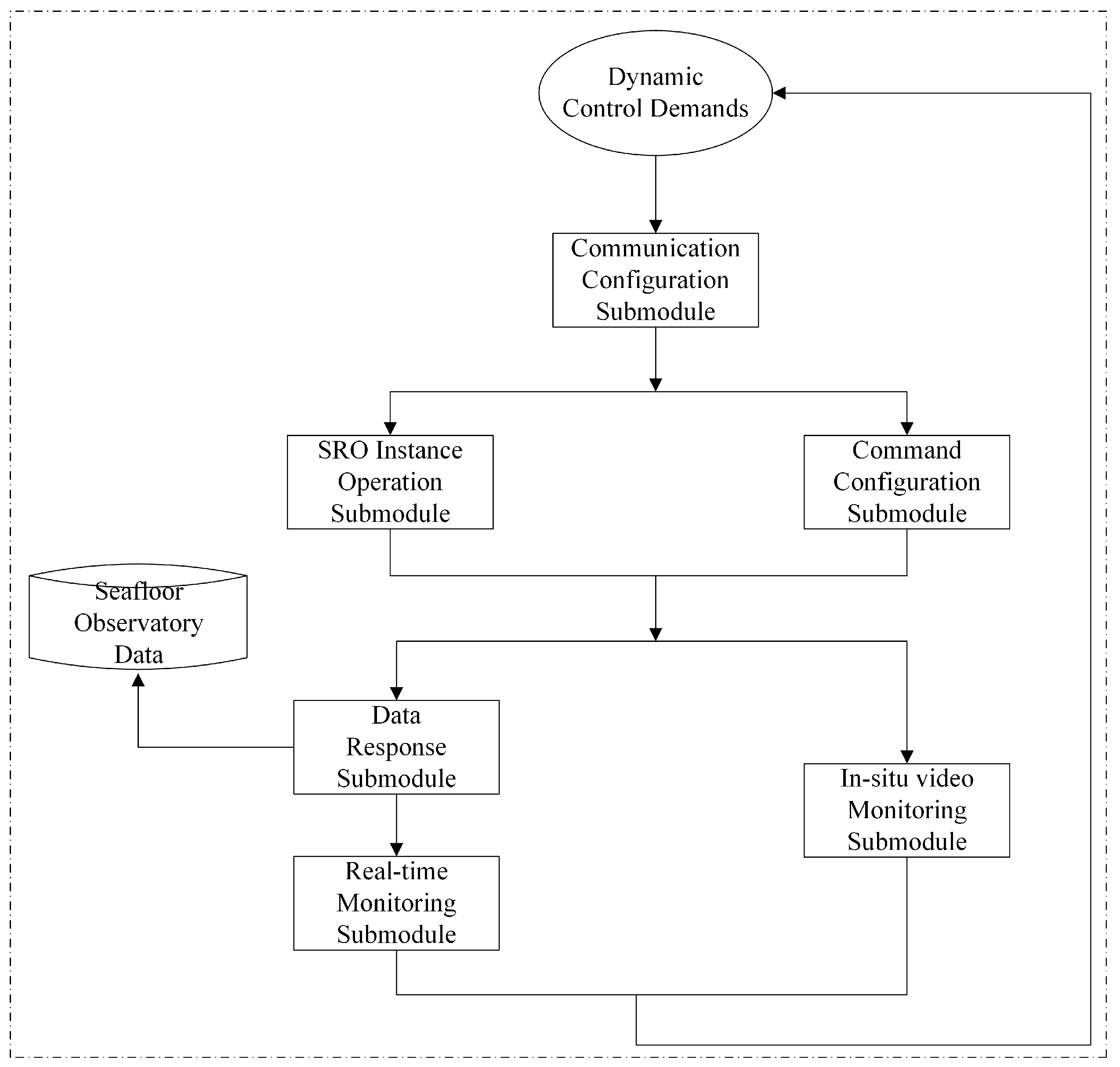
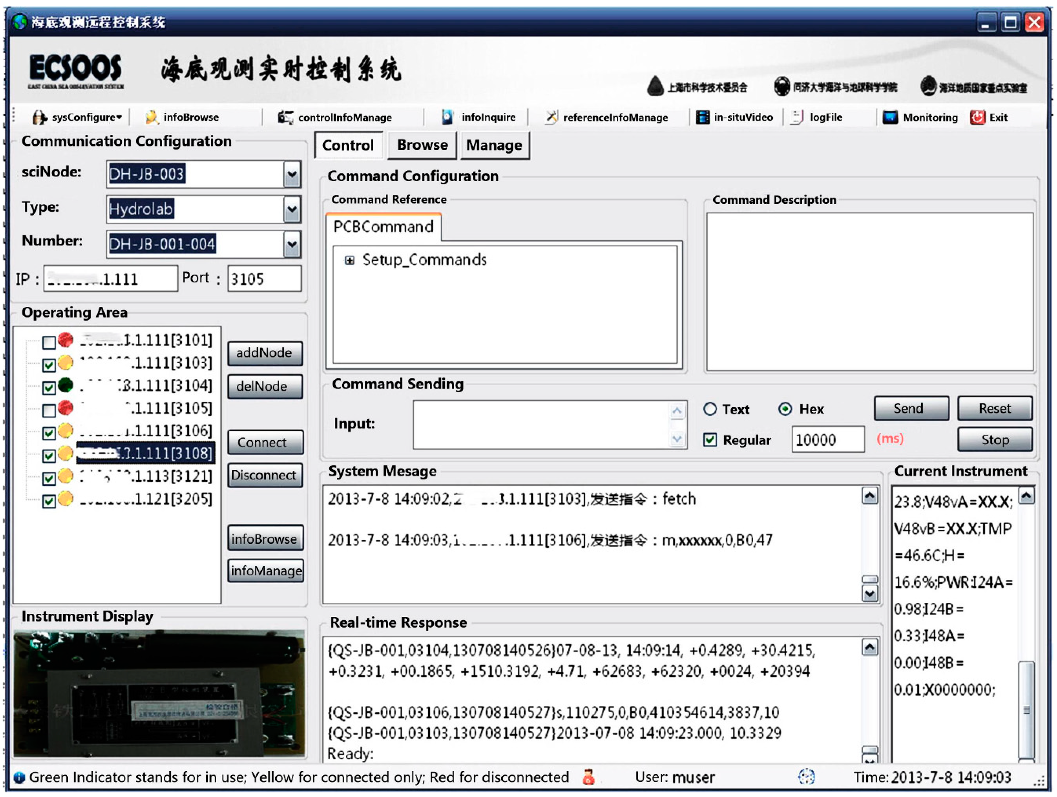
3.2. Prototype System Implementation

With the model-based architecture proposed, a control system for the East China Sea seafloor observatories (ESOCS) is implemented as a web-based and module-integrated prototype system. Given the configuration principle that modules are randomly combined [35], a smart serial server is introduced as the server component in the in situ junction box for socket listening and bidirectional data transfer. The serial server also completes the transparent protocol conversion between serial interface and network transmission, which enables observatory sensors to be interfaced and networked in a dynamic way and contributes to the plug-and-play sensor control at the in situ end. In this case ESOCS is mainly implemented with the NET framework as the client component, of which the remote control module in Figure 3 is the core module.
As mentioned in Section 2.2, the attributes of SROis fully cover the information requirements for seafloor observatory sensor control logic while the operations of SROis take both data acquisition modes into consideration. The SROis thus enables observatory sensors to be modeled and operated in a dynamic way and contributes to the plug-and-play sensor control at the remote end. The SROis instances act as the agent of undersea observatory sensors and are displayed as tree nodes centrally managed in the main interface, based on the RAis and ROis of which the remote control module is implemented as in Figure 4.
As illustrated above, the communication configuration submodule firstly refers to the dynamic control demands and loads the IP and port information of the undersea sensor to be controlled in the main interface by the SROis instance. The SRO instance operation submodule then creates a socket communication endpoint, establishes remote connection to the in situ junction box and corresponding sensor, and combines with the command configuration submodule to send commands to the specified sensor for controlling its working state, all the while still based on the attributes and operations of the SROis instance. Meanwhile the data response submodule initially displays and backs up all the received raw data from seafloor observatory sensor equipment via the SROis instance, and hands them to the real-time monitoring submodule. Combined with the in situ monitoring video, the data interpreted and analyzed by the real-time monitoring module conversely contribute to dynamic control demands and complete the close-loop information flow of the remote control module.
In order to monitor the real-time status of every SROis instance corresponding to in situ sensors, some additional implementations of the remote control module are highlighted as follows. The status indicator concept is firstly implemented for monitoring the working state of observatory sensors. As for each SROis instance added as a tree node to the main interface, an algorithm is written to indicate its current state with Indicators of three colors. Conventions are applied that a Red Indicator stands for disconnected, while a Yellow Indicator and a Green Indicator respectively stands for connected only and connected as well as responded with data. In addition, an automatic connection algorithm is developed with the block mode of socket to traverse and determine the network connection status of all SROis instances. If a sensor is accidentally disconnected and still demands real-time control, the module automatically reestablishes the socket connection and regains the interoperation of both the last sent control commands and the responded observation data.
The remote control module and other modules are implemented and integrated as ESOCS, the main interface of which is shown in Figure 5. The test and application of ESOCS are described in the following section.

3.3. Test and Appication

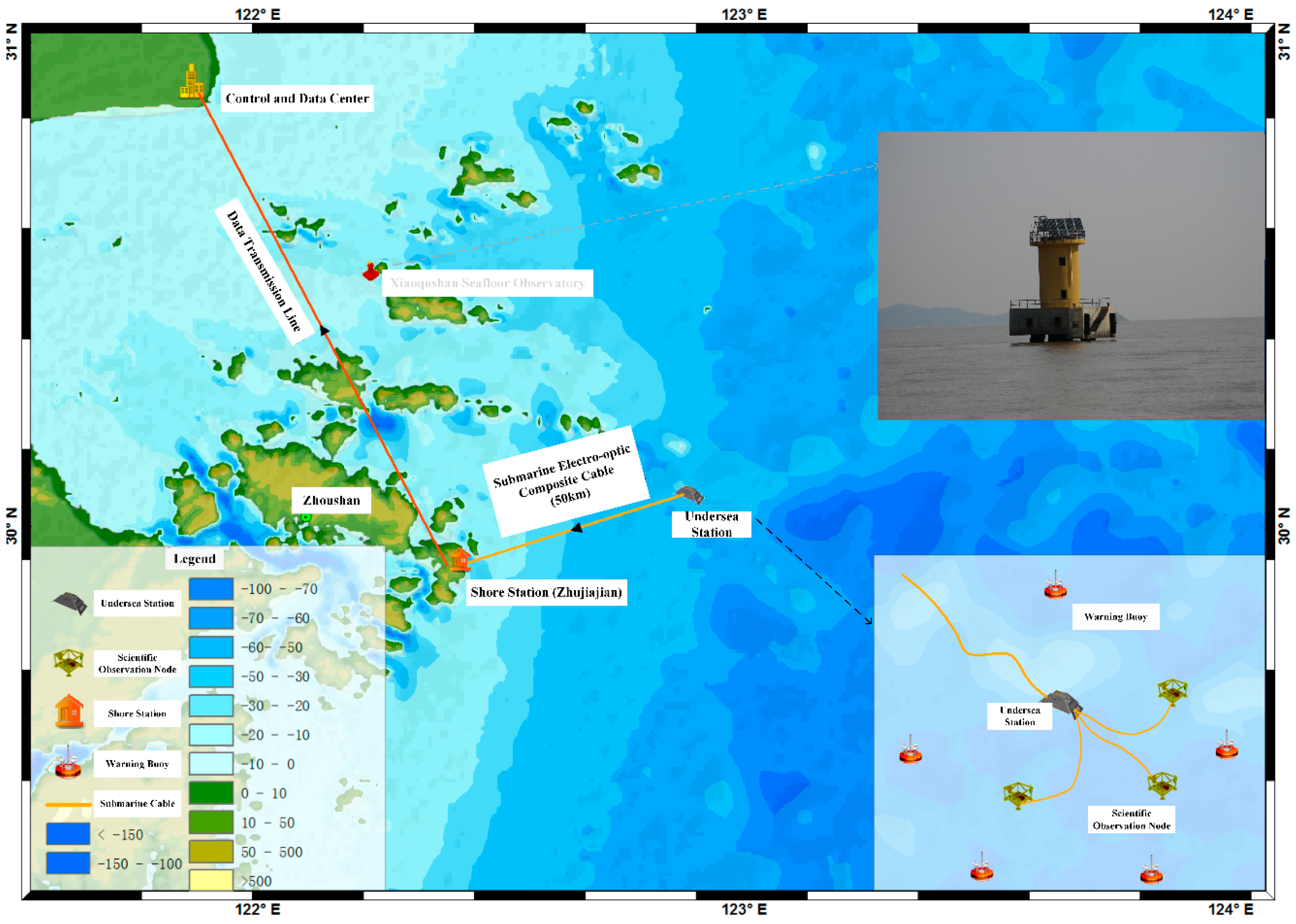
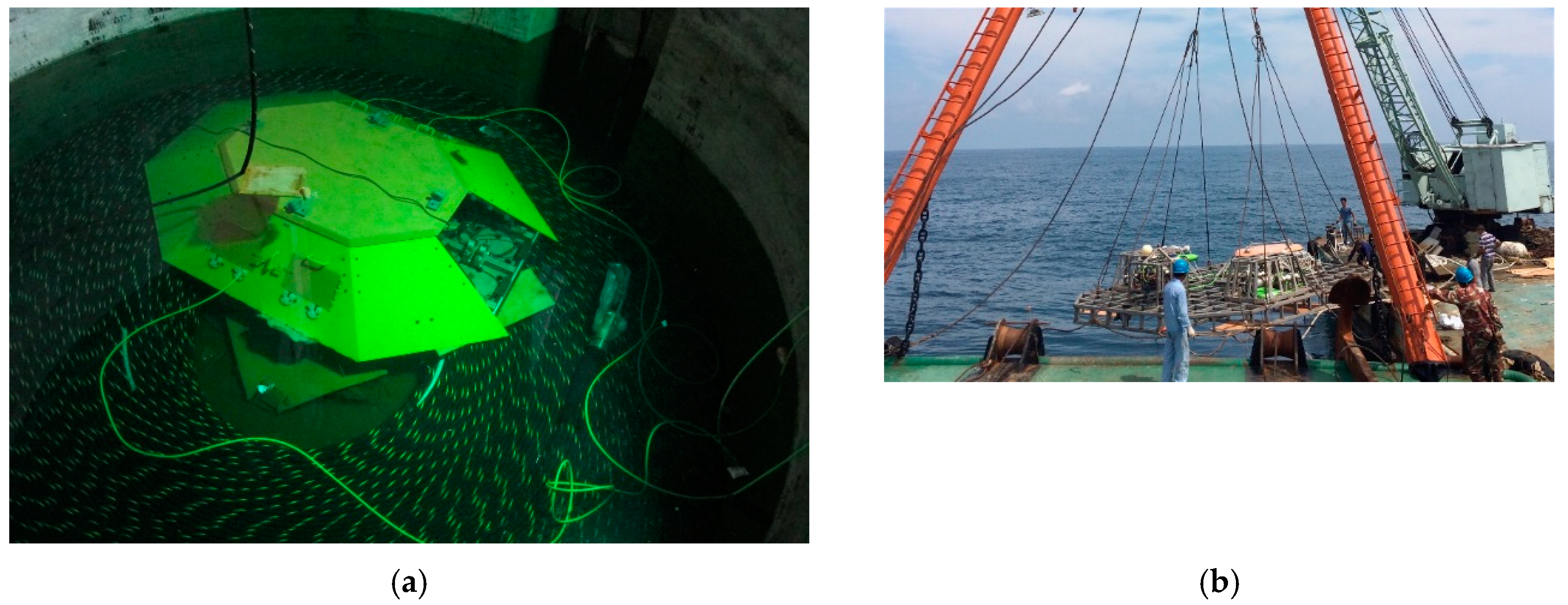
3.3.1. Experimental Scenario: The East China Sea Experimental Seafloor Observatory

Overall, the East China Sea Ocean Observation System (ECSOOS) is comprised of two observatories. The Xiaoqushan Seafloor Observatory is the first part of ECSOOS, which was originally established as a coastal observatory in 2009 and upgraded in 2013 to serve as an integrated observation platform and test bed for oceanographic instrumentation [20]. As the second part of ECSOOS, the East China Sea Experimental Seafloor Observatory (ECSESO) is a cabled seafloor observatory co-funded by the National High-tech Research and Development Plan and the Shanghai Science and Technology Commission. Located northeast of Zhujiajian Island, ECSESO aims to develop key technologies to construct and protect cabled seafloor observatories in the shallow sea with high turbidity, confluent currents, and frequent activities of marine fishery.
ECSESO is comprised of five parts, namely, three scientific observation nodes, an undersea station, a 50 km submarine electro-optic composite cable, a shore station, and a control and data center (in Figure 6). Every scientific observation node is fitted with one junction box and several marine sensors (Table 3), which are essential for real-time and continuous data acquisition. The undersea station resolves the seafloor observatory power supply and network communication in combination with the junction box, in which process the transmitted 2 kV high voltage is converted into usable voltage range for in situ sensors and all the serial sensors are connected to the Internet network for bidirectional data transmission. Sited at the Zhujiajian Island, the shore station is formed with systems of photoelectric separation and protection, power supply, and data transmission and cache. The control and data center is charged with real-time sensor control and data acquisition as well as dynamic data processing, ensuring a stable operation of the whole observatory network.
ECSESO was first deployed in August 2015 after the routing selection, during the operation period of which the early waring buoy and the cable were damaged by trawlers many times. An overhaul engineering of ECSESO started in September 2017 and ended in February 2018, since when ECSESO operated successfully until the project was completed. As for supporting the whole ECSESO operation, the implemented ESOCS played a key role in the real-time observatory sensor control and data acquisition.

3.3.2. Prototype System Test and Application

An individual module test was first carried out on the remote control module and other modules of ESOCS, during which process one junction box and a few marine sensors were connected on the laboratory bench and simulated as the in situ observation end. This stage of test guaranteed that each module met the functional requirements of integrity, reliability, and adaptability for changing demands. Next, all modules were integrated into ESOCS for a tank test at Zhongtian Technology Submarine Cables Co., Ltd. The tank test fully conformed to the ECSESO network scheme, in the testing process of which one undersea station and three scientific observation nodes were assembled and respectively placed in the testing pool before the power was supplied via a submarine electro-optic composite cable (as shown in Figure 7a). ESOCS was run for remotely connecting with underwater sensor equipment and the prototype system was continuously debugged under both normal operation and boundary conditions. The tank test lasted for over one month and the prototype system maintained an uninterrupted operation, proving that ESOCS complied with all expected requirements for seafloor observatory sensor control and data acquisition.
ESOCS was finally conducted a shallow sea trial near Zhujiajian Island before servicing ECSESO (as shown in Figure 7b). ESOCS was deployed at the control center and remotely debugged with observatory sensor equipment under the sea, in which process all parts of the observatory proved to perform well. During the service, ESOCS was consistently guaranteeing the whole observatory operation and performing consistently with all the project requirements: (i) all the observation data were acquired and interpreted in a real-time manner, and were stored with associated metadata; (ii) all the in situ sensor equipment were dynamically controlled, with extendibility of hardware expansions and software upgrades; (iii) all the observatory facilities and marine environment were monitored online, and responded with predefined control rules for detected events; and (iv) the sensor control architecture enabled interactions with other ocean observation platforms and sensor systems.
Given the environment hostility such as high turbidity, confluent currents, and frequent marine fishery activities of the East China Sea toward undersea sensor equipment, the monitoring of the proper function of observatory components and the control of the measuring process are thus critical. In response to the changing environmental conditions, the sensor control capabilities of ESOCS guarantee that multidisciplinary observation parameters are dynamically acquired in a consistent way. Citing the observatory operation period between February 2018 and August 2018 as an instance, the prototype system acquired 400 thousand pieces of velocity data from AWAC sensor as well as 2 million and over 1.7 million pieces of data, respectively, from LISST-100X sensor and SBE 26 sensor. Observations of the aforementioned three sensors were also used to monitor the variation of suspended particles in the bottom waters in a case study [36]. To be specific, two initial periods of the observatory operation cycles, in 2015 and 2018, were selected to study the diurnal and seasonal variations including particle size distribution (PSD) and volume concentration (Figure 8). The floc size and concentration of suspended particles not only significantly influence the optical properties of the sea water and the marine ecological environment, but also determine the settling velocity that conversely plays an important role in the transportation, deposition and interaction of sediments in the water column. The 32 bins measured by the LISST-100X sensor were reclassified into three categories as single grains (<36 µm), microflocs (36–133 µm), and macroflocs (>133 µm) for investigating how different sized particles varied with the water currents. Time series of the particle diameters of D50 (median particle size, where the cumulative concentration reached 50% of the total) as well as D25 and D75 were also calculated. The power law model was tested to describe the PSD variability based on the field data, which proved to be applicable to estimating the particle number in each particle size with the same optimal reference D0 located at 63.11 µm. The tidal harmonic analysis by UTide Matlab functions indicated that diurnal dynamics of sediments were mainly due to the resuspension and advection induced by the tide, and particle concentration was lower in the dry season (February) than in the flood season (September). The widespread presence of macroflocs was found using the two seasonal data in the case study, which further demonstrated the practical performance of ESOCS in terms of observatory data provision and usage.

4. Discussion

The object model proposed in this paper considers every seafloor observatory sensor as an independent sensor resource object (SROis), the attributes (RAis) and operations (ROis) of which contribute to standardizing the process of observatory sensor control and data acquisition. By analyzing the information requirements for sensor control logic, the RAis is designed to fully cover the four information categories of sensor communications, sensor commands, sensor parameters, and sensor observations. The metadata elements of RAis not only build the information model for identifying and describing observatory sensors, but also serve as the input parameters of ROis for operating and controlling in situ sensors. The operations of ROis are thus designed to remotely control seafloor observatory sensors in a dynamic way, in which order the describeSensor() and describeTask() operations are firstly called to get sensor access and control instructions before the executeTask() operation is called to control the working state of the sensor. Afterwards the getObservations() and describeProcessing() operations are respectively called for data acquisition and data processing, which in return give a reference for generating dynamic control demands. Based on the SROis, the prototype control system is designed, implemented, and successfully deployed in the experimental scenario. The feasibility of the object model is thereby demonstrated for in situ sensor control and observatory data acquisition.
In the proposed object model, the set of sensor resource objects (SRO) are designed with the object-oriented approach and are thus characterized by the basic notions of encapsulation, inheritance, and polymorphism. In this way, the attributes and operations of SRO can be customized to describe more types of seafloor observatory sensors and execute more generalized closed loop control processes from data acquisition to decision making. With the SRO customized and instantiated, the sensor control architecture and the prototype system can accordingly adapt to a broad range of ocean observation sensor systems for real-time sensor control and data acquisition. This conversely demonstrates the versatility and extensibility of the object model.
The object model-based sensor control architecture is implemented with the prototype system (ESOCS), specially characterized by its plug-and-play enablement. Compared with related advances such as Oceans 2.0 and EGIM proposed in the literature, the plug-and-play enablement demands no extra protocol (e.g., IEEE 1451 and PUCK) for sensor identification and communication at the in situ observation end. On the one hand, the in situ junction box is introduced as the server component to complete the transparent protocol conversion between serial interface and network transmission, which maximizes the range of observatory sensors that are dynamically interfaced and networked without extra requirements for the hardware or firmware upgrade. On the other hand, the remote control module is programmed to dynamically create and operate the SRO instances acting as the agent of in situ sensors, in which way the control operations performed on newly configured or reconfigured observatory sensors have no inference with other sensor equipment or current operations of the whole observatory. Regarding this advantage, the plug-and-play enablement contributes to a more universal and flexible observatory sensor integration and control. Given the aforementioned versatility and extensibility of the object model, the plug-and-play enablement owns another advantage in its data processing expansion as the SRO operations can be customized to execute more generalized sensor control processes from sensing and cognition to decision making and execution. The expansion of the plug-and-play enablement contributes to a more comprehensive and effective observatory data processing and management. ESOCS, thus, demands no additional design for controlling new sensors and enables the plug-and-play at the system level. As shown in Section 3.3, ESOCS has proved its practical performance through a series of tests and applications. The case study demonstrates potential observatory data usage, further proving the contribution of ESOCS to the whole observatory outcome from a data provision and usage standpoint. The controllable seafloor observatory therefore facilitates scientific research and engineering practice and is widely beneficial to the ocean community. Consequently, the proposed sensor control architecture and prototype implementation can provide reference value for seafloor observatory networks and related ocean observation sensor systems.
All the contributions discussed above provide a complete demonstration for the design, development, and deployment of a seafloor observatory sensor control system. With the successful test and application of the prototype system, these contributions are thus feasible to solve the issue of seafloor observatory sensor control in a standardized and dynamic way. Future work includes the object model optimization for a more generalized closed loop control process and the remote sensor class of the SRO.

5. Conclusions

An object model is described that acts as a standard method for seafloor observatory sensor control. The sensor resource object (SRO) is designed, based on the attributes and operations of which the sensor control architecture is proposed with plug-and-play enablement. The feasibility of the model-based architecture is implemented with the prototype control system, namely, ESOCS. ESOCS has presented satisfactory practical performance through a series of tests and applications. Through this study, we demonstrate that the object model design and implementation are of benefit to seafloor observatory science.

Author Contributions

Conceptualization, Y.Y.; methodology, Y.Y. and H.X.; software and validation, Y.Y. and C.X.; writing—original draft, Y.Y.; and writing—review and editing, Y.Y., H.X., and C.X. All authors have read and agreed to the published version of the manuscript.

Funding

This research was supported in part by Fundamental Research Funds for the Central Universities under Grant No. 22120180003, State Key Laboratory of Marine Geology (Tongji University) Funds under Grant No. MG20180302, Shanghai Sailing Program under Grant No. 18YF1424100, and the National High-tech Research and Development Program under Grant No. 2012AA09A407.

Acknowledgments

The authors thank other research group members for their participation in this study.

Conflicts of Interest

The authors declare no conflict of interest.

Abbreviations

ECSESOEast China Sea Experimental Seafloor Observatory
ECSOOSEast China Sea Ocean Observation System
EMSOEuropean Multidisciplinary Seafloor and water-column Observatory
ESOCSThe control system for seafloor observatories in the East China Sea
MDMetadata sets
OMObject Model
ONCOcean Networks Canada
OOIOcean Observatories Initiative
RASensor Resource Attribute
RAisIn situ sensor Resource Attribute
ROSensor Resource Operation
ROisIn situ sensor Resource Operation
SROSensor Resource Object
SROisIn situ Sensor Resource Object

References

  1. National Research Council. Illuminating the Hidden Planet—The Future of Seafloor Observatory Science, 1st ed.; National Academies Press: Washington, DC, USA, 2000; pp. 1–160.
  2. National Science Foundation. Ocean Sciences at the New Millennium, 1st ed.; Geosciences Professional Services, Inc.: Washington, DC, USA, 2001; pp. 1–152.
  3. Favali, P.; Beranzoli, L. Seafloor Observatory Science: A Review. Ann. Geophys. 2006, 49, 515–567. [Google Scholar]
  4. Ruhl, H.A.; André, M.; Beranzoli, L.; Çağatay, M.N.; Colaco, A.; Cannat, M.; Dañobeitia, J.J.; Favali, P.; Géli, L.; Gillooly, M.; et al. Societal need for improved understanding of climate change, anthropogenic impacts, and geo-hazard warning drive development of ocean observatories in European Seas. Prog. Oceanorg. 2011, 91, 1–33. [Google Scholar] [CrossRef] [Green Version]
  5. Wang, P.X. Current Development in Marine Science and Technology: A Retrospect. Adv. Earth Sci. 2011, 26, 644–649. [Google Scholar]
  6. Rountree, R.; Aguzzi, J.; Marini, S.; Fanelli, E.; Juanes, F. Towards an optimal design for ecosystem-level ocean observatories. Oceanogr. Mar. Biol. 2020, 58, 235–286. [Google Scholar]
  7. Danovaro, R.; Fanelli, E.; Aguzzi, J.; Billett, D.; Carugati, L.; Corinaldesi, C.; Dell’Anno, A.; Gjerde, K.; Jamieson, A.J.; Kark, S.; et al. Ecological indicators for an integrated global deep-ocean strategy. Nat. Ecol. Evol. 2020, 4, 181–192. [Google Scholar] [CrossRef] [PubMed]
  8. Glen, S.M.; Dickey, T.D.; Parker, B.; Boicourt, W. Long-term real-time coastal ocean observation networks. Oceanography 2000, 13, 24–34. [Google Scholar] [CrossRef]
  9. Duennebier, F.K.; Harris, D.W.; Jolly, J.; Auerbach, J.C.; Jordan, R.; Copson, D.; Stiffel, K.; Babinec, J.; Bosel, J. HUGO: The Hawaii Undersea Geo-Observatory. IEEE J. Ocean. Eng. 2002, 27, 218–227. [Google Scholar] [CrossRef]
  10. Massion, G.; Raybould, K. MARS: The monterey accelerated research system. Sea Technol. 2006, 47, 39–42. [Google Scholar]
  11. Cowles, T.; Delaney, J.; Orcutt, J.; Weller, R. The Ocean Observatories Initiative: Sustained Ocean Observing Across a Range of Spatial Scales. Mar. Technol. Soc. J. 2010, 44, 54–64. [Google Scholar] [CrossRef]
  12. Monna, S.; Falcone, G.; Beranzoli, L.; Chierici, F.; Cianchini, G.; De Caro, M.; De Santis, A.; Embriaco, D.; Frugoni, F.; Marinaro, G.; et al. Underwater geophysical monitoring for European Multidisciplinary Seafloor and water column Observatories. J. Mar. Syst. 2014, 130, 12–30. [Google Scholar] [CrossRef]
  13. Favali, P.; Chierici, F.; Marinaro, G.; Giovanetti, G.; Azzarone, A.; Beranzoli, L.; De Santis, A.; Embriaco, D.; Monna, S.; Lo Bue, N.; et al. NEMO-SN1 Abyssal Cabled Observatory in the Western Ionian Sea. IEEE J. Ocean. Eng. 2013, 38, 358–374. [Google Scholar] [CrossRef]
  14. Río, J.; Nogueras, M.; Aguzzi, J.; Toma, D.; Masmitjà, I.; Carandell, M.; Olive, J.; Martínez, E.; Artero, C.; Bghiel, I.; et al. Obsea: A decadal balance for a cabled observatory deployment. IEEE Access 2020, 8, 33163–33177. [Google Scholar]
  15. Aguzzi, J.; Albiez, J.; Flögel, S.; Rune Godø, O.; Grimsbø, E.; Marini, S.; Pfannkuche, O.; Rodriguez, E.; Thomsen, L.; Torkelsen, T.; et al. A flexible autonomous robotic observatory infrastructure for bentho-pelagic monitoring. Sensors 2020, 20, 1614. [Google Scholar] [CrossRef] [PubMed] [Green Version]
  16. Aguzzi, J.; Chatzievangelou, D.; Marini, S.; Fanelli, E.; Danovaro, R.; Flögel, S.; Lebris, N.; Juanes, F.; De Leo, F.; Del Rio, J.; et al. New high-tech interactive and flexible networks for the future monitoring of deep-sea ecosystems. Environ. Sci. Technol. 2019, 53, 6616–6631. [Google Scholar] [CrossRef] [PubMed] [Green Version]
  17. Kasahara, J.; Utada, H.; Kinoshita, H. GeO-TOC Project-Reuse of Submarine Cables for Seismic and Geoelectrical Measurements. J. Phys. Earth 1995, 43, 619–628. [Google Scholar] [CrossRef]
  18. Shinohara, M.; Kanazawa, T.; Yamada, T.; Machida, Y.; Sakai, S. New Compact Ocean Bottom Cabled Seismometer System Deployed in the Japan Sea. Mar. Geophys. Res. 2013, 35, 231–242. [Google Scholar] [CrossRef] [Green Version]
  19. Wang, K.L.; Moran, K. NEPTUNE Canada: Science, Operation, and Management. Adv. Earth Sci. 2013, 28, 521–528. [Google Scholar]
  20. Xu, H.P.; Zhang, Y.W.; Xu, C.W.; Li, J.R.; Liu, D.; Qin, R.F.; Luo, S.Q.; Fan, D.D. Coastal Seafloor Observatory at Xiaoqushan in the East China Sea. Chin. Sci. Bull. 2011, 56, 2839–2845. [Google Scholar] [CrossRef] [Green Version]
  21. Buck, J.; Bainbridge, S.; Burger, E.; Casari, M.; Casey, K.; Del Rio, J.; Metfies, K.; Fischer, P.; Heffernan, R.; Jirka, S. Ocean data product integration through innovation-The next level of data interoperability. Front. Mar. Sci. 2019, 6, 32. [Google Scholar] [CrossRef] [Green Version]
  22. Barnes, C.R.; Best, M.M.R.; Johnson, F.R.; Pautet, L.; Pirenne, B. Challenges, Benefits, and Opportunities in Installing and Operating Cabled Ocean Observatories Perspectives from NEPTUNE Canada. IEEE J. Ocean. Eng. 2013, 38, 144–157. [Google Scholar] [CrossRef]
  23. Rio, J.d.; Toma, D.M.; O’Reilly, T.C.; Bröring, A.; Dana, D.; Bache, F.; Headley, K.L.; Mànuel-Làzaro, A.; Edgington, D. Standards-Based Plug & Work for Instruments in Ocean Observing Systems. IEEE J. Ocean. Eng. 2014, 39, 430–443. [Google Scholar]
  24. Aguzzi, J.; Chatzievangelou, D.; Francescangeli, M.; Marini, S.; Bonofiglio, F.; Del Río, J.; Danovaro, R. The hierarchic treatment of marine ecological information from spatial networks of benthic platforms. Sensors 2020, 20, 1751. [Google Scholar] [CrossRef] [PubMed] [Green Version]
  25. Leadbetter, A.; Smyth, D.; Fuller, R.; O’Grady, E.; Shepherd, A. Where Big Data meets Linked Data: Applying standard data models to environmental data streams. In Proceedings of the 2016 IEEE International Conference on Big Data, Washington, DC, USA, 5–8 December 2016. [Google Scholar]
  26. Rodero, I.; Parashar, M. Data Cyber-Infrastructure for End-to-end Science: Experiences from the NSF Ocean Observatories Initiative. Comput. Sci. Eng. 2019, 22, 60–71. [Google Scholar] [CrossRef]
  27. Arnaud, B.; Chave, A.; Maffei, A.; Lazowska, E.; Smarr, L.; Gopalan, G. An Integrated Approach to Ocean Observatory Data Acquisition/Management and Infrastructure Control Using Web Services. Mar. Technol. Soc. J. 2004, 38, 155–163. [Google Scholar] [CrossRef]
  28. Liu, X.R.; Qi, F.J.; Ye, W.Q.; Song, Z.Y.; Zheng, R.E. Underwater control system of OUC-Raman instrument node for seafloor observatory network. J. Harbin Eng. Univ. 2017, 38, 1216–1222. [Google Scholar]
  29. Gao, S.Y.; Li, Z.G.; Sun, K. Design and Operational Testing of the Data Acquisition and Management System of Seafloor Cabled Observatories. J. Ocean. Tech. 2017, 36, 34–39. [Google Scholar]
  30. Yu, Y.; Xu, H.P.; Xu, C.W. A Sensor Control Model for Cabled Seafloor Observatories in the East China Sea. Sensors 2018, 18, 3027. [Google Scholar] [CrossRef] [Green Version]
  31. Yu, Y.; Xu, H.P.; Xu, C.W. A Sensor Web Prototype for Cabled Seafloor Observatories in the East China Sea. J. Mar. Sci. Eng. 2019, 7, 414. [Google Scholar] [CrossRef] [Green Version]
  32. Hu, C.L.; Li, J.; Chen, N.C.; Guan, Q.F. An Object Model for Integrating Diverse Remote Sensing Satellite Sensors: A Case Study of Union Operation. Remote Sens. 2014, 6, 677–699. [Google Scholar] [CrossRef] [Green Version]
  33. Botts, M. OpenGIS Sensor Model Language (SensorML) Implementation Specification; Open Geospatial Consortium: Wayland, MA, USA, 2007. [Google Scholar]
  34. Bello, D.S.S.; Beuzekom, M.; Jansweijer, P.; Verkooijen, H.; Visschers, J. An interface board for the control and data acquisition of the Medipix2 chip. Nucl. Instrum. Meth. A 2003, 509, 164–170. [Google Scholar] [CrossRef]
  35. Yuan, X.Y.; Niu, Y.; Yu, Q.; Zhang, X.G. Configuration Control Technologies; Publishing House of Electronics Industry: Beijing, China, 2003; pp. 1–287. [Google Scholar]
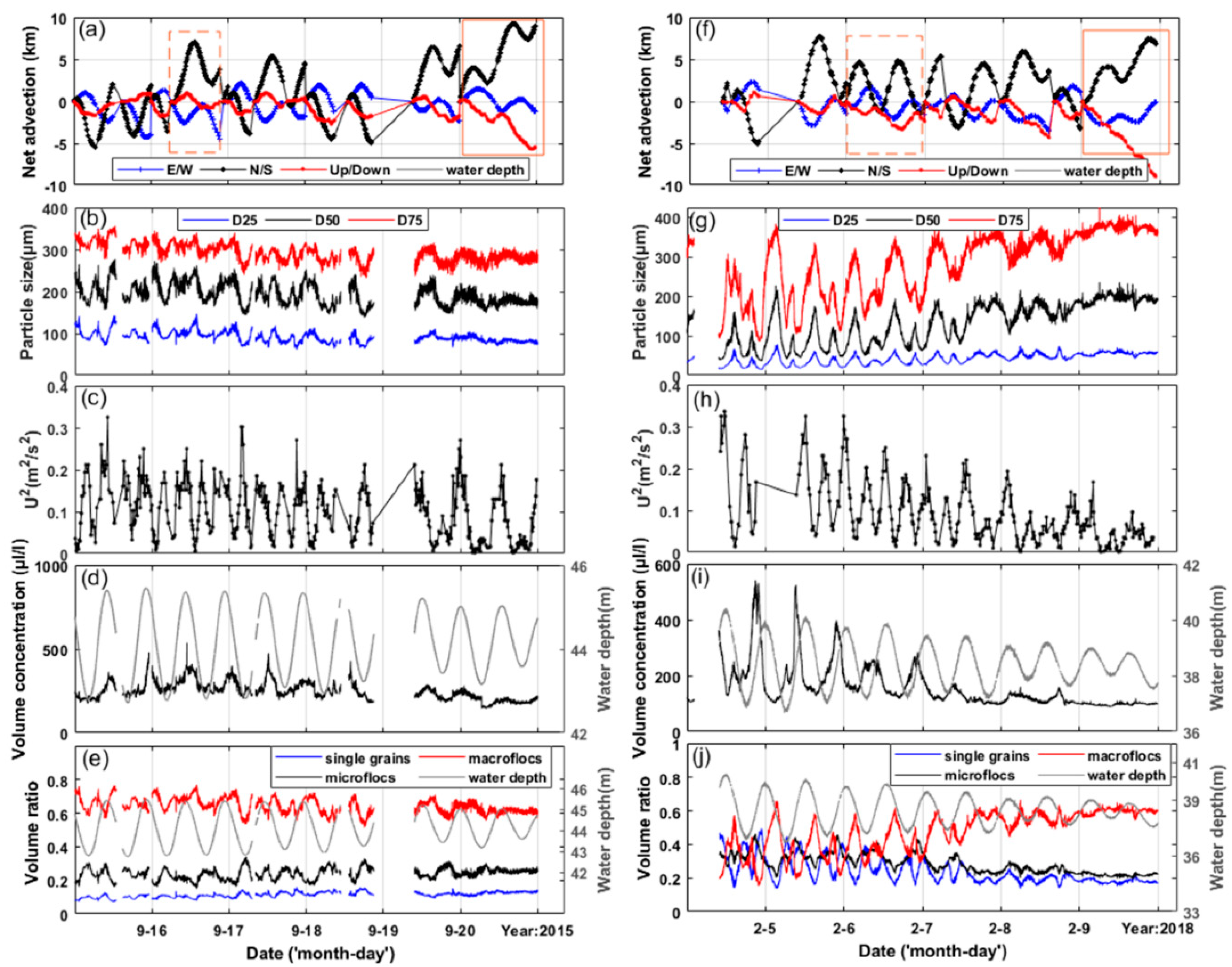
  36. Shang, D.H.; Qin, R.F.; Xu, H.P.; Xu, C.W.; Sun, K.L.; Zhou, Y.S. Variation of Suspended Particles in the Bottom Layer of the East China Sea with Data from Seafloor Observatory. Sensors 2019, 19, 5156. [Google Scholar] [CrossRef] [PubMed] [Green Version]
Figure 1. Sensor information and the observatory sensor control logic.
Jmse 08 00716 g001
Figure 2. Conceptual level of the object model.
Jmse 08 00716 g002
Figure 3. Object model-based sensor control architecture.
Jmse 08 00716 g003
Figure 4. Implementation diagram of the remote control module.
Jmse 08 00716 g004
Figure 5. Main interface of the control system for the East China Sea seafloor observatories (ESOCS).
Jmse 08 00716 g005
Figure 6. East China Sea Experimental Seafloor Observatory (ECSESO).
Jmse 08 00716 g006
Figure 7. (a) Tank test for ESOCS; (b) Shallow sea trial for ESOCS.
Jmse 08 00716 g007
Figure 8. Temporal variations in field measurements of the two observatory periods, including net advection (a,f), floc size (b,g), current stress (c,h), total volume concentration (d,i), and volume ratio of each particle category (e,j).
Jmse 08 00716 g008
Table 1. Attributes of the In Situ Sensor Resource Object.
Metadata SetMetadata Elements
MDISensor Name, sensor Type, sensor Platform, sensor Node
MDCPSensor Geolocation, sensor Quality, observation Parameter, measurement Specification, application Range
MDASensor IP, sensor Port, communication Configuration, sensor Interface, responsible Center
MDCMCommand Documentation, command Configuration
MDPObservation Valid Time, datafile, database, processing Documentation
Table 2. Operations and Logical Structure of the In Situ Sensor Resource Object.
SROis
SensorIDRAisROis
SensorIDMD iDescribe Sensor (MD i)Describe Task (MD i)Execute Task (MD i)Describe Processing (MD i)Get Observations (MD i)
MD i represents the metadata sets of the SROis attributes. Every SROis instance has a unique SensorID and five operations associated with attributes.
Table 3. ECSESO Sensors.
Observation NodeSensorObservation ParameterSampling Interval
Node 1 (Node of Shanghai Science and Technology Commission)CTD/SBE16Temperature, Conductivity, Dissolved oxygen, Depth50 s
CTD/SBE26Temperature, Conductivity, Depth10 s
LISST-100 XGranularity, Temperature10 s
AWACSeawater flow field25 min
Camera/OE14-376Real-time videocontinuous
Node 2 (Node of State Oceanic Administration)Chlorophyll Meter (SDIOI)Chlorophyll concentration5 s
CTD (SDIOI)Temperature, Conductivity, Depth, Turbidity5 s
CTD (NOTC)Temperature, Conductivity, Depth8 s
ADCP (Linkquest)Seawater flow field5 min
Camera/OE14-376Real-time videocontinuous
Node 3 (Node of National High-tech Research and Development Plan)RBR concertoTemperature, Conductivity, Depth30 s
Chlorophyll MeterChlorophyll concentration30 s
Dissolved Oxygen SensorDissolved oxygen concentration30 s
Turbidity SensorTurbidity30 s
SUNA SensorNitrate concentration5 min
HydroC PAHConcentration of polycyclic aromatic hydrocarbons5 s
CO2-Pro CVCarbon dioxide concentration30 min
Methane SensorMethane concentration10 s
ADV/Nortek Vector Current MeterSingle point velocity10 min
ADCP/WHMW300-I-UG11Profile velocity1 min
TDO-33BSeismic data0.01 s
Camera/OE14-376Real-time Videoprogram control
SDIOI represents Institute of Oceanographic Instrumentation, Shandong Academy of Sciences; NOTC represents National Ocean Technology Center.

