Numerical Simulation of Wave Interaction with Payloads of Different Postures Using OpenFOAM


Abstract
1. Introduction
2. Numerical Methods
2.1. Governing Equations
2.2. Free Surface Tracking
2.3. Waves2Foam Library and WaveFoam Solver
2.3.1. Waves2Foam Library
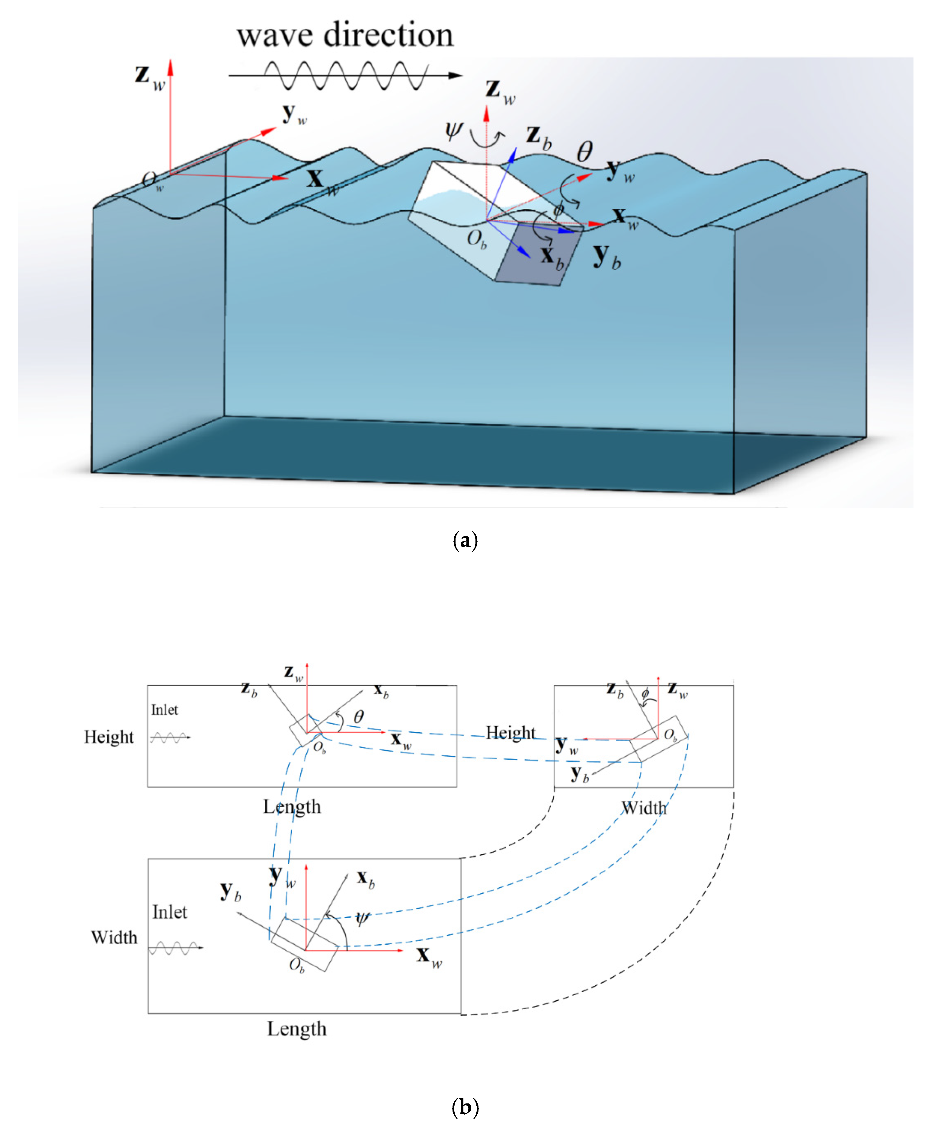
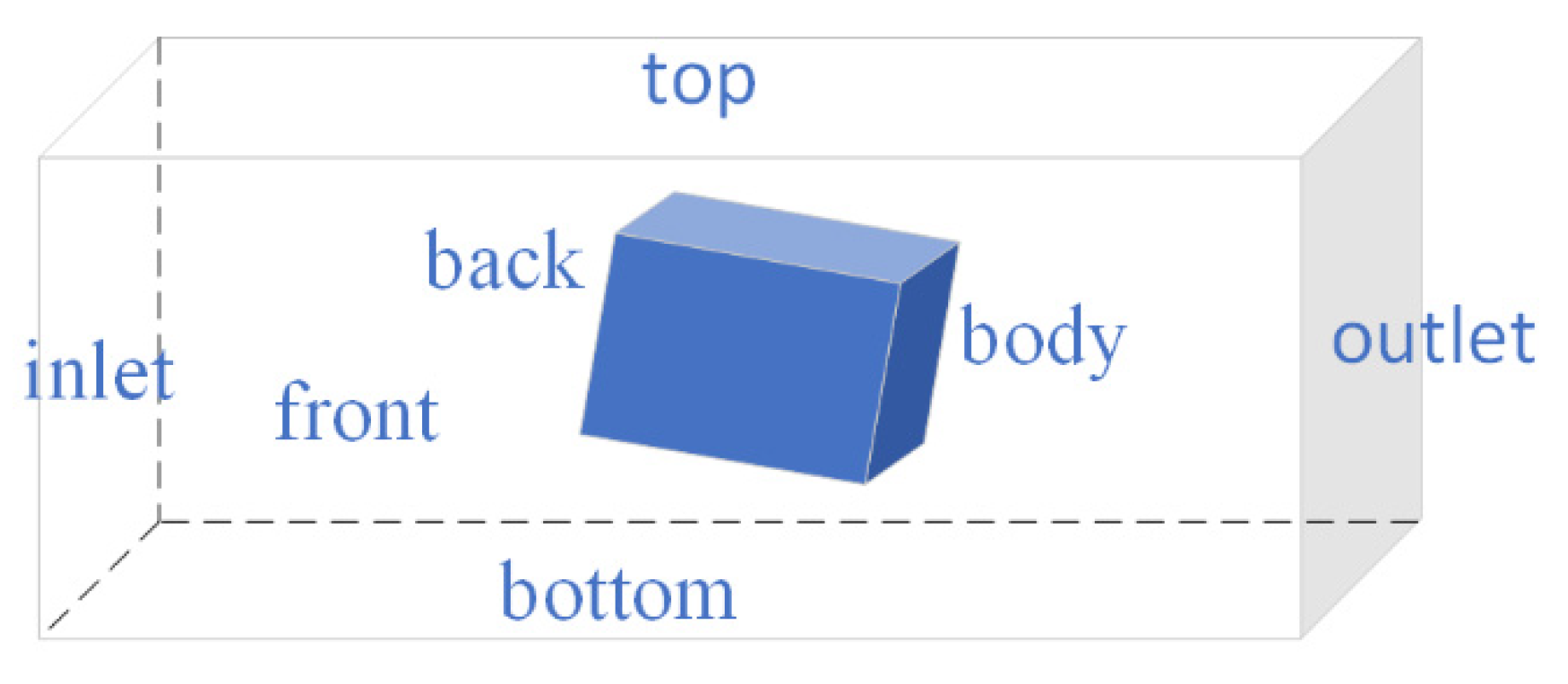
2.3.2. WaveFoam Solver and Boundary Conditions
- 1.
- Boundary conditions
- 2.
- Solving procedure
3. Comparison Against Published Data
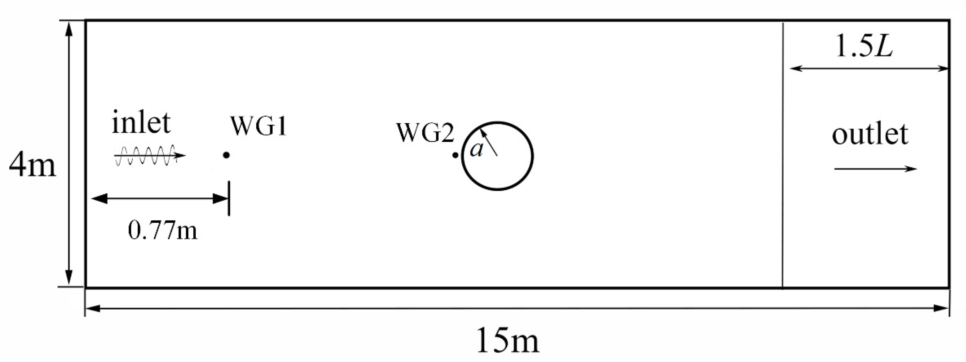
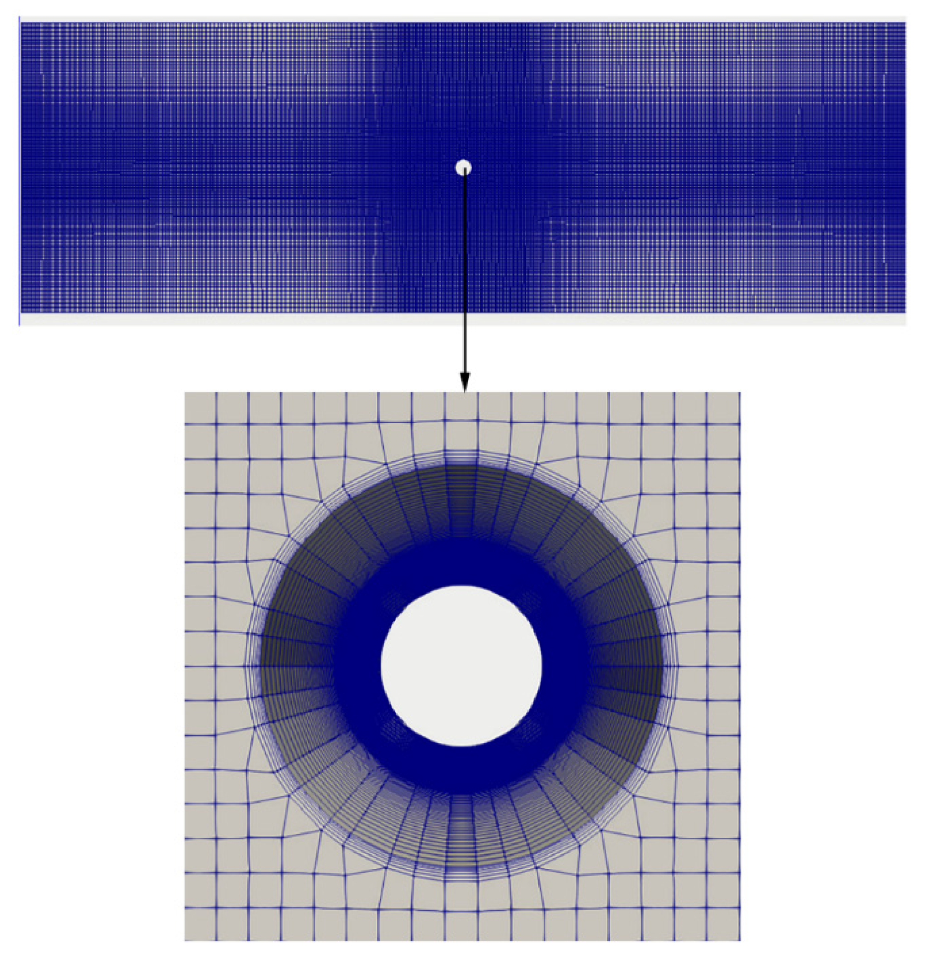
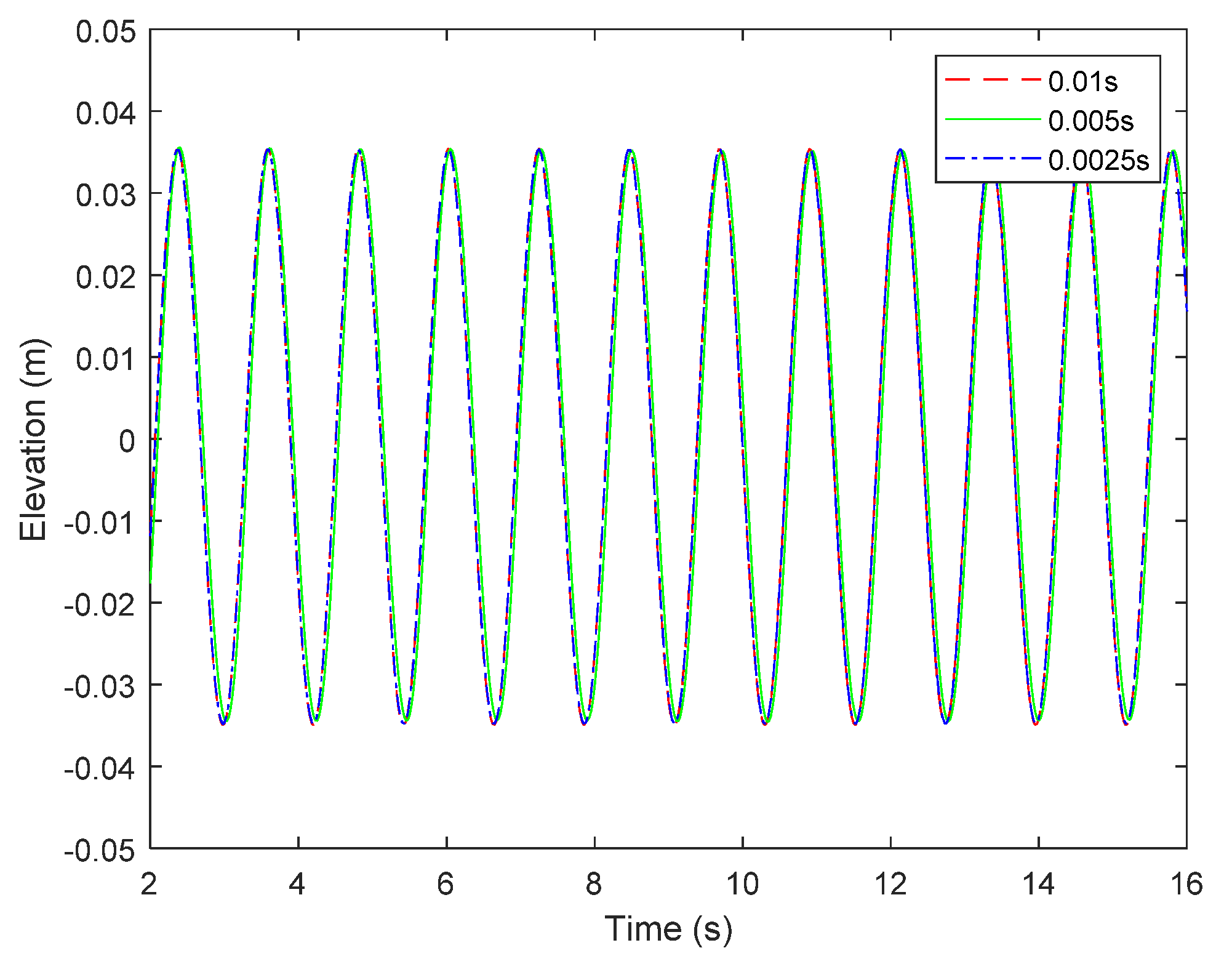
3.1. Numerical Wave Tank
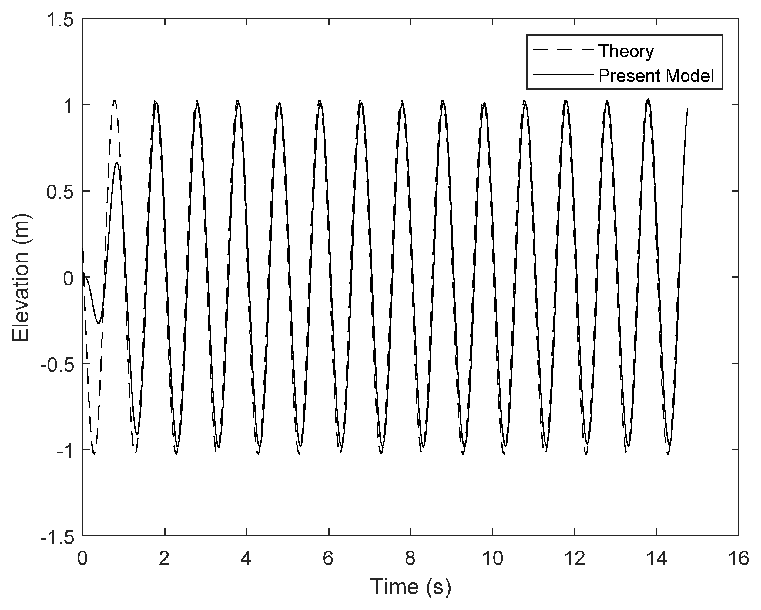
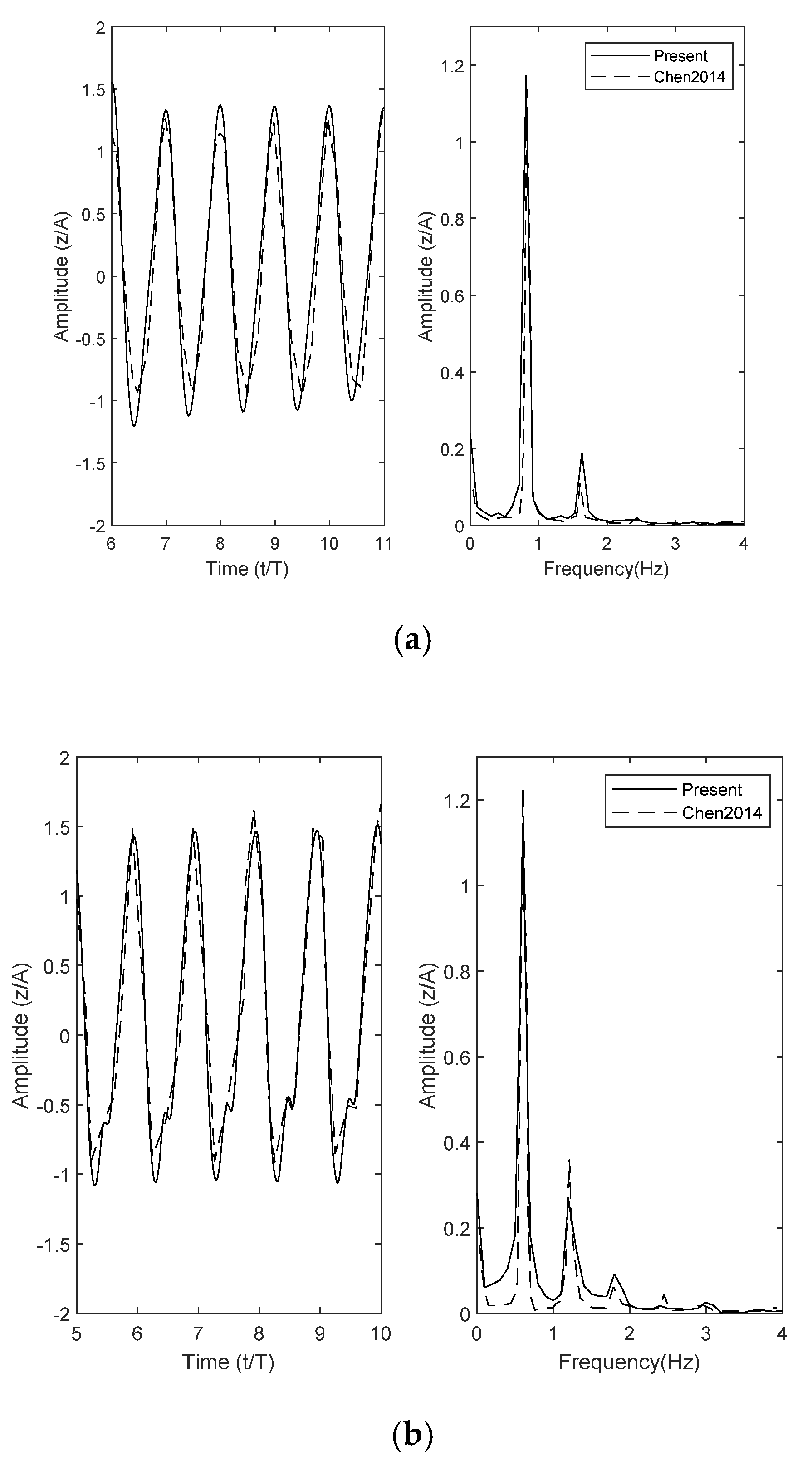
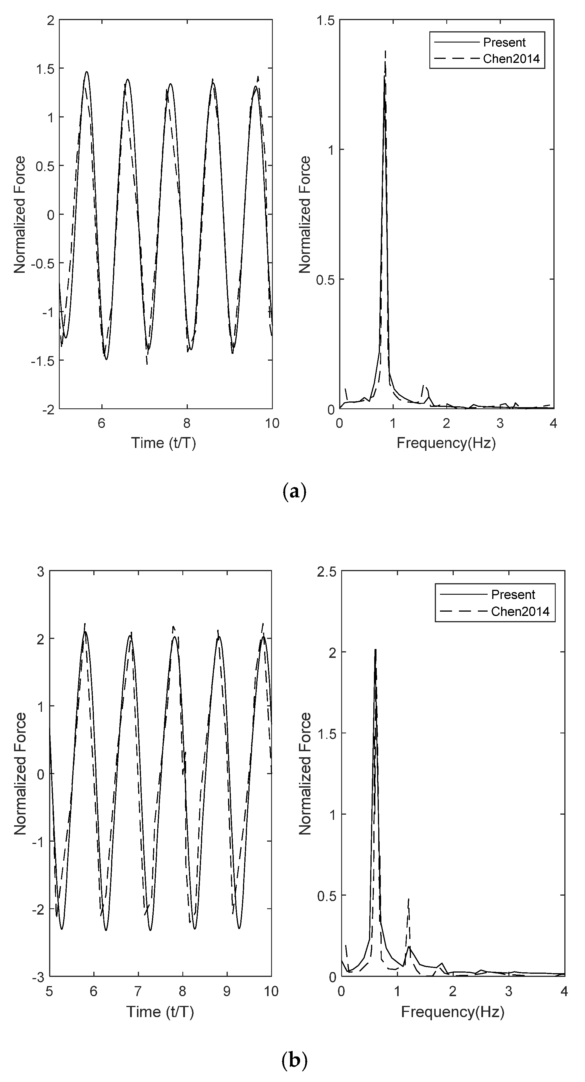
3.2. Comparison with the Published Data
4. Numerical Results
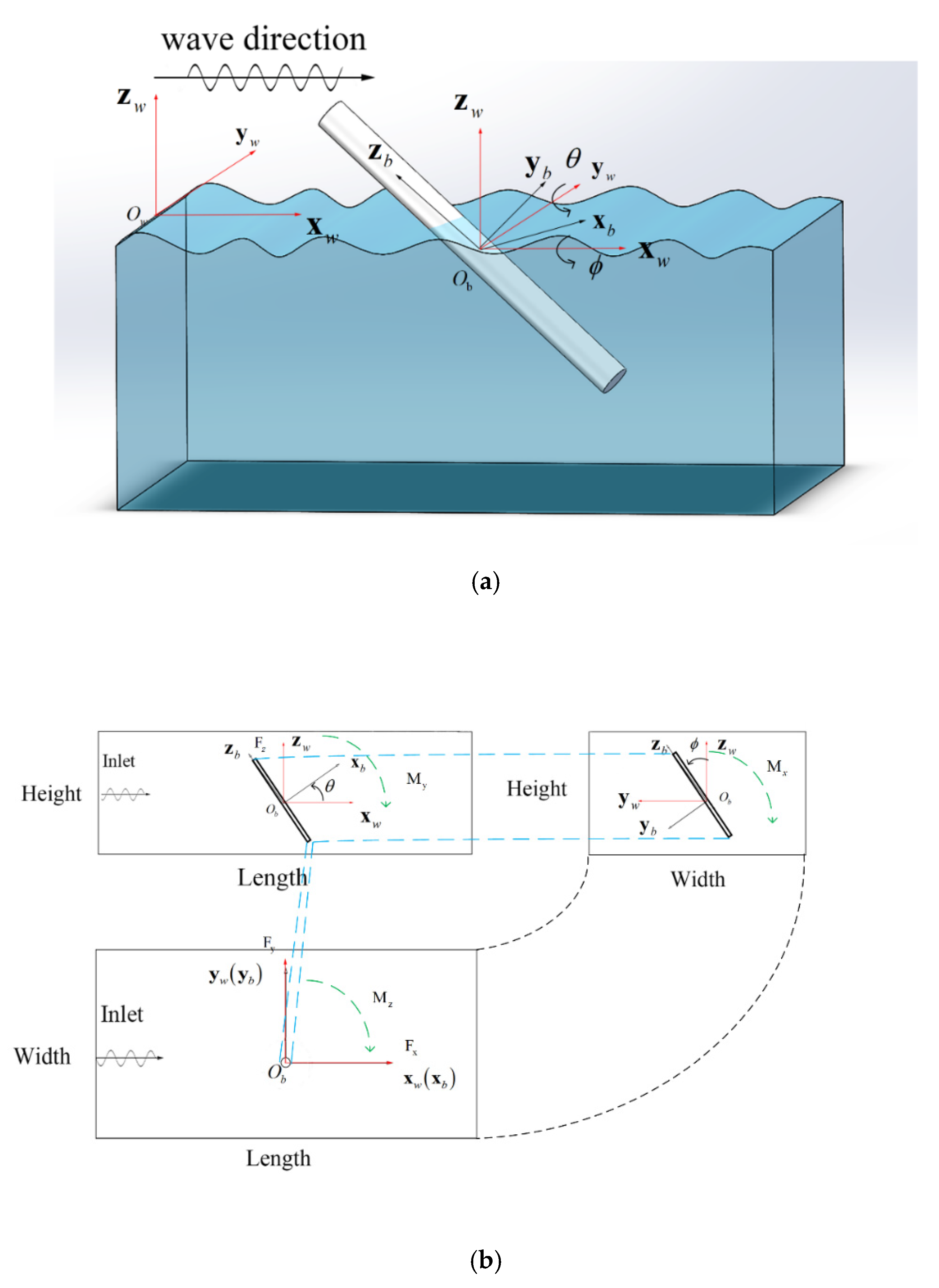
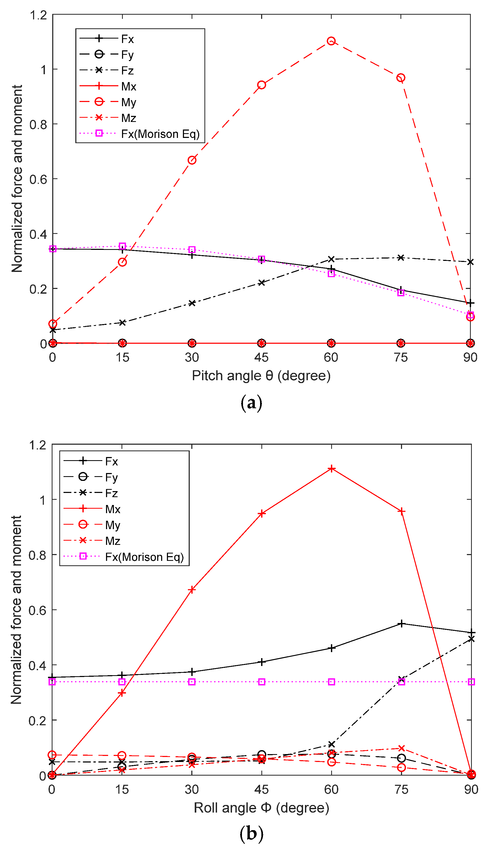
4.1. Case 1: A Cylinder Payload Fixed Suspending in the 3D NWT
- 1.
- Pitch angle , roll angle .
- 2.
- Roll angle , pitch angle .
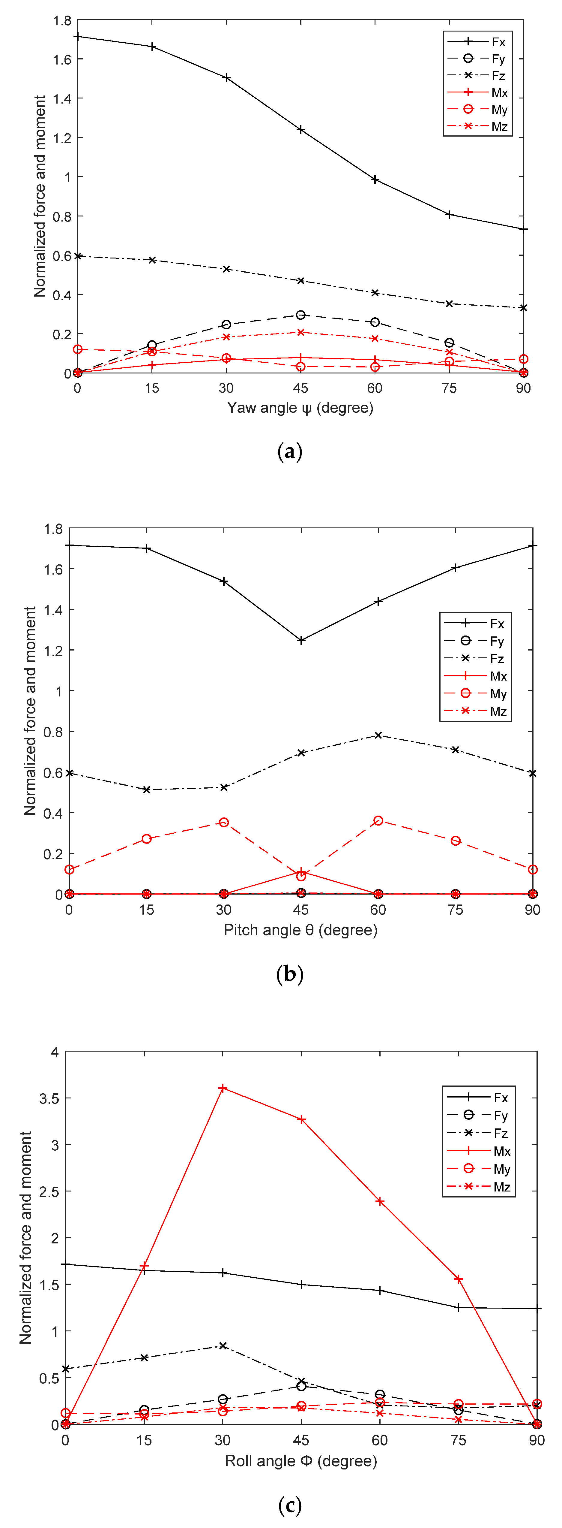
4.2. Case 2: A Cuboid Payload Fixed Suspending in the 3D NWT
- 1.
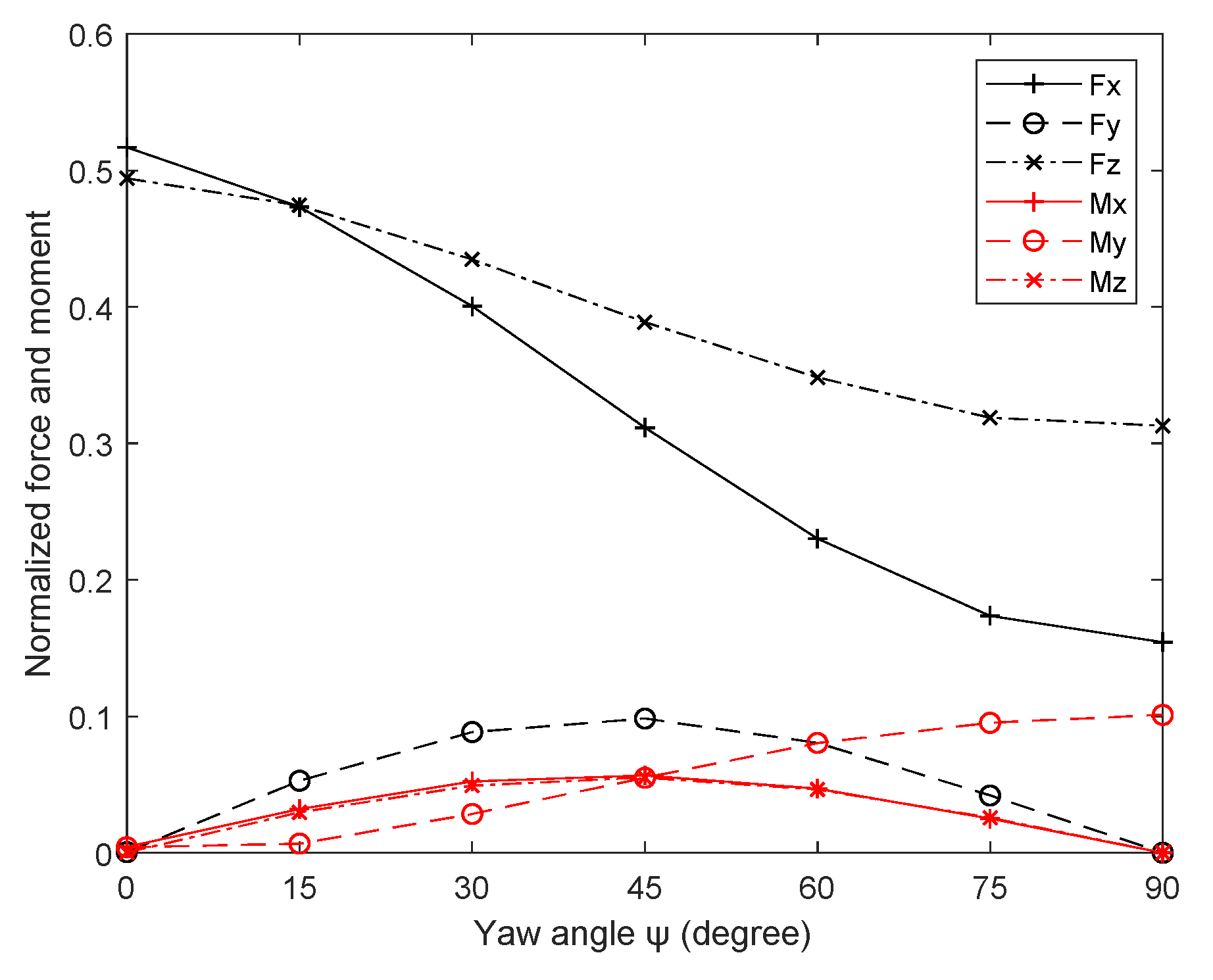
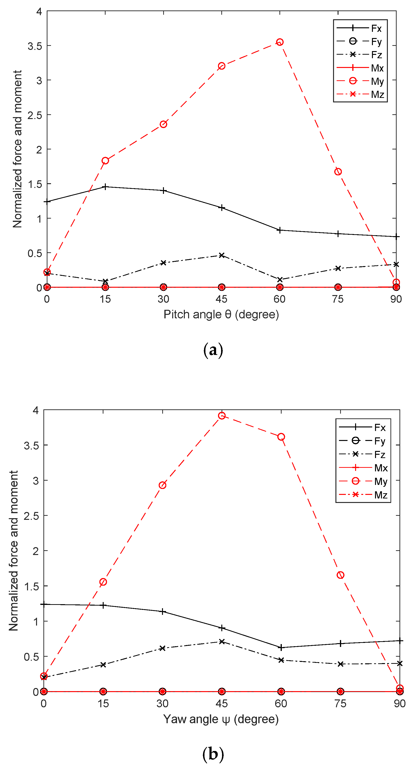
- Yaw angle , pitch and roll angle , .
- 2.
- Pitch angle , yaw and roll angle , .
- 3.
- Roll angle , pitch, yaw angle , .
- 4.
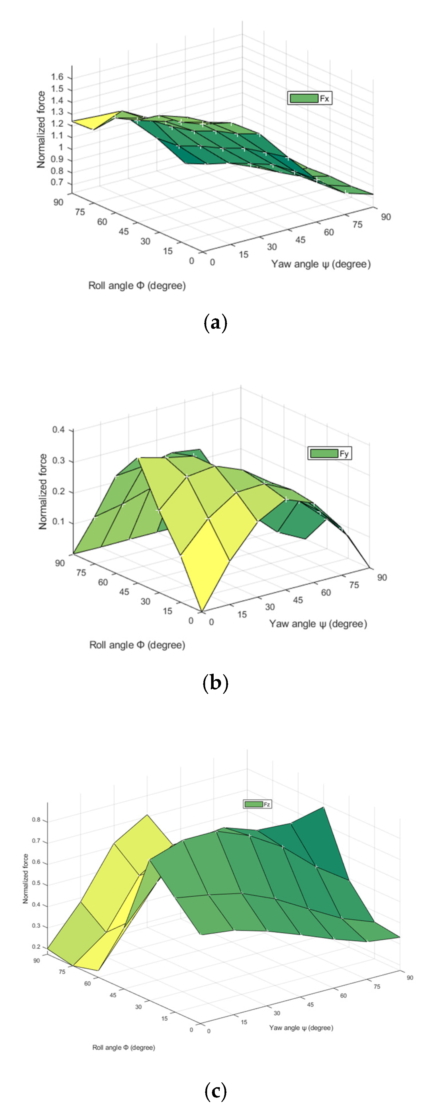
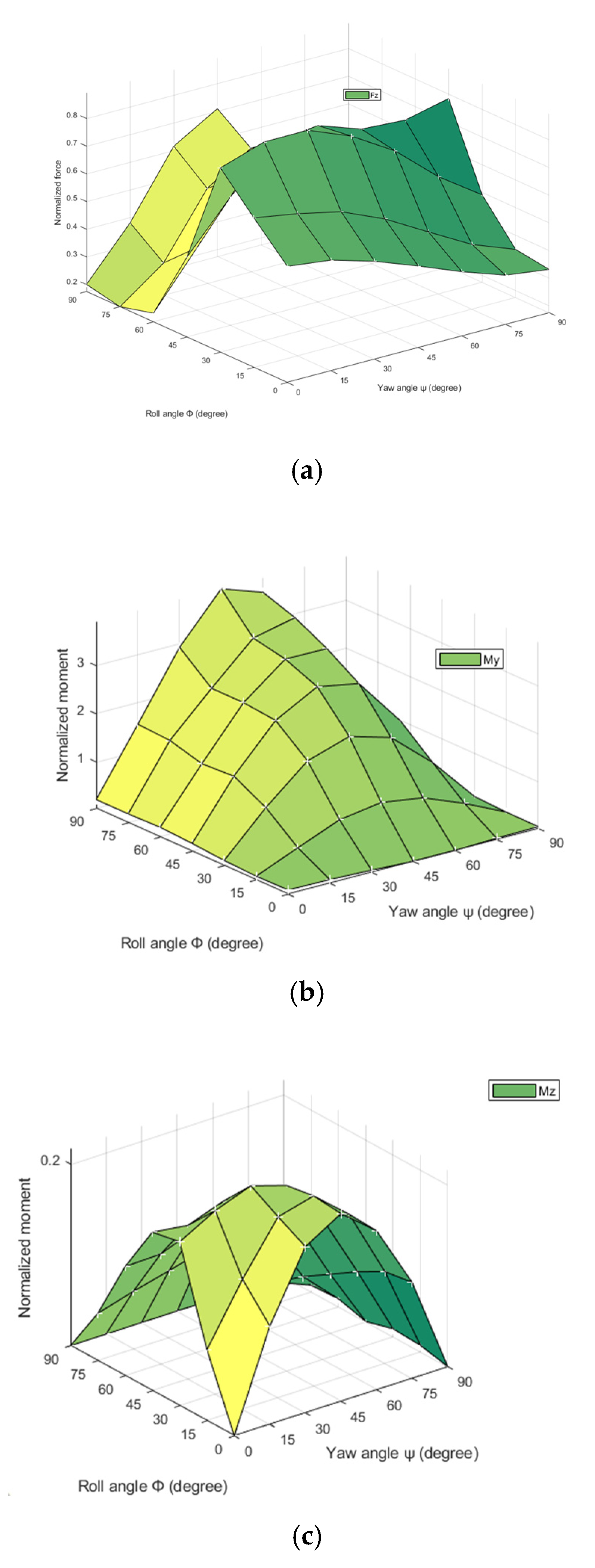
- Yaw and roll concurrently change from to , pitch .
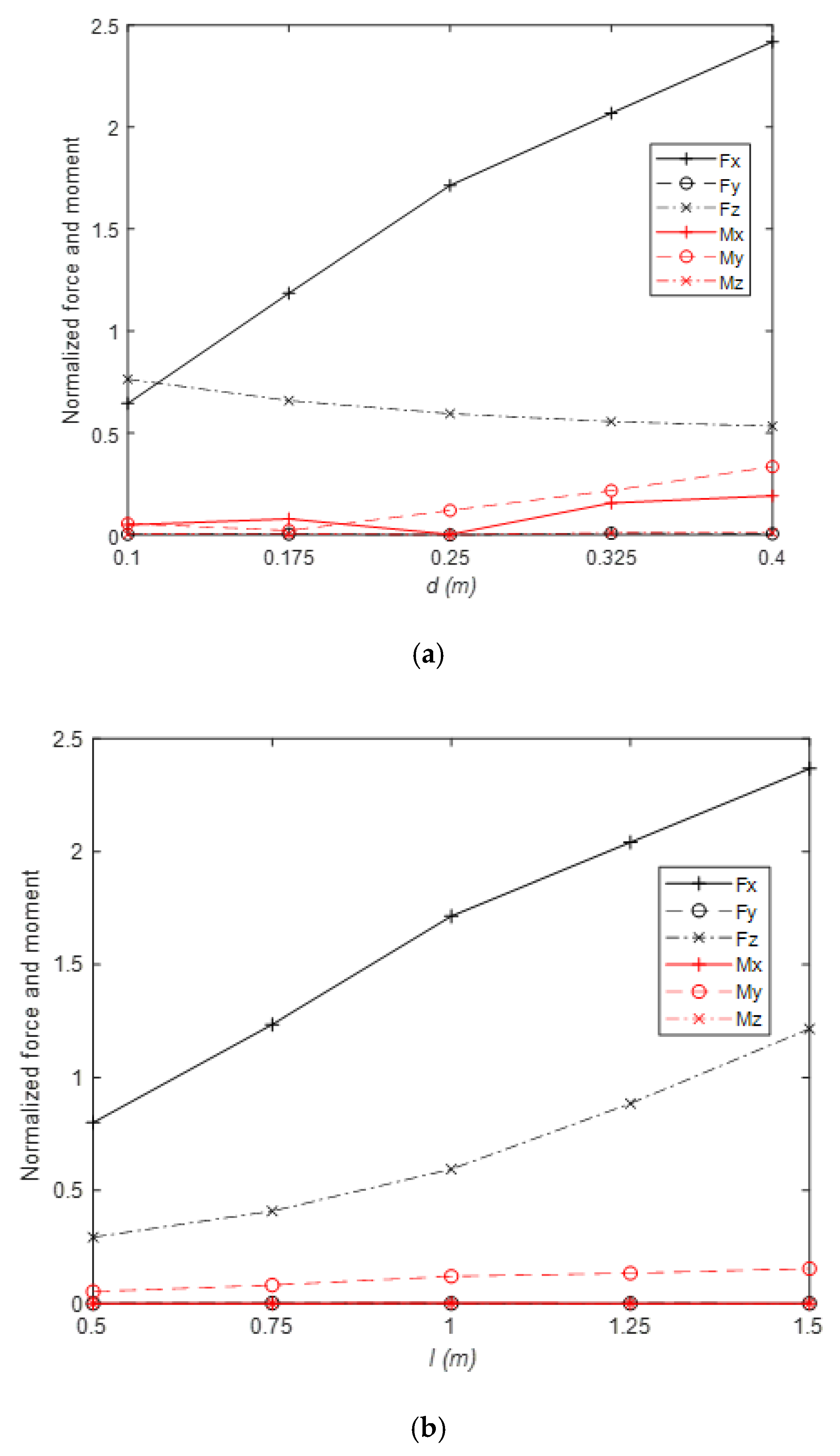
4.3. Parameter Studies
- 1.
- Cuboid’s size effects on forces and moments
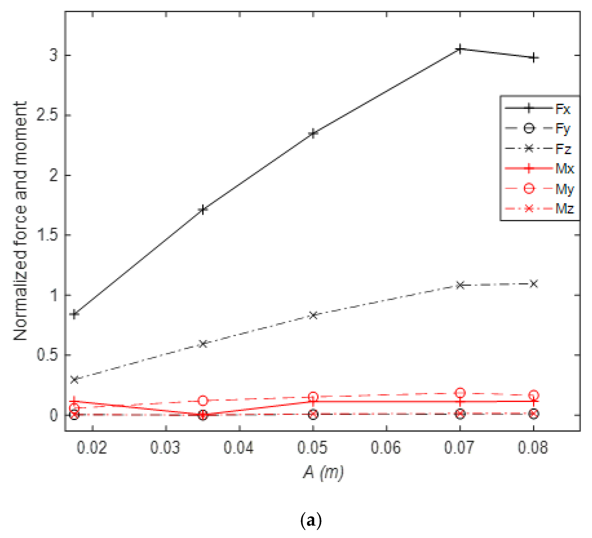
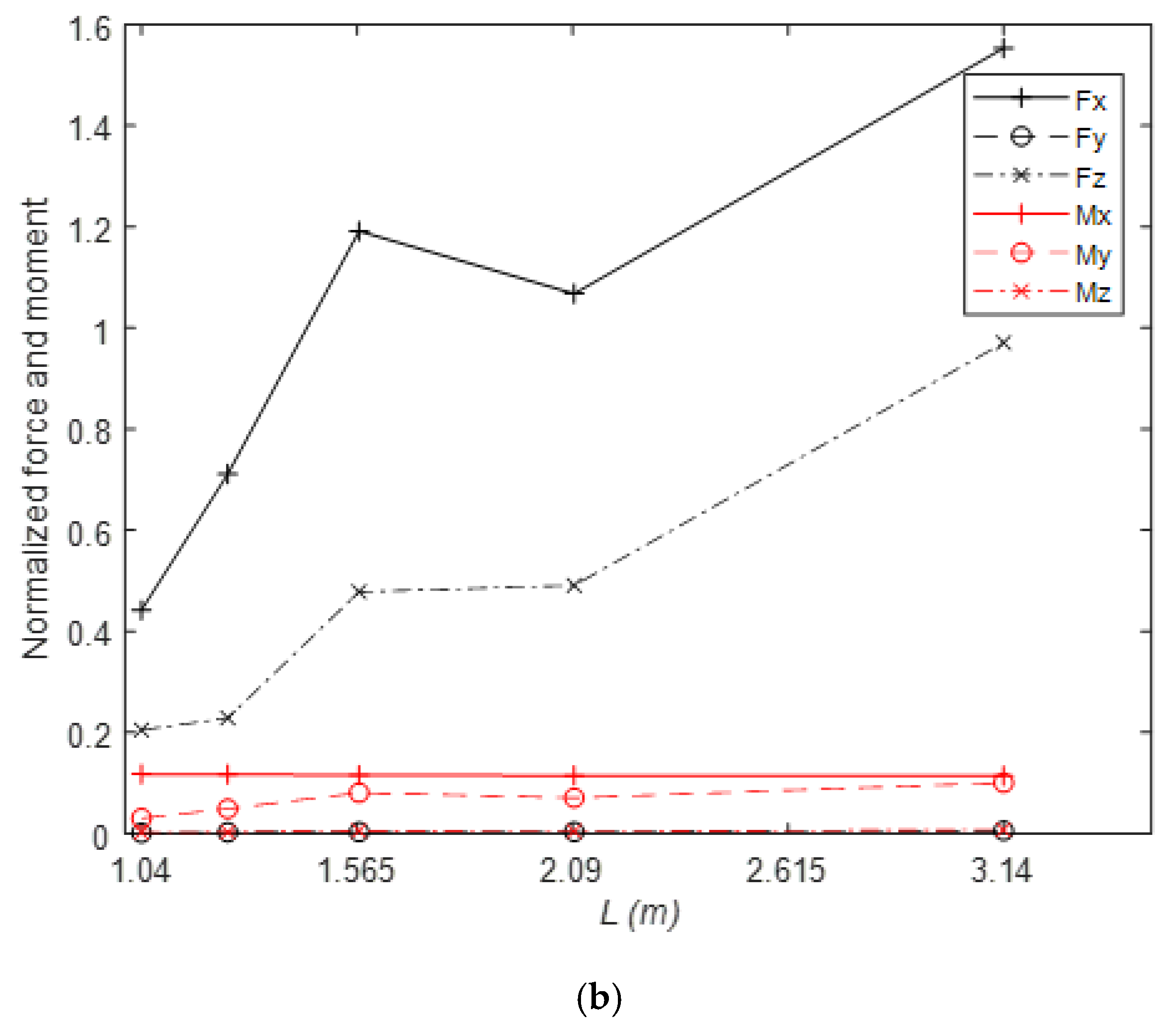
- 2.
- Wave’s parameters effects on forces and moments
5. Conclusions
Author Contributions
Funding
Conflicts of Interest
References
- DNV. Modelling and Analysis of Marine Operations; DNV Offshore Standards: Hovik, Norway, 2011. [Google Scholar]
- Chau, F.; Taylor, R.E. Second-order wave diffraction by a vertical cylinder. J. Fluid Mech. 1992, 240, 571–599. [Google Scholar] [CrossRef]
- Hunt, J.; Baddour, R. The diffraction of nonlinear progressive waves by a vertical cylinder. Q. J. Mech. Appl. Math. 1981, 34, 69–87. [Google Scholar] [CrossRef]
- Bai, W.; Taylor, R.E. Numerical simulation of fully nonlinear regular and focused wave diffraction around a vertical cylinder using domain decomposition. Appl. Ocean Res. 2007, 29, 55–71. [Google Scholar] [CrossRef]
- Del Jesus, M.; Lara, J.L.; Losada, I.J. Three-dimensional interaction of waves and porous coastal structures: Part I: Numerical model formulation. Coast. Eng. 2012, 64, 57–72. [Google Scholar] [CrossRef]
- Lara, J.L.; del Jesus, M.; Losada, I.J. Three-dimensional interaction of waves and porous coastal structures: Part II: Experimental validation. Coast. Eng. 2012, 64, 26–46. [Google Scholar] [CrossRef]
- Lin, P. A multiple-layer σ-coordinate model for simulation of wave–structure interaction. Comput. Fluids 2006, 35, 147–167. [Google Scholar] [CrossRef]
- Kang, A.; Lin, P.; Lee, Y.J.; Zhu, B. Numerical simulation of wave interaction with vertical circular cylinders of different submergences using immersed boundary method. Comput. Fluids 2015, 106, 41–53. [Google Scholar] [CrossRef]
- Ren, B.; Wen, H.; Dong, P.; Wang, Y. Numerical simulation of wave interaction with porous structures using an improved smoothed particle hydrodynamic method. Coast. Eng. 2014, 88, 88–100. [Google Scholar] [CrossRef]
- Didier, E.; Martins, R.; Neves, M.G. Numerical and Experimental Modeling of Regular Wave Interacting with Composite Breakwater. Int. Soc. Offshore Polar Eng. 2013, 23, 9. [Google Scholar]
- Ji, Q.; Dong, S.; Luo, X.; Soares, C.G. Wave transformation over submerged breakwaters by the constrained interpolation profile method. Ocean Eng. 2017, 136, 294–303. [Google Scholar] [CrossRef]
- Wang, J.-H.; Zhao, W.-W.; Wan, D.-C. Development of naoe-FOAM-SJTU solver based on OpenFOAM for marine hydrodynamics. J. Hydrodyn. 2019, 31, 1–20. [Google Scholar] [CrossRef]
- Liu, Z.H.; Wan, D.C.; Hu, C.H. Numerical investigation of regular waves interaction with two fixed cylinders in tandem arrangement. In Proceedings of the 37th ASME International Conference on Ocean, Offshore and Arctic Engineering, Madrid, Spain, 17–22 June 2018; ASME: New York, NY, USA, 2018. [Google Scholar]
- Lara, J.; Higuera, P.; Maza, M.; del Jesus, M.; Losada, I.J.; Barajas, G. Forces induced on a vertical breakwater by incident oblique waves. In Proceedings of the 33rd Conference on Coastal Engineering, Santander, Spain, 1–6 July 2012; Coastal Engineering Proceedings: Santander, Spain, 2012. [Google Scholar]
- Higuera, P.; Lara, J.L.; Losada, I.J. Three-dimensional interaction of waves and porous coastal structures using OpenFOAM®. Part I: Formulation and validation. Coast. Eng. 2014, 83, 243–258. [Google Scholar] [CrossRef]
- Chen, L.; Zang, J.; Hillis, A.; Morgan, G.; Plummer, A. Numerical investigation of wave–structure interaction using OpenFOAM. Ocean Eng. 2014, 88, 91–109. [Google Scholar] [CrossRef]
- Teng, B.; Zhang, X.; Ning, D. Interaction of oblique waves with infinite number of perforated caissons. Ocean Eng. 2004, 31, 615–632. [Google Scholar] [CrossRef]
- Fang, Q.H.; Hong, R.C.; Guo, A.X.; Stansby, P.K.; Li, H. Analysis of hydrodynamic forces acting on submerged decks of coastal bridges under oblique wave action based on potential flow theory. Ocean Eng. 2018, 169, 242–252. [Google Scholar] [CrossRef]
- Zheng, Y.-H.; Shen, Y.-M.; Ng, C.-O. Effective boundary element method for the interaction of oblique waves with long prismatic structures in water of finite depth. Ocean Eng. 2008, 35, 494–502. [Google Scholar] [CrossRef]
- Abul-Azm, A.; Gesraha, M. Approximation to the hydrodynamics of floating pontoons under oblique waves. Ocean Eng. 2000, 27, 365–384. [Google Scholar] [CrossRef]
- Gesraha, M.R. Analysis of Π shaped floating breakwater in oblique waves: I. Impervious rigid wave boards. Appl. Ocean Res. 2006, 28, 327–338. [Google Scholar] [CrossRef]
- Zheng, Y.; Liu, P.; Shen, Y.; Wu, B.; Sheng, S. On the radiation and diffraction of linear water waves by an infinitely long rectangular structure submerged in oblique seas. Ocean Eng. 2007, 34, 436–450. [Google Scholar] [CrossRef]
- Zheng, Y.; Shen, Y.; You, Y.; Wu, B.; Jie, D. Wave radiation by a floating rectangular structure in oblique seas. Ocean Eng. 2006, 33, 59–81. [Google Scholar] [CrossRef]
- Song, H.; Tao, L. Wave Interaction with an Infinite Long Horizontal Elliptical Cylinder. In Proceedings of the 30th International Conference on Ocean, Offshore and Arctic Engineering, Rotterdam, The Netherlands, 19–24 June 2011; ASME: New York, NY, USA, 2011; pp. 589–597. [Google Scholar]
- Weller, H.G.; Tabor, G.; Jasak, H.; Fureby, C. A tensorial approach to computational continuum mechanics using object-oriented techniques. Comput. Phys. 1998, 12, 620–631. [Google Scholar] [CrossRef]
- Jacobsen, N.G.; Fuhrman, D.R.; Fredsøe, J. A wave generation toolbox for the open-source CFD library: OpenFoam®. Int. J. Numer. Methods Fluids 2012, 70, 1073–1088. [Google Scholar] [CrossRef]
- Morison, J.; Johnson, J.; Schaaf, S. The force exerted by surface waves on piles. J. Pet. Technol. 1950, 2, 149–154. [Google Scholar] [CrossRef]


| Regular Wave | A(m) | T(s) | kh | kA |
|---|---|---|---|---|
| R1 | 0.035 | 1.22 | 1.39 | 0.1 |
| R2 | 0.06 | 1.63 | 0.86 | 0.1 |
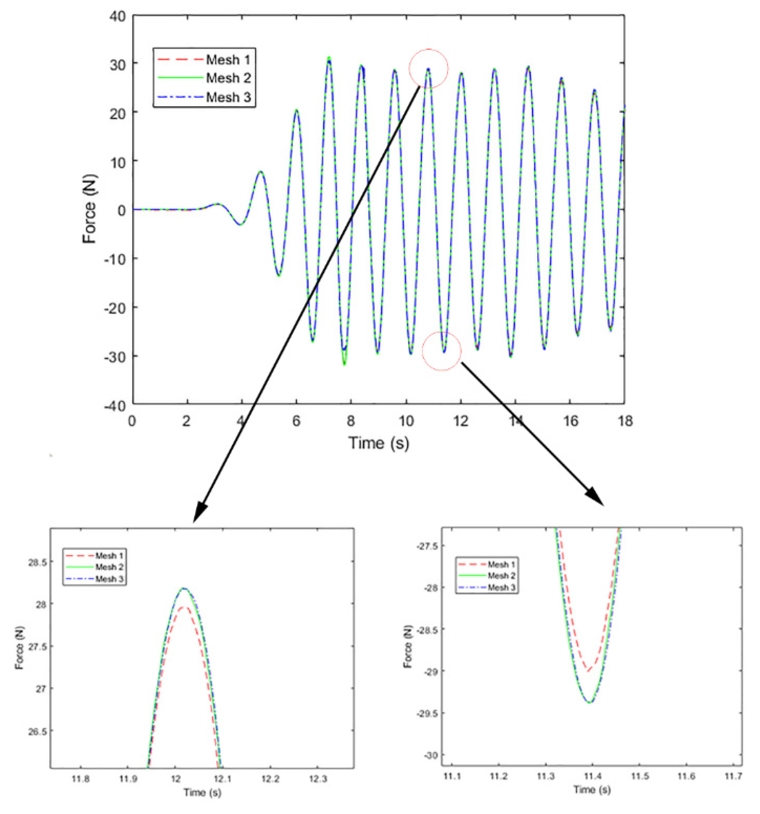
| Mesh Scheme | ∆x = ∆y | ∆z | Cell Number (Million) | Cores | Run Time (h) |
|---|---|---|---|---|---|
| 1 | L/88 | H/15 | 2.04 | 24 | 3.15 |
| 2 | L/110 | H/30 | 5.88 | 24 | 12.54 |
| 3 | L/132 | H/45 | 16.88 | 24 | 55.4 |
© 2020 by the authors. Licensee MDPI, Basel, Switzerland. This article is an open access article distributed under the terms and conditions of the Creative Commons Attribution (CC BY) license (http://creativecommons.org/licenses/by/4.0/).
Share and Cite
Yan, M.; Ma, X.; Bai, W.; Lin, Z.; Li, Y. Numerical Simulation of Wave Interaction with Payloads of Different Postures Using OpenFOAM. J. Mar. Sci. Eng. 2020, 8, 433. https://doi.org/10.3390/jmse8060433
Yan M, Ma X, Bai W, Lin Z, Li Y. Numerical Simulation of Wave Interaction with Payloads of Different Postures Using OpenFOAM. Journal of Marine Science and Engineering. 2020; 8(6):433. https://doi.org/10.3390/jmse8060433
Chicago/Turabian StyleYan, Mingwei, Xin Ma, Wei Bai, Zaibin Lin, and Yibin Li. 2020. "Numerical Simulation of Wave Interaction with Payloads of Different Postures Using OpenFOAM" Journal of Marine Science and Engineering 8, no. 6: 433. https://doi.org/10.3390/jmse8060433
APA StyleYan, M., Ma, X., Bai, W., Lin, Z., & Li, Y. (2020). Numerical Simulation of Wave Interaction with Payloads of Different Postures Using OpenFOAM. Journal of Marine Science and Engineering, 8(6), 433. https://doi.org/10.3390/jmse8060433