1. Introduction
The work in this paper proposes guidance and control algorithms for an autonomous underwater vehicle (AUV) diving together with a diver. These algorithms are the first step towards proving a larger hypothesis that divers and AUVs have a set of complementary traits such that a synergistic diver–robot approach offers a solution for current diving challenges in safety, navigation and communication. This diver–robot collaboration, researched under the EU FP7 “CADDY
1—Cognitive Autonomous Diving Buddy” project [
1], entails providing services such as continuous mission monitoring for increasing diving safety, navigation aiding towards points of interest and relaying underwater communication between divers and surface. To better motivate this collaboration, consider that the underwater environment is not a natural habitat for humans. Divers are dependent on technical equipment for life support and have limited communication with the surface. Changing currents, low visibility and lack of pronounced environmental references complicate underwater navigation. Therefore, these issues of safety, navigation and communication are readily identified as main topics to be addressed.
From the safety perspective, SCUBA diving activities, whether they are recreational, scientific or technical, are classified as high–risk due to (i) unpredictable, dangerous and unfamiliar environment under influence of external disturbances, (ii) dependency on technical equipment that ensures life support, and (iii) health consequences diving can have on a diver. Statistics show that 40% of the fatalities take place during a period of buddy separation and 14% involved declared solo dives, leading to more than 50% of accidents happening while the divers were alone [
2]. This stresses the importance of diving in pairs to have immediate assistance, the second diver is often referred to as the diving buddy. During solo dives or buddy separation, having an AUV (designed to always follow the diver) as a drop-in diving buddy increases safety. At minimum the vehicle provides a stable reference in reduced visibility, provides the diver with his exact position, can carry an extra air tank for safety, etc. With cognitive capabilities the vehicle can reason about the diver’s state and current mission and react accordingly to ensure safety.
In addition to safety, diving activities are significantly exacerbated by reduced navigation and communication capabilities. Classical techniques for underwater navigation, such as referencing according to the sun, compass, underwater features, are imprecise, tedious and require significant amount of concentration and experience. Current acoustic localization solutions enable positioning relative to a surface or bottom station. However, they exhibit performance deterioration with increased range due to acoustic multi-path effects [
3]. For the same reason, communication between a diver and the surface is limited thus compromising surface monitoring of the dive. On the other hand, the use of autonomous surface vehicle (ASV), remotely operated underwater vehicles (ROVs) and autonomous underwater vehicles (AUVs) has enabled underwater exploration at a faster pace by providing remote underwater presence. ASVs can be used to track underwater systems thus reducing multi-path effects in acoustic localization and communication [
4]. Meanwhile, AUVs are equipped with sensors providing good underwater navigation, but they often lack dexterity and/or higher cognitive capabilities to accomplish advanced tasks better suited for divers. AUV sensors can be mounted in hand-held diving units thereby providing the diver with a more accurate position. However, carrying the units occupies both hands and the extra effort contributes to more oxygen usage and dissolved nitrogen in the blood. Additionally, most units require the diver to level the unit, adhere to minimum altitude and other limits to ensure quality of positioning. Having an AUV diving buddy removes the extra effort from the diver while still providing accurate positioning. Finally, from a communication perspective, during the dive there is an increased chance of occluding the acoustic transducers and losing communication with the surface as distance increases. Having the AUV nearby to relay the communication increases the chance of receiving the message even when the transducer on the diver is occluded and the signal attenuated.
The previous arguments point towards the benefits of using a standalone AUV platform for diver–robot collaboration instead of overloading the diver with additional equipment. Furthermore, to ensure such capabilities the guidance and control algorithms presented in this paper are a valuable foundation together with other related works reviewed in the next sub-section.
1.1. Related Work
Among the first autonomous robots for diver–robot interaction is the AquaRobot [
5] where the on-board camera image is analysed to recognize diver motion and subsequently used for underwater diver tracking [
6]. The problem of AUV manoeuvring in presence of divers is investigated in [
7]. In an environment with potentially multiple divers, the AUV uses reactive and deliberative control strategies to achieve manoeuvring without collisions. Diver following in a simulated environment, with sonar based diver detection, was researched in [
8]. Same authors have shown, on real-world results, the feasibility of diver detection and tracking using sonar images [
9]. Guidance of people through the environment has been mostly studied in land robotics applications. Museum tour-guide robots are among the first to tackle the problem [
10]. They move in complex environments and need to handle cooperative and uncooperative agents, but the solution are not easily transferred to underwater situations. Sadly, when it comes to underwater robots it is hard to find guide or navigation aiding robot examples. Even examples of diver following are scarce [
11]. Therefore, the research has to be compared with land applications which is problematic. Guide and following robots in land applications allow for more freedom of movement, i.e., do not necessary maintain close formation, which is wanted in a diving buddy.
When shifting the focus away from diver–robot scenarios, many guidance and control algorithms for AUV are available in the literature. The proposed controllers rely on a nonlinear path following design referred in the literature as the virtual target (VT) approach. Such a design operates with a virtual point onto which the vehicle converges [
12]. This design pattern emphasizes spatial localization, i.e., kinematics, over kinetics [
13]. Previous works dealt mostly with underactuated vehicles which are more common and more challenging to control. Therefore, this approach can also be applied to hover capable AUVs. Applications for underactuated underwater vehicles are found in [
14,
15,
16] for both 2D and 3D paths. In [
15] limits on the initial AUV position, present in [
12,
16], are avoided by explicit control of the virtual target speed. A general control law for 2D and 3D paths is presented in [
13] and extended to dynamics of a fully-actuated vessel in [
17].
1.2. Contribution
The related work section shows that diver–robot collaboration research is a relatively small area with relatively few groups compared to land-based human-robot interaction research. Related works deal more with the diver tracking problems than with diver guidance.
In this paper the aim is to control the vehicle so these functions (tracking, guidance, interaction) are achievable simultaneously without explicit switching between following, leading or positioning for gesture recognition. With this the main contribution can be defined as a set of control algorithms enabling diver relative manoeuvring of a fully-actuated AUV for purpose of continuous diver monitoring and navigation aiding without assuming the role of the leader in the diver–robot team.
1.3. Paper Layout
To better describe the problem and applied methods, a top-down approach is used. First, the CADDY project concept is described and the requirements stated, followed by the introduction of the used vehicle and sensors.
Section 4 models the diver–robot pair and derives the proposed control algorithms. Experiments with their interpretation are presented in
Section 5 and the paper is concluded with the discussion about benefits and limitations of the proposed control algorithms with envisioned future work.
2. Background
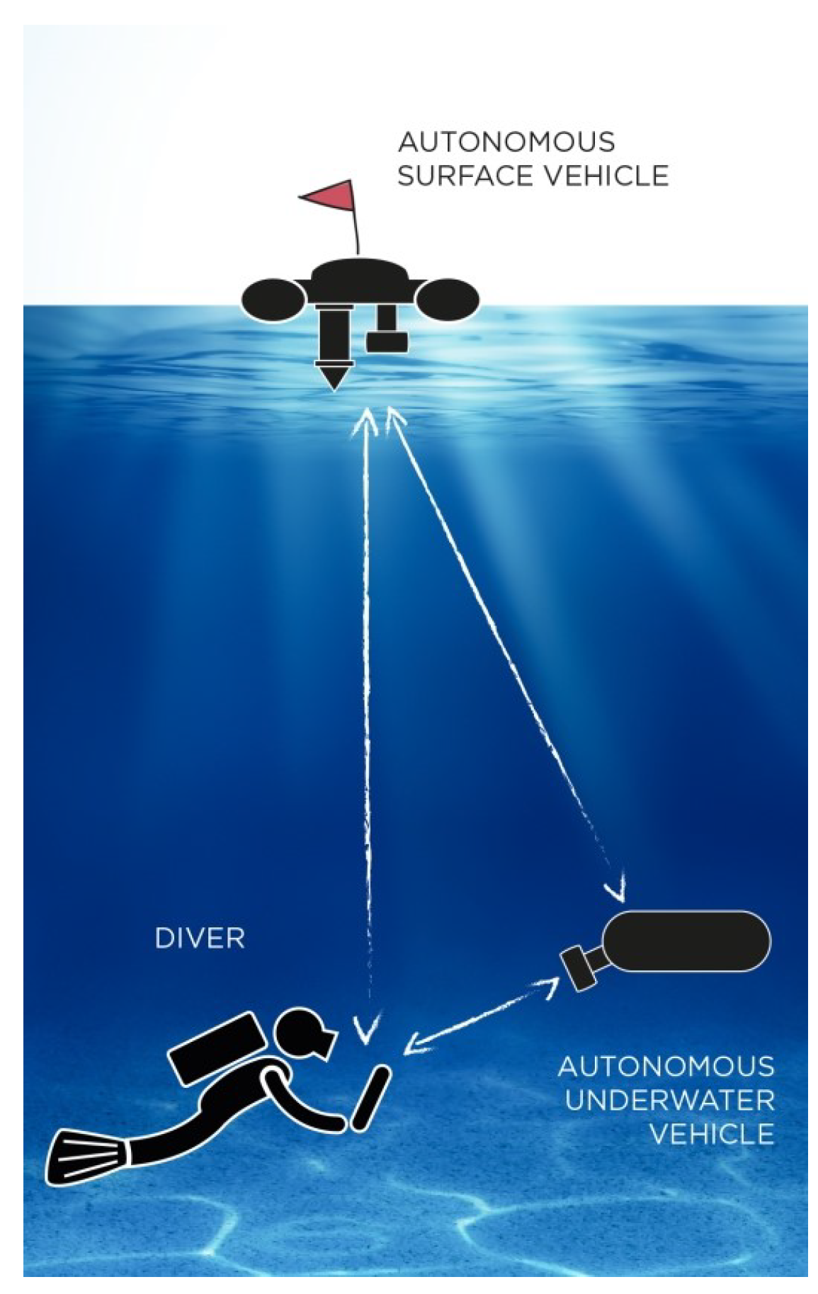
The CADDY project’s key goal was to enhance underwater human-robot cooperation and interaction through development of new systems for diver monitoring. The concept, shown in
Figure 1, provides a symbiotic link between a diver and two companion robots. The autonomous surface vehicle (ASV) communicates with the diver and the AUV thereby acting as a communication relay to the command centre. Simultaneously, it provides localization aiding for both underwater agents. The AUV, referred from here on as BUDDY (reference to a dive buddy), plays the role of an underwater robotic companion. Within the CADDY concept, BUDDY provides a threefold functionality to divers:
- (F1)
Observe functionality—moves with the diver and monitors the mission from the best viewpoint;
- (F2)
Guide functionality—provides a reference for the diver to aid navigation towards a target;
- (F3)
Slave functionality—set of actions (e.g., bring tool, take photo) commanded by diving gestures.
The Observe functionality ensures that the whole dive is better monitored and the diver’s behavior can be analysed to detect any divergence from the baseline. The Guide functionality has different navigation aiding options. Use of BUDDY to point the direction towards the target is demonstrated in the paper. Other options are discussed in
Section 6. This paper will focus on the results obtained toward the Observe and Guide functionalities with Slave functionality controllers ignored for sake of brevity.
The BUDDY AUV was developed specifically for the purpose of exploring human-robot interaction in the underwater environment [
19]. It is fully-actuated in the horizontal plane and can independently control heave and pitch degree of freedoms (DoFs). The vehicle, shown in
Figure 2, is equipped with a wide range of sensors required to implement envisioned functionalities. BUDDY is
long,
wide,
high and weighs about 70
. The basic payload includes:
u-blox Neo 5M global navigation satellite system (GNSS);
Microstrain GX3 inertial measurement unit (IMU);
LinkQuest Navquest 600M doppler velocity logger (DVL);
Ubiquiti wireless communication;
48 V lithium battery;
VideoRay Pro4 brushless thrusters.
Additional components include exteroceptive sensors such as stereo and mono camera, forward looking multibeam imaging sonar (FLS), an acoustic positioning system and a tablet mounted in the underwater housing for visual feedback. More details about other components are available in [
19].
3. Requirements
Based on the Observer and Guide functionalities described earlier, the control problem can be defined by three requirements:
- R1:
Distance keeping BUDDY should be close enough to enable monitoring via sonar/camera but without compromising diver safety or personal space.
- R2:
Orientation BUDDY should be always oriented towards the diver to ensure the diver is in the field of view (FoV) of sensors at all times.
- R3:
Relative position BUDDY should be able to position relatively in any point around the diver to be able to provide a navigation reference towards the target.
It is easy to relate
and
to the Observe function and
and
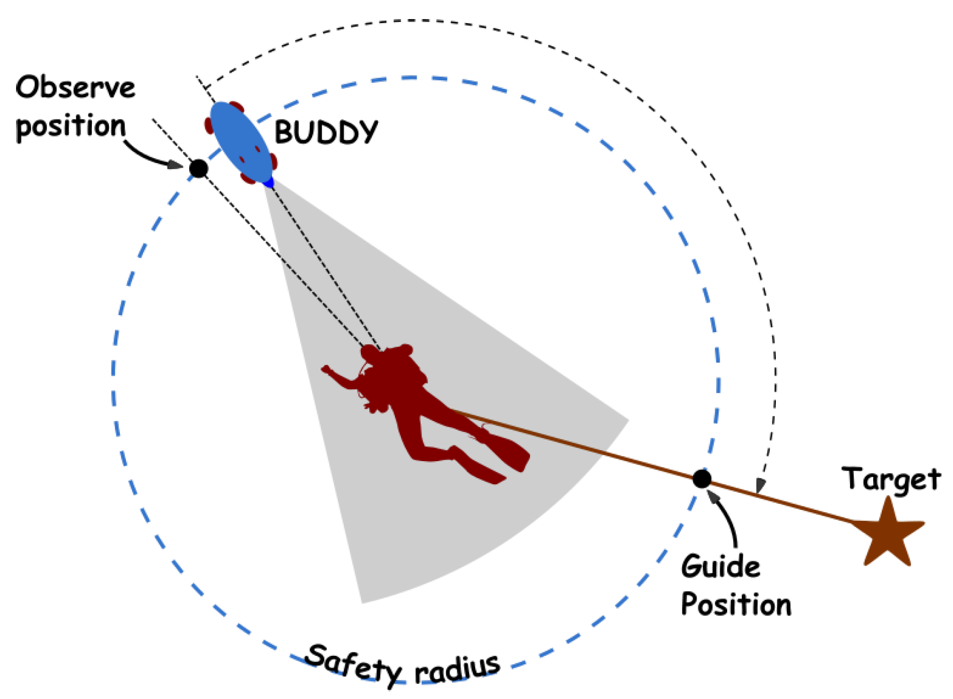
to the Guide function. The observe position, shown in
Figure 3, is maintained during Observe function with BUDDY looking at the diver. During Guide, the vehicle is positioned as a pointer reference towards the desired target while at the same time fulfilling
. Note that from a design perspective, these requirements enforce BUDDY to be a fully actuated vehicle allowing separate position and orientation control.
Knowing the relative diver position is the main prerequisite for meeting –, while additionally needs knowledge about the AUV’s absolute position. The relative diver position is measured from (a) pressure sensors, (b) stereo-camera, (c) sonar and (d) ultra-short baseline acoustic positioning sensor (USBL).
Both the diver and BUDDY have pressure sensors for depth measurements. The diver’s depth is part of the communication payload. Therefore, relative diver depth can be calculated and is used to ensure that the diver and BUDDY share the same horizontal plane.
The stereo-camera mounted on BUDDY is the Bumblebee XB3 color stereo-camera. The stereo camera point-cloud is used to extract diver’s relative distance, azimuth, elevation and a general diver orientation vector, i.e., the centre of the diver’s FoV. Low visibility underwater hinders use of camera for ranges larger than 3 . More precisely, the stereo camera point cloud deteriorates fast with increased distance even in visibility conditions where the diver can see up to 10 . Therefore, the diver orientation vector can not be estimated reliably after 3 . The azimuth and elevation are available for longer distance albeit with lower measurement confidence.
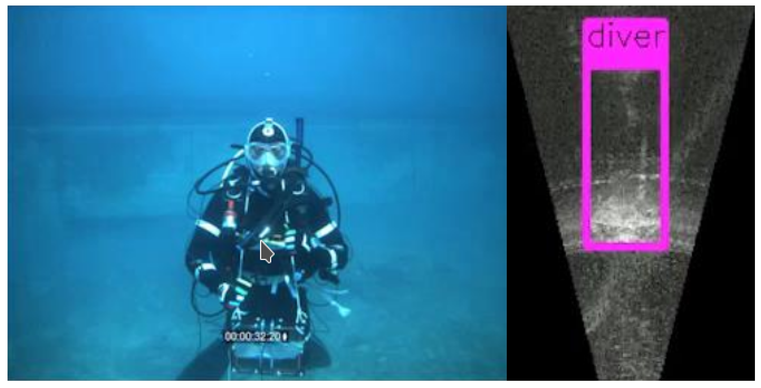
The forward looking imaging multibeam sonar mounted on BUDDY is the Sound-metrics ARIS 3000 FLS. The sonar is usable in all visibility conditions and can be used from 2
to 15
. This makes it the main sensor for larger ranges, especially during diver (re-)acquisition. For a better comparison with a camera sensor,
Figure 4 shows a comparison of the same scene taken by a camera and sonar sensor. It can be seen that the sonar provides a 2D depth like image rather than a typical camera view. Therefore, the sonar provides the diver’s relative distance and azimuth, but can not provide relative elevation.
The USBL sensor mounted on BUDDY is the Blueprint SeaTrac X150 USBL. The sensor operates on ranges 1
to more than 500
. It measures relative diver’s range, azimuth and elevation. These measurements are of low rate and precision when compared with the camera and the sonar. However, these are fallback measurements in case the diver is lost from both camera and sonar view. The precision of SeaTrac X150 USBL is enough to allow diver requisition as was shown in [
20]. As noted previously, absolute positioning is a prerequisite for
. The USBL sensor is used to provide these measurements by measuring relative BUDDY position to an ASV with known absolute position.
Independent on available measurements, the general assumption for the control algorithms is that a robust estimates of relative diver position and orientation vector are available. For BUDDY, this is provided by the sensor fusion described in [
20]. Note that once the diver position relative to BUDDY is known, the absolute diver position can be easily calculated from BUDDY’s position. This absolute diver position is transmitted as part of the acoustic payloads during simultaneous localization and communication.
4. Diver Relative Maneuvering Controller
Three controller requirements were identified previously based on the selected Observe and Guide functionalities. During the design phase it was decided that a single controller should handle both functionalities and allow for multiple high-level goals to configure set-points (inputs) of the controller. Following assumptions are necessary for the controller derivation:
- (A1)
Estimates of the diver position and heading are continuously available;
- (A2)
Surge, sway, heave and yaw are actuated DoFs;
- (A3)
Roll and pitch stable around .
Measurements of diver position and heading are inherently intermittent, delayed and of different precision depending on sensor type, i.e., camera, sonar or USBL. Therefore, to isolate the control derivation from different source
should hold so that the control state is continuously available. Satisfying
requires control of position and orientation which is unfeasible with under-actuated vehicles, hence,
is an assumption about the required vehicle type. The vehicle should also control heave directly to allow maintaining depth while satisfying
. Finally,
ensures that an uncoupled vehicle model can be used for the controller derivation. Note that, in case of BUDDY, roll and pitch stability is inherent to the vehicle design. Pitch can still be controlled, but for clarity of derivation it is assumed close to
and ignored in following transformations. From a practical standpoint, pitch angles, even when controlled, are preferred small to avoid affecting precision of acoustic navigation sensors such as DVL. With pitch and roll around
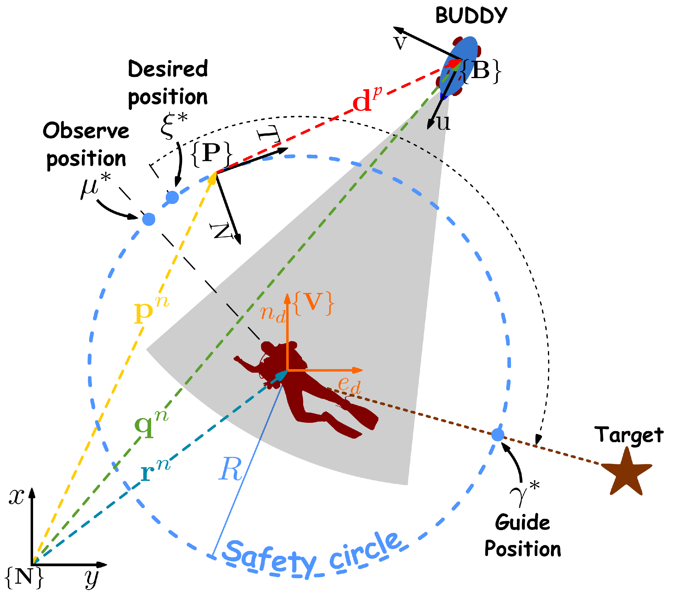
, the sensors are always looking along the horizontal plane. This is not an issue, since the proposed controller maintains the vehicle depth equal to that of the diver. Starting from these notes and assumptions the diver–robot pair can be modeled. During modeling and controller derivation, the surface vehicle is ignored as it operates independently from the diver–robot pair. The corresponding notation is based on
Figure 5.
Let
be the navigation frame, i.e., the local tangent plane, in which the vehicle position
, diver position
and the path frame
origin
are defined. The path frame
, often referred to as Frenet-Serret frame, is bound to the continuously parameterized path where
is the parameterization variable. The path frame axes are defined by the curve’s tangent
, normal
and binormal
axes. The Frenet-Serret frame origin is defined as the exact projection point of the vehicle onto the desired path [
13]. However, the path frame in this derivation is satisfying the former definition, irrespective of its origin.
Starting with kinematics, the vehicle location in
can be written as
, where
and
is the transformation matrix from
to
. Variables
s,
e and
h denote the Cartesian coordinates of the vehicle in
along the
,
and
axes, respectively. While
s and
e are horizontal coordinates, the coordinate
h represents the relative depth of the vehicle with respect to
. Using these definitions results with the following kinematic equation
where
represents linear velocities in the body frame and
is the resulting skew-symmetric matrix from derivative of
. The complete equation requires calculation of
velocity in
. The frame relation can be written as
where
. The transformation between diver fixed navigation frame
and
is by definition identity and
. Differentiating gives the
origin rate (velocity) along the path as
where
is a skew-symmetric matrix. The origin location in
, denoted as
, is
thereby making the last term disappear. However, the frame still moves tangentially along the path with speed
, where
. It is advantageous to rewrite
in term of the path position error
, since the controller derivation will consider path stabilization rather than path following. Finally, the kinematic equation reduces to
With kinematics defined, kinetics can be reviewed. Detailed analysis of marine vehicle dynamics is provided in [
22]. From there it is known that the kinetics of an underwater vehicle can be described with simplified uncoupled dynamics as
where
,
are diagonal matrices. The virtual input
is specified for notation brevity and it includes vector of generalized forces
, environmental disturbances
, and gravitational and buoyancy forces influence
. Recall that
is positive definite and
is positive semi-definite, and that the uncoupled model is valid under assumption
.
4.1. Controller Design
Following the defined mathematical model the control algorithms can be designed to fulfill requirements
specified in
Section 2.
can now be specified with respect to Equation (
3) as achieving
which guarantees convergence to the defined circular path thus ensuring distance keeping. Since assumption
is in effect,
is addressed with a separate controller described in
Section 4.1.2. Finally,
can also be specified with respect to (
3) as achieving
with
.
4.1.1. Path Stabilization (R1 and R3)
Controllable inputs in the kinematic Equation (
3) are
and
. The
progression rate
along the path is a control input within the controller without any actual actuation. The AUV velocity
is controlled indirectly through the low-level velocity controller generating actuation commands. To achieve
and
, consider the Control Lyapunov Function (CLF)
with
is defined as
where
are control gain parameters. Note that
is a valid energy function since
and
. The CLF gradient is derived as
where
due to skew-symmetry of
. The first term can be made negative by selecting the desired velocity profile in Equation (
9), where
is positive definite. Selecting Equation (10) for
origin velocity along the path ensures the second term is made negative. Recall that
, therefore, the term
reduces to the tangential coordinate
s.
in Equation (10) is the third control gain of the controller. Applying the proposed control signals reduces the CLF gradient to
which is negative
. It follows that the kinematics with control inputs (9) and (10) is globally asymptotically stable (GAS).
The above discussion proposed the control law in Equations (9) and (10) which provides a stable closed loop control. To complete the derivation, a low-level control law
is needed which can track the desired velocity profile given with Equation (
9). Introducing the velocity tracking error
and rewriting Equations (
3) and (
4) in the error form yields
The expanded CLF can be selected as
, where
is a positive constant assuring unit correctness.
V is differentiated as
where
. The CLF gradient is made negative by selecting
where
is a positive definite control gain matrix. Finally, the joint CLF reduces to
which is negative
. It follows again that the kinetic control expansion is globally asymptotically stable (GAS) with control input (
15).
4.1.2. Yaw Control (R2)
Starting from requirement , the desired heading is defined as , where the subscript indicates the diver position. Assuming perception sensors are mounted in front of the vehicle, the proposed set-point ensures that the diver is always observed. Recall that roll and pitch are assumed close to () and that the path stabilization controller maintains the diver and vehicle in the same horizontal plane. Maintaining this heading when approaching the diver from afar can cause a side-slip angle during the approach. Introducing an additional degree of freedom allows tuning of the heading reference to avoid side-slip angles.
During approach the heading without side-slip, denoted as
, is determined by solving (
15) for sway force
. Both
and
are merged with the sigmoid function, as recommended in [
17]. The yaw set-point
is defined as
where
the maximum sensor range and
the transition steepness of the sigmoid function. The maximum sensor range is select based on the perception sensor range. Therefore, with the diver out of sensor range, the vehicle proceeds straight to the desired point on the path (rather than the diver) and turns towards the diver once he is in range. Note that this streamlined orientation is also usable in different circumstances, e.g., during movement between path points, surge could be prioritized over sway in case faster movement is needed. Since this is in conflict with
it is not used in this paper, but in reality the requirements can be relaxed in favour of faster movement.
The defined set-point is provided to the low-level yaw controllers. In case of BUDDY, yaw control is implemented as a cascade of two classic PID controllers. The inner loop is controlling yaw rate while the outer loop ensures the yaw set-point is tracked. Therefore, a detailed derivation is not provided but is available in [
23].
6. Conclusions
The paper presented a set of control algorithms created as a backbone for handling diver services. Derivation of the main path stabilizing controller was presented in
Section 4 and corresponding experiments, presented in the previous section, demonstrated the basic functionality of the controller. The importance of constant diver observation is motivated by statistics of diving accidents as mentioned in the introduction. The guiding service is motivated by limited navigation capabilities when divers operate with only a compass and pressure sensor. The benefit of the presented algorithms is the joining of diver following and guiding into a single seamless controller without leader/follower role exchange. The advantage of this approach is that the diver is never expected to be a cooperative agent. In cases where the vehicle assumes a leading role, the diver is expected to follow or request back leadership. Occasionally during a dive, divers can get occupied with an immediate issue/problem/interest in which case they become uncooperative. This can cause the leading vehicle to continue on its own towards the target or lose the diver. Avoiding this is possible with additional analysis of the diver behavior to relinquish leadership automatically. However, in the proposed controller this is inherent. The diver can decide to stop following at any moment and the vehicle will remain with the diver without any extra analysis overhead.
Assuming sensor data is available, the selected control approach can be easily extended in future to better integrate diver–robot interaction aspects. Relating to this, the extensions to guiding and path choice can be discussed. The demonstrated navigation aiding scheme used the vehicle as a pointer towards the target. This can be referred to as the pointer strategy. This strategy depends on the availability of the diver’s and target’s positions. Since diver position is acquired from multiple sensors, this strategy is robust and directly available. The drawback of this strategy is that the vehicle might position itself behind the diver when the diver is uncooperative and not moving towards the target. Higher-level data collection might require monitoring the diver frontally making the pointer strategy problematic. This is also a problem from the divers perspective as divers prefer the vehicle to be in front. The vehicle, as a fixed point, represents a stable reference for the diver in low visibility or when the bottom is not visible. To ensure guidance while remaining in front of the diver at all times, a second strategy will be introduced in future work. The turn signaling strategy positions the vehicle in the diver’s FoV at all times. Guidance is achieved by positioning the vehicle either to the left or right of the diver’s FoV depending in which direction the target is located. This extension does not require changing of the controller, but rather defining the set-point as
where the diver FoV projection on the path is denoted with
and
is the sigmoid transition steepness. The ideal observe position (directly in front of the diver) is denoted with
and the pointer strategy position is denoted with
. Based on this, it is seen that the strategy depends on accurate measurement of the diver’s heading. In previous experiments the heading was only acquired via acoustics with a low refresh rate, to implement this strategy the diver’s heading will be extracted from sonar and camera to provide a robust measurement with a higher update rate needed for closing the control loop.
During the experiments a circular path was selected to reduce the risk of collision with the diver. However, different paths are possible, but most interesting are those which reduce the travel path by the vehicle when the diver turns in-place. The drawback of the circular path is that it takes some time for the vehicle to re-position in front when the diver turns in place. Selecting an ellipse around the diver, i.e., flattening the circle on the diver’s sides, would improve response. With the controller in place, the two mentioned extensions will provide an opportunity to test the actual guidance performance, in terms of arrival time and success, which was omitted in this paper.
Apart from the mentioned changes to the controller, the future work includes reducing the vehicle size. Although the current vehicle is small compared to inspection ROVs, the vehicle size can still be dangerous when approaching the diver more closely, i.e., under 2 –3 . Handheld units mentioned in the introduction provide a size preferred by the divers. Therefore, a hand-held unit will be extended with smaller thrusters for the next iteration of the robotic diver companion.
While stereo vision provides many benefits, current application of CNN to mono video show potential in diver detection and tracking rivaling the stereo-vision approach. The distance available from the stereo camera can still be obtained from the sonar. Therefore, as part of future efforts these existing methodologies will be considered as an enhancement. A definite future step are sonar processing extensions to provide more granularity in diver detection, i.e., recognizing part of the diver body. The algorithms should be able to detect the diver head or shoulder to provide better distance estimates to a fixed point on the diver. This should improve tracking results and avoid potential oscillations occurring in
Figure 17. The processing should also improve measurement of the general diver heading as was mentioned before. With these improved measurements, additional extensions, such as the ability to guide the diver down a desired path, can be investigated if they are found to solve some existing diving problems.


