Article

Numerical Investigation of a Two-Element Wingsail for Ship Auxiliary Propulsion

1
Marine Engineering College, Dalian Maritime University, Dalian 116026, China
2
College of Marine, Electrical and Intelligent Engineering, Jiangsu Maritime Institute, Nanjing 211170, China
3
Jiangsu Ship Energy-Saving Engineering Technology Center, Nanjing 211170, China
*
Author to whom correspondence should be addressed.
J. Mar. Sci. Eng. 2020, 8(5), 333; https://doi.org/10.3390/jmse8050333
Submission received: 16 March 2020 / Revised: 29 April 2020 / Accepted: 1 May 2020 / Published: 9 May 2020
(This article belongs to the Special Issue New Advances in Marine Engineering Geology)

Abstract

:
The rigid wingsail is a new type of propulsion equipment which greatly improves the performance of the sailboat under the conditions of upwind and downwind. However, such sail-assisted devices are not common in large ships because the multi-element wingsail is sensitive to changes in upstream flow, making them difficult to operate. This problem shows the need for aerodynamic study of wingsails. A model of two-element wingsail is established and simulated by the steady and unsteady RANS approach with the k-ω SST turbulence model and compared with the known experimental data to ensure the accuracy of the numerical simulation. Then, some key design and structural parameters (camber, the rotating axis position of the flap, angle of attack, flap thickness) are used to characterize the aerodynamic characteristics of the wingsail. The results show that the position of the rotating shaft of the flap has little influence on the lift coefficient at low camber. When stall occurs, the lift coefficient first increases and then decreases as the flap axis moves backward, which also delays the stall angle at a low camber. At the high camber of AOA = 6°, the lift coefficient always increases with the increase of the rotating axis position of the flap; especially between 85% and 95%, the lift coefficient increases suddenly, which is caused by the disappearance of large-scale flow separation on the suction surface of the flap. It reflects the nonlinear coupling effect between camber of wingsail and the rotating axis position of the flap

1. Introduction

The rigid wingsail is a common auxiliary propulsion device. Due to its characteristics of environmental protection and energy saving, the rigid wingsail has been applied to various types of ships. In 1980, two rectangular rigid wingsails with a total sail area of 194.4 m2 on “Shin Aitoku Maru” were installed in Japan, which was the world’s first modern sail-assisted commercial tanker. After four years of actual sailing, oil tankers can save 8.5% a year compared with conventional ships [1]. Although the international oil price fluctuates greatly, the research on sail-assisted vessels varies from country to country. In 2018, China Shipbuilding Group delivered the world’s first Very Large Crude Carrier (VLCC), “Kai Li”, with wingsails (Figure 1). The trial results show that the energy-saving efficiency of the VLCC is obvious [2]. At the same time, the wingsails have also been rapidly developed in the field of unpowered navigation. Particularly in 2010, BMW Oracle was powered by a 60-meterhigh, multi-element wingsail, which won the 33rd America’s Cup. The flexible size and excellent performance of the wingsail has rekindled the interest of the shipping industry [3]. However, due to the phenomenon of flow separation or stall on the surface of the wingsail, the propulsion performance of the wingsail will be deteriorated, which will seriously affect the stability of the ship. The New Zealand Chiefs [4] suffered a shipwreck in the 35th America’s Cup (Figure 2). Therefore, it is very important to find an effective method to control flow separation or delay stall.
In order to improve the stall characteristics, different flow control methods are used, which can be divided into active control and passive control. The active control method has been applied to the controllable loop sail [5], fluid injection [6,7], turbine sail [8], Magnus sail [9], trailing flap [10,11], leading slat [11,12], etc. The passive method is also applied to different types of technologies, such as Walker sails [13], deformed flaps [14] and leading-edge tubercles [15], etc.
In recent years, the flap setting of the wingsail is considered to be a very feasible active control method to control the flow separation. This idea has been applied in the American Cup Sailing Competition with great success. The rigid wingsail consists of two or three symmetrical wings. There is a gap between them to control the wingsail camber on starboard tack and port tack (Figure 3), so as to improve the propulsion performance and delay stall. Many scholars have also carried out research on the aerodynamic characteristics.
In 1996, Daniel [11] designed a high-performance, three-element wingsail. The experimental results show that the maximum thrust coefficient of the three-element wingsail is increased by 68%, the stall angle is delayed between 4° and 6°, and the thrust in the whole operation area is also improved. At the most efficient wind direction angle of the wingsail, the thrust is increased by 83%. This proves the superiority of multi-element wingsail in propulsion characteristics. In 2003, Fujiwara [16,17] switched from a triangular sail to a rectangular one. Its propulsion performance is superior to that of Nojiri’s hybrid dynamic sail. In 2015, he cooperated with Qiao Li [14] to modify the hybrid sail, replacing the flap with a rigid plate and controlling the rotation of the wing and the plate. Therefore, the sail was also called a variable camber sail(VCS). Through simulation and test, the aerodynamic performance of the VCS was better than that of naca0021 sail and the plate sail. Vincent [18] carried out the simulating research of the two-element wingsail with some key design parameters (camber, slot width, angle of attack, flap thickness, etc.) The results show that the transition phenomenon of flap boundary layer occurs due to the existence of laminar separated bubbles and the interaction between the wing and flap boundary layer in the slot region. The stall is related to slot leakage flow with nonlinear coupling and the leakage flow is affected by flap deflection, slot width and flap thickness. Through PIV measurement and numerical simulation, Alessandro [19] explained the flow phenomena of rigid wingsails at low and high cambers in detail, especially the flow behavior near the slot between two element wings. He pointed out that the flow field in the gap is the key factor affecting the performance of the wingsail. However, the internal relationship between the change of slot size and the development of wingsail aerodynamic characteristics is still unclear. In order to better understand the aerodynamic characteristics and better control of the rigid wingsail, some numerical studies are proposed in this paper.

2. Methods

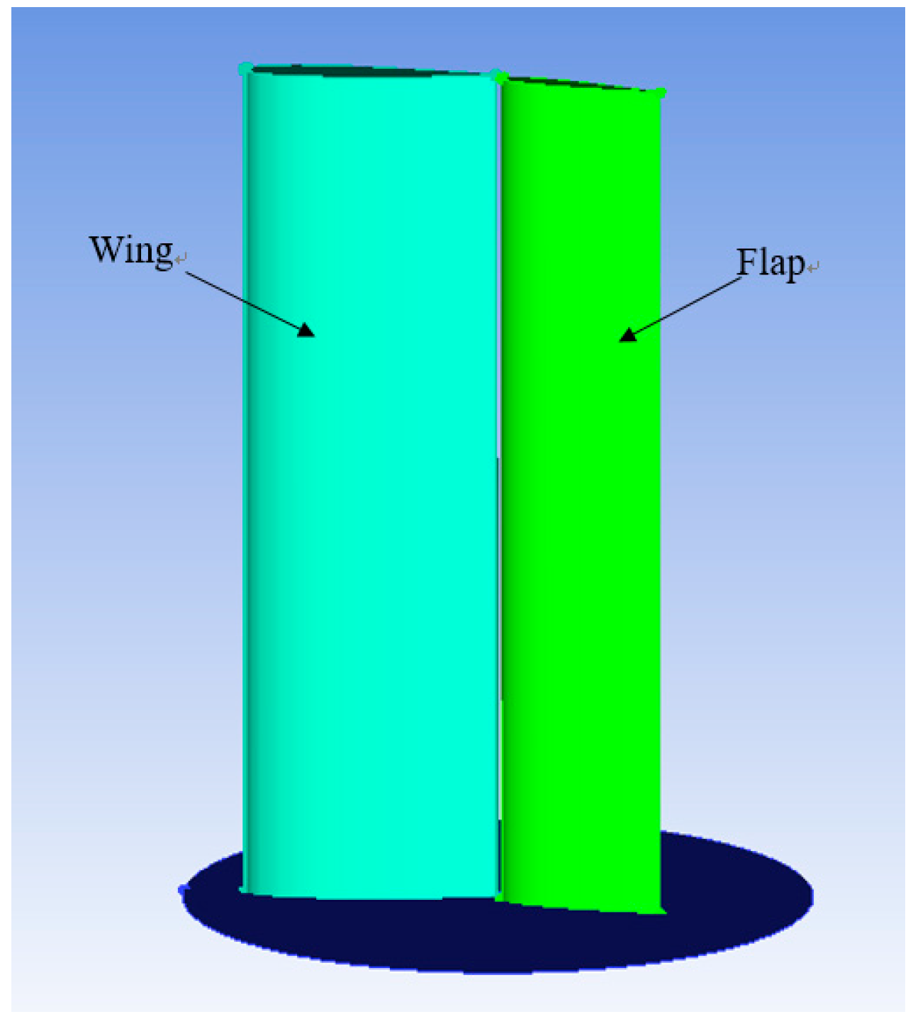
2.1. The Geometry of the Wingsail

The geometry is a simplified configuration of a two-element wingsail with 1/20th model-scale (as Figure 3 and Table 1). The nondimensional number for characterizing the flow of fluid Reynolds number is defined by Equation (1):
R e = ρ v c μ
where μ is the viscosity coefficient of air. The results of naca0018 airfoil with Re = 5 × 10⁵ (the wind speed is assumed to be 20 m/s) are compared with the existing experiments to ensure the accuracy of the numerical results. The general view of the geometry and its characteristic parameters are as follows:
The aim of this paper is to understand the influence of geometric parameters on aerodynamic performance. The parametric design of the wingsail is selected and described in Figure 4. In order to simplify the general problem, it has been decided to focus on the flap deflection angle d, the position of flap rotation axis in the direction of the wing chord Xr, and flap thickness e2/c2. The angle of attack (α) of the wing represents the angle of attack (AOA) of the wingsail, as seen in Figure 4.
Based on the preliminary simulation and previous research [11,18], the initial wingsail configuration has chord ratio c1/c2 = 3:2, wing thickness e1/c1 = 18%, flap thickness e2/c2 = 15%, one flap rotation axis Xr/c1 = 85%, slot width g/c1 = 2.4%. Its name will be r1.5t1815 X85g2.4. Adding the angle of attack (α) and flap deflection angle (d) after this name, and the full configuration name of the wingsail will be r1.5t1815 X85g2.4α6 d15, for α = 6°, d = 15°.

2.2. The Grid Structure

Computational Domain. Before mesh generation, the calculation domain of geometric model should be determined. The computational domain of wingsail is large enough (32c × 30c × 10c) to consider the side effect as negligible (Figure 5). AOA is adjusted by rotating the direction of the airflow. The chord of the wingsail is 0.35 m and the span 0.7 m. In order to simplify the model, the atmospheric boundary layer is not considered. The boundary conditions used are velocity inlets on three sides (inlet, starboard boundary, port boundary) and a static pressure outlet equal to the far-field pressure. The velocity at the inlet is uniform, and the value is the same as the free flow velocity. The wingsail surface and the bottom surface of the computational domain are defined as anti-slip walls.
Mesh Details. The quality of grid determines the accuracy of numerical results. Particular attention has been paid to refine the mesh in the slot, being a region of interaction between the wake of the wing, flow from the slot and the flap boundary layer. Mesh resolution close to the slot has been encrypted as shown in Figure 6. In addition, the mesh size of the flap leading-edge curve is set as 0.4545% (in the case of mesh number 9.86M). In order to ensure the accurate simulation of the flow field near the wall, the height of the first grid cell closest to the wall should be suitable. The nondimensional wall distance for a wall-bounded flow y+ is defined by Equation (2):
y + = y u τ ν = ρ y μ τ w a l l ρ = y ρ μ ( u y ) y = 0
where y is the distance from the first mesh cell to the nearest wall. In this paper, y is specified as 2.871 × 10⁻⁵ c on the wingsail surface. In this case, the profile of the dimensionless wall distance y+ on the surface of the wingsail with AOA = 6° is shown in Figure 7. It can be seen that the value of y+ on the sail surface is about 1, ensuring the accuracy of numerical calculation results. The growth ratio of the prism layer is 1.2. The total number of nodes in the grid is about 9.86 million.
Mesh Independence. It is considered a necessary step to analyze the influence of grid characteristics. When Re = 5 × 10⁵, four different grid numbers (including 2.57, 4.22, 9.86 and 14.4M) are used to estimate the grid sensitivity. In the case of AOA = 6°, the grid independence analysis is carried out with steady Reynolds Average N-S equation and AOA = 15° with URANS. Figure 8 reports the lift and drag coefficients of the unmodified sail model. As shown in Figure 8, the number of grids has a great influence on the lift coefficient, and the error of lift coefficient is less than 0.3% between 9.86 and 14.4M. Based on these calculations, the increase in the number of grids (relative to the case of 9.86M) results in a small change in lift. And the drag coefficient, whose change can be considered as acceptable. Therefore, the grid number of 9.86M is used in this study.
In order to further verify the reliability of the grid with URANS, the influence on the flow field with different grid sizes is also analyzed when Re = 5 × 10⁵ and AOA = 15°. For four different grids (including 2.57, 4.22, 9.86 and 14.4M), the velocity vector on the x–y plane is shown in Figure 9. It can be observed that there is a large separation vortex on the suction surface of the flap and a small vortex on the wake of the wing, which is generated by grids of 9.86 and 14.4M, respectively, but there is no obvious flow separation for grids of 2.57 and 4.22M. There was no significant difference in the flow profile between 9.86 and 14.4M. Therefore, the grid number of 9.86M is suitable for the research of wingsail 3D.

2.3. Computational Approach

Numericalmethod. Menter [20] established the k-ω turbulence model of shear stress transport (SST). Hassan [21] compared the numerical predicted results of standard, RNG and realizable K-ε, standard and SST K-ω models with the experimental data, and found that the K - ω SST model is the most accurate prediction model. So the steady Reynolds Averaged Navier–Stokes(RANS) equations are solved thanks to ANSYS Fluent finite-volume solver with low angle of attack before stall occurs; then, the unsteady Reynolds Average N-S equation is used based on the SST K-ω models when physical instabilities exist [22,23]. As the low Reynolds number is based on the chord of the wingsail (Re = 5 × 10⁵), the fluid is considered as incompressible (the Mach number of the inlet is about 0.062). These models are assigned solvers which control the number of the time step. The selected time step size is computed in the case of CFL = V∆t/∆x = 1. The impact of time models on the aerodynamic performance of the wingsail is investigated at Re = 5 × 10⁵(i.e., V = 20.87 m/s), and the mesh size of the leading-edge curve of the flap is taken as the length interval (i.e., ∆x = 5 × 10⁻⁴ m). Therefore, the magnitude of the time step ∆t is set at a value of 2.5 × 10⁻⁵ s in this simulation investigation. The turbulence intensity at inlet is 1%. The discrete format is quick. Simple algorithm is adopted for the pressure velocity coupling scheme [24].
Model validation. In order to verify the numerical results, the lift coefficient of the two-dimensional wingsail model in a free flow environment is compared with the experimental results, as shown in Figure 10. Daniel [11] had carried out experimental research on the lift/drag characteristics of naca0018 wing.
In the case of Re = 5 × 10⁵, the RANS method is verified. Before stall (AOA < 15°), the numerical calculation results of the lift coefficient and drag coefficient are close to the experimental values, and the estimation error is less than 5%. At the same time, the prediction of the position of the stall angle is accurate. Although the results of numerical prediction are different from the experimental values after stall, it is acceptable that the 2D numerical calculations used for the qualitative study of the lift/drag characteristics of the wingsail.

3. Numerical Results

3.1. Two-Dimensional Wingsail Configurations Study

The lift force and drag force are converted into dimensionless lift coefficient CL and drag coefficient CD, respectively. They are defined as follows:
C L = L 0.5 ρ v 2 A R
C D = D 0.5 ρ v 2 A R
where L and D are the lift force and drag force of the wingsail, respectively. AR is the aspect area of wingsail, include the wing and flap. The lift coefficient and drag coefficient characteristics of wingsail with different geometric parameters are compared.
Camber andthe rotation axis of the flap effect: as the key parameter, the rotating axis position of the flap in the direction of the wing chord Xr is selected as 75% and 85%; five cambers (d = 5°, 10°, 15°, 20°, 25°) have been selected as Figure 11.
When Xr is 85%, the stall does not occur advance with the increase of flap deflection angle at low camber as Xr is 75%. It can be illustrated that the slot width with Xr = 75% exceeds that with Xr = 85% due to the coupling between the camber of the wingsail and the slot width (as Figure 12). The fluid through the slot is enough to supplement the loss of the wing wake, then delay the stall. When the flap deflection angle is more than 15°, the stall angle begins to reduce, which is caused by flow separation of the wing wake, then the flap stalls. The maximum lift coefficient of the wingsail is 2.29 when the flap deflection angle is 20° with AOA = 12°. However, due to the reduction of stall angle, the comprehensive performance of the wingsail with d = 20° is not as good as that with d = 15°. When the flap deflection angle adds to 25°, the lift coefficient decreases in the range of full angles of attack, which may be caused by the stalls. Therefore, it is necessary to consider the rotating axis position of the flap, flap deflection angle and slot width when choosing flap geometry parameters.
Camber and flap thickness effect: Nine selected simulations are summarized in Table 2 to illustrate the coupling between the camber (flap deflection) and the thickness of the flap. It can be seen that the flap thickness (e2/c2) has little effect on the lift and drag coefficients of d = 5° and 15° (low camber), but has significant effect on d = 25° (high camber) which shows the nonlinear coupling between flap thickness and flap deflection angle.
For high camber, the thickening flap leads to an increase of the leading-edge radius which decreases the pressure coefficient suction peak and has postponed the stall of the wingsail. It emphasizes the complexity of the slot flow of a two-element wingsail through the strong coupling between flap deflection, thickness and slot width. The slot effect may be useful to recall some famous papers with Gentry [25] and Smith [26] which illustrate the complex effect among the wing wake, the leakage flow from the slot and the flap boundary layer as may be seen in Figure 13. Therefore, the slot of the wingsail includes a strong design constraint which include the rotating axis position of the flap, flap deflection, flap thickness and slot width.

3.2. Three-Dimensional Study about Effect of Flap Rotation Axis Position

3.2.1. Aerodynamic Performance

The three-dimensional flow around the wingsail at low camber (d = 15°) and high camber (d = 25°) is studied in detail. In order to better study the effect of the rotating axis position of the flap on the aerodynamic characteristics and delayed stall of the wingsail, we analyzed the lift characteristics of the wingsail when the rotating axis of the flap is located at different positions of the wing chord (Xr = 75%, 80%, 85%, 90% and 95%) at α = 6° and 15°.
Figure 14 shows the lift characteristics for different rotating axis positions of the flap. The position of flap rotating axis has little effect on lift coefficient at α = 6° (stall has not yet occurred) with low camper. The lift coefficient first increases and then reduces with the position of flap rotation axis moving backward; especially from 80% to 85%, it drops suddenly at α = 15° (stall has occurred). It can be illustrated that the change is caused by the flow separation of the wing wake and the flap suction surface from Figure 16. At α = 6° with high camber, the lift coefficient increases with the position of the flap rotating axis moving backward, especially from 85% to 95%. It can be explained from Figure 17b that the flow separation on the suction surface of the flap has disappeared.

3.2.2. Streamlines

As for the wingsails with different rotating axis positions of the flap at α = 15° and d = 15°, the streamlines on the mid-span of wingsail are depicted in Figure 15. It can be found that a small separation vortex appears in the wake of the wing and a large separation vortex appears in the regions over the suction surface of the flap at Xr = 90%.
Figure 16 shows the limiting streamline and static pressure contours on suction surface for two-element wingsail at different rotating axis positions of the flap. With the backward movement of the rotating axis position of the flap, the flow separation of the suction surface of the wing expands from the blade root to the top, and the return area becomes larger for the low camber wingsail. The flow separation line appears on the suction surface of the wing at Xr = 85%. It explains that the forward movement of the rotating axis position of the flap increases the fluid flow through the slot, delays the flow separation of the suction surface of the wing, or delays stall of the wingsail. An obvious separation helix appears on the suction surface of the wing at Xr = 95%, which indicates that the vortex has been formed. When the rotating axis position of the flap is moves backward from 90% to 95%, the flow separation on the suction surface of flap disappears. We guess the fluid flowing through the smaller gap does not supplement the wake of the wing, but flows along the flap boundary layer.

3.2.3. Velocity Magnitude Contours

It can be seen from Figure 17 that the suction surface of the wing has a large flow separation at α = 15° with low camber. At Xr = 85%, the fluid flowing through the slot complements the flow separation of the wing wake and the flap suction surface. There is no vortex in the mid-span of the wingsail. The slot jet can be observed clearly at Xr = 90%. As a result of the reduced slot width due to the rotating axis position of the flap backward, the slot jet only divides the vortex of the wing wake and there is a large-scale flow separation on the suction surface of the flap, which causes deep stall of the flap. This phenomenon has also been observed and described in Biber [27] and Chapin [18]. Because of the smaller slot width at Xr = 95%, the slot jet only flows along the boundary layer of the flap, which has little effect on the separation flow of the wing wake. If the slot is further reduced or not set, the flap setting may aggravate the separation of the wing wake, such as the research of the hybrid sail designed by Qiao Li [14]. However, the forward movement of the rotating axis position of the flap is limited by the flap deflection angle. As shown in Figure 18, when the rotating axis position of the flap moves forward from 90% to 85% at α= 6°, the large-scale flow separation occurs on the suction surface of the flap, as the phenomenon seen by Fiumara [19] in the two-element sail experiment in 2016.

4. Conclusions

By studying the influence of flap geometric parameters on the aerodynamic characteristics of two-element wingsail under steady and unsteady conditions, two-dimensional and three-dimensional related parameters were simulated using the same Reynolds number (Re = 5 × 10⁵).
The 2D simulation results show that, when the rotating axis position of the flap is located at 85% of the wing chord, the thickening flap leads to an increase of the leading-edge radius which decreases the pressure coefficient suction peak and has postponed the stall of the wingsail for high camber. It reflects the nonlinear coupling effect between wingsail camber and flap thickness. When the rotating axis of the flap is located at the 75% of the wing chord, the stall angle is delayed with the increase of the flap deflection angle at low camber. When selecting the geometric parameters of the flap, factors such as the position of the flap rotation axis, the flap deflection angle, and the flap thickness need to be considered comprehensively.
The 3D simulation mainly studies the influence of the flap rotating axis position and the flap deflection angle on the stall characteristics of the wingsail. When stall has not yet occurred with low camber, the rotating axis position of the flap has little effect on the lift coefficient, while stall has occurred, the lift coefficient increases first and then reduces with the rotating axis position of the flap moving backward. The flow separation of the suction surface of the wing expands from the root to the top and the return area becomes larger, especially from the 80% to the 85%, the lift coefficient drops suddenly. This is caused by the flow separation between the wing wake and the flap suction surface. At high camber with AOA = 6°, the lift coefficient always increases with the position of the flap rotation axis, especially from 85% to 95%, the lift coefficient suddenly rises, which is caused by the disappearance of large-scale flow separation of the flap suction surface.
Therefore, the slot width is an important factor affecting the flow separation of the wing wake and the suction surface of the flap, where size is affected by the rotating axis position of the flap and the flap deflection angle. When the flap deflection angle is adjusted to obtain a large lift coefficient, the restriction of the rotating axis position of the flap must be considered to ensure a reasonable stall angle range.

Author Contributions

Conceptualization, C.L. and H.W.; investigation, C.L. and H.W.; methodology, C.L. and P.S.; software, C.L.; writing—original draft preparation, C.L.; writing—review and editing, H.W.; supervision, P.S. All authors have read and agreed to the published version of the manuscript.

Funding

This research was funded by National Natural Science Foundation of China, 51709165, Research Funds of Jiangsu Maritime Institute, 014070, kjcx-1907.

Conflicts of Interest

The authors declare no conflict of interest.

Nomenclature

ReReynolds number [-]
αAngle of attack of the main wing (AOA) [°]
ctotal chord of the wingsail [m]
c1chord of the main wing [m]
c2chord of the flap [m]
CDDrag coefficient [-]
CLLift coefficient [-]
dFlap deflection angle [°]
gnon-dimensional slot width (g/c1) [-]
e1thickness of the main wing [m]
e2thickness of the flap [m]
ARThe aspect area of wingsail [m2]
y+Non-dimensional wall distance [-]
ρThe density of the air [kg/m3]
zThe height of wingsail in the vertical direction [m]
hWingsail height [m]
LLift force [N]
DDrag force [N]
vThe velocity of inflow [m/s]
XrThe position of flap rotation axis in the direction of the wing chord [-]

References

  1. Ishihara, M.; Watanabe, T.; Shimizu, K.; Yoshimi, K.; Namura, H. Prospect of sailequipped motor ship as assessed from experimental ship Daioh. In Proceedings of the Shipboard Energy Conservation Symposium; Society of Naval Architects and Marine Engineers: New York, NY, USA, 1980; pp. 181–198. [Google Scholar]
  2. Available online: http://www.sohu.com/a/275284498_100091571 (accessed on 14 November 2018).
  3. Blakeley, A.W.; Flay, R.G.J.; Richards, P.J. Design and Optimisation of Multi-Element Wing Sails for Multihull Yachts. In Proceedings of the 18th Australasian Fluid Mechanics Conference, Tasmania, Australia, 3–7 December 2012. [Google Scholar]
  4. Available online: http://k.sina.com.cn/article_6424865154_17ef3a982001001t6p.html (accessed on 20 December 2017).
  5. Kind, R.J. An Experimentel Investigation of a Low- Speed Circulation Controlled Airfoil. Aero. Quart. 1968, 19, 170–182. [Google Scholar] [CrossRef]
  6. Seifert, A.; Bachar, T.; Koss, D.; Shepshelovich, M.; Wygnanski, I. Oscillatory Blowing: A Tool to Delay Boundary-Layer Separation. AIAA J. 1993, 31, 2052–2060. [Google Scholar] [CrossRef]
  7. Seifert, A.; Darabi, A.; Wyganski, I. Delay of airfoil stall by periodic excitation. J. Aircr. 1996, 33, 691–698. [Google Scholar] [CrossRef]
  8. Kralj, D.M.; Klarin, B. Wing Sails for Hybrid Propulsion of a Ship. J. Sustain. Dev. Energy Water Environ. Syst. 2016, 4, 1–13. [Google Scholar] [CrossRef] [Green Version]
  9. Marine, B. E-ShiP1 with Sailing Rotors to Reduce Fuel Costs and to Reduce Emissions. Available online: http://www.marinebuzz.com (accessed on 28 August 2008).
  10. Borglund, D.; Kuttenkeuler, J. Active Wing Flutter Suppression Using A Trailing Edge Flap. J. Fluids Struct. 2002, 16, 271–294. [Google Scholar] [CrossRef]
  11. Daniel, W.A. The CFD Assisted Design and Experimental Testing of a Wingsail with High Lift Devices; University of Salford: Salford, UK, 1996. [Google Scholar]
  12. Carr, L.W.; McAlister, K.W. The effect of a leading-edge slat on the dynamic stall of an oscillating airfoil. AIAA Pap. 1983, 83, 2533. [Google Scholar]
  13. Available online: http://cookeassociates.com/sports/commercial,php (accessed on 6 August 2015).
  14. Li, Q.; Nihei, Y.; Nakashima, T.; Iked, Y. A study on the performance of cascade hard sails and sail-equipped vessels. Ocean Eng. 2015, 98, 23–31. [Google Scholar] [CrossRef]
  15. Fish, F.E.; Battle, J.M. Hydrodynamic design of the humpback whale flipper. J. Morphol. 1995, 225, 51–60. [Google Scholar] [CrossRef] [PubMed]
  16. Toshifumi, F.; Koichi, H.; Michio, U.; Nimura, T. On aerodynamic characteristics of a hybrid-sail with square soft sail. In Proceedings of the International Offshore and Polar Engineering Conference, International Society of Offshore and Polar Engineers, Honolulu, HI, USA, 25–30 May 2003; pp. 2576–2583. [Google Scholar]
  17. Fujiwara, T.; Hirata, K.; Ueno, M.; Nimura, T. On the development of high-performance sails for an ocean-going sailing ship. In Proceedings of the International Conference on Marine Simulation and Ship Manoeuvrability, MARSIM’03, Kanazawa, Kanazawa, Japan, 25–28 August 2003. RC-23-1–9. [Google Scholar]
  18. Chapin, V.; Gourdain, N.; Verdin, N. Aerodynamic Study of a Two-elements Wingsail for High Performance Multihull Yachts. In Proceedings of the 5th High Performance Yacht Design Conference Auckland, Auckland, New Zealand, 10–12 March 2015. [Google Scholar]
  19. Fiumara, A.; Gourdain, N.; Chapin, V.; Senter, J.; Bury, Y. Numerical and experimental analysis of the flow around a two-element wingsail at Reynolds number 0.53 × 10⁶. Int. J. Heat Fluid Flow 2016, 62, 538–551. [Google Scholar] [CrossRef] [Green Version]
  20. Menter, F.R. Two-equation eddy-viscosity turbulence models for engineering applications. AIAA J. 1994, 32, 1598–1605. [Google Scholar] [CrossRef] [Green Version]
  21. Hassan, G.E.; Hassan, A.; Youssef, M.E. Numerical Investigation of Medium Range Re Number Aerodynamics Characteristics for NACA0018 Airfoil. CFD Lett. 2014, 6, 175–187. [Google Scholar]
  22. Malan, P.; Suluksna, K.; Juntasaro, E. Calibrating the γ-Reθ Transition Model for Commercial CFD. In Proceedings of the 47th AIAA Aerospace Science Meeting, Orlando, FL, USA, 5–8 January 2009. [Google Scholar]
  23. Douvi, C.E.; Tsavalos, I.A.; Margaris, P.D. Evaluation of the Turbulence Models for the Simulation of the Flow Over a National Advisory Committee for Aeronautics (NACA) 0012 Airfoil. Mech. Eng. Res. 2012, 4, 100–111. [Google Scholar]
  24. Rhee, S.H.; Kim, H. A suggestion of gap flow control devices for the suppression of rudder cavitation. J. Mar. Sci. Technol. 2008, 13, 356–370. [Google Scholar] [CrossRef]
  25. Gentry, A. The Aerodynamic of Sail Interaction. In Proceedings of the 3th AIAA Symposium on the Aero/Hydronautics of Sailing, Redondo Beach, CA, USA, 20 November 1971. [Google Scholar]
  26. Smith, A.M.O. High-Lift Aerodynamics. J. Aircr. 1975, 12, 501–530. [Google Scholar] [CrossRef] [Green Version]
  27. Biber, K.; Zumwalt, G. Experimental studies of a two-element airfoil with large separation. In Proceedings of the 30th Aerospace Sciences Meeting and Exhibit, Reno, NV, USA, 6–9 January 1992. [Google Scholar] [CrossRef]
Figure 1. “Kaili” VLCC with wingsail.
Jmse 08 00333 g001
Figure 2. Capsizing accident of sailboat.
Jmse 08 00333 g002
Figure 3. The geometry and simplified configuration of the two-element wingsail.
Jmse 08 00333 g003
Figure 4. Wingsail geometry and parameterization.
Jmse 08 00333 g004
Figure 5. Box domain for the freestream simulation.
Jmse 08 00333 g005
Figure 6. The encrypted mesh in (a) mid-span and (b) bottom wallof the slot.
Jmse 08 00333 g006
Figure 7. Wall y+ contour on wingsail surface (AOA = 6 deg).
Jmse 08 00333 g007
Figure 8. Convergence of (a) lift and (b) drag coefficients as a function of mesh number.
Jmse 08 00333 g008
Figure 9. Flow profiles on the mid-span of wingsail with different grid numbers of (a) 2.57M, (b) 4.22M, (c) 9.86M and (d) 14.4M (AOA = 15 deg).
Jmse 08 00333 g009
Figure 10. Comparison of lift coefficient (a) and drag coefficient (b) between test and CFD.
Jmse 08 00333 g010
Figure 11. Convergence of lift coefficients as a function of AOA and flap deflection angle with (a) Xr = 85% and (b) Xr = 75%.
Jmse 08 00333 g011
Figure 12. The slot width with Xr = 85% and 75%.
Jmse 08 00333 g012
Figure 13. The streamlines in the slot region (URANS).
Jmse 08 00333 g013
Figure 14. Lift coefficient versus flap rotation axis position of the wingsail in low and high camber configuration.
Jmse 08 00333 g014
Figure 15. Streamlines at mid-span of the wingsail at (a) Xr = 75% (b) Xr = 85% (c) Xr = 90% and (d) Xr = 95% with α = 15°, d = 15°.
Jmse 08 00333 g015
Figure 16. Limiting streamline and static pressure contours on suction surface for the two-element wingsail at (a) Xr = 75% (b) Xr = 80% (c) Xr = 85% (d) Xr = 90% and (e) Xr = 95% with α = 15°, d = 15°.
Jmse 08 00333 g016
Figure 17. Velocity magnitude contours at mid-span of wingsail at (a) Xr = 85% (b) Xr = 90% and (c)Xr = 95% with α = 15°, d = 15°
Jmse 08 00333 g017
Figure 18. Velocity magnitude contours at mid-span of wingsail at (a) Xr = 85% (b) Xr = 90% and (c) Xr = 95% with α = 6°, d = 25°.
Jmse 08 00333 g018aJmse 08 00333 g018b
Table 1. Parameterization of wingsail.
c0.35 m
h0.7 m
Re5 × 105
d0–25°
α0–20°
g2.4%
Xr75%–95%
Table 2. Results for α = 6° with the SST transitional turbulence model.
Configurationse2/c2dCLCDL/D
r1.51815x0.85g2.4α6d515%1.0050.021347.16
r1.51815x0.85g2.4α6d1515%15°1.7240.033850.94
r1.51815x0.85g2.4α6d2515%25°1.9510.0632.53
r1.51812x0.85g2.4α6d512%1.0020.020748.5
r1.51812x0.85g2.4α6d1512%15°1.730.033651.47
r1.51812x0.85g2.4α6d2512%25°1.6060.16289.87
r1.51810x0.85g2.4α6d510%1.0020.020848.22
r1.51810x0.85g2.4α6d1510%15°1.740.033751.59
r1.51810x0.85g2.4α6d2510%25°1.6490.164910

