Article

New Theoretical Model of the Irradiance Distribution in Water from a Unidirectional Point Source

Institute of Applied Physics of the Russian Academy of Sciences, 46 Uljanova St., Nizhny Novgorod 603950, Russia
J. Mar. Sci. Eng. 2020, 8(2), 79; https://doi.org/10.3390/jmse8020079
Submission received: 29 November 2019 / Revised: 7 January 2020 / Accepted: 21 January 2020 / Published: 25 January 2020
(This article belongs to the Special Issue Light Fields in the Ocean from Natural and Artificial Sources)

Abstract

:
Formulas are presented for calculating the irradiance field, which is formed in a turbid medium with a narrow scattering phase function and homogeneous optical properties when an infinitely narrow light beam passes through it. The calculations are based on a new mathematical model of the stationary radiation field of an omnidirectional point source and relationships enabling one to represent the irradiance distribution in a continuous or modulated light beam through this field. The obtained formulas, in contrast to the previously known ones, permit taking into account the temporal spreading of a pulsed light beam in the sea without a significant decrease in the accuracy of describing its spatial structure.

1. Introduction

Analytical models of the beam spread function (BSF), i.e., the light field of an unidirectional point source (UPS), are widely used in the theory of instrumental imaging of underwater objects [1,2,3,4,5,6,7], lidar probing of the ocean [8,9,10,11,12,13,14,15,16,17,18,19], and underwater optical communication. These models are based on approximate solutions of the radiative transfer equation (RTE) simplified by taking into account the water inherent optical properties (IOP). The theory of underwater imaging is mainly based on the RTE solution in the small-angle approximation [20,21,22,23,24,25], which accurately describes the spatial-angular radiance distribution in the axial region of a continuous light beam at optical distances from the source τ < 8 ÷ 12 . However, this solution neglects the effects of multipath propagation of light in the sea, which manifest themselves in the formation of stationary angular distributions of radiance and irradiance in a continuous beam for τ and in a distortion of signals transmitted by a modulated beam. These effects within the framework of the small-angle approximation allow for a more accurate recording of the RTE differential operator [26,27,28,29]. But the “refined” small-angle RTE (with the collision integral) is not strictly solved, while its approximate solution has a rather complicated form. Therefore, the effect of multiple scattering on the characteristics of modulated light beams was mainly studied in the small-angle diffusion approximation [30,31,32,33,34] using the equation obtained from the refined small-angle RTE by replacing its integral operator with a differential one. The small-angle diffusion approximation is applicable when the variance of the angular distribution of radiance is large compared to the angle dispersion of the beam deviation in an elementary scattering event (the radiance should smoothly vary in the scale of the width of the scattering phase function). Therefore, this approximation roughly describes the spatial–angular structure of a narrow light beam, although the integral characteristics of the beam are determined in it with accuracy acceptable for a number of practical applications. Note that to construct models of images of underwater objects and lidar echo signals arriving from the water depth, one mainly uses not the BSF itself but the expression for the irradiance field generated in water by the UPS. In this paper, we propose a new model of this field, which, contrary to the available ones, will allow us to take into account the influence of the photon path dispersion effects on the characteristics of continuous and modulated light beams without significant decrease in the accuracy of describing their spatial structures.
The proposed model is constructed using the optical reciprocity theorem by appropriate replacement of variables in the expression for the radiation field of an omnidirectional point source (OPS). The radiance distribution from OPS is presented as the sum of the first three terms of Neumann series and the term describing the radiance of light scattered more than twice. The first three terms were found from the refined small-angle RTE. To calculate the last term, the small-angle diffusion equation with distributed sources that depend on the radiance of twice scattered light was used. Thus, the OPS field model is a superposition of solutions of two equations, the first of which describes the highly anisotropic field component taking into account the peculiarities of the shape of the water scattering phase function (SPF), and the second describes the weakly anisotropic field component, which depends on the dispersion of the angle of single scattering, and not on the SPF. The formulas for calculating the irradiance distribution in a stationary light beam and the irradiance distribution from a non-stationary UPS (in spectral representation) do not have a very complicated form (the sum of single and double integrals) and therefore are convenient for practical use.

2. Statement of the Problem and Initial Equations

The IOP are characterized by the coefficients of absorption a , scattering b , backscattering b b , forward scattering b 1 = b 2 b b , and attenuation c = a + b , by the single scattering albedo Λ = b / c , and scattering phase function β ( γ ) that is approximately represented as the sum of the narrow β 1 ( γ ) and isotropic β 0 ( γ ) = 1 scattering phase functions
β ( γ ) = ( 1 2 p b ) β 1 ( γ ) + 2 p b β 0 ( γ )
with weight factors depending on the backscattering probability
p b = b b / b = ( 1 / 2 ) π / 2 π β ( γ ) sin γ d γ
We assume that the scattering phase function β 1 satisfies the conditions
( 1 / 2 ) π / 2 π β 1 ( γ ) sin γ d γ < < p b < < 1 ,   ( 1 / 2 ) 0 π β 1 ( γ ) sin γ d γ ( 1 / 2 ) 0 β 1 ( γ ) γ d γ = 1
and characterize its width by the parameter
d β = ( 1 / 2 ) 0 π / 2 γ 2 β 1 ( γ ) γ d γ
We also assume that the UPS with the power P ( t ) is located at the point r = 0 in water and acts in the direction of the unit vector z 0 (see Figure 1a). The light radiance at the point r in the direction of the unit vector Ω at the time t is denoted by L ˜ ( U P S ) ( r , Ω , t ) . The problem is to obtain formulas for calculating the scalar irradiance
E ˜ ( U P S ) ( r , ϑ , t ) = 4 π L ˜ ( U P S ) ( r , Ω , t ) d Ω
as a function of the distance ( r ) from the source to the point r , polar angle ( ϑ ) of this point, and time t .
One of the known methods for solving this problem is based on the use of spectral expansions
P ( t ) = P s ( ω ) exp ( i ω t ) d ω
E ˜ ( U P S ) ( r , ϑ , t ) = E ˜ s ( U P S ) ( r , ϑ , ω ) exp ( i ω t ) d ω
and relation
E ˜ s ( U P S ) ( r , ϑ , ω ) = P s ( ω ) E ( U P S ) ( r , ϑ , a + i ω / c w )
where c w is the light speed in water and E ( U P S ) ( r , ϑ , a ) is the expression for the stationary irradiance field generated by the UPS of the power P = 1 in water with the absorption coefficient a . As Equation (8) shows, to find the harmonic component of the nonstationary irradiance field with the frequency ω , it is necessary to replace the parameter a with a + i ω / c w in the expression for the stationary field, after which the calculation of the nonstationary field is reduced to the calculation of integral (7) if we know the stationary field (below we will not indicate the absorption coefficient a as an argument of the field E ( U P S ) to simplify the formulas).
The integral parameters of the pulsed irradiance field
Δ 1 = t ¯ ( r / c w ) ,   t ¯ = t E ˜ ( U P S ) ( r , ϑ , t ) d t / E ˜ ( U P S ) ( r , ϑ , t ) d t
Δ 2 2 = ( t t ¯ ) 2 E ˜ ( U P S ) ( r , ϑ , t ) d t / E ˜ ( U P S ) ( r , ϑ , t ) d t
which characterize the time of the pulse propagation from the source to the point of its reception and the duration of the received pulse, are found by differentiating the stationary field with respect to the parameter a [33]
t ¯ = 1 c w d d a ln E ( U P S ) ( r , ϑ ) ,   Δ 2 2 = ( Δ t 0 ) 2 + 1 c w 2 d 2 d a 2 ln E ( U P S ) ( r , ϑ )
( Δ t 0 is the radiated pulse duration).
Thus using Equations (6)–(11), the nonstationary irradiance field E ˜ ( U P S ) and its integral characteristics are expressed through the irradiance field E ( U P S ) that is stationary in time. To develop an analytical model of this field, it is expedient to use the optical reciprocity theorem [35], according to which the irradiance from the UPS can be represented as
E ( U P S ) ( r , ϑ ) = 4 π L ( O P S ) ( r , ϑ )
through the light radiance L ( O P S ) ( r , ψ ) from an omnidirectional point source (OPS), which is a function of the distance to the source ( r ) and angle of deviation of the beam from the direction to the source ψ = arccos ( Ω r 0 ) , r 0 = r / r (see Figure 1b). The RTE for this field is strictly written as
[ cos ψ r sin ψ r ψ + c ] L ( O P S ) ( r , ψ ) = S ( r , ψ ) + δ ( r ) 4 π
S ( r , ψ ) = b 4 π 0 π L ( O P S ) ( r , ψ ) [ 0 2 π β ( γ ) d φ ] sin ψ d ψ
γ = arccos ( cos ψ cos ψ + sin ψ sin ψ cos φ )
In this paper, we also use the equations of the “refined small-angle approximation”, which are obtained from (13)–(15) after replacing cos ψ ( 1 ψ 2 / 2 ) , sin ψ ψ on the left-hand side of Equation (13) and writing Equation (14) in the form
S ( r , ψ ) = b 1 4 π 0 L ( O P S ) ( r , ψ ) p ( ψ , ψ ) ψ d ψ
p ( ψ , ψ ) = 0 2 π β 1 ( ψ 2 2 ψ ψ cos φ + ψ 2 ) d φ
The indicated RTE simplifications become possible because of the strong anisotropy of the field L ( O P S ) , which is explained by the narrow scattering phase function in water and significant difference of the parameter Λ from 1. The substitutions b b 1 , β β 1 into Equation (14) mean that we neglect the contribution of isotropically scattered light to the field L ( O P S ) and assume that water acts on this field as a medium with the scattering coefficient b 1 = b 2 b b and absorption coefficient a 1 = a + 2 b b .

3. Model of the OPS Light Field

The field L ( O P S ) is given as
L ( O P S ) = n = 0 2 L n ( O P S ) + L m s ( O P S )
where L n ( O P S ) is the radiance of n -multiple scattered light and L m s ( O P S ) is the radiance of light scattered more than twice (we call it multiple scattered). Similar expressions for the field were used earlier in solving other problems of the optics of turbid media [32,33,34,36].

3.1. Formulas for Calculating the Radiances of Single and Double Scattered Light

It follows from exact Equations (13)–(15) that the radiance of nonscattered light is determined by the formula
L 0 ( O P S ) ( r , ψ ) = exp ( c r ) 4 π 2 r 2 ψ δ ( ψ )
while series terms (18) with the index n > 0 are found from the recurrence relations
Q n ( r , ψ ) = b 4 π 0 π L n 1 ( O P S ) ( r , ψ ) [ 0 2 π β ( γ ) d φ ] sin ψ d ψ
L n ( O P S ) ( r , ψ ) = 0 Q n ( r 1 , ψ 1 ) exp ( c s ) d s
r 1 = r 2 2 r s cos ψ + s 2 ,   ψ 1 = a r c t g r sin ψ r cos ψ s
Expressions for the functions L n ( O P S ) in the refined small-angle approximation can be found from (20) to (21) by the replacements b b 1 , β β 1 and replacement of Equation (22) with approximate equations
r 1 r s + r s ψ 2 2 ( r s ) ,   ψ 1 r ψ r s
Equation (23) for r 1 should be used only when substituting it into the exponential factor of the function Q n containing a water attenuation coefficient. When substituting r 1 into the factors that do not contain an attenuation coefficient, we can assume that r 1 = r s . The functions Q 1 , L 1 ( O P S ) and Q 2 , L 2 ( O P S ) found in this way have the form
Q 1 ( r , ψ ) = b 1 exp ( c r ) ( 4 π r ) 2 β 1 ( ψ )
L 1 ( O P S ) ( r , ψ ) = b 1 exp ( c r ) ( 4 π ) 2 r ψ q ( r , ψ )
q ( r , ψ ) = 0 β 1 ( γ + ψ ) exp ( c r ψ γ / 2 ) d γ
Q 2 ( r , ψ ) = b 1 2 exp ( c r ) ( 4 π ) 3 r 0 p ( ψ , ψ ) q ( r , ψ ) d ψ
L 2 ( O P S ) ( r , ψ ) = b 1 2 ( 4 π ) 3 0 exp [ c r ( 1 + ψ α / 2 ) ] [ 0 p ( α + ψ , ψ ) q ( r 2 , ψ ) d ψ ] d α α + ψ
r 2 = r ψ [ ( α + ψ ) 1 + ( α / 2 ) ]

3.2. Equation for the Radiance of Multiple Scattered Light

To obtain the field L m s ( O P S ) we use the differential equation
D ^ L m s ( O P S ) ( r , ψ ) = Q 3 ( r , ψ )
D ^ = [ r ψ r ψ + a 1 ( 1 + ψ 2 / 2 ) D ( 2 ψ 2 + 1 ψ ψ ) ] ,   D = 1 4 d β b 1
yielded by (13)–(15) when the variance of the angular distribution of radiance
d L ( r ) = 0 π ψ 2 L m s ( O P S ) ( r , ψ ) sin ψ d ψ / 0 π L m s ( O P S ) ( r , ψ ) sin ψ d ψ
satisfies the conditions d β < < d L < < 1 . Equation (30) with the OPS has a self-similar solution in the form of a Gaussian function of the angle ψ with parameters depending on r [32]. To obtain a similar expression for the field L m s ( O P S ) , we replace its source
Q 3 ( r , ψ ) = b 1 4 π 0 L 2 ( O P S ) ( r , ψ ) p ( ψ , ψ ) ψ d ψ
with the source
Q ˜ 3 ( r , ψ ) = M ( 0 ) π ψ 0 2 exp [ ψ 2 / ψ 0 2 ] ,   ψ 0 2 = M ( 2 ) / M ( 0 )
whose angular moments coincide with those of source (32):
M ( m ) ( r ) = 2 π 0 ψ m Q 3 ( r , ψ ) ψ d ψ ( m = 0 , 2 )
The function M ( m ) is given as
M ( 0 ) ( r ) = b 1 L 2 ( 0 ) ( r ) ,   M ( 2 ) ( r ) = b 1 [ d β L 2 ( 0 ) ( r ) + L 2 ( 2 ) ( r ) ]
through the angular moments of the fields L n ( O P S )
L n ( m ) ( r ) = 2 π 0 ψ m L n ( O P S ) ( r , ψ ) ψ d ψ
To simplify their calculation, we used the equations that follow from the RTE in the refined small-angle approximation:
( r + 2 r + c ) L n ( 0 ) = b 1 L n 1 ( 0 ) + 1 2 L n ( 2 ) r
( r + 4 r + c ) L n ( 2 ) = b 1 d β L n 1 ( 0 ) + b 1 L n 1 ( 2 ) + 1 2 L n ( 4 ) r
L 0 ( 0 ) = ( 4 π r 2 ) 1 exp ( c r ) , L 0 ( 2 ) = 0
First, we solved the set of Equations (37) and (38) with neglected last terms and then the expression for the moment L 2 ( 0 ) was refined by substituting the previously found functions L n ( 2 ) into Equation (37). As a result, from (37)–(39) and (35) we obtained the expressions for the parameters of the function Q ˜ 3 :
M ( 0 ) ( r ) = ( 8 π ) 1 b 1 3 ( 1 d β / 3 ) exp [ c r ( 1 + d β / 6 ) ] ,   ψ 0 2 = 5 3 d β

3.3. Formulas for Calculating the Radiance of Multiple Scattered Light

If ψ 0 2 < < 1 , the solution of Equation (30) with a distributed source Q 3 can be represented as
L m s ( O P S ) ( r , ψ ) = 0 r L ( r 0 , r , ψ ) d r 0
through the solution of the equation
D ^ L ( r 0 , r , ψ ) = 0
with the boundary condition
L ( r 0 , r 0 , ψ ) = Q 3 ( r 0 , ψ ) M ( 0 ) ( r 0 ) π ψ 0 2 exp [ ψ 2 / ψ 0 2 ]
If the solution of Equation (42) is sought as
L ( r 0 , r , ψ ) = E ( r 0 , r ) π V ( r 0 , r ) exp [ ψ 2 / V ( r 0 , r ) ]
then for the functions E and V we obtain the equations
d V / d r + 2 V / r + a 1 V 2 / 2 = 4 D
d ( ln E ) / d r + a 1 + 2 / r + a 1 V / 2 = 0
with the boundary conditions
E ( r 0 , r 0 ) = M ( 0 ) ( r 0 ) ,   V ( r 0 , r 0 ) = ψ 0 2
As is seen in Equation (45), for r , the function V (variance of the angular distribution of radiance) takes the stationary value [21]
V = 8 D / a 1 = 2 d β b 1 / a 1
Passing to a new variable in Equation (45)
ς = ( V / 2 ) a 1 r
we obtain the equation for the function U = V / V
d U / d ς + 2 U / ς + U 2 = 1
having a solution of the form
U ( r 0 , r ) = c t h ( ς η ) ( 1 / ς )
with the parameter η ( r 0 ) that is found from the condition
c t h ( ς 0 η ) ) ( 1 / ς 0 ) = ψ 0 2 / V ,   ς 0 = ( V / 2 ) a 1 r 0
As a result, we have
η ( r 0 ) = ς 0 + 1 2 ln ν 1 ν + 1 ,   ν ( r 0 ) = ( ψ 0 2 / V ) + ( 1 / ς 0 )
V ( r 0 , r > r 0 ) = V [ ( ν + 1 ) exp [ 2 ( ς ς 0 ) ] + ( ν 1 ) ( ν + 1 ) exp [ 2 ( ς ς 0 ) ] ( ν 1 ) 1 ς ]
The function E is found from Equation (46) after substituting the expression for V into it:
E ( r 0 , r > r 0 ) = 2 M ( 0 ) ( r 0 ) ( r 0 / r ) exp [ a 1 ( r r 0 ) ] ( ν + 1 ) exp ( ς ς 0 ) ( ν 1 ) exp ( ς 0 ς )
Thus the calculation of the radiance of multiple scattered light is reduced to the calculation of single integral (41) of the function L whose form is determined by Equations (44), (54), (55), and (40), (53).
To calculate the field L ( O P S ) for ς 1 , one can use simpler formulas [32].
L ( O P S ) = E ( r ) π V ( r ) exp [ ψ 2 / V ( r ) ] ,   E = exp ( a 1 r ) 4 π r 2 ( ς s h ς ) ,   V = V [ c t h ς ( 1 / ς ) ]
showing, in particular, that for ς , the variance of the angular distribution of radiance V tends to the stationary value V , while the irradiance attenuates according to the formula
E = ( a 1 V / 4 π r ) exp ( α r ) ,   α = a 1 ( 1 + V / 2 )
The model of the field L ( O P S ) described above is applicable if V < < 1 .

4. Simulation of the Structure of a Narrow Light Beam in Water

Using Equation (12), the irradiance distribution in a narrow light beam is represented through the radiance of the light field of the OPS. According to Equation (18), the radiance of this field is the sum of the radiance of nonscattered light (Equation (19)) and the radiance of single (Equation (25)), double (Equation (28)), and multiple (Equation (41)) scattered light. The expressions for these components of the light field are quite simple with the exception of Equation (28) that contains a quadruple integral. This formula can be simplified by using such approximations of the water scattering phase function, which allows one to analytically calculate integrals (17), (26) or approximate them by elementary functions. Such a possibility appears, in particular, when the scattering phase function is given in the form
β 1 ( γ ) = p 1 exp ( γ / γ 1 ) + p 2 exp ( γ / γ 2 )
(a more complex SPF with one exponential term is described in the paper [37]). This scattering phase function is characterized by four parameters that are connected to each other and to the parameter d β by the relations
p 1 = 6 γ 2 2 d β 3 γ 1 2 ( γ 2 2 γ 1 2 ) ,   p 2 = d β 6 γ 1 2 3 γ 2 2 ( γ 2 2 γ 1 2 )
The substitution of (58) into (26) yields
q ( r , ψ ) = n = 1 2 p n exp ( ψ / γ n ) γ n 1 + c r ψ / 2
Integral (17) with scattering phase function (58) cannot be taken analytically but with an acceptable error (of the order of 5%) is presented in the form
p ( ψ , ψ ) = n = 1 2 2 p n { π exp [ γ n 1 ( ψ 4 + ψ 4 ) 1 / 4 ] + t h ( 0.35 γ n 1 ψ ψ ) 1 + 0.8 γ n 1 ψ ψ }
In the calculations, we assumed that
p 1 = 62 / d β , p 2 = 3.34 / d β , γ 1 = d β 1 / 2 / 8 , γ 2 = d β 1 / 2 / 1.8
so that function (58) reproduces the shape of one of the real scattering phase functions measured in the Black Sea. Other IOPs were expressed via attenuation coefficient according to Levin–Kopelevich empirical regressions for the “Case 2” water at a wavelength of 550 nm [38]:
a 1 = 0.092 c + 0.048 m 1 ,   b 1 = 0.908 c 0.048 m 1 ,   d β = 0.036 c 0.001 m 1 c 0.051 m 1
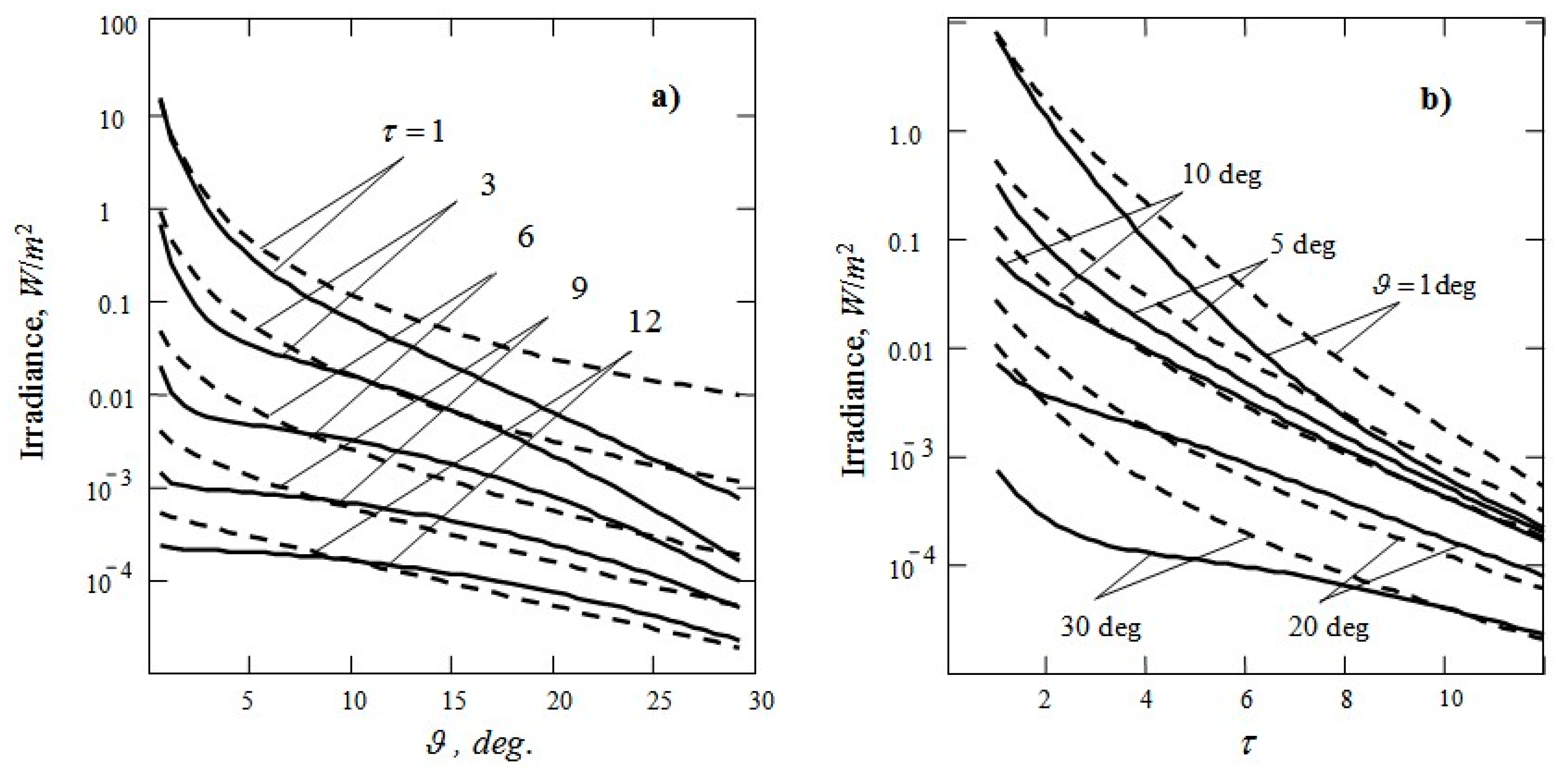
The results of calculating the field E ( U P S ) ( r , ϑ ) by the above formulas are shown in Figure 2 solid curves. The dashed curves depict the irradiance distribution calculated in the small-angle approximation by the formula
E S A ( U P S ) ( r , ϑ ) = exp ( c r ) 2 π r 2 0 exp [ b 1 r 2 n = 1 2 p n γ n 2 1 + γ n 2 ν 2 ] J 0 ( ϑ ν ) ν d ν
This formula neglects the photon path dispersion effects but it well describe the irradiance distribution near the axis of a stationary light beam at moderate optical distances from the source ( τ = c r < 8 ÷ 12 ), which is confirmed by field experiments and the results of Monte Carlo modeling the structure of a light beam in water [5,39]. As the figure shows, the new model of BSF underestimates the irradiation if ( 3 ÷ 5 ) < τ < 12 , ϑ < 10 ÷ 15 deg. However, this model should more accurately describe the irradiance distribution far from the beam axis. The new model, unlike formula (64), correctly describes the evolution of the beam structure at very large distances from the source, where the stationary angular distribution of irradiance F ( ϑ ) is formed and BSF takes the form E ( U P S ) ( r , ϑ ) F ( ϑ ) exp ( α r ) (see Equations (48), (56), and (57)).
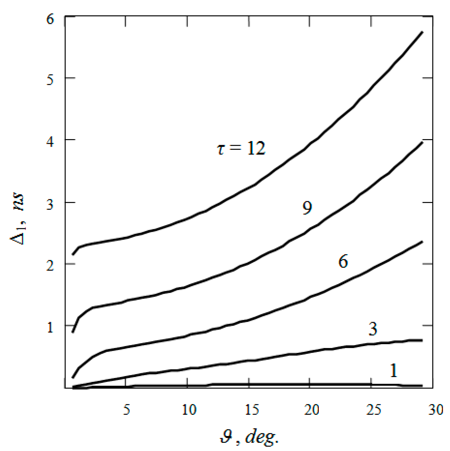
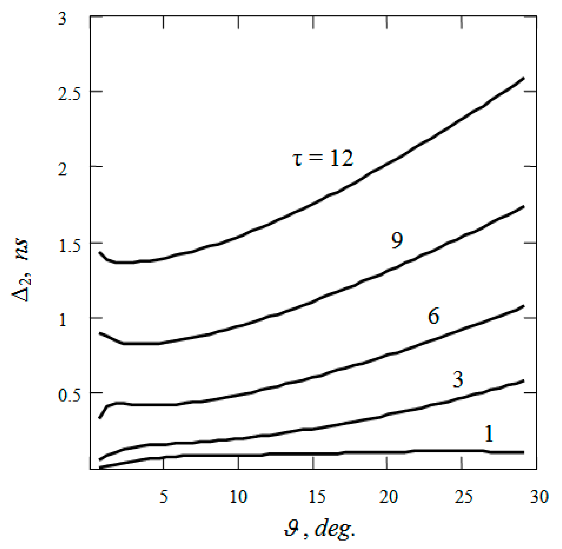
But the main advantages of the new model should be manifested in the study of the influence of the aquatic environment on the characteristics of non-stationary light fields. As an example in Figure 3 and Figure 4 show the results of calculating the integral parameters ( Δ 1 , Δ 2 ) of a light signal coming from the δ -pulse UPS to a given point in water from the solid angle 4 π . The calculations were made by Equation (11) and model of the field E ( U P S ) . Note that if we substitute the function E S A ( U P S ) in Equation (11) instead of the function E ( U P S ) , then we get Δ 1 = Δ 2 = 0 , since Equation (64) does not take into account the photon path dispersion effects.
A comparative analysis of the considered BSF models shows that it is advisable to use formula (64) to calculate the irradiation distribution in a stationary light beam at optical distances from the source τ < 12 . It can also be used to estimate the energy of a signal from a pulsed UPS. The calculation of the characteristics of a modulated light beam for arbitrary values of τ and the irradiation distribution in a stationary beam at optical distances τ > 12 should be carried out using new formulas. Note that according to preliminary estimates, the accuracy of calculating the frequency characteristics of a modulated light beam at distances τ < 12 can be increased if, instead of formula (8), one uses the equation
E ˜ s ( U P S ) ( r , ϑ , ω ) = P s ( ω ) [ E S A ( U P S ) ( r , ϑ ) / E ( U P S ) ( r , ϑ , a ) ] E ( U P S ) ( r , ϑ , a + i ω / c w )
A more detailed verification of the quality of new BSF model will require a special study.

5. Conclusions

A technique for calculating the irradiance distribution E ( U P S ) from a point unidirectional source (UPS) in turbid media with a narrow scattering phase function, which include sea water, is presented. Using the optical reciprocity theorem, the problem is reduced to finding the radiation field L ( O P S ) of an omnidirectional point source (OPS). A new analytical model of this field is developed, which is based on the solution of the radiative transfer equation (RTE) “in the refined small-angle approximation”. The field is represented as the sum of the first three terms of its expansion in scattering multiplicity powers and multiple scattered component. The first three terms were calculated using an RTE with an integral term, while to find the last term, we used an RTE “in the refined small-angle diffusion approximation.” A previously unknown solution of nonlinear Equation (50) with the boundary condition was found, because of which it was possible to obtain a compact expression for the multiple scattered component of the field L ( O P S ) . To calculate the characteristics of modulated light fields, it is proposed to use a well-known method based on the similarity of equations for the stationary radiation field and harmonic component of the nonstationary field. A comparative analysis of the results of calculating the spatial structure of a stationary light beam using new formulas and a well-known formula, which neglects the effects of multipath propagation of light, was performed. The possibilities of employing the results of the paper to study nonstationary light fields was illustrated by calculating the temporal characteristics of a δ -pulsed light beam. Considerations have been expressed for sharing the new BSF model and formulas of small-angle approximation for calculating the characteristics of light fields in the sea.

Funding

This research was funded by Russian Foundation for Basic Research (grants 19-02-00089 and 18-45-520011).

Acknowledgments

The author is grateful to A.G. Luchinin, O.V. Kopelevich, A. A. Mol’kov, and E.A. Sergeeva for useful discussions.

Conflicts of Interest

The authors declare no conflict of interest.

References

  1. Jaffe, J.S.; Moore, K.D.; McLean, J.; Strand, M.P. Underwater optical imaging: Status and prospects. Oceanography 2001, 14, 64–75. [Google Scholar] [CrossRef] [Green Version]
  2. Levin, I.M. Observation of objects illuminated by a narrow light beam in a scattering medium. Izvestiya Acad. Sci. USSR Atmos. Ocean. Phys. 1969, 5, 62–76. [Google Scholar]
  3. Bravo-Zhivotovsky, D.M.; Dolin, L.S.; Luchinin, A.G.; Savel’ev, V.A. Some problems of the theory of visibility in turbid media. Izvestiya Acad. Sci. USSR Atmos. Ocean. Phys. 1969, 5, 388–393. [Google Scholar]
  4. Mertens, L.E.; Replogle, F.S. Use of point spread and beam spread function for analysis of imaging systems in water. J. Opt. Soc. Am. 1977, 67, 1105–1117. [Google Scholar] [CrossRef]
  5. Dolin, L.S.; Levin, I.M. Theory of Underwater Vision; Hydrometeoizdat: Leningrad, Russia, 1991; p. 230. [Google Scholar]
  6. Zege, E.P.; Ivanov, A.P.; Katsev, I.L. Image Transfer through a Scattering Medium; Springer: Berlin/Heidelberg, Germany, 1991; p. 349. [Google Scholar]
  7. Luchinin, A.G.; Dolin, L.S. Model of an underwater imaging system with a complexly modulated illumination beam. Izvestiya Atmos. Ocean. Phys. 2014, 50, 411–419. [Google Scholar] [CrossRef]
  8. Dolin, L.S.; Savel’ev, V.A. Characteristics of back scattering signal at pulse radiation of turbid medium by a narrow directional light beam. Izvestiya Acad. Sci. USSR Atmos. Ocean. Phys. 1971, 7, 505–510. [Google Scholar]
  9. Billard, B.; Abbot, R.H.; Penny, M.F. Airborne estimation of sea turbidity parameters from the WRELADS laser airborne depth sounder. Appl. Opt. 1986, 25, 2080–2088. [Google Scholar] [CrossRef]
  10. Hoge, F.E.; Wright, C.W.; Krabill, W.B.; Buntzen, R.R.; Gilbert, G.D.; Swift, R.N.; Yungel, J.K.; Berry, R.E. Airborne lidar detection of subsurface oceanic scattering layers. Appl. Opt. 1988, 27, 3969–3977. [Google Scholar] [CrossRef]
  11. Measures, R.M. Laser Remote Sensing: Fundamentals and Applications; Krieger: Malabar, FL, USA, 1992; p. 524. [Google Scholar]
  12. Walker, R.E. Marine Light Statistics; Wiley: New York, NY, USA, 1994; p. 675. [Google Scholar]
  13. Bunkin, A.F.; Vlasov, D.V.; Mirkamilov, D.M.; SLOBODIANIN, V. Laser airborne remote sensing of turbidity profiles and mapping of phytoplankton distribution. Akademiya Nauk SSSR Doklady 1984, 277, 335–337. [Google Scholar]
  14. Vasilkov, A.P.; Goldin, Y.A.; Gureev, B.A.; Hoge, F.E.; Swift, R.N.; Wright, C.W. Airborne polarized lidar detection of scattering layers in the ocean. Appl. Opt. 2001, 40, 4353–4364. [Google Scholar] [CrossRef]
  15. Feygels, V.I.; Kopilevich, Y.I.; Surkov, A.I.; Yungel, J.K.; Behrenfeld, M.J. Airborne lidar system with variable field-of-view receiver for water optical measurements. Proc. SPIE 2003, 5155, 12–21. [Google Scholar]
  16. Churnside, J.H.; Ostrovsky, L.A. Lidar observation of a strongly nonlinear internal wave train in the Gulf of Alaska. Int. J. Remote Sens. 2005, 26, 167–177. [Google Scholar] [CrossRef]
  17. Kopilevich, Y.I.; Feygels, V.I.; Tuell, G.H.; Surkov, A. Measurement of ocean water optical properties and seafloor reflectance with scanning hydrographic operational airborne lidar survey (SHOALS): I. Theoretical background. Proc. SPIE 2005, 5885, 106–114. [Google Scholar]
  18. Tuell, G.H.; Feygels, V.; Kopilevich, Y.; Weidemann, A.D.; Cunningham, A.G.; Mani, R.; Podoba, V.; Ramnath, V.; Park, J.Y.; Aitken, J. Measurement of ocean water optical properties and seafloor reflectance with scanning hydrographic operational airborne lidar survey (SHOALS): II. Practical results and comparison with independent data. Proc. SPIE 2005, 5885, 115–127. [Google Scholar]
  19. Luchinin, A.G. Theory of underwater lidar with a complex modulated illumination beam, Izvestiya. Atmos. Ocean. Phys. 2012, 48, 663–671. [Google Scholar] [CrossRef]
  20. Dolin, L.S. Light beam scattering in a turbid medium layer. Izvestiya Vysshikh Uchebnykh Zavedenii, Radiofizika. 1964, 7, 471–478. [Google Scholar]
  21. Dolin, L.S. Propagation of a narrow beam of light in a medium with strongly anisotropic scattering. Izvestiya Vysshikh Uchebnykh Zavedenii, Radiofizika. 1966, 9, 40–47. [Google Scholar] [CrossRef]
  22. Bravo-Zhivotovsky, D.M.; Dolin, L.S.; Luchinin, A.G.; Savel’ev, V.A. Structure of a narrow light beam in sea water. Izvestiya Acad. Sci. USSR Atmos. Oceanic Phys. 1969, 5, 160–167. [Google Scholar]
  23. Arnush, D. Underwater light-beam propagation in the small-angle approximation. J. Opt. Soc. Am. 1972, 62, 1109–1111. [Google Scholar] [CrossRef]
  24. Ishimaru, A. Wave Propagation and Scattering in Random Media; Academic Press: New York, NY, USA, 1978; p. 272. [Google Scholar]
  25. Dolin, L.S.; Savel’ev, V.A. Theory of the propagation of a narrow light beam in a stratified scattering medium. Izvestiya Vysshikh Uchebnykh Zavedenii, Radiofizika. 1979, 22, 911–917. [Google Scholar] [CrossRef]
  26. Furutsu, K. An analytical theory of pulse wave propagation in turbulent media. J. Math. Phys. 1979, 20, 617–628. [Google Scholar] [CrossRef]
  27. Ishimaru, A. Pulse propagation, scattering, and diffusion in scatterers and turbulence. Radio Sci. 1979, 14, 269–276. [Google Scholar] [CrossRef]
  28. Dolin, L.S. Solution of the radiation transfer equation in a small-angle approximation for a stratified turbid medium with photon path dispersion taken into account. Izvestiya Acad. Sci. USSR Atmos. Ocean. Phys. 1980, 16, 55–64. [Google Scholar]
  29. Hulst, H.C.; Kattawar, G. Exact spread function for pulsed collimated beam in a medium with small-angle scattering. Appl. Opt. 1994, 33, 5820–5829. [Google Scholar] [CrossRef]
  30. Luchinin, A.G.; Savel’ev, V.A. Propagation of a sinusoidally modulated light beam through a scattering medium. Izvestiya Vysshikh Uchebnykh Zavedenii, Radiofizika. 1969, 12, 256–264. [Google Scholar] [CrossRef]
  31. Rogozkin, D.B. Propagation of light pulse in a medium with strongly anisotropic scattering. Izvestiya Acad. Sci. USSR Atmos. Ocean. Phys. 1987, 23, 275–281. [Google Scholar]
  32. Dolin, L.S. Self-similar approximation in the theory of the strongly anisotropic multiple scattering of light. Doklady 1981, 1344–1347. [Google Scholar]
  33. Dolin, L.S. Passage of a pulsed light signal through an absorbing medium with strongly anisotropic scattering. Izvestiya Vysshikh Uchebnykh Zavedenii, Radiofizika. 1983, 26, 220–228. [Google Scholar] [CrossRef]
  34. McLean, J.W.; Freeman, J.D.; Walker, R.E. Beam spread function with time dispersion. Appl. Opt. 1998, 37, 4701–4711. [Google Scholar] [CrossRef]
  35. Case, K.M.; Zweifel, P.F. Linear Transport Theory; Addison-Wesley: London, UK, 1967; p. 342. [Google Scholar]
  36. Sergeeva, E.A.; Kirillin, M.Y.; Priezzhaev, A.V. Propagation of a femtosecond pulse in a scattering medium: Theoretical analysis and numerical simulation. Quantum Electron. 2006, 36, 1023–1031. [Google Scholar] [CrossRef]
  37. Zege, E.P.; Katsev, I.L.; Prikhach, A.S.; Gilbert, G.; Witherspoon, N. Simple model of the optical characteristics of bubbles and sediments in seawater of the surf zone. Appl. Opt. 2006, 45, 6577–6585. [Google Scholar] [CrossRef] [PubMed]
  38. Levin, I.M.; Kopelevich, O.V. Correlations between the inherent hydrooptical characteristics in the spectral range close to 550 nm. Oceanology 2007, 47, 344–349. [Google Scholar] [CrossRef]
  39. Dolin, L.S.; Savel’ev, V.A. New model for the light-beam spread function in a medium with strongly anistropic scattering. Izvestiya Atmos. Ocean. Phys. 2000, 36, 730–736. [Google Scholar]
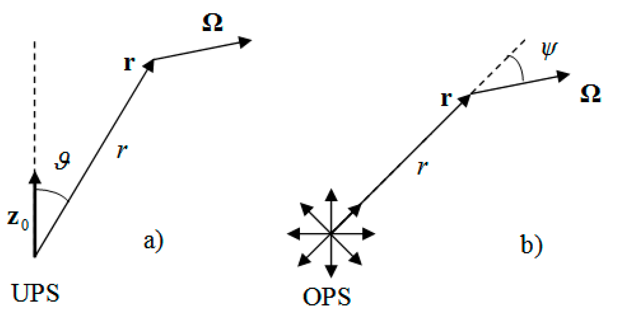
Figure 1. Schematic representation for the unidirectional (a) and omnidirectional (b) light point sources.
Jmse 08 00079 g001
Figure 2. Irradiance from unidirectional point source (UPS) depending on the polar angle (a) and optical distance (b), calculated according to new formulas (solid curves) and to Equation (64) (dotted curves); the numbers in (a,b) indicate the values of τ and ϑ , respectively; source power 1 W, c = 0.4 m−1.
Jmse 08 00079 g002
Figure 3. The delay of the “center of gravity” of the pulse Δ 1 = t ¯ ( r / c w ) (in nanoseconds) because of the scattering of light in water depending on the angle ϑ at various optical distances τ (indicated by the numbers in the figure); c = 0.4 m−1.
Jmse 08 00079 g003
Figure 4. The pulse broadening (in nanoseconds) because of the scattering of light in water depending on the angle ϑ at various optical distances τ (indicated by numbers in the figure); c = 0.4 m−1.
Jmse 08 00079 g004