Article

Thermal Stress Analysis of Process Piping System Installed on LNG Vessel Subject to Hull Design Loads

1
Research Institute of Industrial Technology, INHA University, 100 Inha-ro, Michuhol-gu, Incheon 22212, Korea
2
Department of Naval Architecture and Ocean Engineering, INHA University, 100 Inha-ro, Michuhol-gu, Incheon 22212, Korea
*
Author to whom correspondence should be addressed.
J. Mar. Sci. Eng. 2020, 8(11), 926; https://doi.org/10.3390/jmse8110926
Submission received: 15 October 2020 / Revised: 9 November 2020 / Accepted: 13 November 2020 / Published: 16 November 2020
(This article belongs to the Special Issue Smart Technologies for Shipbuilding)

Abstract

:
In this paper, the procedure for the strength evaluation of the piping system installed on liquefied natural gas (LNG) carriers is discussed. A procedure that accounts for the ship’s wave load and hull motion acceleration (as well as the deformation due to the thermal expansion and contraction experienced by the hull during seafaring operations) is presented. The load due to the temperature and self-weight of the piping installed on the deck is also considered. Various operating and load conditions of the LNG piping system are analyzed. Stress analysis is performed by combining various conditions of sustained, occasional, and expansion loads. Stress is assessed using finite element analysis based on beam elements that represent the behavior of the piping. The attributes of the piping system components (such as valves, expansion joints, and supports) are represented in the finite element model while CAESAR-II, a commercial software is used for finite element analysis. Component modeling, load assignment, and load combinations are presented to evaluate pipe stresses under various load conditions. An evaluation model is selected for the piping arrangement of LNG and the evaluated stress is compared with the allowable stress defined by the American Society of Mechanical Engineers (ASME).

1. Introduction

Liquefied natural gas (LNG) piping systems are equipped with process equipment such as pressure vessels, pumps, heat exchangers, supports, and regasification facilities to store and transport natural gas in a liquid state. These piping systems are intricately connected to the various parts that make up the piping such as the support, the flange, the expansion joint, and the process equipment [1]. These parts are exposed to external forces generated by several operation conditions such as contraction load, pipe pressure, and deadweight [2,3,4]. This study proposes a method for assessing the structural safety of process pipes installed on the deck of LNG carriers [5]. LNG cargo containments and pipe networks receive, store, and process natural gas. LNG cargo containments and insulation panels are the core equipment for LNG carriers. Currently, research related to the design technology of LNG cargo tanks has been presented in various ways [6,7]. However, studies on the structural safety assessment of pipe systems on LNG carriers have not yet been generalized.
The pipeline of the LNG carriers differs from general oil and gas pipelines in that the pipeline is not only subject to the risk of thermal stress due to temperature distribution, but also experiences stress due to hull motion and hull deformation. Shrinkage, tensile, and inertial forces due to ship motion can cause serious structural damage to pipelines and equipment, potentially leading to leaks and accidents. Therefore, the safety requirements of pipelines on LNG carriers are higher than those of other types of oil and gas facilities. Attempts to analyze the stress in the oil gas process piping system can be found in many studies, as described below. The piping systems of oil and gas plants also experience stresses due to the self-weight of the pipe, internal pressure, thermal load, wind load, and seismic load. These stresses must be under the allowable stress specified by the American Society of Mechanical Engineers (ASME) B31.1 [4,8,9]. Lu et al. [10] presented constraints on a positive displacement pump pipeline system and a mechanical model of the pipeline based on stress and vibration analysis. Numerical simulations (including stress and vibration analyses) were performed for an oil transportation station. Miranda and López introduced the design process for a steam pipe by subdividing it into major categories such as design criteria, process flow diagram, separator location, pipe route, pipe specification, pressure design, load design, design code, and piping stress analysis [11]. Sharma et al. [9] and Shang et al. [12] also discussed finite element analysis procedures that account for the bending geometry and loading conditions of process piping systems. Sohail et al. [13] performed an analysis to add heat exchangers to process piping according to the standard code for process piping.
The displacement, stress, reaction, and nozzle analysis results of the piping system according to the selection and location of the pipe supports were calculated using CAESAR-II software [14]. Wu et al. [15] conducted a stress analysis on oil and gas pipes through the tunnel, considering the differences in terrain obstacles. Based on the finite element method, the stresses and displacements of parallel pipes and gas pipes were analyzed using CAESAR-II software. With regard to the stress analysis of LNG pipelines, Brown et al. [16] used a finite element model to analyze the displacement and stress of subsea LNG pipelines. Wang et al. [5] analyzed the cargo handling pipeline of LNG carriers using CAESAR-II software. They presented the feasibility of setting the horizontal expansion joint and outlined the principles for setting the piping support. Yu et al. [2] proposed the optimization of the piping system using a spring hanger after the consideration of gravity, temperature, pressure, wind, and seismic load. They also proposed a method to obtain the allowable stress in the case of accidental load.
The stresses in piping systems of LNG carriers and offshore structures are influenced not only by self-weight, pressure load, and thermal load, but also by hull bending moment, reaction force by support, forced displacement by thermal deformation of hull structure, and inertial force caused by hull motion acceleration [1,17]. The design of the LNG pipeline requires the consideration of various factors defined by codes and classification regulations by Det Norske Veritas and Germanischer Lloyd (DNV GL) [18] and ASME B31.1 [4]. However, the regulation does not specify the load generated by the wave-induced bending moment of a ship and the thermal deformation of the hull structure.
Since methods should be developed for evaluating the stress of pipelines accounting for the deformation behavior of ships and offshore structures, this study focuses on developing a piping stress assessment procedure that represents the load characteristics of LNG carriers. The most important concern in the pipe stress evaluation is how to represent the environmental factors that differ from general oil and gas plants. This study proposes a procedure to evaluate the structural safety of LNG carrier piping systems with the consideration of the operation environment of LNG vessels. The stress assessment procedure is applied to multiple scenarios with various combinations of loads defined by DNV GL [18].

2. Load and Stress of the Piping System

This section discusses the types of loads and the load combinations acting on the LNG piping system. The allowable stresses on the piping are summarized using load types defined by the ASME regulations. Moreover, the stress intensification factor (SIF) is calculated according to the shape of the curved pipe.
Sustained, occasional, and secondary load conditions suggested by ASME regulations were reflected in a combination of load boundary conditions to analyze the piping stress by reflecting the characteristics of valves, expansion joints and flanges in the LNG carrier piping system. Each load condition and load combination reflected was organized in accordance with ASME Code criteria and reflected each procedure for evaluating stress as follows.

2.1. Categorization of Pipe Stresses

Loads acting on the LNG piping system include self-weight, pressure, temperature, restraint force at piping support due to hull bending, forced displacement due to hull thermal deformation, and inertia forces of wave-induced ship motion. The stress due to the pressure in the pipe is evaluated using the longitudinal stress and the hoop stress of the cylindrical pressure vessel. The loads (except for the internal pressure) are represented by the equivalent longitudinal axial force and equivalent bending moment. ASME B31.1 [4] defines the total stress from the stress components of the cylindrical pressure and the stress components of the beam bending.

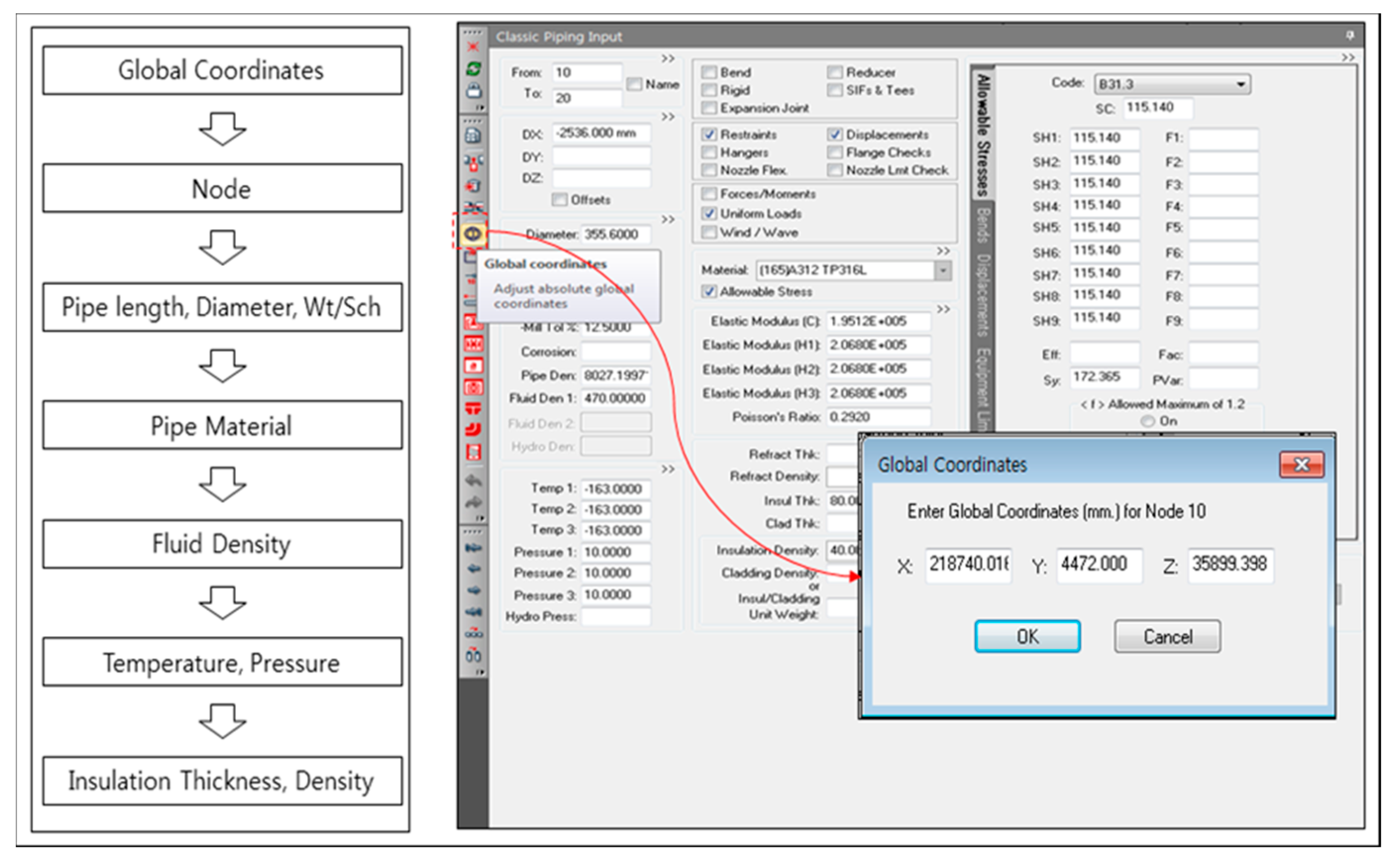
2.2. Minimum Thickness of Pipe

The minimum thickness of the pipe is determined by the magnitude of the internal pressure and is calculated in Equation (1) [4]. In the case of corrosion due to inner fluid, a corrosion margin of at least 1 mm is added to the minimum thickness.
t m = P × D 2 ( S × E × W + P × γ ) + A
where:
  • t m = Minimum pipe wall thickness required (m);
  • P = Internal design pressure (MPa);
  • D = Outside diameter of pipe (mm);
  • A = Corrosion and wear erosion allowance (mm);
  • S = Allowable stress due to pressure and joint efficiency at the design temperature (MPa);
  • E   ≤ 1, Quality Factors [3];
  • W = Weld joint strength reduction factor;
  • γ = Temperature correction factor from ASME B31.1 Table 104.1.2 [4].

2.3. Loads to be Consider in the LNG Pipe System

After determining the minimum thickness of the pipe, the stress was evaluated according to the ANSI B31.1 code. The maximum stress for each combination of load conditions should be evaluated. If the maximum stress of a load combination does not meet the allowable stress limit, the pipe dimensions or the arrangement of the piping system components should be modified. The piping loads are classified into three types as follows:
  • (a) Sustained loads and stresses (primary loads and stress)
Sustained loads acting throughout the operation are the sum of deadweight loads, axial loads caused by internal pressure, and other applied axial loads that are not caused by temperature and accelerations, etc. Deadweight refers to the weight of the pipe and associated components (such as flanges, valves, and strainers mounted on the piping system, the weight of fluid/contents in the piping, and the weight of insulation). Primary stress or sustained stress ( S L ) is generated by sustained loads. Sustained stress is mainly caused by the pressure of the fluid. It occurs due to the internal and external forces and moments of sustained loads like deadweight, self-weight, and bending moments. The piping codes keep the primary stresses below the yield point by a safety factor, as shown in Equation (2). S L is the superposition of longitudinal membrane stress ( P L ) and the weight-bending stress ( Q b ).
S L = P L + Q b = P × D ( 1000 ) × 4 t m + 0.75 i M A Z 1.0 S h
where P , D , and t are the pressure (MPa) in the pipe, the pipe outer diameter (mm), and the pipe thickness (mm), respectively. M A is the equivalent bending moment (N-mm) due to the weight and support load of the insulation, valve, and pump. Z is the section modulus of the pipe and i is the SIF. These comply with ASME B31.1 [4] Appendix D. S h denotes the allowable stress at the maximum operating temperature (values are listed in Appendix A of ASME B31.1 [4]).
  • (b) Occasional loads
Occasional loads act temporary during the operation and are combined with design pressure and weight. These loads include wind, seismic, breaking waves or green sea impact loads, dynamic loads such as pressure relief, or fluid surge loads. The ASME B31.3 [3] code has specific requirements for the accumulated hours of the occurrence of such loads. The allowable occasional stress limit is listed in Section 302.3.6 of ASME B31.3 [3]. Normal operating temperature is used in the assessment of occasional loads. Stresses due to occasional loads are the algebraic summations of longitudinal sustained weight stress, longitudinal pressure stress, and occasional stress. They shall satisfy the stress equation specified in ASME B31.1. [4]—Equation (3)—which is given below:
S 0 = P × D ( 1000 ) 4 t m + 0.75 i M A Z + 0.75 i M B Z K S h
where:
  • K = 1.15 for occasional loads acting less than 10% of operating period;
  • K = 1.20 for occasional loads acting less than 1% of operating period.
where M A is the equivalent bending moment due to the sustained load and M B is the equivalent bending moment due to the occasional load. K is the factor value determined by the duration time of the occasional load. Equation (3) shows that the longitudinal stress due to occasional loads is less than or equal to K   S h (ASME B31.1 Appendix 102.2.4 [4]). S h is the basic material allowable stress at maximum (hot) temperature.
  • (c) Thermal expansion loads and stress (secondary loads and stress)
Thermal expansion and contraction occurs when a pipe heats up and cools down. The piping system must have enough flexibility to handle the thermal expansion and contraction. Secondary loads are driven by the thermal expansion of both the pipes and hull structure, anchors, and restraints, as they are related to the continuity of the piping system. Secondary expansion stress ( S E ) is generated by the thermal load and forced displacement caused by temperature difference and thermal deformation of the hull and bending (sagging and hogging). In this study, forced displacement load transferred from hull expansion and contraction is added to the thermal expansion loads, along with the consideration of the wave bending moment and the thermal expansion of the deck. The secondary stress ( S E ) should not exceed the allowable stress ( S A ), as shown in Equation (4).
S E = S b 2 + 4 S t 2 < S A
where S b and S t are the resultant bending stress (MPa) and torsional stress (MPa) caused by thermal load and deformation, respectively. Resultant bending stress ( S b ) is generated by temperature, the deadweight of the pipe, and the weight of insulation, as defined in Equation (5). The torsional stress ( S t ) due to the moment ( M t ) is given by Equation (6).
S b = ( M i × i i ) 2 + ( M o × i o ) 2 Z
S t = M t 2 Z
where M i , M o , M t are the inner and outer plane bending moments (N-mm), and the torsional moment, as shown in Figure 1. i i , i o are the inner and outer plane stress intensification factors, respectively [19]. The allowable stress ( S A ) is defined by Equation (7). S A is calculated with Equation (8) if S L is less than or equal to S h . f is the stress range factor (accounting for the fatigue load) and is determined by the number of cyclic loads N [17]. A default value of f = 1.0 is applied here. However, if N is greater than 7000, the value of f specified in Table 1023.2 (C) of ASME B31.1 [4] is used in Equations (7) and (8).
S A = f [ 1.25 S c + 0.25 S h ]
S A = f [ 1.25 ( S c + S h ) S L ]
where:
  • S C = Material allowable stress at minimum (cold) temperature expected during the displacement cycle under analysis (MPa) (ASME Table K-1);
  • S h = Material allowable stress at maximum metal temperature expected during the displacement cycle under analysis (MPa) (ASME Table K-1);
  • f = Stress range factor.

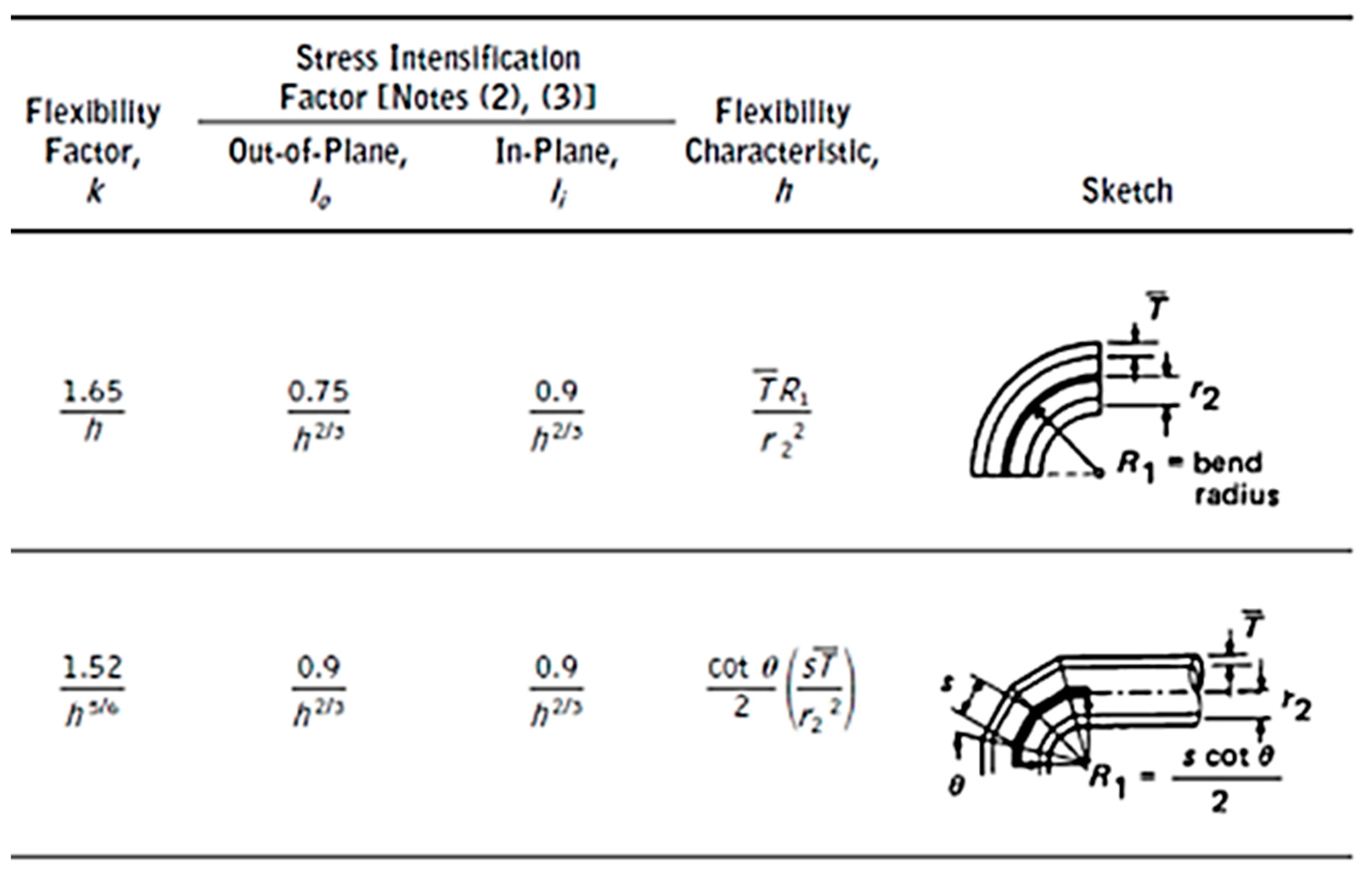
2.4. Stress Intensification Factor (SIF) and Flexibility Factor

The behavior of the straight pipe differs from that of the curved pipe under an externally applied bending moment. The straight pipe acts like a beam while retaining a circular cross section. In contrast, the cross section of the curved pipe becomes oval-shaped (see Figure 2). SIF is equivalent to the ratio of the maximum bending stress occurring in a straight pipe to that in a curved pipe, subject to bending moment. The bending stress S b in a straight pipe is calculated as S b = M / Z . The bending stress in a curved pipe is calculated as S b ¯ = M / Z , where Z denotes the reduced section modulus of the curved shape. The stresses in the curved pipe are higher compared to a straight pipe of the same size because of the reduced cross section modules. The SIF of the curved pipe is defined by S b ¯ / S b . Consider a straight pipe (refer Figure 1) with length l which will produce rotation θ under the action of bending moment M . A bend having same diameter and thickness with same arc length l under the action of same bending moment M will exhibit k θ rotation. k is called the flexibility factor. Figure 2 shows examples of SIFs and flexibility factors.

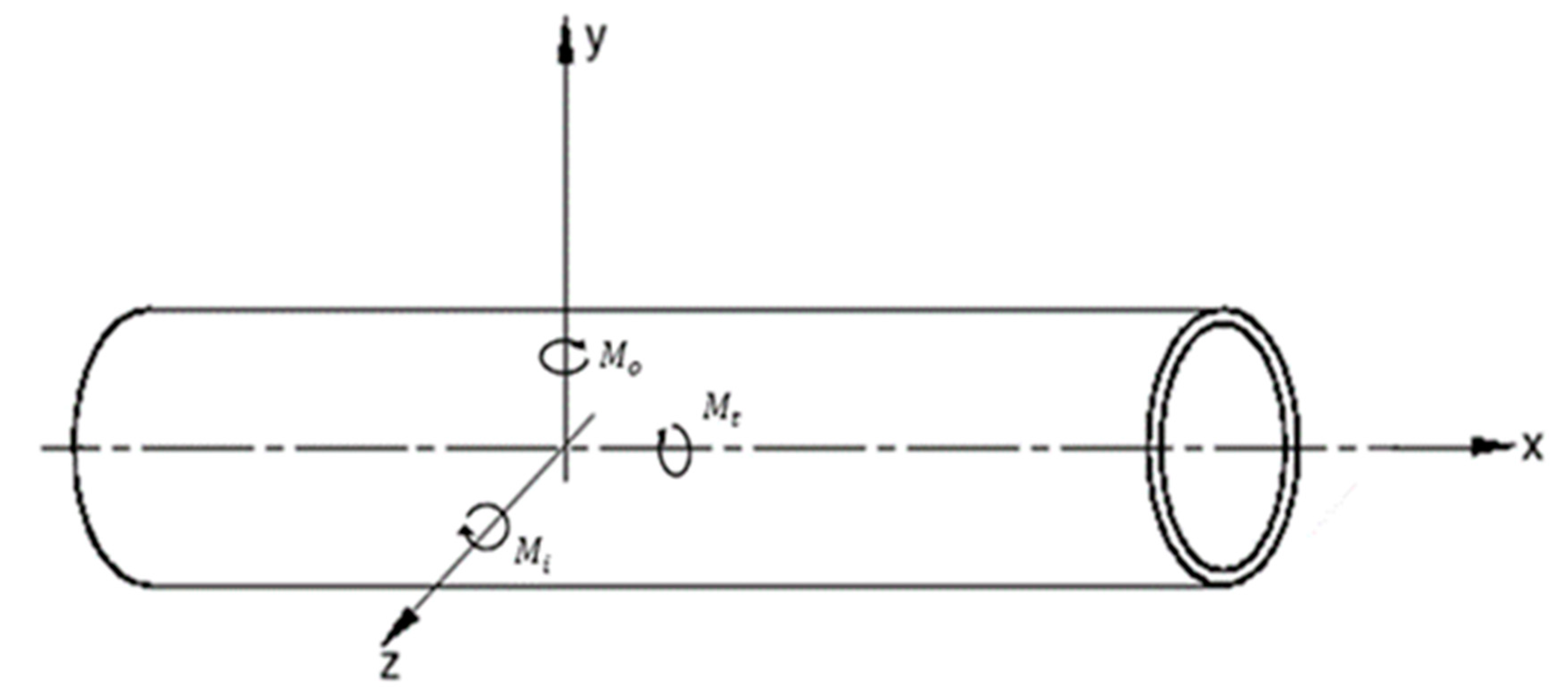
2.5. Bending Moment Generated by Thermal Expansion

The deadweight, thermal expansion, and forced displacement of the pipe are converted to the equivalent bending moment and the equivalent axial force to assign the load boundary condition on the pipe elements. This section summarizes both the equivalent bending moment and the equivalent axial force due to thermal expansion/contraction. The strain ε of the beam can be expressed as the sum of the elastic strain ε x e and the thermal strain ε x t h , as shown in Equation (9). In addition, because the strain of a pipe can be divided into an axial strain ( ε 0 ) and a bending strain ( κ y ), the in-plane and out-of-plane deformation ratios of the beam can be expressed by Equation (10). From Equations (9) and (10), the stress–strain relation of the beam can be obtained, as shown in Equation (11).
ε x = ε x e + ε x t h = σ x E + α T ( x , y )
ε x = ε 0 + k y
σ x E + α T ( x , y ) = ε 0 + κ y
where α , T ( x , y ) , and κ are the thermal expansion coefficient, temperature distribution, and curvature of beam, respectively. Integrating Equation (11) with respect to the cross section of the beam yields Equation (12). Consequently, the axial strain ( ε 0 ) and the equivalent axial load ( N T ) at the central axis due to thermal expansion can be defined by Equation (13). Integrating Equation (11) yields Equation (14); the equivalent bending moment ( M T ) can be obtained as shown in Equation (15).
A σ x E d A + A α T ( x , y ) d A = A ε 0 d y + A κ y d y
N T = A E α T ( x , y ) d A
A σ x E y d A + A α T ( x , y ) y d A = A ε 0 y d A + A κ y 2 d y
M T = A E α T ( x , y ) y d A

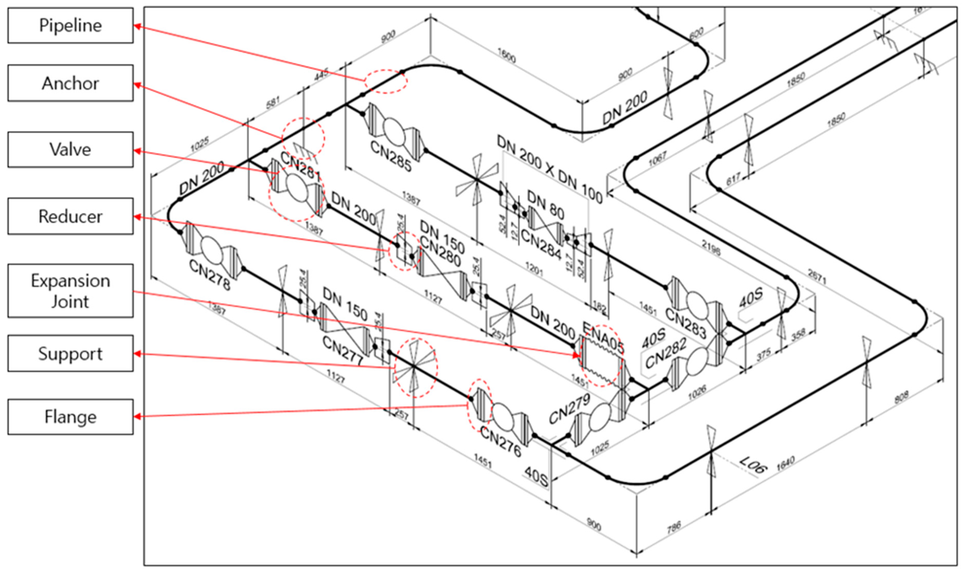
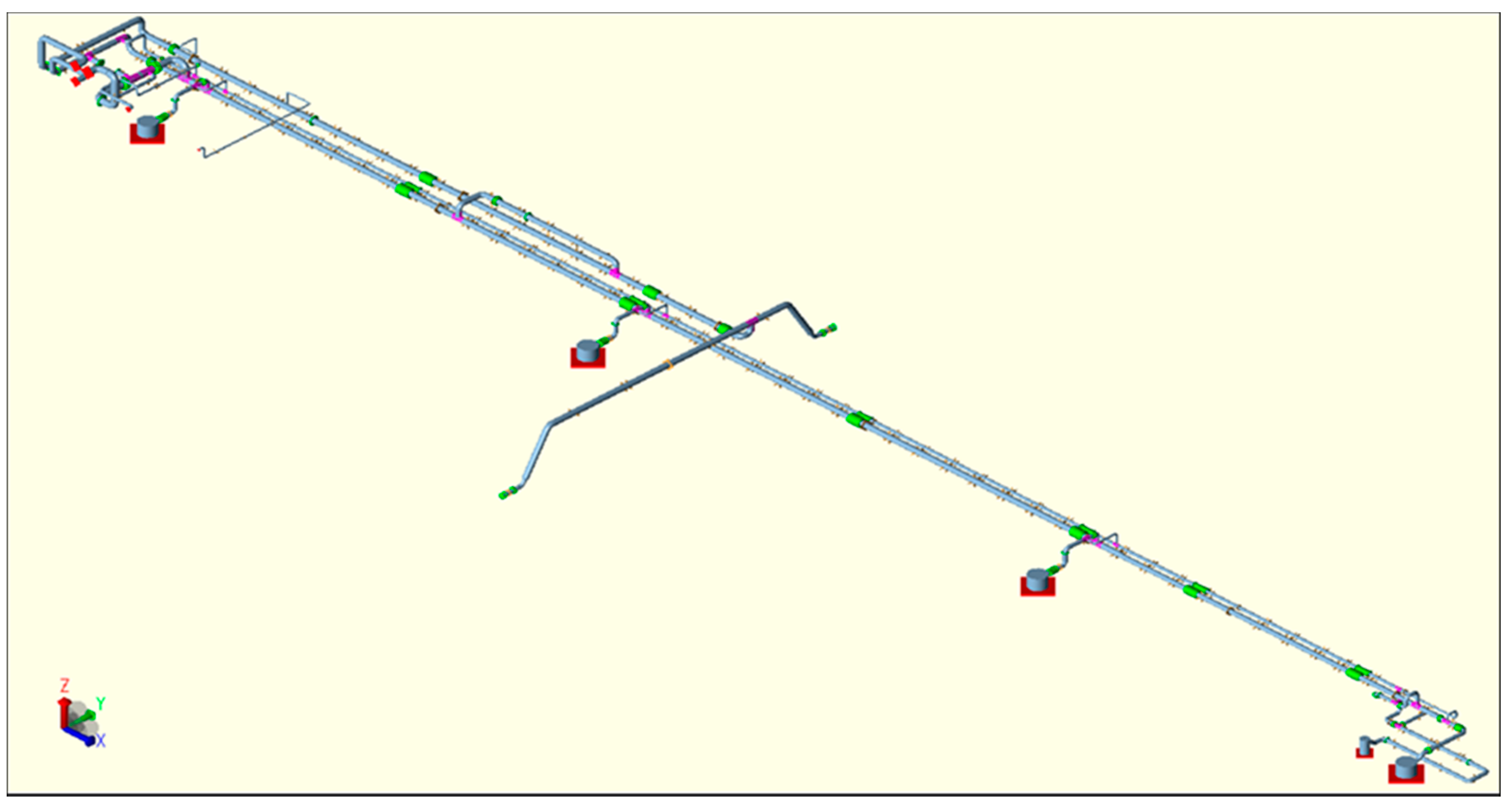
3. Components of Piping System

Piping stress analysis is a highly interactive design procedure to determine the arrangement of pipes, equipment, and supports. The layout design should be performed accounting for the piping support and stress so that the piping system has sufficient flexibility against thermal expansion and various loads. Therefore, piping stress analysis enables the determination of an optimal pipe system using various piping materials and cross-sectional properties (while considering pressure, temperature, and loads). The layout must be perfectly balanced between the stresses so that piping system arrangement efficiency is achieved [19,20].
Pipes, supports, valves, expansion joints, anchors, reducers, and flanges are all considered in the model (as shown in Figure 3). Butterfly valves, globe valves, and check valves are modeled by the valve element (which is supported by finite element) with properties such as valve type and connection type. The pressure class of the valve was determined according to the ASME B16.354 standard grade [21]. Since the piping stress depends on the position and number of supports and the suitability of expansion joints, the final objective of this study is to analyze the effect of the supports and expansion joints on stress. The coordinate axes for pipe modeling are defined as follows:
  • X axis: Longitudinal axis, positive forwards.
  • Y axis: Transverse axis, positive towards portside.
  • Z axis: Vertical axis, positive upwards.

3.1. Material Properties

The material properties are defined for the pipe, the insulation, and the fluid in the pipe. The material properties, including elastic modulus, Poisson ratio, and allowable stress, are summarized in Table 1. The material properties of the LNG piping are also summarized in Table 2. A gaseous line is used in the LNG piping system of DN 125 and above. The material properties of LNG or neutral gas (NG) are summarized in Table 3.

3.2. Loading Condition

For the analysis of thermal deformation, a default operating temperature should be defined. The default temperature is applied as the operating temperature defined in the Piping and Instrumentation Diagram (P&ID) drawings. Since the deformation also occurs due to the internal pressure of the pipe, the pressure of the pipe is input as the design pressure designated by the P&ID drawings.
  • (1) Acceleration load
The inertia force of all the members represented in the model is based on the acceleration formula of the IGC Code (Ch. 4.12) set by the International Maritime Organization [22]. Equations (16)–(20) denote the acceleration of the ship that is estimated by the functions of the principal dimensions of the ship. The accelerations also vary according to the position ( x ). The acceleration values applied in the analysis are summarized in Table 4.
Vertical acceleration:
a z = ± a 0 1 + ( 5.3 45 L 0 ) 2 ( x L 0 + 0.05 ) 2 ( 0.06 C B ) 1.5
Transverse acceleration:
a y = ± a 0 0.6 + 2.5 ( x L 0 + 0.05 ) 2 + K ( 1 + 0.6 K 2 B ) 2
Longitudinal acceleration:
a x = ± a 0 0.06 + A 2 + 0.25 A
where:
A = [ 0.7 L 0 1200 + 5 z L 0 ] [ 0.6 C B ]
a 0 = 0.2   V L 0 + 34 600 / L 0 L 0
  • L 0 = Length of ship for determination of scantlings (mm);
  • C B = Block coefficient;
  • B = Moulded breadth of the ship (mm);
  • K = 1 in general. For particular loading conditions and hull forms K = 13GM/ B ;
  • GM = The metacentric height (m);
  • x = Longitudinal distance (m) from amidships to the center of gravity of the LNG tank with contents ( x is positive forward of amidships, negative aft of amidships);
  • z = Vertical distance (m) from the ship’s actual waterline to the centre of gravity of LNG tank with contents;
  • ( z is positive above and negative below the waterline);
  • V = Service speed of ship (knots).
  • (2) Forced displacement of hull deformation
The topic of this study is the piping system installed on the deck of LNG carriers. Forced displacement due to hull bending and thermal deformation is applied at the constraints of pipes so that the secondary loads are assumed. The displacement is constrained at the support and the anchor. Therefore, the forced displacement boundary condition is given to these constrained locations. Table 5 summarizes the magnitude of the forced deformations due to hull bending and thermal expansion used in this study.
The bending deformation of the hull is divided into hogging and sagging, which means forced displacement in the longitudinal direction. Forced displacement can be assumed by using stress in the trunk deck and compression room. The displacement is obtained by multiplying the position ( x ) from the After-Perpendicular (AP) point of the ship and the strain applied as the forced deformation at the anchor or support point. Assuming that the hull is a beam, the strain is obtained by dividing the bending stress at the deck and the bottom of the ship by the elastic modulus, as shown in Equation (21). Forced displacement ( δ ) due to hull bending at the anchor or support point can be obtained as follows:
δ = ε × = σ E ×
Considering the position ( ) of the anchor and supporting points, deck thermal expansion ( δ t ) was calculated using Equation (22). The forced thermal deformation of the hull was considered in the same way as the longitudinal direction in the breadth direction. Positive (expansion) values were applied to the port side and negative (shrinkage) values were applied to the starboard side.
δ t = α × Δ T ×
where ε is the strain, σ is the deck stress, E is the elastic modulus, and l is the position of the constraint point. δ t is the thermal deformation, α is the thermal expansion coefficient, and Δ T is the temperature difference. The longitudinal thermal deformation and the transverse thermal deformation are calculated from the thermal expansion from the stern and the center of the hull, respectively.

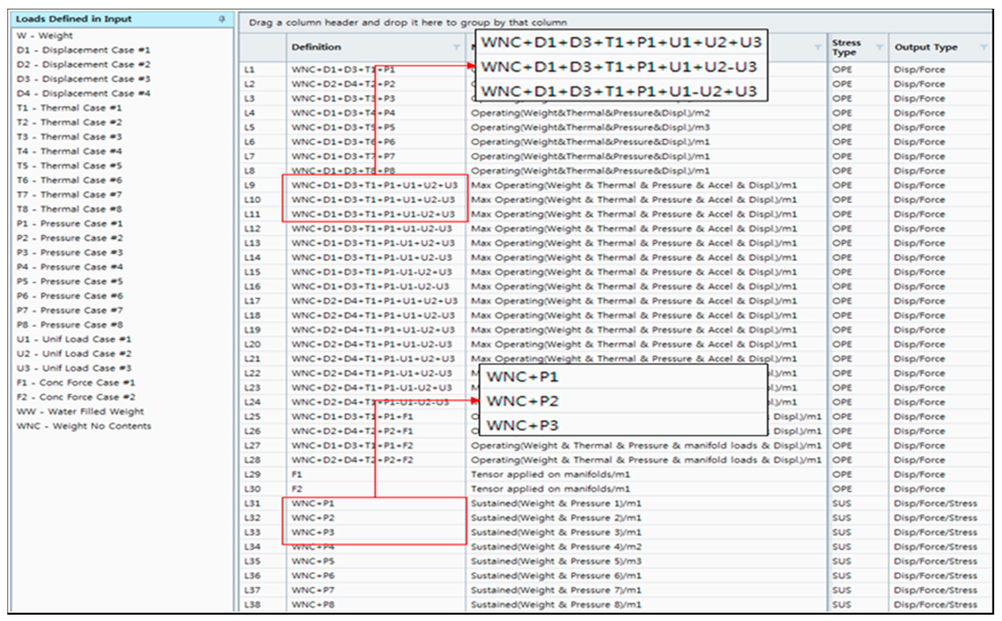
3.3. Load Cases: Combination of Loads

The main objectives of pipe stress analysis are to ensure the structural capacity against the pressure, various loadings in the life cycle, different operational scenarios, and loads on the supporting structures. To meet these objectives, several load cases were required during stress analysis. Load combination cases were translated to analysis scenarios defined in both Section 4.2 and ASME (2014) [4]. The load combination cases of this study are summarized in Table 6 and Table 7.

4. Stress Evaluation

General-purpose finite element analysis codes do not consider the geometric properties of supports, valves, and expansion joints. They also have difficulty in constructing analytical models for each load combination scenario [1,23]. Furthermore, it is difficult to evaluate the allowable stresses for each load case. CAESAR-Ⅱ was used in this study, which is a code for piping stress analysis.

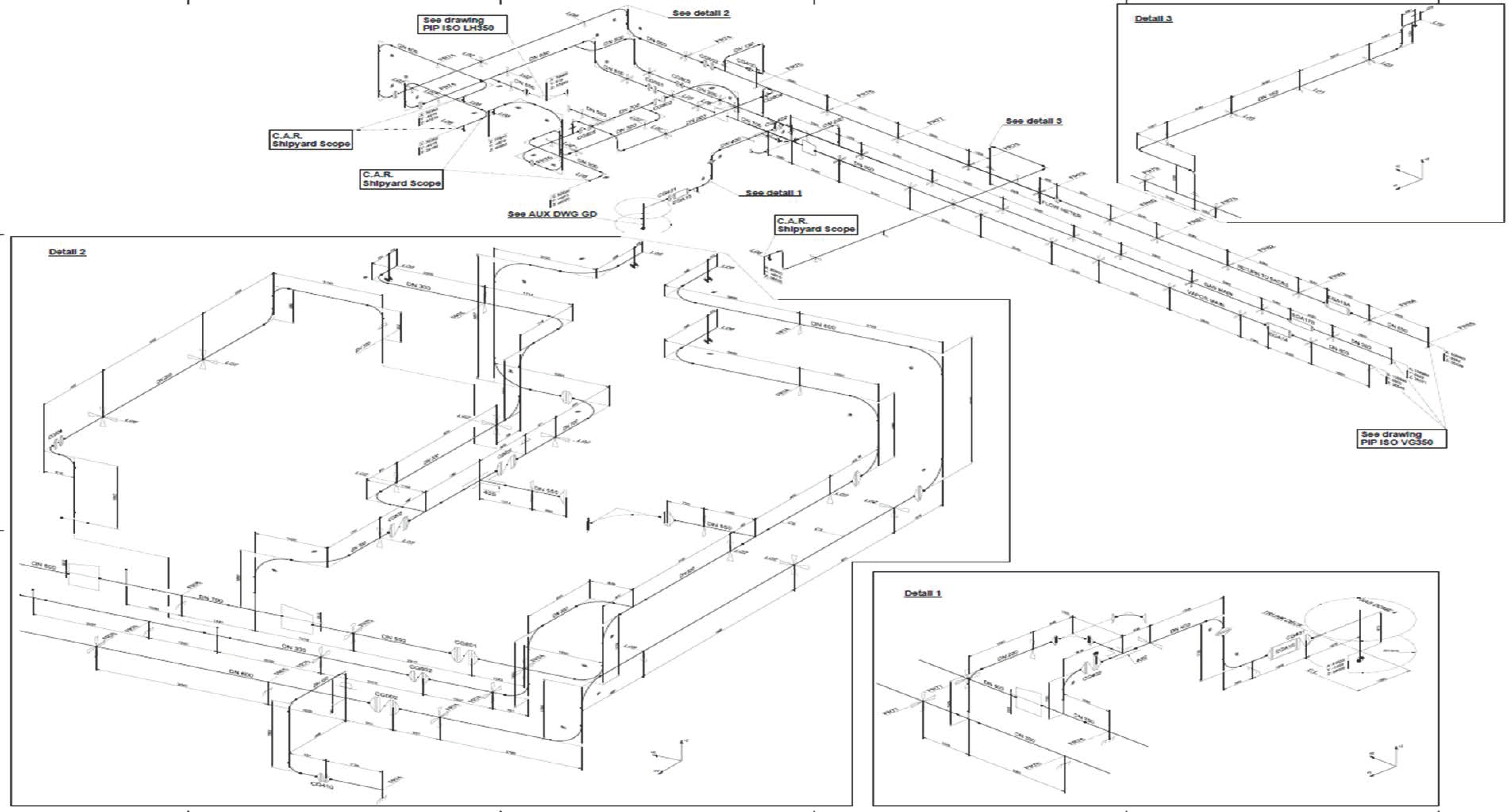
4.1. Geometry of Piping System
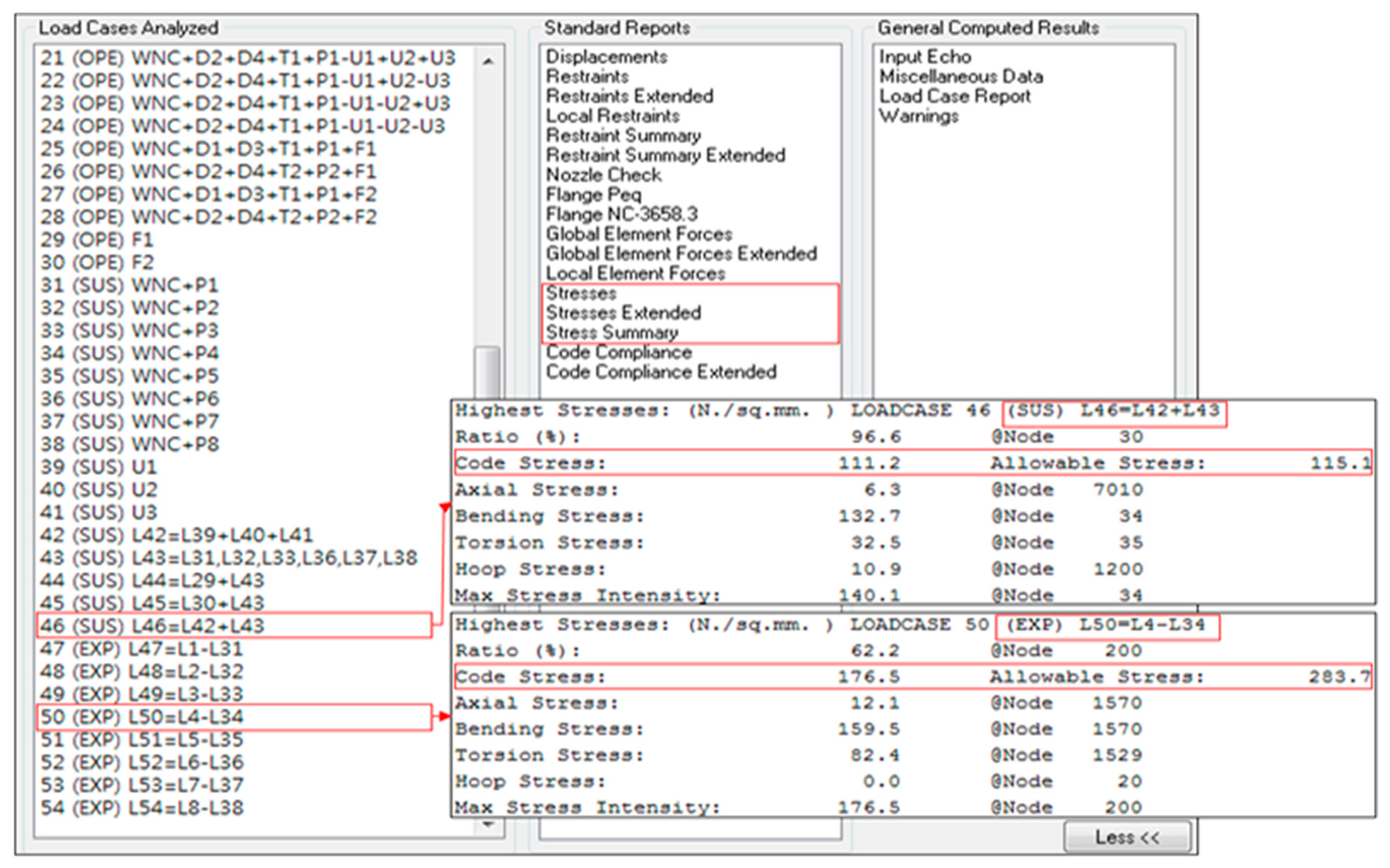
The piping stress analysis was performed on the trunk deck of the LNG carrier, the piping around the liquid dome, and the main gas tank area. The piping system components were extracted from the diagram shown in Figure 4 and modeled using CAESAR-II. Figure 5 shows the results of geometric modeling and finite element modeling. Figure 6 describes the schematic procedure of the component modeling. The piping modeling procedure consists of four steps: (1) define the component of piping system; (2) define the node coordinates; (3) assign piping configuration attributes (information such as length, diameter and thickness); (4) assign the pressure and the thickness and density of the insulation layer [19]. The type of valve, the connection and pressure class of the valve, and the length and weight of the valve were defined. In the expansion joint, the type of pressure and load type are first modeled. Next, the length and axial stiffness of the expansion joint are defined.

4.2. Load Cases

As mentioned in the previous sections, hull displacements due to longitudinal bending deformation and radiant thermal deformation are represented as boundary conditions at supporting points. Forced displacement due to the thermal deformation from the hull deck and forced displacement by hogging/sagging were applied to the support. Hull motion acceleration was applied to the entire piping system using Equations (16)–(20) to reflect the inertia force. The load condition was defined as 54 cases by combining operating conditions, sustained load conditions, and expansion load conditions as shown in Figure 7. The combination of the loads is based on the ASME B31.3, Process Piping specification [3].

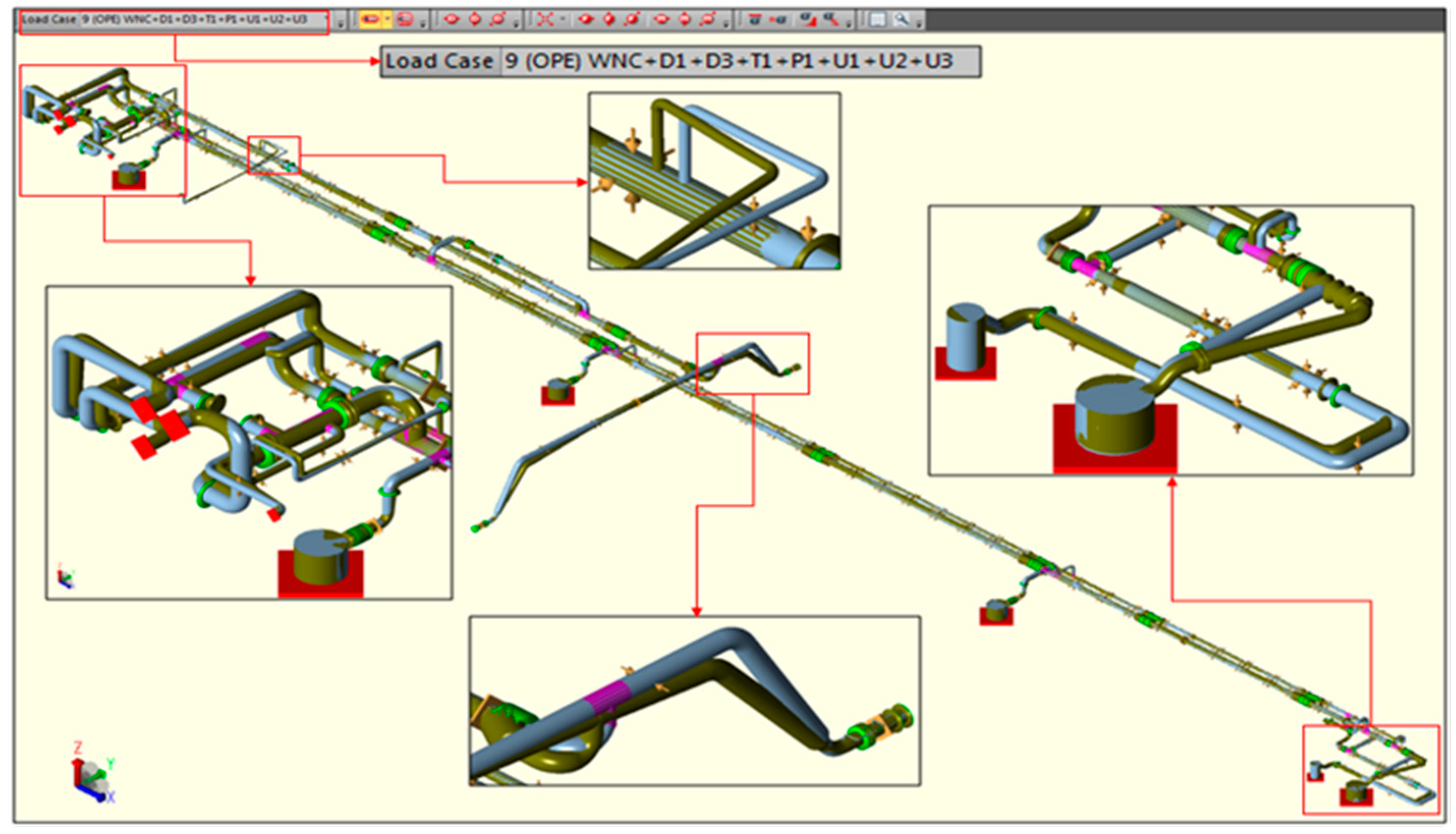
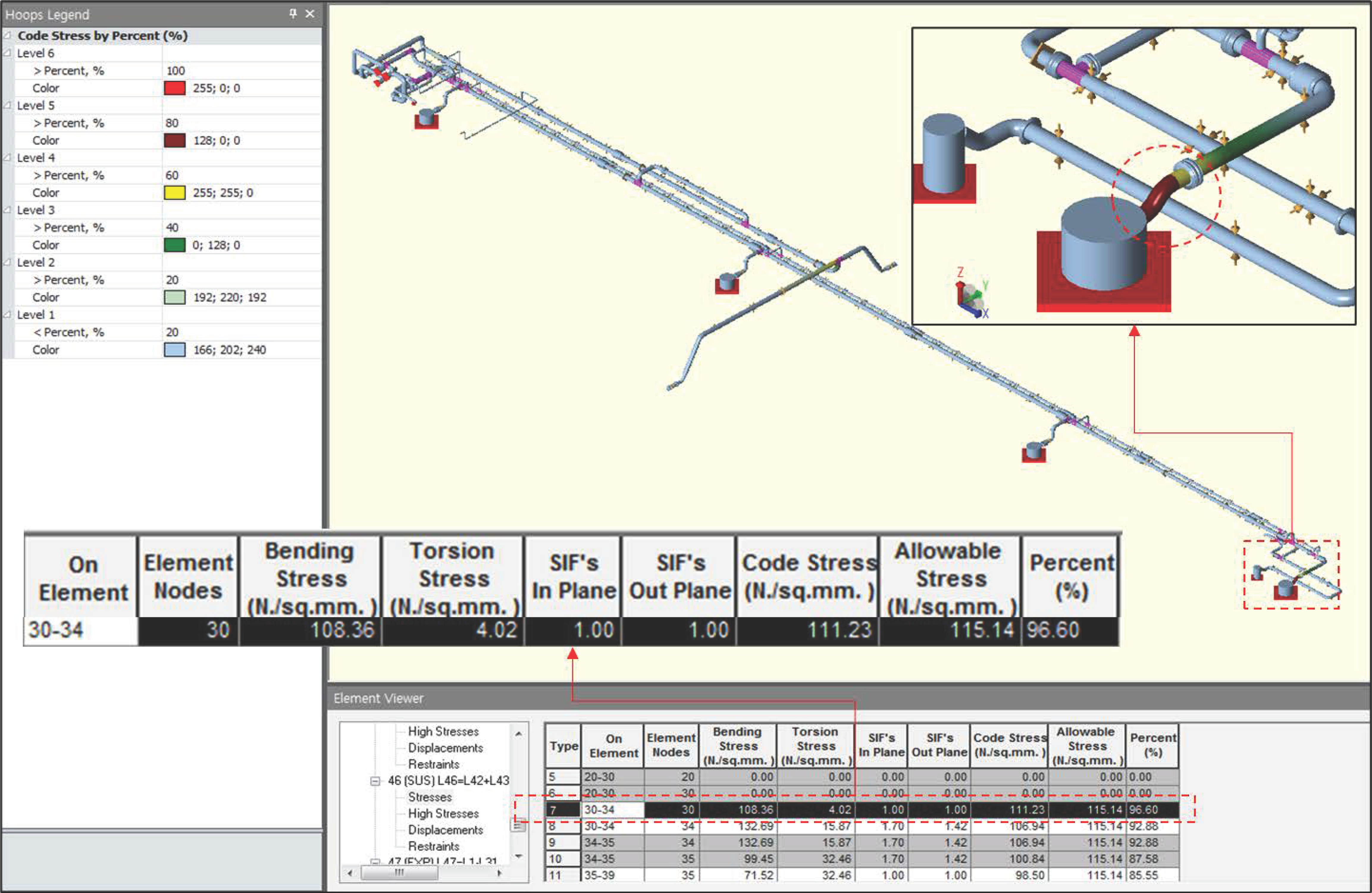
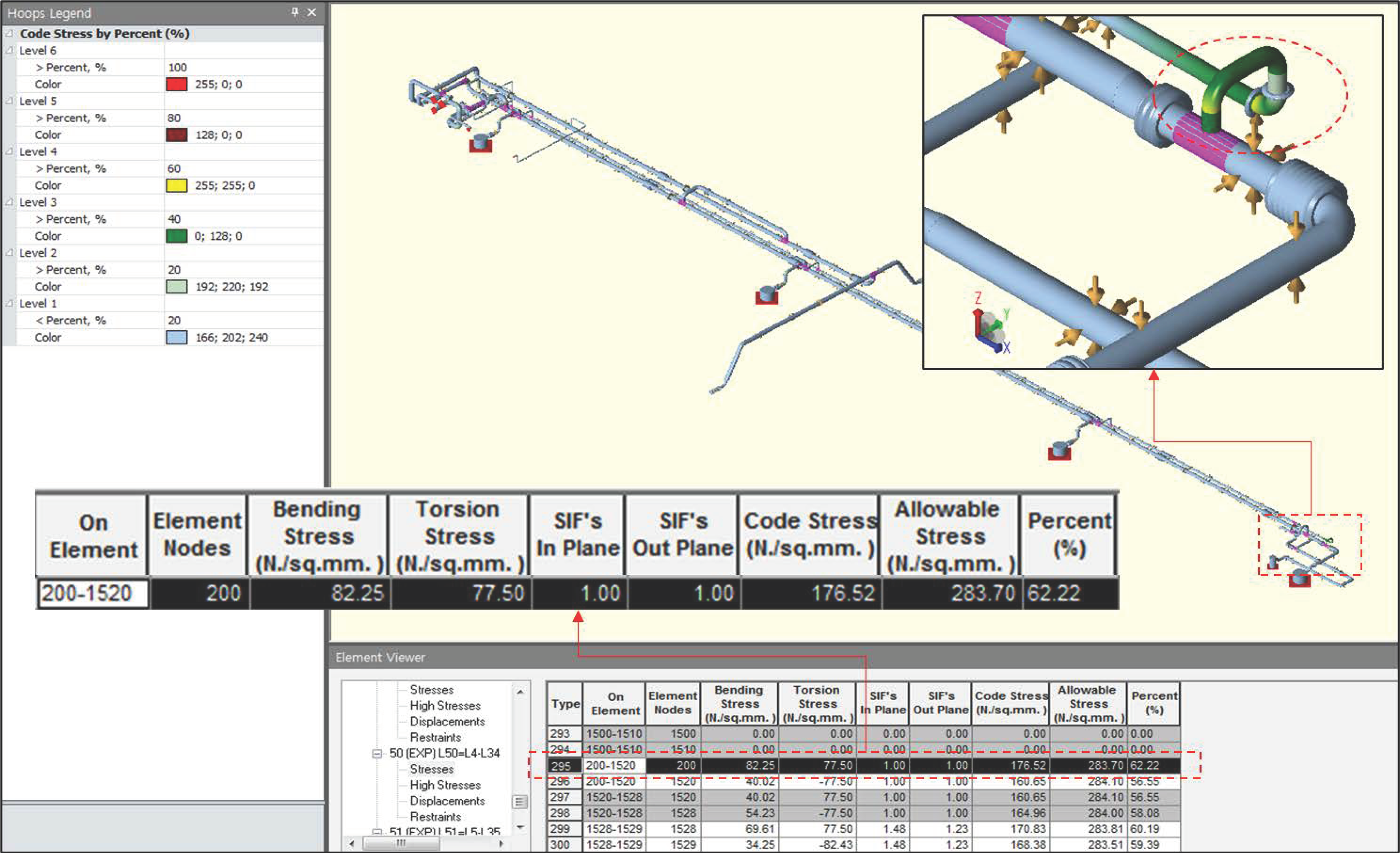
4.3. Deformation and Stresses

Stress, reaction force, moment, and deformation were obtained at the support and anchor from the load combination of the operating conditions [24]. Figure 8 shows the deformed shape of the pipes, the deformation of the expansion joint and the curved pipes.
Table 8 summarizes the calculated stresses and allowable stresses for each combination of loads. Code stress means the maximum stress calculated for each load case. The combination of sustained loads means that the self-weight and pressure of the piping is combined according to the operating temperature. Figure 9 shows the maximum stress and its location for the load cases of L46 and L50. L46 code stress is 111.2 MPa, which is smaller than the allowable stress (115.1 MPa). The allowable stress of L50 was 283.7 MPa, while the code stress (maximum stress) was calculated to be 176.5 MPa. Figure 10 shows the details of the bending stress, torsional stress, and stress intensity factor of L46. Figure 11 shows detailed results for L50 where the maximum stress occurred in all load cases. The stressed part of each load case was observed in the pressure vessel, the connecting part, and the curved pipes.

5. Conclusions

A structural safety analysis of the piping system on LNG carriers was performed using the pipe elements provided by CAESAR-II software. An evaluation of the analytical results was conducted in accordance with ASME B31.3 [3] (the standard code for process piping) and DNV GL rules [18]. The proposed method provides a systematic procedure that can be applied to the piping arrangement of LNG carriers. A stress analysis procedure of the LNG ship using CAESAR-II software was proposed, which can simultaneously consider beam element behavior and ASME design code. The difference in piping system stress analysis procedures between onshore plant and offshore structures such as LNG carriers was determined. The outcomes of this study can be summarized as follows:
  • The structural safety of the piping system installed on the LNG carriers was evaluated by reflecting the thermal deformation of the hull and inertial effects caused by hull motion.
  • Pipe stresses were analyzed to reflect the attributes of valves, expansion joints and flanges in the piping system of the LNG carrier.
  • Sustained, occasional, and secondary load conditions were defined as a combination of load boundary conditions.
  • The stresses were analyzed for each load condition and load combination and the stresses were evaluated in accordance with the criteria of the ASME code.

Author Contributions

J.-H.L. suggested the concept of thermal stress analysis of processing piping system; S.-Y.H. analyzed the data and suggested an analysis procedure; M.-S.K. and S.-Y.H. performed case study based on finite element analysis; S.-Y.H. and J.-H.L. wrote the paper. All authors have read and agreed to the published version of the manuscript.

Funding

This research was funded by an INHA University research grant.

Acknowledgments

This research was supported by an INHA University research grant.

Conflicts of Interest

The authors declare no conflict of interest.

References

  1. Lu, H.; Ma, G.; Li, X.; Wu, S. Stress Analysis of LNG Storage Tank Outlet Pipes and Flanges. Energies 2018, 11, 877. [Google Scholar] [CrossRef] [Green Version]
  2. Yu, G.P.; Zhao, G.M.; Zhang, Y.X. Stress analysis of cryogenic LNG pipeline. Petrochemistry 2015, 32, 22–25. [Google Scholar]
  3. American Society of Mechanical Engineers. ASME, B31.3—Process Piping—ASME Code for Pressure Piping; American Society of Mechanical Engineers: New York, NY, USA, 2014. [Google Scholar]
  4. American Society of Mechanical Engineers. ASME. B31.1. in Power Piping—ASME Code for Pressure Piping; American Society of Mechanical Engineers: New York, NY, USA, 2012. [Google Scholar]
  5. Wang, C.Z. Analysis for Cargo Handling Pipeline of LNG Carrier. Master’s Thesis, Shanghai Jiao Tong University, Shanghai, China, 2011. [Google Scholar]
  6. Wang, W.; Peng, Y.; Zhou, Y.; Zhang, Q. Liquid sloshing in partly-filled laterally-excited cylindrical tanks equipped with multi baffles. Appl. Ocean. Res. 2016, 59, 543–563. [Google Scholar] [CrossRef]
  7. Ito, H.; Suh, Y.S.; Chun, S.E.; Satish Kumar, Y.V.; Ha, M.K.; Park, J.J.; Yu, H.C.; Wang, B. A direct assessment approach for structural strength evaluation of cargo containment system under sloshing enside LNGC tanks based on fluid structure interaction. In Proceedings of the ASME 2008 27th International Conference on Offshore Mechanics and Arctic Engineering, Estoril, Portugal, 15–20 June 2008; Volume 5, pp. 835–845. [Google Scholar]
  8. Jeong, S.Y.; Yoon, K.B.; Dytet, P.V.; Yu, J.M.; Kim, J.Y. Structural integrity evaluation by system stress analysis for fuel piping in a process plant. KOSOS 2013, 28, 44–50. [Google Scholar]
  9. Sharma, P.; Tiwari, M.; Sharma, K. Design and analysis of a process plant piping system. IJCET 2014, 3, 31–39. [Google Scholar]
  10. Lu, H.; Huang, K.; Wu, S. Vibration and stress analyses of positive displacement pump pipeline systems in oil transportation stations. JPSEM 2015, 7, 501–502. [Google Scholar] [CrossRef]
  11. Miranda, J.L.H.; López, L.A.A. Piping Design: The Fundamentals. In Proceedings of the Short Course on Geothermal Drilling, Resource Development and Power Plant, Santa Tecla, El Salvador, 16–22 January 2011. [Google Scholar]
  12. Shang, B.; Li, C.; Lu, H. Stress analysis of suspended gas pipeline segment. JPSEM 2017, 8. [Google Scholar] [CrossRef]
  13. Sohail, M.; Venukumar, S.; Reddy, M.V. An outline of piping design using CAESER II-Case Study. MTP 2017, 4, 8269–8278. [Google Scholar] [CrossRef]
  14. Intergraph CAS Inc. CAESAR II (Version 8); Intergraph CAS Inc.: Madison, AL, USA, 2016. [Google Scholar]
  15. Wu, X.; Lu, H.; Wu, S. Stress analysis of parallel oil and gas steel pipelines in inclined tunnels. SpringerPlus 2015, 4, 659. [Google Scholar] [CrossRef] [PubMed] [Green Version]
  16. Brown, T.S.; Jukes, P.; Sun, J. SS: Cryogenic Pipeline-Mechanical Design of Subsea and Buried LNG Pipelines; Offshore Technology Conference: Houston, TX, USA, 2009. [Google Scholar]
  17. Ju, X.; Fang, W.; Yin, H.; Jiang, Y. Stress analysis of the subsea dynamic riser base process piping. JMSA 2014, 13, 327–332. [Google Scholar] [CrossRef]
  18. DNV GL. DNVGL-RP-D101 Structural Analysis of Piping Systems; DNV GL: Oslo, Norway, 2017. [Google Scholar]
  19. Rani, M.J.; Ramanathan, K. Design and analysis of piping system with supports using Caesar-II. World Acad. Sci. Int. J. Mech. Aerosp. Ind. Mechatron. Manuf. Eng. 2016, 10, 919–923. [Google Scholar]
  20. Tambe, P.N.; Dhande, K.K.; Jamadar, N.I. Flexibility and stress analysis of piping system using Caesar-II-case study. IJERT 2014, 3, 370–374. [Google Scholar]
  21. American Society of Mechanical Engineers. ASME. B16.5—Pipe Flanges and Flanged Fittings: NPS 1/2 through NPS 24 Metric/Inch Standard; American Society of Mechanical Engineers: New York, NY, USA, 2013. [Google Scholar]
  22. International Maritime Organization. IGC Code 2016 Amendments. In Code for the Construction and Equipment of Ships Carrying Liquefied Gases in Bulk; International Maritime Organization: London, UK, 2016. [Google Scholar]
  23. Bhave, S.U. Calculation methodologies for the design of piping systems. IJERGS 2014, 2, 596–603. [Google Scholar]
  24. Xu, Z.Y.; Hui, H. Finite element analysis of top inlet pipe for LNG storage tanks. JCIEC 2015, 66, 354–359. [Google Scholar]
Figure 1. Bending moments in pipes (American Society of Mechanical Engineers (ASME), 2014) [3].
Jmse 08 00926 g001
Figure 2. Flexibility factor and stress intensification factor (ASME, 2014) [3].
Jmse 08 00926 g002
Figure 3. International Organization for Standardization (ISO) drawing of main liquid pipeline.
Jmse 08 00926 g003
Figure 4. ISO drawing of liquid main of liquefied natural gas (LNG) piping system used for case study.
Jmse 08 00926 g004
Figure 5. Geometry and finite element model of piping system.
Jmse 08 00926 g005
Figure 6. Schematic procedures for modeling pipes.
Jmse 08 00926 g006
Figure 7. Combined load cases for stress analysis.
Jmse 08 00926 g007
Figure 8. Maximum stress of pipeline.
Jmse 08 00926 g008
Figure 9. Maximum stress of LNG pipeline of L46 and L50.
Jmse 08 00926 g009
Figure 10. Maximum stress of LNG pipeline of L46.
Jmse 08 00926 g010
Figure 11. Maximum stress of LNG pipeline of L50.
Jmse 08 00926 g011
Table 1. Material property of stainless-steel pipe.
Temperature (°C)Elastic Modulus
E ( N / m m 2 )
Thermal Expansion α (mm/mm/°C)Allowable Stress ( S c ) , ( S h ) (MPa)
80191,11816.73 × 10 6 115.14
40193,60016.50 × 10 6 115.14
21195,12216.40 × 10 6 115.14
−140205,43015.15 × 10 6 115.14
−160206,62214.99 × 10 6 115.14
−163206,80114.96 × 10 6 115.14
−196208,76614.69 × 10 6 115.14
Table 2. Material property and thickness of pipe insulation.
Nominal Diameter of PipeInsulation Thickness (mm)Insulation Density (Kg/ m 3 )
Liquid Line Gaseous Line Fuel Gas
DN 25 and below30303040
DN 32 to DN 10050403040
DN 125 and above80603040
Table 3. Fluid characteristics of pipe.
Material Density (Kg/ m 3 ) CAESAR-II Input (kg/ dm 3 )
Vapor natural gasInsignificant0.00
Liquid natural gas4700.47
Return components4700.47
Table 4. Acceleration of ship motion.
DirectionLongitudinal Direction ( a x )Transverse Direction ( a y )Vertical Direction ( a z )
Area
Deck0.19 g0.72 g0.55 g
Table 5. Forced displacement acting on the deck.
DeformationLoadingDeformation Ratio (mm/m)
Deck expansionHogging deformation0.81 on longitudinal direction
Solar radiation heating0.29 on transverse and longitudinal direction
Deck ShrinkageSagging deformation0.70 on longitudinal direction
Solar radiation heating0.47 on transverse and longitudinal direction
Table 6. Load conditions for stress assessment.
Load CaseLoads
Sustained caseAcceleration (U), weight (WNC), pipe pressure (P)
Expansion caseThermal deformation
Forced displacement by hull bending and thermal deformation
Table 7. Load condition for reaction force and displacement of pipe in support.
Load CaseLoads
Operation caseLinear superposition of sustained cases and expansion cases
Operation temperature (T1), max/min temperature cases (T2)
Table 8. Maximum stresses of load cases.
Load CaseCombined LoadsStress TypeCode Stress (MPa)Allowable Stress (MPa)Ratio (%)Node
L31WNC+P1SUS109.3115.194.930
L32WNC+P2SUS109.3115.194.930
L33WNC+P3SUS109.3115.194.930
L34WNC+P4SUS109.3115.194.930
L35WNC+P5SUS109.3115.194.930
L36WNC+P6SUS76.9115.166.85760
L37WNC+P7SUS76.9115.166.85760
L38WNC+P8SUS109.3115.194.930
L42L39+L40+L41SUS16.7115.114.56330
L43L31~33, L36~38SUS109.3115.194.930
L44L29+L43SUS109.3115.194.930
L45L30+L43SUS109.3115.194.930
L46L42+L43SUS111.2115.196.630
L47L1-L31EXP164.6270.360.95259
L48L2-L32EXP79.628527.97869
L49L3-L33EXP149.3283.752.6200
L50L4-L34EXP176.5283.762.2200
L51L5-L35EXP86.2280.130.87259
L52L6-L36EXP0.2281.20.16580
L53L7-L37EXP104.5283.736.8200
L54L8-L38EXP164.6270.360.95259
Publisher’s Note: MDPI stays neutral with regard to jurisdictional claims in published maps and institutional affiliations.

