1. Introduction
A rapid integration of some European and Asian countries into the system of international transport corridors has required formation of combined transport systems [
1,
2,
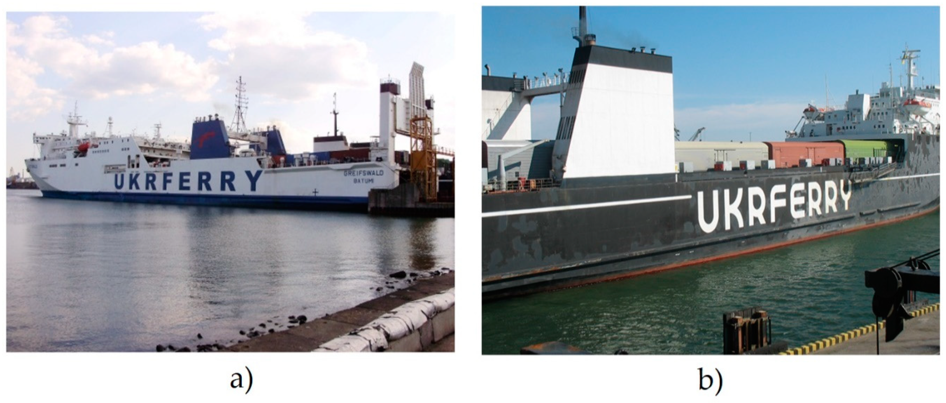
3], one of the most promising of which is the rail/ferry transportation. A special characteristic of such transportation is possibility to transport rail vehicles by special transport means—train ferries (
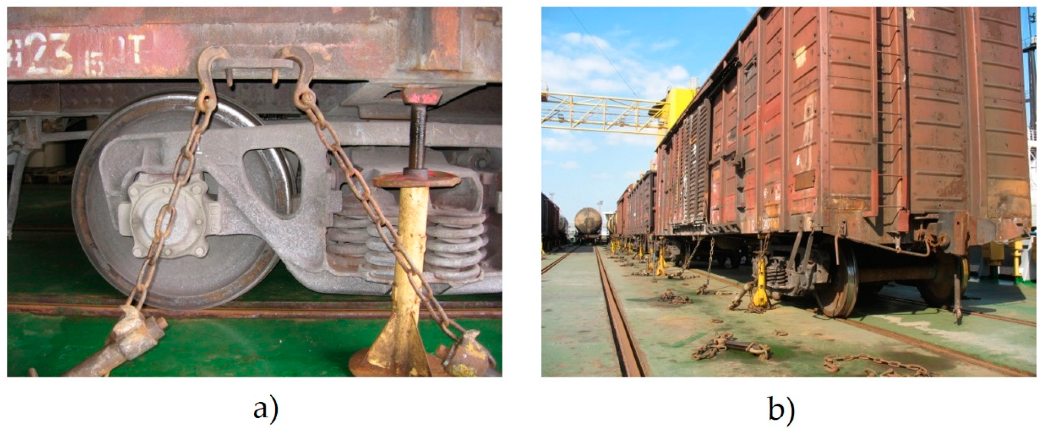
Figure 1). The rail vehicles transported are located on the deck tracks. The wagons are secured on the deck with typical multiple-use lashing devices. Among them are chain binders (eight units per wagon), mechanical support jacks (four units per wagon), brake shoes installed under the end wagon wheels in the bathes, and buffer stops (
Figure 2).
The chain binders are rigidly fastened on the deck. The initial preload of a chain binder is 5–6 tons. The binder must retain a load of 20 tons.
At sea transportation various forces can emerge and impact the carrying structure of a rail vehicle. The most significant type among them is a dynamic load. Therefore, in order to ensure safe transportation of rail vehicles by train ferries, there is a need to research into dynamic forces on the carrying structure of a rail vehicle and establish some recommendations aimed at provision of safe transportation.
The study of statistical data on damage to the load-bearing structures of wagons when traveling by sea, carried out by the authors of the article, showed that annually about 10% of wagons from the total wagon turnover in international rail–ferry traffic between Ukraine and Bulgaria need to be repaired. The largest percentage of damage to wagons is in open wagons and covered wagons. At the same time, the existing regulatory documents do not fully sanctify the peculiarities of loading wagons during transportation on rail ferries. This makes it necessary to study the dynamic load and strength of wagons by means of mathematical and computer modelling in order to ensure the safety of transportation by sea.
The issues of studying the dynamic load and strength of the load-bearing structures of cars during transportation on rail ferries were considered in the previous works of the authors of the article. However, they were aimed at improving the very design of the wagon in order to adapt it to secure anchorage on the deck of a railway ferry. At the same time, no attention was paid to improving the scheme of securing the supporting structure on the deck with the possibility of reducing the dynamic load on it.
Some peculiarities of strength calculation for the carrying structure of a rail vehicle are considered in [
4,
5]. The calculation was made by the finite element method (FEM). The results of the calculation were proved by experimental research.
The computer modelling of strength for the carrying structure of a wagon is given in study [
6]. The current work determined dislocation fields of the maximum equivalent stresses and displacements for the carrying structure of a wagon. However, in their calculation of the carrying structure strength of a wagon the current work neglected the forces emerging under ferry transportation, in spite of the fact that these forces considerably exceed ones imposing on the wagon in operation on the railway tracks.
The research into dynamic loading on a C70 wagon under operation loading modes is presented in [
7]. The study considers the normative values of operation loads.
The basic dynamic indices of wagons are defined in [
8]. It considers transverse travels of bogies on the track. The current work estimated an effect of transverse travels upon the traffic safety indicators. However, in their publications the authors do not focus on an issue of dynamic load on the rail vehicles under train ferry transportation.
The dynamic load on rail vehicles transported by ferries is explored in studies [
9,
10]. The current work present mathematical and computer models for determination of dynamic load and strength of rail vehicles. However, the studies do not provide peculiarities of verification for these models, and authors do not suggest any measures aimed at a decrease of dynamic load on the rail vehicles.
The objective of the article is determination of dynamic forces on and strength of wagons under train ferry transportation. The following tasks were set to achieve the objective:
mathematical modelling of dynamic forces on the carrying structure of wagons transported by train ferries;
computer modelling of dynamic forces on the carrying structure of wagons transported by train ferries;
adequacy check for the models of dynamic forces on the carrying structure of wagons under train ferry transportation;
strength calculation for the carrying structure of wagons under train ferry transportation;
suggestions concerning an improved fixation diagram for the wagons on the train ferry, which decreases dynamic forces on the wagon, mathematical modelling, calculation of strength and stability of the carrying structure of a wagon under train ferry transportation.
2. Mathematical Modelling of Dynamic Forces on the Carrying Structure of a Wagon under Train Ferry Transportation
The dynamic load on a wagon transported by train ferry was studied at a mathematic model considering the forces on the wagon body at ferry roll [
11]
where
D—weight water displacement of a ferry,
zg—coordinate of the ship’s centre of gravity,
B—ferry breadth,
h—moulded depth,
Λθ—roll damping coefficient,
p′—wind force on the above-water body, and
Z(
t)—law of force action disturbing motion of the ferry loaded with wagons on the deck.
This oscillation type was taken as basic because it greatly impacts stability of a wagon on the deck. The model does not consider an impact effect from waves on the train ferry body. The trochoidal motion of a sea wave and the wind loading on the above-water projection were taken as disturbing actions [
12]. The current work studied the case when the wagon was rigidly fixed on the deck; thus, the wagon was considered as an attached mass, which completely repeated a trajectory of the train ferry under oscillations.
Equation (1) can be written as follows
Let us solve non-homogeneous Equation (2) with the method of variation of constants according to which the solution to Equation (2) must be searched as [
13]
where
—functions to be defined,
—solutions to the homogeneous equation.
The general solution to the differential motion equation for the wagon has the following form
where
a and
b—horizontal and vertical coordinates of the centre of trajectory along which the ferry travels,
X and
Z are coordinates of the ferry,
R—radius of the trajectory along which the ferry travels,
k—frequency of the trajectory of disturbing action,
ω—forced vibration frequency, and
ν—frequency of free oscillations of the ferry.
The total value of acceleration on the wagon body was defined as a sum of accelerations to the place of a wagon on the deck and the acceleration conditioned by the horizontal component of the gravitational acceleration
where
g—gravitational acceleration,
θ—roll angle.
The current work calculated the numerical value of acceleration on the wagon under ferry transportation. It was considered that the ferry operates in the Black Sea. The calculation was based on the parameters of the Heroi Shipki train ferry fully loaded with 108 rail vehicles.
The calculation conducted made it possible to conclude that the acceleration on the carrying structure of a wagon transported by sea was 0.25 g.
3. Computer Modelling of Dynamic Forces on the Carrying Structure of a Wagon during Train Ferry Transportation
To check the dynamic loads obtained using mathematical modelling, computer modelling was carried out. The current work built a spatial model of a fragment of the train ferry Heroi Shipki in SolidWorks software for computer modelling of dynamic forces on the wagon body located on the train ferry under sea disturbance [
14,
15,
16,
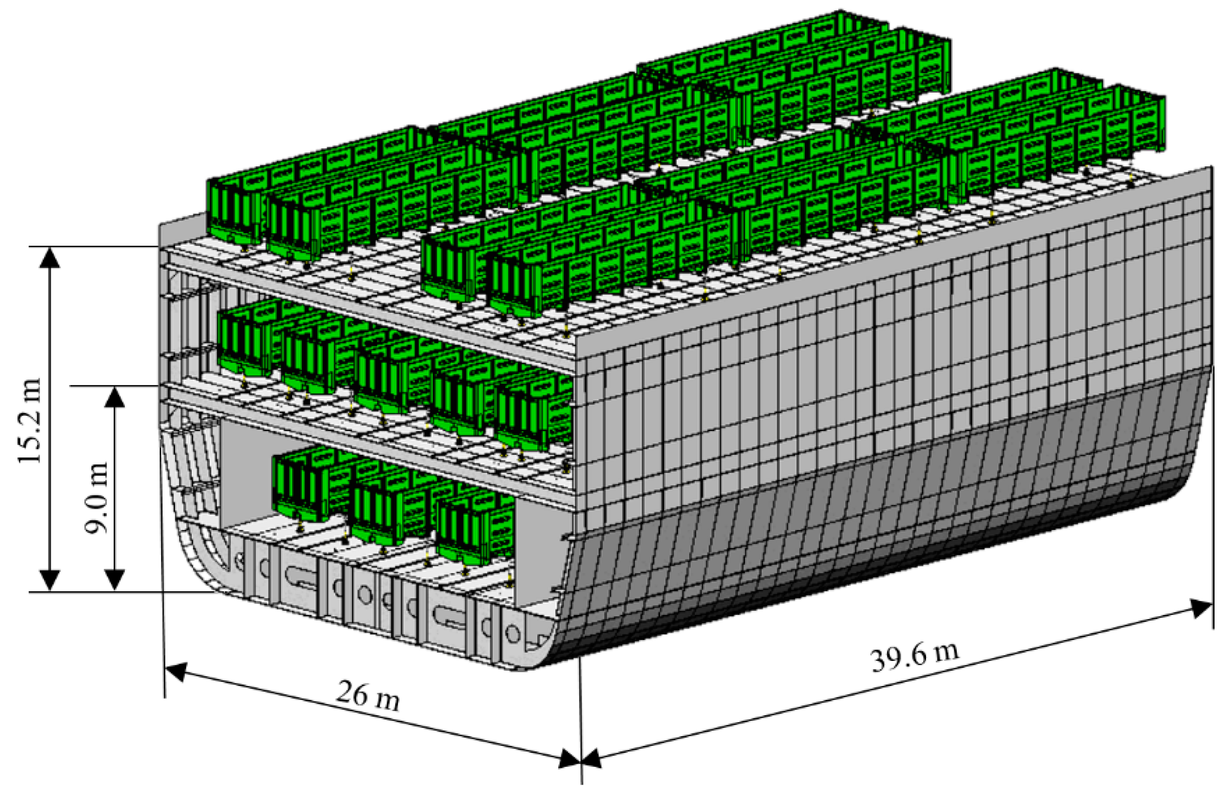
17]. The model considered the basic structural elements of the ferry body. The length of the model was 39.6 m and the breadth 26 m. In this case, drawings of a railway ferry were used. When creating the model, the main structural elements of the railway ferry were taken into account: side sheathing, keel belt, floor, keel, bottom stringer, frame, side stringer, knit, beams, deck flooring, longitudinal hatch coaming, transverse hatch coaming, shirstrek, bilge sheathing sheet, and railway rails. A 12-757 open wagon manufactured at the Kryukovsky Railway Car Building Works was chosen for the research. The spatial model of the fragment of the train ferry loaded with open wagons on the deck is given in
Figure 3.
Based on the spatial model, a computational model was built to determine the acceleration of wagons located on the train ferry. The calculation was made with the FEM in CosmosWorks software. A working scheme of the solution was used in the work. Isoparametric tetrahedrons were used for creating a finite element model. In this case, nonlinear finite elements were used. The optimal dimensions of its mesh were defined by the graphic analytical method [
18,
19,
20,
21]. The method is based on graphical (geometric) presentation of feasible solutions and objective function of the problem [
22,
23,
24]. The essence of the method for solving this problem is to plot the dependence of the maximum equivalent stresses on the number of finite elements. When this dependence begins to be described by a horizontal line, this is the optimum in the number of finite elements. The number of nodes in the mesh was 149,223 and the number of elements 500,354. The maximum size of an element was 1000 mm and the minimum 200 mm. The minimum number of elements in a circle was 15, the size gain ratio of elements in a mesh was 1.8. The maximum size ratio was 9.5 ∙ 10
5, the percent of elements with a size ratio less than three was 6.96 and more than ten was 81.5.
The model considered the following forces on the train ferry: vertical static
Pvst, conditioned by gross weight of ferry; wind force
Pw; hydrostatic force
Ph on the underbody of the ferry; buoyancy force
Pb; forces on the ferry deck through the rail cars both vertical
Pbv and horizontal
Phv; and also forces on the deck through the multiple-use lashing devices, i.e., chain binders
Pcb and mechanical support jacks
Pj (
Figure 4).
Due to the fact that a fragment of a railway ferry was taken into account in the calculations, in order to take into account its folded part in the corresponding sections, efforts were applied (vertical, longitudinal, and transverse), the numerical values of which were determined by the method of sections.
When determining the loads acting on the deck by means of wagons placed on it, the 12.2° roll angle of the railway ferry was considered. In this case, the horizontal load from the flanges of the wheels on the rails is applied from their inner side. It includes the gravitational acceleration component and the wind load. When determining the wind load acting on the surface projection of a railway ferry with wagons located on the upper deck, a wind pressure of 1.47 kPa was considered.
To simulate the forces acting on the deck through the chain ties, pads whose configuration was identical to the geometry of the eye-to-deck area were used (
Figure 5).
Due to the spatial placement of the chain ties, the forces acting on the deck through them were decomposed into components, taking into account the angles of the ties in space (
Figure 6). In the bearing zones of the mechanical stop-jacks, pads were also installed on the deck, the geometry of which repeats the geometry of the support part of the stop-jack.
As a material for the model of a railway ferry, steel grade D was used, for which the value of the ultimate strength σB = 440–590 MPa and yield strength σT = 315 MPa was used, for the supporting structure of the car, steel 09G2S was used with the value σB = 490 MPa and σT = 345 MPa.
On the basis of the calculation conducted it was established that the maximum accelerations exerted the wagons located on the end tracks from the bulwarks and accounted for about 0.3 m/s
2 (
Figure 7). The total acceleration value with consideration of the horizontal component of the gravitational acceleration was 2.38 m/s
2 (0.24 g).
4. Adequacy Check for Dynamic Force Models of the Carrying Structure of Rail Vehicles under Train Ferry Transportation
The models were checked for adequacy with an F-test [
25,
26,
27] This criterion was chosen as the determining one because it is one of the most used in technical calculations.
where
Sad2—dispersion of adequacy,
Ssq2—error mean square. The dispersion of adequacy was found by the formula
where
yip—calculated value of the parameter obtained by modelling,
fi—number of degrees of freedom.
where
N—number of tests in the planning matrix,
q—number of coefficients of equation. The error mean square was defined by the formula
where
Si2—dispersion in each line under parallel experiments.
Let us consider that the model under consideration is a linear model, i.e., it is a one-factor model, and it characterizes changes in accelerations of wagon bodies according to the roll angle of a train ferry. The results of modelling are given in
Table 1.
On the basis of the calculation it was obtained that the error mean square was Sy2 = 1.73, and the dispersion of adequacy Sad2 = 1.8. It was established that the actual value of an F-test was Fp = 1.04, which was less than the tabular value of the criterion Ft = 3.29. Therefore, the hypothesis of adequacy of the model developed was not rejected.
5. Strength Calculation for the Carrying Structure of Rail Vehicles under Train Ferry Transportation
The strength of an open wagon body in interaction with multiple-use lashing devices under sea transportation was studied with a spatial model built in SolidWorks software.
The model considered the elements rigidly linked to each other (by welding or pivoting). As far as the hatch covers were not rigidly connected with the body frame, but through joint coupling, and acted as the elements transferring forces to the rigidly connected frame elements, they were neglected in the model.
The design model did not consider the longitudinal forces on the open wagon body through an automatic coupler, as they were limited by the buffer stop, mounted at the batch ends, and by the brake shoes. The open wagon body was fixed with additional simulated connections in the zones where the body rested on the base plates of bogies, the sliders, and the support jacks.
The calculation was made by the FEM in CosmosWorks software [
28,
29]. The design diagram of an open wagon body (
Figure 8) considered the following forces: vertical static
Pvst, force from the bulk freight
Pp, wind force
Pw, and forces on the wagon body through the chain binders
Pch.
Due to the spatial location of the chain binder, the force transferred to the carrying structure of an open wagon body through it, was decomposed.
The finite element model consisted of isoparametric tetrahedrons, the optimal number of which was determined by the graphic analytical method. The number of elements in a mesh was 494,440, and the nodes—160,329. Black coal was chosen as bulk freight being one of the most common type of freight transported in open wagons by sea. The force from the bulk freight to the walls of an open wagon body was determined by the method based on the principle of Coulomb’s law used in calculation of support walls with B.V. Sinelnikov’s adjustment [
30]. In addition, the calculation took into account the acceleration value on the wagon body.
Then, the force from the bulk freight was defined by the formula,
where
γ′—volume weight of freight,
h′—wagon body height,
ρ′—angle of internal friction,
α′—tilt angle of car, and
—additional force conditioned by dynamic component on bulk freight under ferry oscillations.
On the basis of the calculation it was established that the maximum pressure from the bulk freight to the side wall of an open wagon body was about 15 kPa. The results of the calculation are given in
Figure 9.
The results of the calculation demonstrated that the maximum equivalent stresses were 443.2 MPa. The stress value obtained exceeded the admissible value [
31,
32,
33]. The yield stress of the material
σT = 345 MPa was considered as permissible stresses.
Therefore, considering a typical fixation diagram for an open wagon on the deck, the maximum equivalent stresses in the body elements exceeded the admissible values. It can cause damage in the fixation elements, their breaking-off, and, as well, a stability loss of an open wagon on the deck.
6. An Improved Fixation Diagram of Lower Dynamic Loading on Rail Cars Transported by Train Ferries
The current work suggests application of viscous connection between body and deck, which can decrease the dynamic loading on the wagon under train ferry transportation. It can be achieved with an application of the chain binder presented in
Figure 10.
The special feature of the binder is that under angular displacements of a wagon the piston moves relative to the case by viscous resistant forces, which decreases forces to the wagon body. The binder begins to function at the load force over 5 tons.
The current work conducted mathematical modelling to substantiate the application of viscous connection for the wagons. The mathematic model is presented below [
34]
where
q1,
q2—generalized coordinates corresponding to angular displacement along the longitudinal axle of a train ferry and a wagon body, respectively;
Ik—inertia moment of a wagon body relative to the longitudinal axle;
β—viscous resistance coefficient;
B—body width;
pk—wind force on the sidewall of a wagon;
hk—height of the sidewall of a car; and
Fβ—moment of forces between the wagon body and the deck. The results of calculating the strength of the open wagon supporting structure, taking into account the fastening with viscous ties on the deck of the railway ferry, are shown in
Figure 11.
Stability of the carrying structure was also calculated. The design diagram is given in
Figure 12.
The stability of the wagon carrying structure on the deck should meet the following condition
where
Mst—stability moment value,
Mcap—capsizing moment value.
where
Mbr—gross mass of the carrying structure of a wagon,
Pbr—gross weight of the carrying structure of a wagon,
nc—number of chain binders on one side of a wagon used for fixation of the body. The calculation was conducted for the deadweight tonnage and demonstrated that the viscous binder can improve stability of the wagon on the deck by 10% in comparison with that for a standard binder.
7. Discussion of Research Findings
The current work researched the dynamic load and the strength of carrying structures of rail vehicles in terms of safe transportation by train ferries. The study is based on mathematical modelling of dynamic forces on the carrying structure of a rail vehicle. It was established that the maximum value of acceleration on the carrying structure of a wagon was 0.25 g. In addition, the current work conducted the computer modelling of dynamic forces on the carrying structure of a wagon, checked the adequacy of the findings obtained, and defined stability values for the carrying structure of a wagon under transportation by train ferry. It was established that the maximum equivalent stresses did not exceed the admissible values.
The current work proposed application of the viscous binder for fixation of wagons on the deck to ensure safe transportation of rail vehicles by train ferries. The results of mathematical modelling made it possible to conclude that the dynamic forces decreased by 30% in comparison with that at a typical binder. The results of the calculation for strength and stability also proved an efficiency of the solution suggested.
The research limitation was neglect of own oscillations of the wagon located on the ferry. The current work will study it in its further research.
The research conducted can contribute to safe transportation of rail cars by sea, development of recommendations and norms for design and calculation of carrying structures of rail cars, and improved efficiency of combined transportation.
8. Conclusions
The current work conducted the mathematical modelling of dynamic forces on the carrying structure of a wagon under train ferry transportation. It was made for the rolling motion and considered the rigid fixation of rail vehicles on the deck. The results of modelling demonstrated that the maximum acceleration on the wagon was about 0.25 g.
The current work conducted the computer modelling of dynamic forces on the carrying structure of a wagon under train ferry transportation. The calculation was made using the FEM in CosmosWorks software with determination of the dislocation fields and the values of maximum acceleration on the carrying structure of a wagon. The total value of acceleration was 0.24 g.
The models of dynamic forces on the carrying structure of rail vehicles under train ferry transportation were checked for adequacy with an F-test. It was established that the hypothesis on adequacy was not rejected.
The strength calculation of the carrying structure of a wagon under train ferry transportation was also conducted and the maximum equivalent stresses in the carrying structure of a wagon were defined. It was established that the stresses were concentrated in the zones of fixation on the deck. The maximum equivalent stresses were 443.2 MPa, which exceed the admissible values.
The current work suggested an improved diagram for fixation of rail vehicles on the train ferry to provide lower dynamic forces on a wagon with application of the viscous binder. They conducted the mathematical modelling, strength, and stability calculation for the carrying structure of a wagon under train ferry transportation. It was established that with the viscous binder between the wagon body and the deck it was possible to decrease the acceleration value on the carrying structure of the body by 30%.
The research presents strength calculation for the carrying structure of a wagon. The calculation demonstrated that the maximum equivalent stresses in the carrying structure of a wagon were about 280 MPa, which meant that strength of the carrying structure of a wagon was provided.
The research also deals with stability of the carrying structure of a wagon on the deck. It was established that the viscous binder can improve the stability of a wagon body located on the deck by 10% in comparison with that for a typical binder.
The research conducted can contribute to safe transportation of rail vehicles by sea and higher efficiency of combined transportation.


