Article

Application of Shielding Coils in Underwater Wireless Power Transfer Systems

1
School of Marine Science and Technology, Northwestern Polytechnical University, Xi’an 710072, China
2
Key Laboratory for Unmanned Underwater Vehicle, Northwestern Polytechnical University, Xi’an 710072, China
*
Author to whom correspondence should be addressed.
J. Mar. Sci. Eng. 2019, 7(8), 267; https://doi.org/10.3390/jmse7080267
Submission received: 30 June 2019 / Revised: 26 July 2019 / Accepted: 7 August 2019 / Published: 10 August 2019

Abstract

:
Underwater wireless power transfer (WPT) technology can enhance the endurance of the autonomous underwater vehicles (AUV). WPT that based on electromagnetic theory will generate eddy current loss (ECL) in seawater. In this paper, we make use of shielding coils to weaken the electromagnetic field (EMF) in seawater, which can reduce ECL and improve the transfer efficiency. Simplified circuit models were proposed to provide an intuitive and comprehensive analysis of the transfer efficiency and the finite element analysis (FEA) was used to simulate the distribution of EMF. We learn that the system with shielding coils performs better when the operating frequency is relatively high by comparing the power transfer efficiency of the underwater WPT systems with and without the shielding, and its maximum efficiency is higher than the system without shielding. The effect of the shielding coils has the similar influence when compared with the metallic plate. While considering the efficiency and weight of coils, the results show that the shielding coils can be used in the underwater WPT system to improve the power transfer efficiency.

1. Introduction

Unmanned autonomous underwater vehicles (AUV) have been widely used in underwater exploration and unmanned underwater network systems for the advantages of mobility, safety, and intelligence [1]. Most AUVs adopt the battery as the power source, while the battery capacity is limited by the volume and weight. Therefore, insufficient endurance limits the application of the AUV. Therefore, it is proposed to build undersea docking station that can gather energy from the ocean current, tide, and wave. AUV can get energy supplies and provide data via the station. Howbeit it is hard to transfer energy to AUV through the traditional cable method in the underwater environment for high expenses and docking precision [2,3,4]. Wireless power transfer (WPT) technology has the advantages of safety, convenience, and long service life, it is very suitable for underwater energy supply and researchers have done lots of work to make use of WPT in the underwater environment. Figure 1 shows one kind of underwater WPT systems.
In the last decade, many breakthroughs have been made in underwater WPT technology, such as model analysis, optimization design, impedance matching, etc. [5,6,7]. Ref. [8] presented a detailed analysis of underwater WPT and provided a maximum power efficiency tracking method. Ref. [9] studied the inductor-capacitor-capacitor and parallel (LCC-P) compensated WPT system, which provided a constant current output and reduced the receiver size. In paper [10], researchers designed a WPT system for AUV and realized charging power 300 W with the efficiency 75% to 91%. A three-phase WPT system was designed and analyzed in paper [11]. The structure has good eccentricity resistance and it is able to transfer 1.0 kW with the efficiency of 92.41%. In paper [12], researchers analyzed the eddy current loss (ECL) in an underwater WPT system and obtained the optimization frequency while considering ECL. A1 × 1 × 1 structure was proposed to reduce ECL of underwater WPT system, and the AC-AC power transfer efficiency was improved by nearly 10% when compared to the conventional structure in paper [13].
The EMF in seawater or metallic shell will bring ECL and lower transfer efficiency for the reason that the WPT system that is based on electromagnetic theory will excite time-harmonic EMF in the surrounding space. Besides, EMF will do harm to the human body and electronic equipment when the WPT system works at high power. In total, researchers reduce ECL by optimizing the operating frequency, coils’ diameter, or turn number. In [14,15], the researchers analyzed EMF around the underwater WPT system and optimized the power transmission coils and the operating frequency, respectively. Besides, it is an effective way to enhance the power transfer efficiency by making use of ferrite cores to increase mutual inductance and decrease ECL. However, ferrite cores bring the magnetostriction effect and magnetic saturation when the pressure from seawater is high and the currents in coils are high. In this paper, we introduce shielding coils to reduce the EMF in loss medium to enhance the efficiency. When compared with other multi-coil structure in [16,17,18] that the four coils have the same resonance frequency, shielding coils in the structure that we proposed are shorted and can be treated as a kind of core. When the WPT system works, there are induction currents in the shielding coils and the currents are similar reversal to the currents in the power transmission coils. Accordingly, the cancel field that is excited by shielding coils can reduce the stray field that is excited by the main coils in the outer space. By decreasing the EMF in seawater, ECL becomes less and the power transfer efficiency can be improved. The working principle of shielding coils is shown in Figure 2.
In this paper, the circuit model is discussed in Section 2 and we can get the expression of the power transfer efficiency for the underwater WPT systems with or without the shielding coils. The calculated method of compensating capacitance is obtained. In Section 3, we make use of the finite element analysis (FEA) to simulate the distribution of EMF and obtain equivalent series resistance (ESR) of coils, the mutual inductance that is used in the circuit models. Taking into account these, we can get the relationship between the efficiency and the operating frequency. Finally, Section 4 provides some concluding remarks.

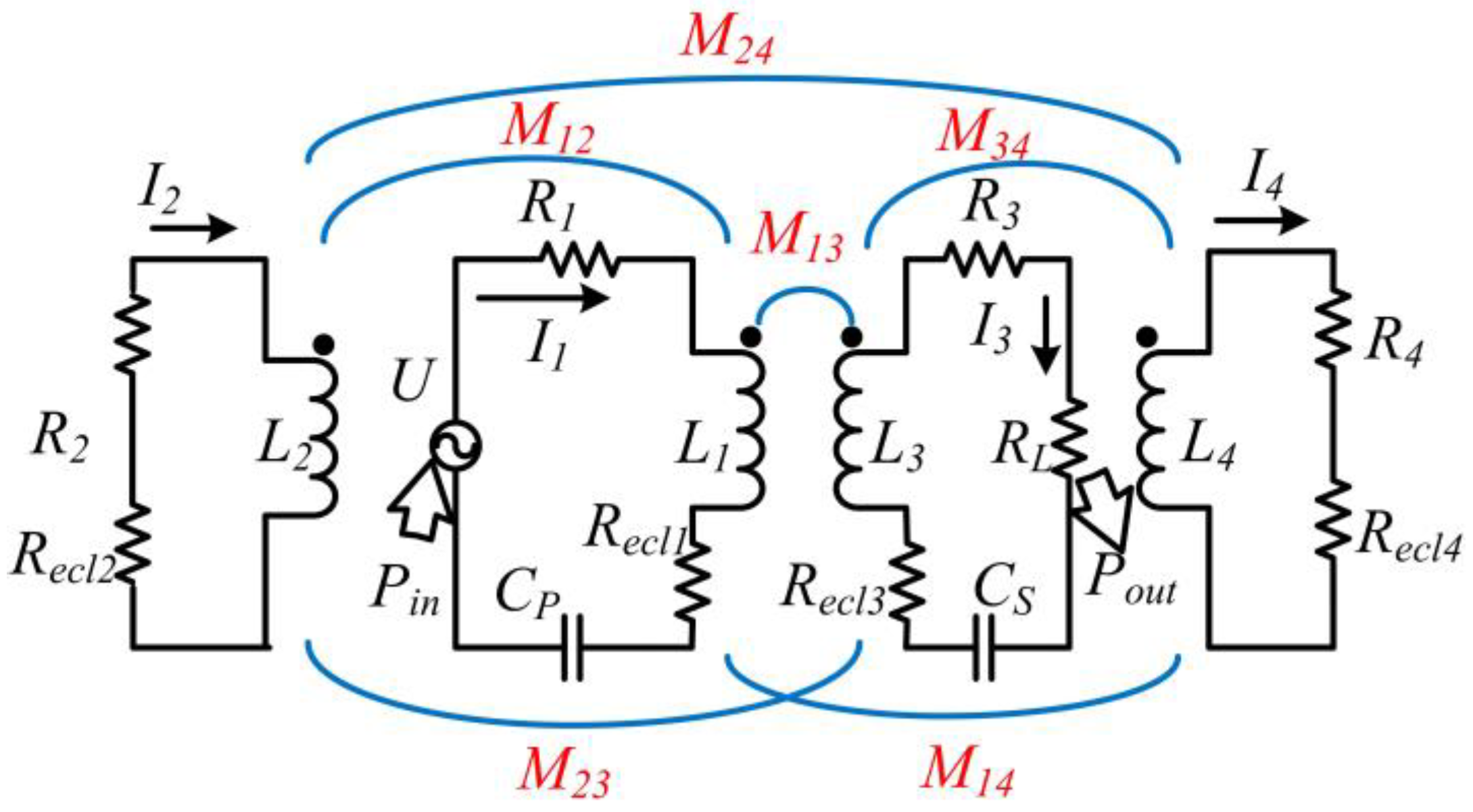
2. Circuit Model Analysis

It has been proved that both coupled-mode theory and circuit theory have the same analysis results in a steady state for midrange transfer distance [19], so we choose the circuit model in this paper. The series-series resonance structure is a kind of basic resonance structure and many other structures are from it, so we select it as the research target. In [20], it was stated that ECL is similar to the power loss from the resistance, so it can be transformed into Recl in the circuit models. Recl is a function of the coil structure, frequency, and the surroundings, so it is very similar to the ESR of the coil. The equivalent circuit model of the WPT systems with the structure we proposed is illustrated in Figure 3, where subscripts 1, 2, 3, and 4 denote the transmitter coil, primary shielding coil, receiver coil, and secondary shielding coil, respectively, L is the inductance, C is the compensation capacitances which series connected with main coils, U is the voltage source, R is the ESR of coils and the connection lines, RL means the equivalent load resistance, I denotes the current, M is the mutual inductance, Pin is the input power, and Pout is the output power.
We simplify the expressions of the impedance Z for the four circuit in order to analyze the circuit model easily, as:
{ Z 1 = ( R 1 + R e c l 1 + j ω L 1 + 1 / j ω C P ) / j ω Z 2 = ( R 2 + R e c l 2 + j ω L 2 ) / j ω Z 3 = ( R 3 + R e c l 3 + j ω L 3 + 1 / j ω C S + R L ) / j ω Z 4 = ( R 4 + R e c l 4 + j ω L 4 ) / j ω
From Figure 3, we can get the equivalent equations:
{ U = j ω ( Z 1 I 1 + M 12 I 2 + M 13 I 3 + M 14 I 4 ) 0 = j ω ( M 12 I 1 + Z 2 I 2 + M 23 I 3 + M 24 I 4 ) 0 = j ω ( M 13 I 1 + M 23 I 2 + Z 3 I 3 + M 34 I 4 ) 0 = j ω ( M 14 I 1 + M 24 I 2 + M 34 I 3 + Z 4 I 4 )
From Equation (2), we can get I2 and I4 expressed by I1 and I3.
I 2 = ( M 14 M 24 M 12 Z 4 ) I 1 + ( M 24 M 34 M 23 Z 4 ) I 3 Z 2 Z 4 M 24 2
I 4 = ( M 12 M 24 M 14 Z 2 ) I 1 + ( M 24 M 23 M 34 Z 2 ) I 3 Z 2 Z 4 M 24 2
Because the operating frequency is high, the modulus of the imaginary part is much larger than that of the real part of Z2, and Z4. R2, Recl2, R4, and Recl4 are assumed to be negligible, then we can get:
Z 2 = L 2 , Z 4 = L 4
From the definition of the coupling coefficient, we can get:
k x y = M x y / L x L y
Substituting (5) and (6) into (3) and (4), I3 can be obtained as:
I 3 = k 13 k 24 2 k 14 k 23 k 24 k 12 k 24 k 34 + k 12 k 23 + k 14 k 34 k 13 ( k 23 2 2 k 23 k 24 k 34 + k 34 2 ) L 3 + Z 3 ( k 24 2 1 ) · L 1 L 3 I 1
In order to make circuit 3 be in resonance condition, CS is selected as:
C P = 1 k 24 2 ( 1 k 12 2 k 14 2 k 24 2 + 2 k 12 k 14 k 24 ) ω 2 L 1
Substituting (8) into (3) and (4), we can get:
I 3 = j ω L 1 L 3 ( 1 k 24 2 ) ( R 3 + R L ) ( k 13 ( 1 k 24 2 ) k 12 ( k 23 k 24 k 34 ) k 14 ( k 34 k 23 k 24 ) ) I 1
I 2 = k 14 k 24 k 12 1 k 24 2 L 1 L 2 I 1 + k 24 k 34 k 23 1 k 24 2 L 3 L 2 I 3
I 4 = k 12 k 24 k 14 1 k 24 2 L 1 L 4 I 1 + k 23 k 24 k 34 1 k 24 2 L 3 L 4 I 3
Then we can get the reflection impedances of the Circuit 2, 3, and 4.
Z 13 = j ω M 13 I 3 I 1 = j ω k 13 L 1 L 3 I 3 I 1
Z 12 = j ω 0 M 12 I 2 I 1 = j ω L 1 k 12 ( k 14 k 24 k 12 ) 1 k 24 2 + j ω k 12 ( k 24 k 34 k 23 ) L 1 L 3 1 k 24 2 I 3 I 1
Z 14 = j ω 0 M 14 I 4 I 1 = j ω L 1 k 14 ( k 12 k 24 k 14 ) 1 k 24 2 + j ω k 14 ( k 23 k 24 k 34 ) L 1 L 3 1 k 24 2 I 3 I 1
From Equations (12)–(14) and (2), I1 can be calculated.
I 1 = U j ω Z 1 + Z 12 + Z 13 + Z 14
j ω Z 1 + Z 12 + Z 13 + Z 14 = R 1 + j ω L 1 + 1 / j ω C 1 + j ω L 1 L 3 I 3 I 1 ( k 12 ( k 24 k 34 k 23 ) 1 k 24 2 + k 13 + k 14 ( k 23 k 24 k 34 ) 1 k 24 2 ) + j ω L 1 ( 2 k 12 k 14 k 24 k 12 2 k 14 2 ) 1 k 24 2
Making circuit in resonance, we get:
C P = 1 k 24 2 ( 1 + 2 k 12 k 14 k 24 k 12 2 k 14 2 k 24 2 ) ω 2 L 1
In order to make the analysis easy, we define keq as follows, and then we can get the expression of Meq:
k e q = k 12 ( k 24 k 34 k 23 ) 1 k 24 2 + k 13 + k 14 ( k 23 k 24 k 34 ) 1 k 24 2
M e q = k e q L 1 L 3
When CP and CS are selected to meet the resonance condition, we can get the expressions of the current in circuit 1 and circuit 3.
I 1 = U ( R 3 + R e c l 3 + R L ) ( R 1 + R e c l 1 ) ( R 3 + R L + R e c l 3 ) + ω 2 M e q 2
I 3 = j ω M e q U ( R 3 + R L + R e c l 3 ) ( R 1 + R e c l 1 ) + ω 2 M e q 2
The input power Pin, output power Pout, and the transfer efficiency η can be calculated:
P i n = U I 1 = U 2 ( R 3 + R L + R e c l 3 ) ( R 1 + R e c l 1 ) ( R 3 + R e c l 3 + R L ) + ω 2 M e q 2
P o u t = R L I 3 2 = R L U 2 ω 2 M e q 2 ( ( R 1 + R e c l 1 ) ( R 3 + R e c l 3 + R L ) + ω 2 M e q 2 ) 2
η = P o u t P i n = R L R 3 + R L + R e c l 3 ω 2 M e q 2 ( R 1 + R e c l 1 ) ( R 3 + R e c l 3 + R L ) + ω 2 M e q 2
The equivalent circuit model of the WPT systems without the shielding coils is illustrated in Figure 4, where the subscripts T and R denote the transmitter coil and receiver coil, respectively, Pi is the input power, Po is the output power, and other parameters have the same meaning as that in Figure 3.
From the circuit model in Figure 4, we can get the equations:
{ U = ( j ω L T + 1 j ω C T + R T + R e c l T ) I T + j ω M T R I R 0 = ( j ω L R + 1 j ω C R + R R + R e c l R + R L ) I R + j ω M T R I T
CT and CP are selected to resonate with LT and LR at the angular frequency w, respectively.
ω = 1 L T C T = 1 L R C R
Combining (25) and (26), we can get the expressions of IT, IR:
I T = U ( R R + R L + R e c l R ) ( R T + R e c l T ) ( R R + R L + R e c l R ) + ω 2 M T R 2
I R = j ω M T R U ( R T + R e c l T ) ( R R + R L + R e c l R ) + ω 2 M T R 2
The input power, output power, and the transfer efficiency can be obtained as:
P i = U I T = U 2 ( R R + R L + R e c l R ) ( R T + R e c l T ) ( R R + R L + R e c l R ) + ω 2 M T R 2
P o = I R 2 R L = R L U 2 ω 2 M T R 2 ( ( R T + R e c l T ) ( R R + R L + R e c l R ) + ω 2 M T R 2 ) 2
η = R L R R + R L + R e c l R ω 2 M T R 2 ( R T + R e c l T ) ( R R + R L + R e c l R ) + ω 2 M T R 2
It can be seen from Equations (8), (17), and (26) that the coupling coefficients play critical roles in ensuring the system in resonance condition. From Equations (18) and (19), it is obvious that the shielding coils lower the equivalent mutual inductance. When comparing Equations (24) and (31), the difference between these systems is the ESR of power transmission coils and the equivalent mutual inductance. Additionally, we can learn that the efficiency increases with the increasing mutual inductance and decreasing ESR of the main coils.

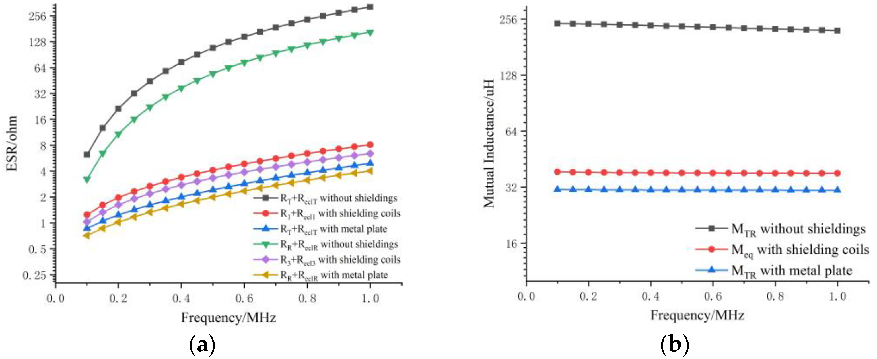
3. Simulations and Analysis

In Section 2, we analyzed the circuit model. We take advantage of FEA software Comsol 5.4 in order to get the parameters that are used in circuits. Besides, we can get the EMF distribution and evaluate the effects of the shielding coils or metallic plates. In this part, the analysis includes two parts that distinguished according to the shell material of AUV. For the reason that most of AUVs are slender-body of revolution, so the receiver coil is set at the AUV midcourse shown in Figure 1. The advantages of this structure are that the receiver coil is large and the mutual inductance is high. Besides, the structure has good rolling robustness and strength of structure. In this Section, the coils that we researched are built on the structure.

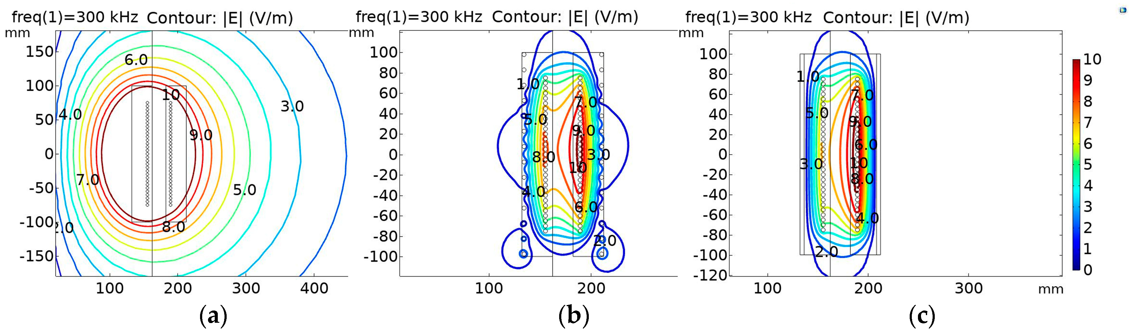
3.1. Nonmetallic Shell
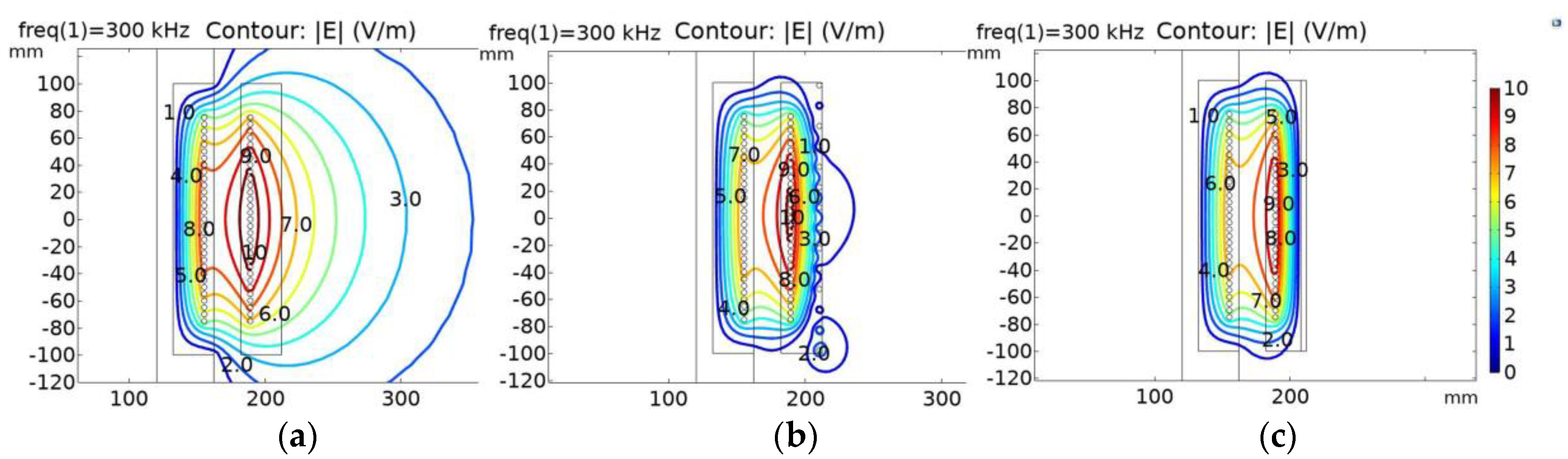
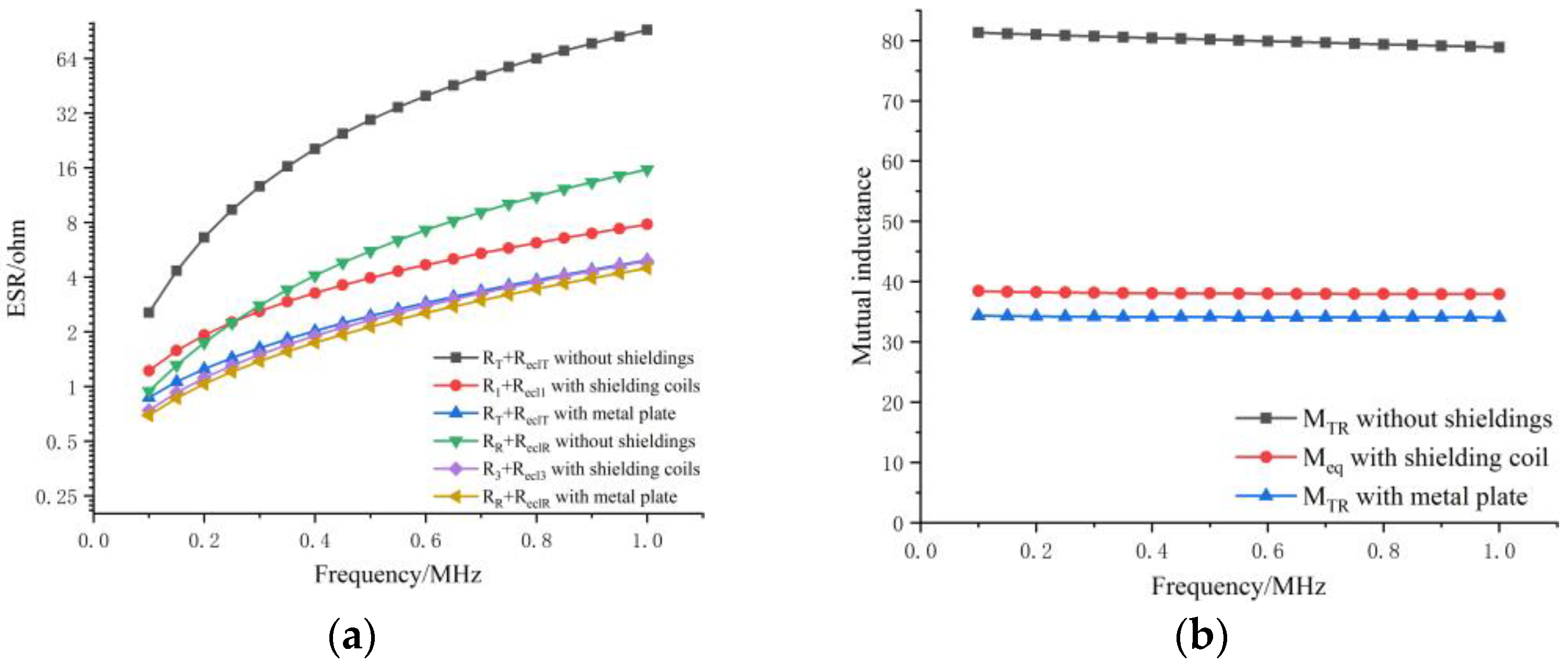
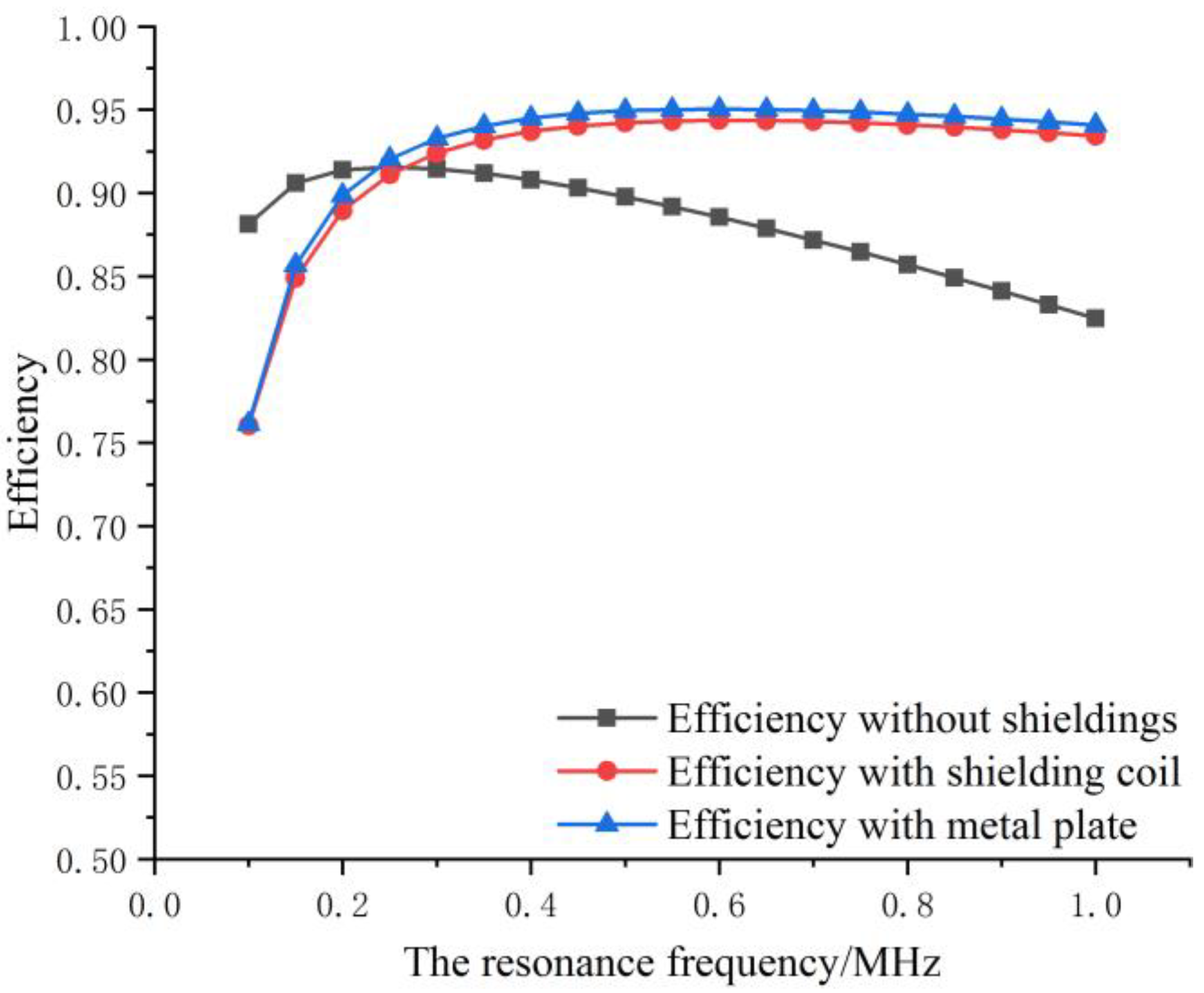
For the AUV with nonmetallic shell, the primary shielding coil is set at the outer space of the transmitter and the secondary shielding coil is set at the inner space of the receiver coil. For the reason that the electromagnetic properties of shell material are similar to air, we use air to replace it in simulations. Figure 5 illustrates the simulated geometric models. When we simulate the system with the shielding coils, we make Coil 2 and Coil 4 short and treat them as a part of loss medium, so the power loss from Coil 2 and Coil 4 no longer needs to be separately calculated. Therefore, we can get the inductance, resistance, and mutual inductance for the different structure of WPT systems. The parameters in simulations are listed in Table 1.
The thickness of metal plate is equal to the diameter of shielding coils, so we can get the mass of shielding coils and metal plates. By calculation, we can get the mass of shielding coils is 72.5% of that of metal plates when the coils are made of copper and the plates are made of aluminum. The mass of coils is 22.0% of that of metal plates if they are made of the same metal materials.
When the frequency is 300 kHz and RL is 100 ohms, both systems are in resonance condition and the output current is 1 A, we can get the electric field distribution, as shown in Figure 6.
From the simulation, it is shown that the shielding coils and aluminum alloy plates reduce electric field efficiently and the electric field is bound between coils and reduces the ECL in peripheral seawater. For the reason that the shielding coils are not fully symmetrically distributed, there are some circles in the bottom side in Figure 6b. Besides, we get the ESR and mutual inductance for the underwater WPT systems, the relationships between them, and the operating frequency in Figure 7.
From Figure 7, it is obvious that the ESR in the WPT system without shielding sharply increases with the increasing frequency. The ESR of the WPT system with shielding is slightly larger than that with a metallic plate. As for the mutual inductance, MTR without shielding is much higher than those of others and MTR with metallic plate is the least. In total, the ESR increases with an increasing frequency and the mutual inductances slowly decrease with the increasing frequency. Bring the results into Equations (24) and (31), we can get the relationship between the frequency and power transfer efficiency when the systems are in resonance condition.
From Figure 8, we can know that the highest efficiency for these systems is close. However, the power transfer efficiency of the system without shielding quickly decreases with the increasing resonance frequency. The efficiency for the systems with shielding coils or metallic plates grows with the increasing frequency first and then slowly decreases. The system with metal plates has a higher efficiency when the frequency is more than 200 kHz. The highest efficiency for the system with shielding coils is 1.5% lower than that of the system with metal plates. In total, the WPT system with metallic plates performs slightly better than the system with shielding coils when the frequency is more than 200 kHz. When considering the electric field, power transfer efficiency, the WPT systems with shielding coils have very good shielding effect and relatively high efficiency. The shielding coils are much lighter than metallic plate although the WPT system with metallic plate performs slightly better than the system with the shielding coil. The less weight means that AUV can carry more battery or the turn of receiver becomes larger. We propose the underwater WPT system with shielding coils when considering that the efficiency difference is small and the weight difference is large.

3.2. Metallic Shell

We just use one shielding coil in the primary side when considering that the metallic shell have the shield effect. Afterwards, we can obtain that M14, M24, and M34 are equal to zero in the circuit model that is shown in Figure 3. Being similar to the AUV, of which the shell is made of nonmetallic material, we make the simulations that are shown in Figure 9.
The thickness of metal plate is equal to the diameter of shielding coils, so we can get the same conclusion that the mass of shielding coils is 72.5% of that of metal plates when the coils are made of copper and the plates are made of aluminum. The mass of coils is 22.0% of that of metal plates if they are made of the same metal materials.
From the simulation, we can get the electric field distribution when RL = 100 ohms and the output current is 1 A. The simulation results show that the electric field is bound between coils or metallic plate under the case with shield. For the reason that the metallic shell can be treated symmetrically, but the shielding coil is not fully symmetrically distributed. The electric field is not also symmetrically distributed and there are some circles in the right bottom side in Figure 10b. The results for ESR and mutual inductance are similar to that of the AUV with nonmetallic shell, but the differences become less.
From Figure 11, we can learn that the ESR grows with frequency and that in the system without shield is largest. The ESR in the system with the shielding coil is larger than that in the system with the metal plate, but the difference in the receiver side is very small. MTR without shield is more than double of Meq or MTR with the meal plate. MTR and Meq slowly decrease with frequency and MTR with the metal plate is the least. Based on the ESR and mutual inductance, we can get the relationship between the power transfer efficiency and the resonance frequency illustrated in Figure 12.
From Figure 12, the power transfer efficiency increases with increasing resonance frequency first and it reaches the highest point. After that, the efficiency decreases slowly for the WPT systems with shielding. The maximum efficiency for the system with shield is higher than that without shield. When the frequency is higher than 300 kHz, the difference between the systems with and without shield becomes larger and larger. The difference value between the highest efficiency for the system with the metal plate and the system with the shielding coil is 0.7%. The system with the metal plate performs slightly better than the system with a shielding coil. However, the shielding coil is lighter than the metal plate.
From Figure 6, Figure 8, Figure 10, and Figure 12, we can learn that the underwater WPT systems with shielding coils perform better than that without a shield when the operating frequency is relatively high. The highest efficiency point appears in a lower frequency band for the system without a shield. When the AUV is made of aluminum alloy, the highest efficiency for the system with shielding coils is higher than that without a shield. The metal plate and shielding coils have almost the same influence on the underwater system in electric field distribution and power transfer efficiency. The metal plate can be treated as shielding coils with lots of turn, so they are kind of equivalent. The system with shielding coils is more attractive when considering that the differences are small and the shielding coils are much lighter than metallic plate. Besides, the size of coils is very small and the coils are easy to make, so it is worth introducing the shielding coils into the underwater WPT system.

4. Conclusions

In this paper, we analyzed the circuit model of the underwater WPT systems with and without the shielding coils and got the expression of the compensation capacitances. The shielding coils downgraded the equivalent mutual inductance and they played an important role in the power transfer efficiency. Besides, we adopted the FEA to get the distribution of EMF and the relationship between the ESR of coils and the resonance frequency. From the relationship between the efficiency and frequency, it was found that the shielding coils could improve the efficiency when the AUV is made of aluminum alloy and its maximum efficiency is higher than the system without the shielding coils. When compared with system with the metal plate, the shielding coils almost have the same influence on the underwater system in the electric field distribution and power transfer efficiency. It is worth introducing the shielding coils into the underwater WPT system while considering that the differences are small and the shielding coils are much lighter than the metallic plate.

Author Contributions

Y.W. conceived the study and wrote the manuscript; B.S. and Z.M. analyzed the theoretical results and reviewed the manuscript.

Acknowledgments

This research was supported by National Science Foundation of China (Grant No.: 51179159; 61572404) and the Shaanxi Province Youth Science and Technology New Star Project (Grant No.2016KJXX-57).

Conflicts of Interest

The authors declare no conflict of interest.

References

  1. Ahmed, A.M.E.; Duan, W.-Y. Overview on the Development of Autonomous Underwater Vehicles. (AUVs). J. Ship Mech. 2016, 768–787. [Google Scholar] [CrossRef]
  2. Li, Y.; Jiang, Y.; Cao, J.; Wang, B.; Li, Y. AUV docking experiments based on vision positioning using two cameras. Ocean Eng. 2015, 110, 163–173. [Google Scholar] [CrossRef]
  3. Wu, L.; Li, Y.; Su, S.; Yan, P.; Qin, Y. Hydrodynamic analysis of AUV underwater docking with a cone-shaped dock under ocean currents. Ocean Eng. 2014, 85, 110–126. [Google Scholar] [CrossRef]
  4. Zhang, T.; Li, D.; Yang, C. Study on impact process of AUV underwater docking with a cone-shaped dock. Ocean Eng. 2017, 130, 176–187. [Google Scholar] [CrossRef]
  5. Vincent, D.; Sang, P.H.; Williamson, S.S. Feasibility study of hybrid inductive and capacitive wireless power transfer for future transportation. In Proceedings of the 2017 IEEE Transportation Electrification Conference and Expo (ITEC), Chicago, IL, USA, 22–24 June 2017. [Google Scholar]
  6. Guo, Y.; Wang, L.; Zhang, J.; Zhang, Y.; Zhang, Y. A Research on Characteristics of Dynamic Wireless Charging System for Electric Vehicles. Qiche Gongcheng/Automot. Eng. 2017, 39, 642–647. [Google Scholar]
  7. Lu, M. Synergetic Attenuation of Stray Magnetic Field in Inductive Power Transfer. Ph.D. Thesis, Virginia Polytechnic Institute, Blacksburg, VA, USA, 2017. [Google Scholar]
  8. Le, K.; Yuli, H.U.; Wei, Z. Maximum power efficiency tracking on underwater magnetic resonant wireless power transfer system. Harbin Gongcheng Daxue Xuebao/J. Harbin Eng. Univ. 2017, 38, 829–835. [Google Scholar]
  9. Yan, Z.; Zhang, Y.; Song, B.; Zhang, K.; Kan, T.; Mi, C. An LCC-P Compensated Wireless Power Transfer System with a Constant Current Output and Reduced Receiver Size. Energies 2019, 12, 172. [Google Scholar] [CrossRef]
  10. Lin, M.; Li, D.; Yang, C. Design of an ICPT system for battery charging applied to underwater docking systems. Ocean Eng. 2017, 145, 373–381. [Google Scholar] [CrossRef]
  11. Kan, T.; Mai, R.; Mercier, P.P.; Mi, C.C. Design and Analysis of a Three-Phase Wireless Charging System for Lightweight Autonomous Underwater Vehicles. IEEE Trans. Power Electron. 2018, 33, 6622–6632. [Google Scholar] [CrossRef]
  12. Yan, Z.; Zhang, Y.; Kan, T.; Lu, F.; Zhang, K.; Song, B.; Mi, C.C. Frequency Optimization of a Loosely Coupled Underwater Wireless Power Transfer System Considering Eddy Current Loss. IEEE Trans. Ind. Electron. 2018, 66, 3468–3476. [Google Scholar] [CrossRef]
  13. Zhang, K.; Zhang, X.; Zhu, Z.; Yan, Z.; Member, S.; Song, B.; Mi, C.C. A New Coil Structure to Reduce Eddy Current Loss of WPT Systems for Underwater Vehicles. IEEE Trans. Veh. Technol. 2019, 68, 245–253. [Google Scholar] [CrossRef]
  14. Lee, I.G.; Kim, N.; Cho, I.K.; Hong, I.P. Design of a Patterned Soft Magnetic Structure to Reduce Magnetic Flux Leakage of Magnetic Induction Wireless Power Transfer Systems. IEEE Trans. Electromagn. Compat. 2017, 59, 1856–1863. [Google Scholar] [CrossRef]
  15. Yan, Z.; Song, B.; Zhang, K.; Wen, H.; Mao, Z.; Hu, Y. Eddy current loss analysis of underwater wireless power transfer systems with misalignments. AIP Adv. 2018, 8, 101421. [Google Scholar] [CrossRef] [Green Version]
  16. Yang, C.L.; Chang, C.K.; Lee, S.Y.; Chang, S.J.; Chiou, L.Y. Efficient four-coil wireless power transfer for deep brain stimulation. IEEE Trans. Microw. Theory Tech. 2017, 65, 2496–2507. [Google Scholar] [CrossRef]
  17. Zhang, J.; Yuan, X.; Wang, C.; He, Y. Comparative Analysis of Two-Coil and Three-Coil Structures for Wireless Power Transfer. IEEE Trans. Power Electron. 2016, 32, 341–352. [Google Scholar] [CrossRef]
  18. Nguyen, V.T.; Kang, S.H.; Choi, J.H.; Chang, W.J. Magnetic resonance wireless power transfer using three-coil system with single planar receiver for laptop applications. IEEE Trans. Consum. Electron. 2015, 61, 160–166. [Google Scholar] [CrossRef]
  19. Kiani, M.; Ghovanloo, M. The Circuit Theory Behind Coupled-Mode Magnetic Resonance-Based Wireless Power Transmission. IEEE Trans. Circuits Syst. I Regul. Pap. 2012, 59, 2065–2074. [Google Scholar] [CrossRef] [PubMed]
  20. Zhang, K.; Zhu, Z.; Du, L.; Song, B. Eddy Loss Analysis and Parameter Optimization of the WPT System in Seawater. J. Power Electron. 2018, 18, 778–788. [Google Scholar]
Figure 1. The example of wireless power transfer (WPT) system for autonomous underwater vehicles (AUV).
Jmse 07 00267 g001
Figure 2. The schematic diagram of shielding coil working principle.
Jmse 07 00267 g002
Figure 3. The equivalent circuit model of the underwater WPT system with two shielding coils.
Jmse 07 00267 g003
Figure 4. The equivalent circuit model of underwater WPT system without shielding coils.
Jmse 07 00267 g004
Figure 5. Simulation geometric models for WPT systems where the blue purple area means seawater, gray area is air, the white is aluminum alloy plate, coils are made of copper and the red lines are the rotary axis. (a) The underwater WPT system without shield. (b) The underwater WPT system with shielding coils. (c) The underwater WPT system with metallic plates as shield.
Jmse 07 00267 g005
Figure 6. The distribution of electric field: (a) the system without shield; (b) the system with shielding coils; (c) the system with metallic plate as shield.
Jmse 07 00267 g006
Figure 7. The relation between ESR of coils, the equivalent mutual inductance between coils and the work frequency. (a) ESR of coils change with frequency for three structure WPT system. (b) The mutual inductances change with frequency for three structure WPT system.
Jmse 07 00267 g007
Figure 8. The power transmission efficiency changes with the resonance frequency.
Jmse 07 00267 g008
Figure 9. Simulation geometric models for WPT system. The blue purple area means seawater, gray area is air, the white area is aluminum alloy plate, coils are made of copper and the red lines are the rotary axis. (a) The underwater WPT system without shield. (b) The underwater WPT system with a shielding coil. (c) The underwater WPT system with metallic plate as shield.
Jmse 07 00267 g009
Figure 10. The distribution of the electric field: (a) the system without shield; (b) the system with a shielding coil; and, (c) the system with a metallic plate as shield.
Jmse 07 00267 g010
Figure 11. The relation between equivalent series resistance (ESR) of coils, the equivalent mutual inductance between coils and the work frequency. (a) ESR of coils change with frequency for three structure WPT system. (b) The mutual inductances change with frequency for three structure WPT system.
Jmse 07 00267 g011
Figure 12. The power transmission efficiency changes with the resonance frequency.
Jmse 07 00267 g012
Table 1. The meanings and value of parameters in the simulation.
SymbolQuantityValue
rlineRadius of line/mm2
R1, R2, R3, R4Radius of coils 1, 2, 3 and 4/mm189, 210, 155, 134
nT and nRTurns of transmitter and receiver31
Nshielding coilTurns of shielding coils14
dDistance between two adjacent power transmission coils/mm5
dshielding coilDistance between two adjacent shielding coils/mm15
μseawater, μcopper, μair, μaluminum,Relative permeability for seawater, copper, air, aluminum1, 0.99990, 1, 1.00002
σseawater, σcopper, σair, σaluminum,Conductivity for seawater, copper, air, aluminum/(S/m)4.5, 5.998 × 10⁷, 0, 3.77 × 10⁷
εseawater, εcopper, εair, εaluminum,Relative permittivity for seawater, copper, air, aluminum81, 1, 1, 1
ρcopper, ρaluminumDensity for copper, aluminum/(kg/m3)8.9 × 103, 2.7 × 10³

