1. Introduction
Offshore wind power for energy supply has become popular in recent years. This is in view of its stability in response to sea wind combined with the high efficiency of generating electrical power. According to the Global Wind Power Development Outlook Report 2016 reported by the Global Wind Energy Council, the capacity of offshore wind turbines in the world had increased by 2219 MW in the year 2016, 15.5% of the total capacity of offshore wind turbines installed in 2014. This trend showed the increasing installation of offshore wind turbines for energy supply over the years.
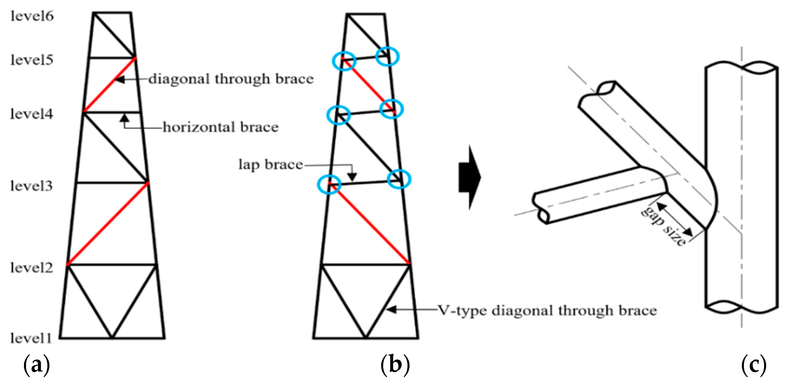
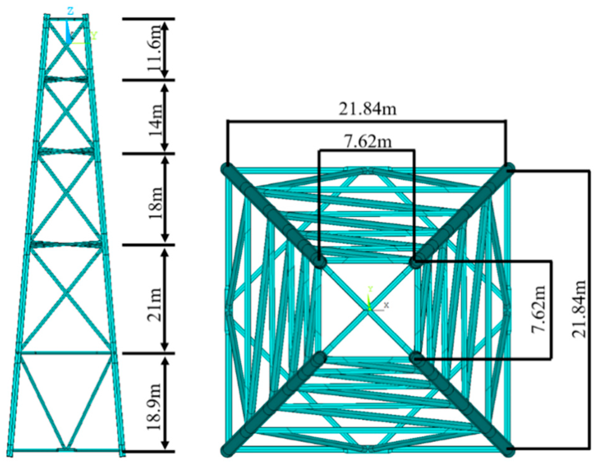
In the current study, a jacket substructure of the K-type vertical framing is selected for offshore wind turbines installed at a water depth of 30 m–70 m. Despite that research work of tubular joints with a complete overlap of braces has been conducted intensively, the scope, however, is only limited to the investigation of a joint subjected to lap brace loading, as shown in
Figure 1. The research for the behavior of complete jacket substructure with completely overlapped joints is yet to be examined.
The concept of the eccentric jacket substructure using completely overlapped joints was first proposed by Cheung et al. [
1]. Their study showed that the eccentric jacket attained the advantages of saving material and shorter construction time in comparison to conventional jacket structures. The experimental study by Fung et al. [
2,
3] concluded that the ultimate capacity of the completely overlapped joints under lap brace axial compression was higher than that of the gap joint. The joint behavior was significantly affected by the geometrical parameters of the braces. For example, when the gap size (as shown is
Figure 1c) between the lap brace and the external chord surface is smaller, the bending of the chord and the plasticization of the diagonal through-brace results in joint failure, and the lap brace yield becomes the main failure as the gap size increases. The study by Soh et al. [
4] concluded that the local buckling of the braces of completely overlapped joint was the main energy-dissipating device. It was further commented that increasing the lap brace diameter could improve the joint hysteresis performance. However, the influences of gap size and the through-brace wall thickness were found to have a minimum impact on joint behavior.
The parametric equations to predict the stress concentration factors (SCF) of completely overlapped joints proposed by Gho et al. [
5] and Gao et al. [
6] revealed that the SCF was significantly influenced by the brace wall thickness and the gap size of the short segment of the diagonal through-brace joining the chord face. Gho et al. [
7] further conducted an experimental investigation to study in detail the stress and strain concentration of completely overlapped joints under combined load cases that consisted of axial load (AX), in-plane bending (IPB) and out-plane bending (OPB). Their results indicated that the maximum strain concentration was located at the region between the two braces for the case of the joint under AX and OPB. On the other hand, for the case of the joint under IPB, it was located at the crown of the lap brace. The peak hot spot stress was found to occur at the position between the saddle and the crown for the joint under combined load cases. Four possible failure modes of joints under lap brace axial compression were proposed by Gho et al. [
8], namely the through-brace wall plasticization, the lap brace yielding, the lap brace local buckling, and the lap brace failure.
The parametric equations to calculate the ultimate strength of the completely overlapped joint proposed by Gho et al. [
9] commented that the ultimate joint strength increased with the reduced gap size. The study of local joint flexibility (LJF) by Gho [
10] concluded that the load from the lap brace transferred to the chord could be by beam action, shell bending, or a combination of these actions. However, the gap size of the short segment of the diagonal through-brace affected the LJF significantly. The parametric equations to predict LJF of the completely overlapped joint under basic loading by Gao et al. [
11,
12,
13] suggested some approaches of reducing the joint LJF. The investigation on the seismic behavior of the completely overlapped joints under fire by Liu et al. [
14] concluded that the local buckling at the intersection of the two braces was the main mechanism to dissipate energy. However, the performance of the joint was found poorer with increasing temperature. Zhou et al. [
15,
16] studied the simplified analysis models for jacket structures.
Despite the merits of using eccentric jacket substructure for offshore wind turbines highlighted by Gho and Yang at a conference 2017, there was no further research work done specifically for this joint type, and no research information at all for the strength performance of the eccentric jacket substructure with completely overlapped tubular joints. Most research work done of this joint configuration is confined to uni-planar tubular joints subject to lap brace axial compression or bending. Thus in this paper, the structural performance and characteristics of the stress distribution of the eccentric jacket substructure is assessed with reference to the existing traditional jacket substructure.
3. Boundary Conditions and Load Cases
The base of the four legs of the jacket substructure was assumed pinned. To simulate the actual condition on -ite, the weights of the topside structure and equipment acting at the top level of the jacket substructure were applied as vertical downward loads F
Z. The horizontal environment loads were simplified as static loads F
H and were applied horizontally at the top level of the jacket legs. The applied vertical and horizontal loads, F
Z and F
H acting on each jacket leg were 1, 350 kN, and 135 kN, respectively. In view of the rotation symmetry of the jacket substructure, the horizontal load was applied at four different horizontal angles at 0, 15, 30, and 45 degrees, as illustrated in
Figure 4. There were four combined load cases of F
Z and F
H, namely load cases #1 to #4, in 0, 15, 30, and 45-degree directions, respectively.
4. Results and Discussions
The ultimate strength, the stress distribution, and the location of high stress areas of the joints of the traditional and the eccentric jacket substructures were closely examined. The influences of the dimensionless parameter ξ on the strength performance of the joints of the two jacket substructures were also presented. However, in the current study, only the joints at levels 3 to 5 of the eccentric jacket substructure, which were comprised of completely overlapped joints, were investigated.
4.1. Ultimate Strength
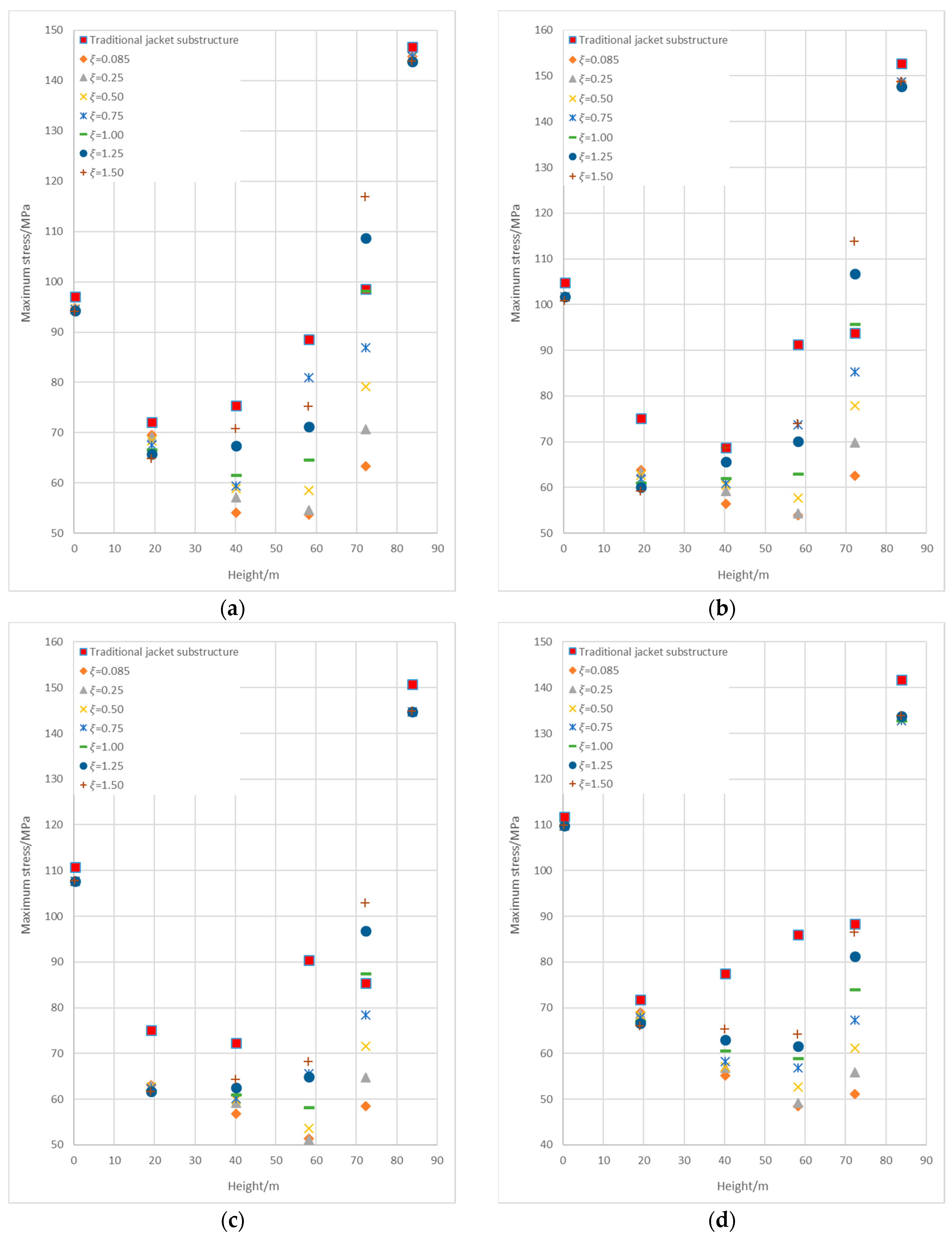
The comparison of the maximum equivalent stress at each level of the traditional and the eccentric jacket substructures under the four load cases are shown in
Figure 5. For both the traditional and eccentric jacket substructures, the maximum stresses at levels 1 and 6 were much greater than that of the other levels. The high load magnitudes at these two levels were not unexpected due to the effect of the boundary condition and load application.
For the effect of dimensionless parameter
ξ, at 0.085, the comparison of the ultimate strength between the traditional and the eccentric jacket substructure showed that the differences of stresses at levels 1 and 6 were small. Note that the joints and the structural configurations at these two levels of the jacket substructures were identical. However, the maximum stresses at levels 3 to 5 of the eccentric jacket substructure were found lower than that of the traditional jacket structure, as presented in
Table 2.
The ultimate strength of the eccentric jacket substructure with the horizontal load applied at 45 degrees yielded the highest value among all the load cases. The reduction of the maximum stress of the joints at level 2 was minimum. In view of the geometrical configuration of the joints, the eccentric jacket substructure with completely overlapped joints showed a lower maximum stress than the traditional jacket substructure with simple gap joints.
The study on the effect of the gap size of the short segment of the through-brace joining the chord face revealed that the maximum stresses at levels 3 to 5 increase dwith ξ. As shown in
Figure 5a,b, the maximum stress at level 5 of the eccentric jacket substructure was higher than that of the traditional jacket substructure when ξ was greater than 1. It could, therefore, be commented from the results that the dimensionless parameter ξ should be controlled with a gap size not greater than the through-brace diameter for better ultimate strength at the joint.
4.2. Stress Distribution of Joints and Lap Brace Member
(1) Stress distribution of joints at the same elevation
The load’s distribution of the four joints at the same level of the eccentric or traditional jacket substructure are not even as well as the stress distribution. The comparison of the difference of the maximum equivalent stress at each elevation of levels 3 to 5 of the eccentric and traditional jacket substructure under the four load cases are shown in
Figure 6. The ordinate "Difference in maximum stress" represents the difference in maximum equivalent stress between the highest and lowest stress joints (at each level). The smaller difference means that the load’s distribution of four joints at this level are more even.
As presented in
Table 3, the differences in maximum stress at minimum ξ (0.085 with a gap size of 51 mm) at level 3 to 5 of the eccentric jacket were found greatly reduced in comparison to that of the traditional jacket substructure.
The reduction of stress differences of the eccentric jacket demonstrated that the maximum stresses of the joints at the same elevation are closer. It could be commented from the structural configuration that the eccentric jacket could have better material saving with full utilization of the members than that of the traditional jacket substructure.
Moreover, the difference in maximum stress at level 3 decreases with increasing ξ. The changes of stresses; however, were found less at levels 4 and 5. Generally speaking, for the eccentric jacket with ξ in a range of 0.085 to 1.5, the difference in maximum stress at each level was much less than that of the traditional jacket substructure.
(2) Stress distribution of horizontal members
The comparison of the maximum stresses of the lap braces (eccentric jacket) and the horizontal braces (traditional jacket) at levels 3 to 5 under the four load cases are shown in
Figure 7. The maximum stresses of the horizontal members at a minimum
ξ (0.085 with a gap size of 51 mm) are presented in
Table 4.
The increment of the maximum stress of the lap braces of the eccentric jacket substructure was still within the designed yield strength of the material. This was expected as the applied load was effectively and directly transferred between the lap brace and the diagonal through-braces at the joint without passing through the chord face (jacket leg). This reduced the stress on the chord as a primary member of the structure and, thus, enhanced the ultimate strength of the joint. The impact of the dimensionless parameter ξ on the maximum stress of the lap brace could be significant—the tilt angle of the lap brace increases, and thus the stress, with ξ.
4.3. Location of the High-Stress Area
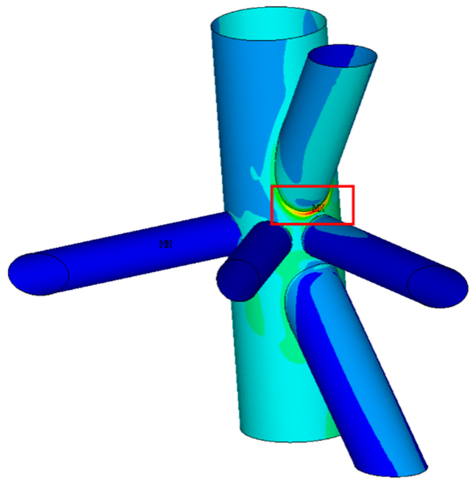
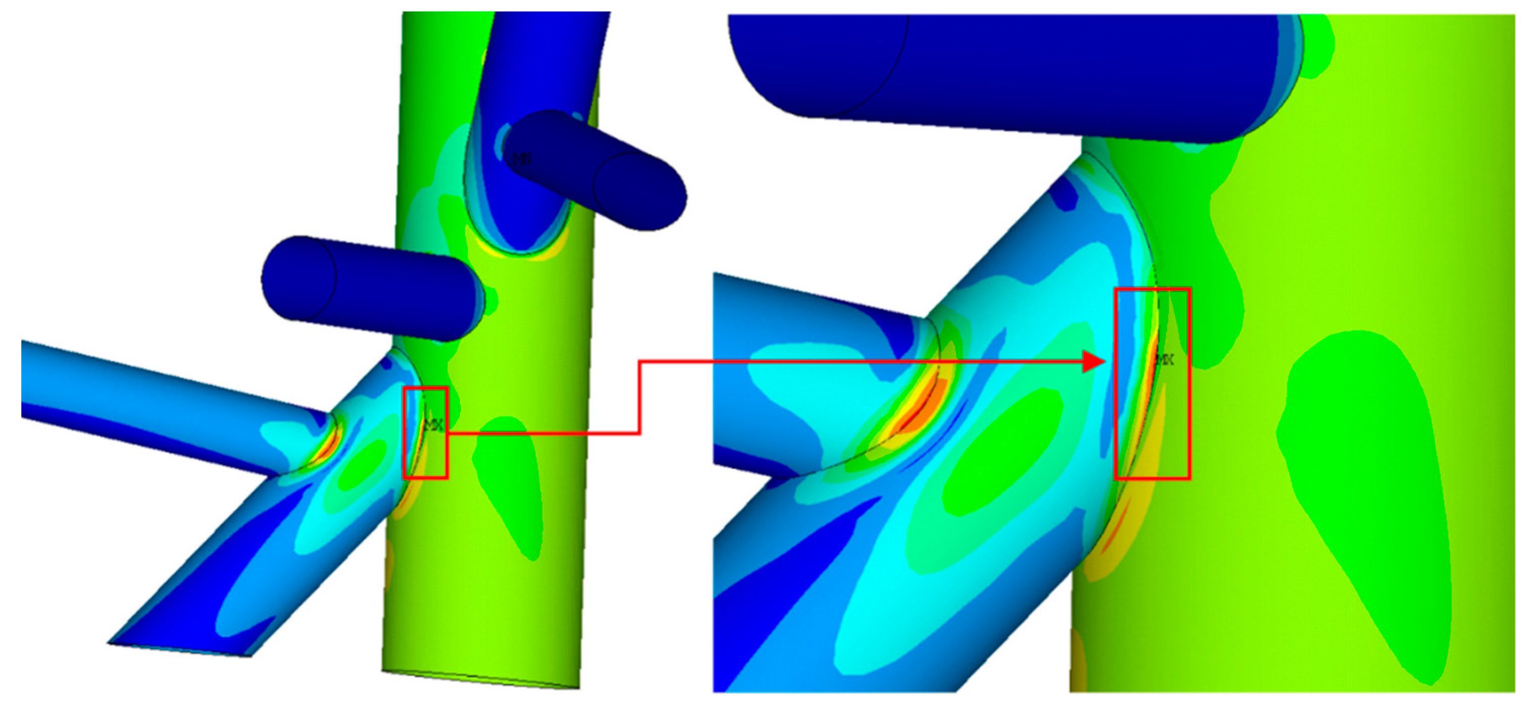
The high-stress critical areas of the two jacket substructures occurred at different locations. For the traditional jacket, it was located on the chord face of the legs at the gap intersection between the two braces, as shown in
Figure 8. On the other hand, for the eccentric jacket substructure with minimum
ξ (0.085 with gap size of 51 mm) at the joint, there were three possible locations of high-stress area on the chord face of the jacket legs (similar to that of the traditional jacket substructure), the short segment of the diagonal through-brace or the end of the diagonal brace joining the chord face, as depicted in
Figure 9,
Figure 10,
Figure 11 and
Figure 12, respectively. However, most of the high stress area of the joints of the eccentric jacket substructure occurred at the short segment of the diagonal through brace joining the chord face.
In comparison with the joints of traditional jacket, the joints of eccentric jacket substructure subjected to smaller stress on the chord face of the jacket leg, which indicated that most of the load components were directly transferred among the braces without passing via the chord face, thus enhancing the joint’s ultimate capacity. This result was inconsistent with the conclusion made by other researchers for the study of joints with complete overlap of braces, where the short segment of the diagonal through-brace dissipated most of the energy under cyclic loading and reduced the stress concentration on the chord face than the simple gap joints [
4].
For the joints independent of ξ, the high stress area was located on the chord face of the jacket leg. However, the location of the high-stress area could gradually be transferred from the end or the short segment of the diagonal through-brace to the joint intersection of the lap brace and diagonal through-brace with increasing ξ. The behavior of this load transfer mechanism of the joint with a complete overlap of braces occurred at ξ greater than 1.
5. Conclusions
An eccentric jacket substructure is comprised of completely overlapped joints. The comparison of the ultimate strength between the eccentric and the traditional jacket substructure revealed that the maximum stress at each level of the eccentric jacket could be reduced significantly, as high as 20 to 40% substructure. For the eccentric jacket, the difference in the maximum stress of the four joints at the same elevation could be reduced by 41 to 84%.
The lap brace of the eccentric jacket plays a significant role than the horizontal braces of the traditional jacket substructure. It could be seen from the increment of the maximum stress by 78 to 137%. There is a need to highlight that for the completely overlapped joint, loads are being transferred directly between the lap brace and the diagonal through brace. For the traditional jacket substructure, the high-stress area is located on the chord face of the jacket leg. On the other hand, for the eccentric jacket substructure most of the high-stress area occurred at the short segment of the diagonal through brace joining the chord face. This indirectly indicates that the joints of the eccentric jacket substructure would have higher ultimate strength, where the wall thickness of the chord could be reduced for cost-saving of material.
In the parametric study, the load ratios of the joints at the same elevation are less affected by the dimensionless parameter ξ. However, the ultimate strength of the joint of the eccentric jacket substructure reduces with increasing ξ. At relatively large ξ, the maximum stress of the lap brace increases, and the location of high-stress area transferred from the short segment of the diagonal through-brace to the joint intersection of the lap brace and diagonal brace. The findings presented in this paper are also in good agreement with the conclusions made by other researchers based on the study of the completely overlapped joints isolated from the frame structure and tested under lap brace axial compression and cyclic loading.


