1. Introduction
Post-pressure grouting is an effective method to improve bearing capacity of bored piles. It has been a common practice when the piles are designed to carry a significant end-bearing load. With the help of a high-pressure pump, the prepared grout is injected into the soil layer at the level of the pile base, compacting, permeating, and fracturing the surrounding soils to strengthen them. In the meantime, the grout also penetrates upward a certain distance along the shaft–soil interface. The migration of the grout along the pile shaft is regarded as an important mechanism responsible for the improvement of the pile capacity [
1,
2]. Research into the penetration height of the grout is of great important in evaluating the behavior of grouted piles.
The improvement effect of base grouting on the side friction has been proved by extensive field monitoring data, which show that the post-grouted piles achieve higher side friction than the non-grouted ones [
2,
3,
4,
5,
6,
7,
8]. In routine practice, the penetration height of the grout from the pile base is regarded as the reinforcement height of the side friction [
9]. Even though the penetration height of the grout plays a significant role in predicting the side friction of the grouted piles, there is limited study of the penetration height. The determination of the parameter was mostly based on personal experience. Observations in the field have shown that cement grout penetrates upward along the sides of the drilled pile over a distance of about 10 to 15 m [
10]. Occasionally, the grout can penetrate upward more than 70 m to the ground surface [
9]. The Chinese design codes provide a recommended height of 12 m for practical purposes, which is a very conservative estimate. Considering the difference in engineering geological conditions, entirely empirical method will introduce significant uncertainties. Therefore, it is desirable to develop a well-established rational design methodology for the prediction of grouting penetration height.
In this paper, a prediction method of grouting penetration height along the shaft of base grouted pile was proposed. Considering the balance and losses of the grout pressure during grouting, an iterative procedure was given to determine the penetration height of the grout in layered soils. Field test results were also provided to indicate the validity of the proposed method.
2. Penetration Criterion
With the help of a high-pressure pump, the prepared cement grout was injected into the soil layer near the pile base through grout pipes connected to the reinforcement bars of the pile during construction. At the initial stage of grouting, the grout permeates into the soil pores or pushes the soil outward forming a grout bodies with a smooth flow of the grout. With the clogging up of pore channels or densification of the soil, grouting pressure increases gradually until it builds up to a threshold fracturing pressure and the grout intrudes into a weakness plane between the pile and soil to develop grout-filled fractures.
The threshold fracturing pressure that must be exceeded before penetration begins cannot be obtained accurately. It depends upon various parameters linked to the grout characteristics and the properties of surrounding soil around the pile base [
11,
12,
13,
14]. In general cases, it is larger than the lateral normal stress acted on the pile side at the level of pile base [
15]. Additionally, as the grout will intrude into the pile–soil interface more easily than fracture the surrounding soils, the threshold fracturing pressure should be less than the soil fracture pressure.
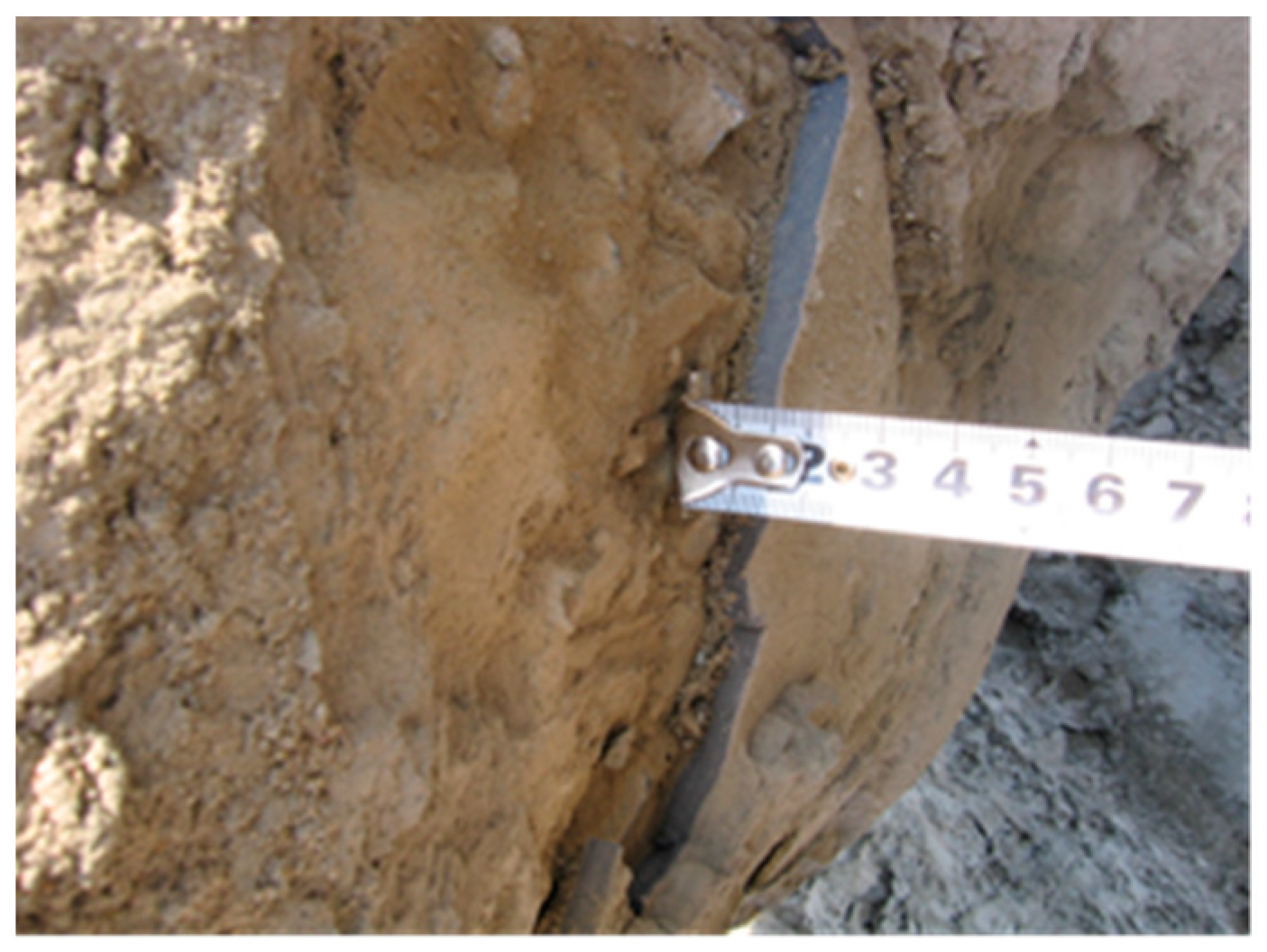
Under the grouting pressure at the pile base, the grout will travel alongside the shaft of the pile until a pressure balance achieved or grouting terminated. If the pressure gradient is not sufficient enough to overcome the friction from the flowing grout, the flow will stop. A cement layer can be formed around the pile shaft after curing, as shown in
Figure 1.
3. Grouting Penetration Model
To evaluate the grouting penetration height along the shaft of the pile, a model is proposed to study the flow properties of the grout. Unlike the fracture grouting in the soil, the grout penetrates along a certain path, i.e., the pile–soil interface [
13,
16].
Cement grout can be described as a Bingham fluid [
17,
18]. The rheological properties can be described as
where
is the shear stress,
is static shear stress,
is the viscosity of the grout, and
is the shear rate of the grout.
Grout flows upward between the pile–soil interfaces under the grouting pressure. As shown in
Figure 2, a small annular element, with length of
dL and width of 2
u was taken from the grout to consider the equilibrium conditions. An equation can be obtained as
where
is the radius of the pile.
is the radius of the pile hole squeezed by the grout.
is the grouting pressure, which changes with
along the height.
is the unit weight of the cement grout.
Substituting Equation (1) into Equation (2),
For Bingham fluids, it behaves as a rigid body if the shear stress is less than the yield stress (
). As shown in
Figure 2, the stress exceeds the yield stress only for
There is no flow if
is greater than
. Integration of Equation (5), with
at
,
Integration of Equation (5) to obtain the flow rate, gives
The driving pressure at the front of the propagating grout decreases gradually with the increases in the grout flow resistance. When the driving pressure is less than the lateral normal stress acted on the pile side, the grout cannot penetrate further into pile-soil interface. Penetration is stopped due to equilibrium between the driving and resistance forces. The minimum driving pressure for penetration can be approximated by the lateral normal stress acted on the pile side as follows,
where
is the lateral earth pressure coefficient.
is the mean unit weight of the soil layer above the penetration height.
is the pile length.
is the penetration height of the grout.
The pressure gradient of the flowing grout between the pile and the soil can be written as
where
is the grouting pressure at the pile base.
Substituting Equation (10) into Equation (8),
The penetration height of the grout can be estimated through the Equation (11) if the grouting pressure at the pile base and the flow rate of the grout can be measured.
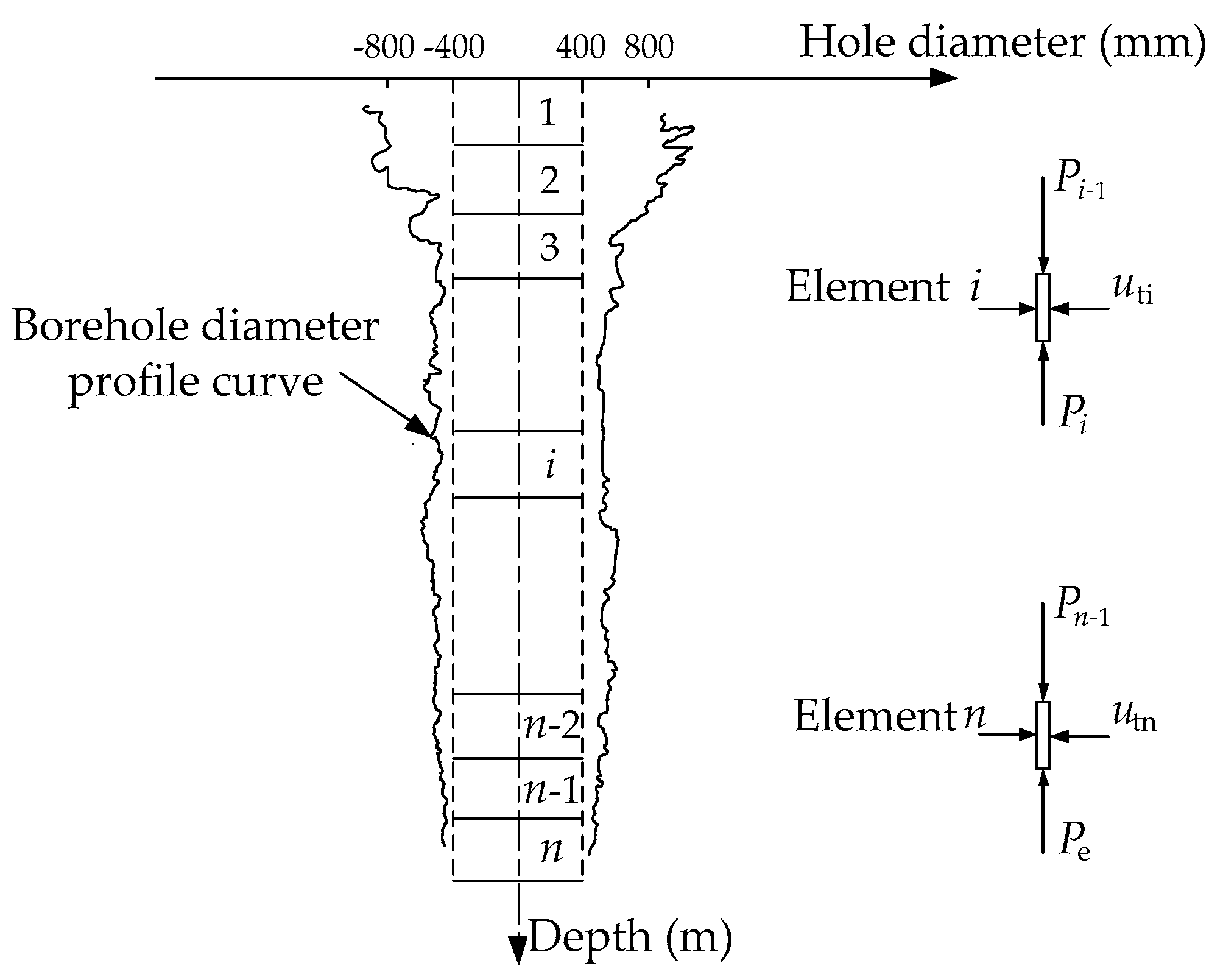
In practice, considering the surface of drilled pile was irregular due to the instability of the drill hole during construction, as schematically shown in
Figure 3 [
19]. The grout flows along a rough wall of tube plane, rather than an idealized smooth wall of tube plane as shown in
Figure 2. The penetration height of the grout will decrease and a reduction factor
should be applied for the calculated height using Equation (11) to account for the borehole roughness. The reduction factor can be defined as the ratio of the pile length to the measured mean length of borehole diameter profile curve of the pile (as shown in
Figure 3).
where
is the mean length of borehole diameter profile curve of the pile.
Then, the penetration height of the grout can be corrected as
4. Iterative Procedure of Grouting Penetration Height in Layered Soil
In practical engineering, the foundation soil is layered rather than homogeneous. The various modulus of the soil will result in the difference in thickness of the squeezed grout layer . In this respect, a procedure for the evaluation of the grouting penetration height in layered soil is proposed.
As shown in
Figure 3, the grout layer around the pile can be divided into
n elements according to the corresponding soil layer. Each element can be analyzed using the procedure outlined in the preceding section.
For element
i, the thickness of the squeezed grout layer
(
in
Figure 2) can be calculated by the elastic theory.
where
is the mean grout pressure for element
i.
is the initial lateral soil pressure acted on the pile.
is the shear modulus of the soil.
Equation (11) can be rewritten as follows for element
i
where
is the length of the element
i.
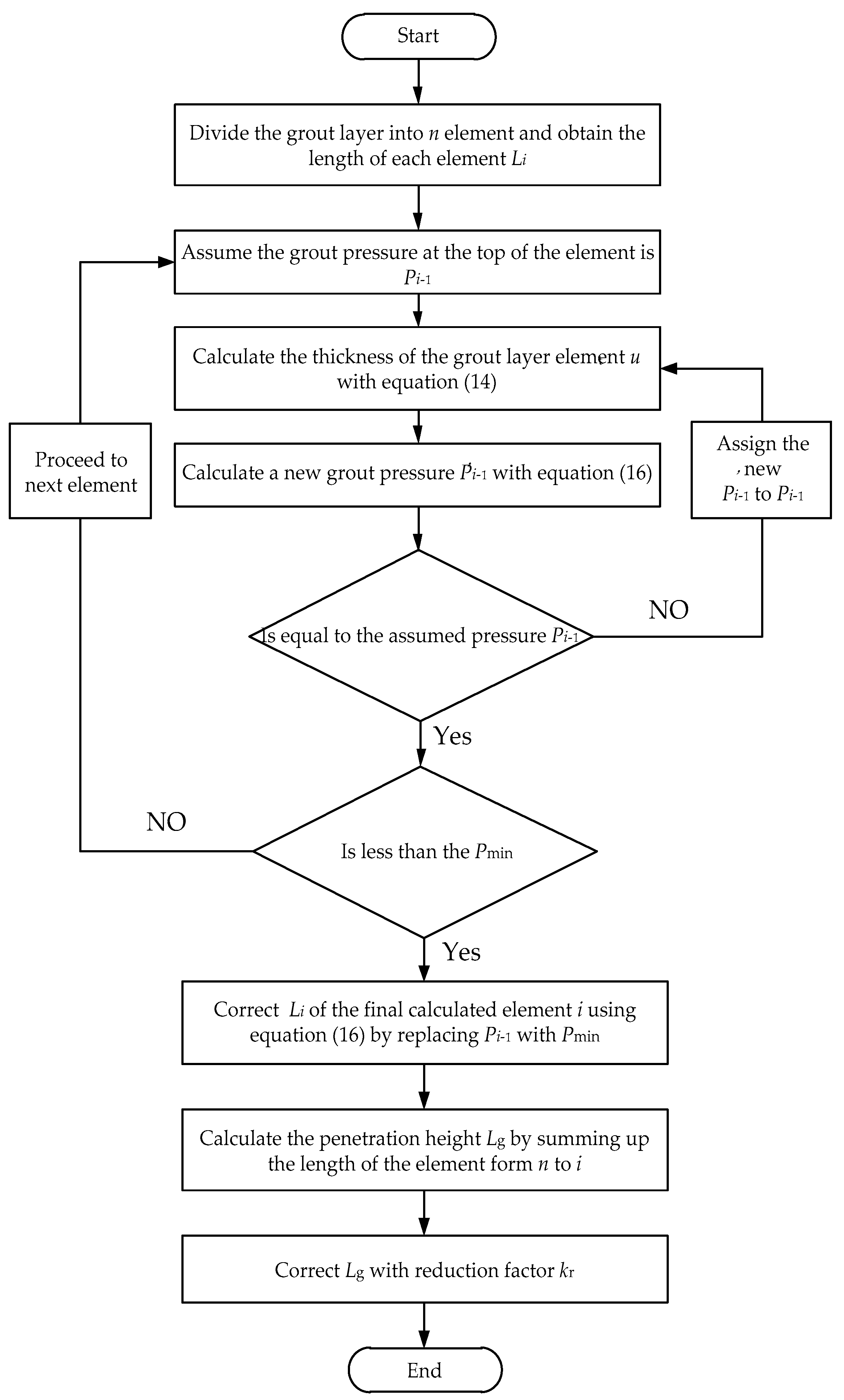
Considering the continuity of the grout pressure and combining the equations of the
n elements, the grouting penetration height in layered soil can be evaluated using the following procedure (the flow chart was shown in
Figure 4).
- (1)
Divide the pile into n elements, and the length of each element is .
- (2)
Assume the grout pressure at the top of the element n is . Calculate the thickness of the grout layer element using Equations (14) and (15).
- (3)
Substitute and into Equation (16) and calculate a new grout pressure . If the new is not equal to the assumed , assign the new to . Then, repeat step (2) and (3) until and are equal.
- (4)
Compare the previously obtained with . If is less than the , assign the to and calculate a new using Equation (16). Otherwise, proceed to calculation of the next element.
- (5)
Repeat steps (2) to (4) until the obtained is less than the . Correct with the mentioned method of step (4). The theoretical grouting penetration height can be calculated by the method of summing up the length of the element from n to i. .
- (6)
Correct with reduction factor and obtain the actual grouting penetration height .
5. Case Study
In order to examine the validity of the proposed procedure, the results of predictions were compared with the measurements obtained from field investigation. The field site was located in Hangzhou, China. The pile, with a diameter of 0.8 m and a length of 40 m, was grouted after its construction. The water-to-cement ratio of the grout is 0.6. The grouting pressure at the pump is about 3 MPa and the grouting pressure at the pile base measured by the pressure gage is about 1.2 MPa. The grout injection rate is about 0.003 m
3/s. The measured reduction factor of borehole profile
is 0.52. The detailed soil properties are listed in
Table 1. The values of the parameters used in this case study are summarized in
Table 2.
The proposed method was adopted to predict the grouting penetration height in this case. Based on the injection parameter and soil properties, the calculated grouting penetration height is 31 m. To evaluate the practical applicability of the proposed method, field investigations were performed to examine the actual penetration height of the grout. The soil is excavated to permit visual inspection of penetration of the grout. The measured penetration height is shown in
Table 3.
Note that exact penetration heights were not obtained for two piles. For pile No. 1, the grout can be seen to squeeze out from sides of the piles to the ground surface. The penetration height should be more than the length of the pile. For pile No. 5, cement layer were not detected within the excavation depth (8 m). It means that the grouting penetration height for pile No. 5 is less than 32 m.
An average height of 35.6 m was obtained by averaging the penetration height of the piles except pile No. 1 and pile No. 5. The predicted values were reasonably close to those measures with an under-prediction of about 10%. Even with the relatively low values, the proposed method provides an important reference to the design of the grouted piles. It can be applied to the engineering to give a conservative assessment of the grouting penetration height for the base grouted piles.
6. Discussion
It should be noted that the grout pressure at the pile base plays a decisive role in the calculation of grout penetration height. The grout pressure at the pile base is usually not equal to the pressure measured at the pump considering the friction losses in the pipes. A reduction factor, which ranges from 0.3 to 0.95, should be used to account for the pipe losses of the pressure [
20]. To give an accurate evaluation of the penetration height, the grout pressure at the pile base should be measured by the pressure gage arranged below the pile base.
The grout migration is a complex process and depends on various factors. It is unavoidable that significant scatter in actual penetration height can be observed. Therefore, it is necessary to adopt conservative assessment for penetration height to ensure the reliable design of grouted piles. The penetration height predicted by this method should be discounted and provide sufficient safety margin.
7. Summary
In this paper, a prediction method of grouting penetration height along the shaft of base grouted pile was proposed. The grout was described as a Bingham fluid. Considering the equilibrium between the driving and resistance forces, the penetration height of the grout can be obtained by the established relationship between flow rate and pressure gradient. From a practical point, an iterative procedure was given to determine the penetration height of the grout in layered soils. In order to examine the validity of the proposed procedure, field investigations were performed to examine the actual penetration height of the grout. The measurements proved the reliability of the proposed method. Considering the uncertainty of grouting pressure losses and roughness of the pile borehole, it is necessary to adopt conservative assessment for penetration height to ensure the reliable design of grouted piles.


