1. Introduction
The study of the impact of human activities on the environment and climate has become increasingly crucial over the past few years. Our research seeks to address the practical need of monitoring very shallow waters for improved acquisition of environmental parameters. The main purpose is to solve the difficult problem of carrying out monitoring and sampling in wetland areas. Wetlands cover between
and
of the Earth’s surface and include mangroves, peat bogs and swamps, rivers and lakes, river mouths and deltas, floodplains and flooded forests, rice paddies, shallow coasts, and even coral reefs [
1]. They are present in practically every country and climatic zone, from the polar regions to the tropics, and are essential both for biodiversity and for human life. Thanks to their abundant animal and plant life, wetlands act as natural purification systems. They represent a major source of water, biodiversity, and carbon, and because of this, they are resilient to climate change. The organisms that populate wetlands and the chemical processes that occur in these areas serve as indicators for changing environmental conditions [
2] since they reflect the impact of anthropogenic climate change. This means that monitoring these areas is of fundamental importance. However, surveying wetlands is arduous, as the technological solutions currently available for use in in this peculiar environment have proven inadequate. In particular, water sampling and monitoring in the very shallow waters that sometimes characterize swamps, rivers, lakes, and coastal areas is extremely complicated. In recent years, Autonomous Surface Vehicles (ASV) have been deployed to increase shallow water accessibility and hence raise the quality of the surveys performed in these areas, as shown in [
3,
4,
5]. Numerous ASVs with more or less enhanced capabilities have been developed over recent years by academic and research institutions, as illustrated in [
6,
7,
8]. While some of these vehicles have been specifically designed to work in shallow waters, nevertheless, as shown in
Section 2, they usually adopt propulsion units that are unsuitable for operation in extremely shallow waters, namely those between 5 and 15 cm in depth.
The challenges involved in wetlands’ monitoring have brought together two research bodies who have joined their complementary experiences with the aim of developing a technological solution based on unmanned vehicles: the INstitute of Marine Engineering of the Italian National Research Council (CNR-INM) and the Electrical, Electronics, and Telecommunication Engineering and Naval Architecture Department at Genoa University (DITEN). These two bodies are now coming together to build ASV systems suitable for monitoring extremely shallow waters and characterized by modularity, new construction techniques, and innovative propulsion units based on the pump-jet, the specific topic on which this article is focused. The pump-jet is a steerable pump-based thruster suitable for shallow water and non-standard applications, which can be used both as a maneuvering aid and as the main thruster. It provides 360 degrees of continuous steering, a compact design, installation flush with the hull, and virtually no risk of damage from grounding or floating debris.
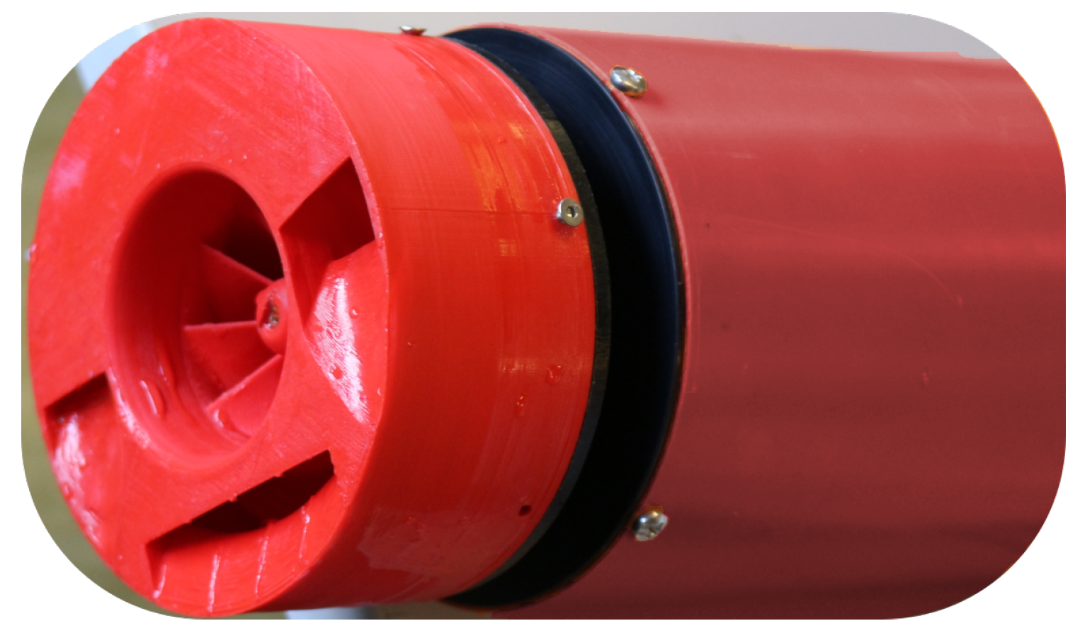
At present, no small-sized (under 1 kW) pump-jet-based solution is available on the market, and the available literature on this kind of thruster is scarce. For this reason, in order to develop a propulsion unit based on the pump-jet concept for shallow water ASVs, we had to design our system from scratch, from modeling to design and construction. This paper describes a Pump-Jet Module (PJM) (shown in
Figure 1) constructed with innovative techniques, together with the mathematical modeling used for designing the system. Design characteristics, production techniques, bollard pull tests and experimental results are reported in this article. This research is intended to pave the way for the application of pump-jet technology to lightweight ASVs for extremely shallow water applications.
2. PJM Application
Given the growing interest in the construction of ad-hoc solutions to improve efficiency and effectiveness in wetlands’ monitoring, the authors have defined a class of ASVs whose characteristics respond to the specifications of various missions. ASV design is based on the hints described in [
9], which take inspiration from operational requests from Italian public and private organizations that monitor wetlands and shallow waters. The main indications that drove the design of the PJM are that: (a) any propulsion system to be used in extremely shallow waters has to be able to work on a small vehicle with minimal draft; (b) the system has to be capable of surviving in the probable event of grounding; (c) it has to allow the vehicle on which it is mounted a high degree of controllability; and (d) must be both light and small.
ASV propulsion systems often adopt commercial propulsion units. The most common systems used in ASVs for monitoring shallow waters are free- or ducted propeller propulsion modules, water jet systems, and aerial systems. A schematic review of these systems is shown in
Figure 2.
Free propeller modules with a vertical fin supporting the propeller are amongst the most common (e.g., [
10,
11,
12]) and most efficient systems currently available and allow considerable design flexibility. On the other hand, these propellers are extremely liable to damage from collision with obstacles at low depth and are therefore not recommended. Ducted propulsion modules have the same structure, but the propeller is protected by the presence of the duct (e.g., [
13,
14]), in some cases with an azimuth system (also with rim-driven technology [
15]), combining high control capabilities with high thrust at low speed. Ducted systems have similar problems as the above-mentioned free-propellers, in that the unit may be subject to impact with the seabed. Free propeller thrusters whose disc is completely contained within the hull (e.g., [
16]) offer partial protection from impact and the possibility of accessing shallower waters, but do not represent a real improvement either in terms of maneuvering or protection. Aerial propulsion (e.g., aerRobotix [
17]), which may at a first appear to be an excellent alternative for shallow water operations, has the disadvantage of the propeller’s large size (compared to the vehicle) and low efficiency, which also involves poor design flexibility and high noise levels, making it unsuitable for protected areas. The use of water jet propulsion could provide a good alternative, especially because the lack of protruding appendages solves the problems of draft and navigation in shallow water (e.g., Sonobot [
18,
19]). However, if the system is flush with the hull, this will result in low maneuvering capacity, thus barring hovering functions. If the solution involves a complex and damage-prone directional system (e.g., [
20,
21]) for the nozzle with a reversing bucket to reverse thrust, it will not satisfy the impact-resistance requirement of shallow waters research.
Some interesting amphibious-like solutions such as [
22] are currently being employed in the laboratory, and these may prove to be of great interest in the future. Other interesting solutions being used to work underwater in the proximity of the seabed have been proposed in the U-CAT [
23,
24] and WIEVLE [
25] robots; these avoid the risk of damaging the propulsion unit and are suitable for AUVs and ROVs. This range of approaches suggests that various solutions may be adopted to extend the survey ability of ASVs.
In order to combine the ability of working in only a few centimeters of water, combined with satisfactory control abilities, we propose an ASV design based on an azimuth thruster. This solution, known as the pump-jet, has previously been adopted in ships working in shallow waters, but has never been adopted in robotic vehicles.
Vehicles expressly designed to work in shallow and confined waters and in harsh environments may minimize the effects of possible impact with the waterway ground by combining a flat bottom with the use of a module. The PJM is suitable for these vehicles and for accessing extremely shallow waters since it satisfies the requirements of reduced immersion, controllability, propulsion intactness, and minimal impact on the environment. The PJM can work in minimum water depths as low as 50 mm without risking damage; the possible impact of the vehicle with outcropping stones, roots, or similar objects that can damage the propulsion system with consequent risk of losing the vehicle is minimized by the pump-jet geometry. Since ASVs must be able to access narrow areas for sampling, even in the presence of external disturbances, they should be fully controllable both in station keeping and in path following. For this reason, a propulsion layout based on four azimuth thrusters (like the PJM) is considered a suitable approach.
The Pump-Jet
The pump-jet operates on the principle of a vertical axis pump. An impeller sucks in water from beneath the hull, and through the blades, the water is whirled tangentially and radially outward into the casing chamber. The fluid gains both velocity and pressure while passing through the impeller. The outlet nozzles in the steerable casing accelerate the flow, and a jet of water produces thrust horizontally beneath the flat-bottomed hull.
The first prototypes of steerable thrusters with outlets placed in the bottom of watercraft were invented around 1920 [
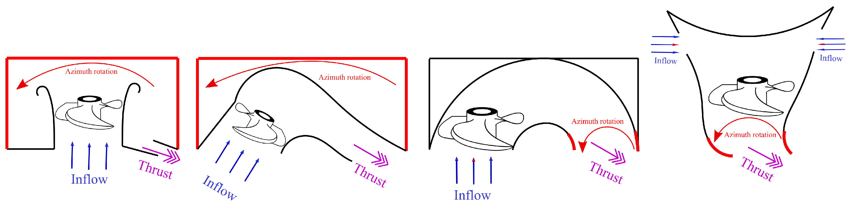
26], but more recent systems were developed around 1975 for military craft. Today, these constitute an alternative either as a main or as an auxiliary propulsion unit. Various manufacturers produce them: Veth [
27], Schottel [
28], Jastram [
29], and Tees White Gill [
30]; a schematic reproduction of these products is displayed in
Figure 3.
Each of these manufacturers has developed its own pump-jet system with unique characteristics. The main advantage of using pump-jet s is maximum thrust at minimum draft. Another advantage claimed by the manufacturers is that effective thrust can be achieved even at higher speeds. Since the pump-jet is installed flush with the hull, it does not produce a significant increase in resistance if compared to other systems, and there is no risk of collision with floating debris. This system is suitable for operating in extremely shallow waters, since the risk of damaging the system in case of grounding is very limited. While this system was initially developed as a maneuvering device, currently, it is also used as a main thruster. In addition to all these advantages, most of the manufacturers claim that the system is distinctly low-noise.
Veth produces various versions of the pump-jet, but the most space-saving one is the Compact Jet, where the propeller is placed at an angle of 17°, so that greater thrust can be generated when water flows through a hydrodynamic streamlined housing control grid. The entire system, grid plus propeller, is 360° steerable. The whole system is placed on the vertical plane of the vessel, whereby water is sucked in obliquely from under the ship: this makes this solution similar to water jet propulsion. Veth claims that the system is low-noise. The complexity of the system lies in steering an oblique propeller.
The Schottel pump-jet (SPJ) differs in part from the Veth-type control grid; because the Schottel pump-jet is based on the principle of centrifugal pumps where centrifugal forces ensure that the fluid is pumped through a 360° rotating outlet nozzle. In this system, the pump shaft is coaxial with the azimuth shaft, thus reducing bulkiness. The SPJ owes its success to compact design.
The Jastram azimuth grid thruster is a special system requiring two openings in the hull. The first, fixed, is used by a propeller that generates a high volume of water at low pressure, which flows towards a second, steerable, opening through a horizontal channel. The actual thrust direction is given by the rotation of this second opening.
The Tees Vertical Shaft Unit system is a unique piece featuring two water inlets on the sides of the hull pushing water downwards where a steerable grid pushes the water in the desired direction. The gain in space and the hydraulic advantages are obvious. On the other hand, this system constrains hull shape design and seems to be more suitable as a maneuvering system than as a main thruster.
Summing up, the pump-jet concept is a consolidated design based on the simple application of basic physical laws with acceptable efficiencies. Very few studies exist in the literature on pump-jet design and functioning, and they are related to the effects of the pump-jet on riverbanks [
31] or on the performances of hulls that mount this kind of system [
32]
3. PJM Design
The geometry of our PJM was inspired by the existing systems mentioned above [
33]. Our aim in installing a PJM on an ASV was to prevent damage if the vehicle collided with the bottom and to reduce possible additional resistance.
The main idea behind the PJM was to design a watertight module that can easily be dismounted from the ASV for easy transportation and can be employed on different vehicles. For compactness, the control unit is embedded and contained inside the module. The azimuth motor provides continuous feedback on position, guaranteeing high maneuverability with high rotating nozzle speed.
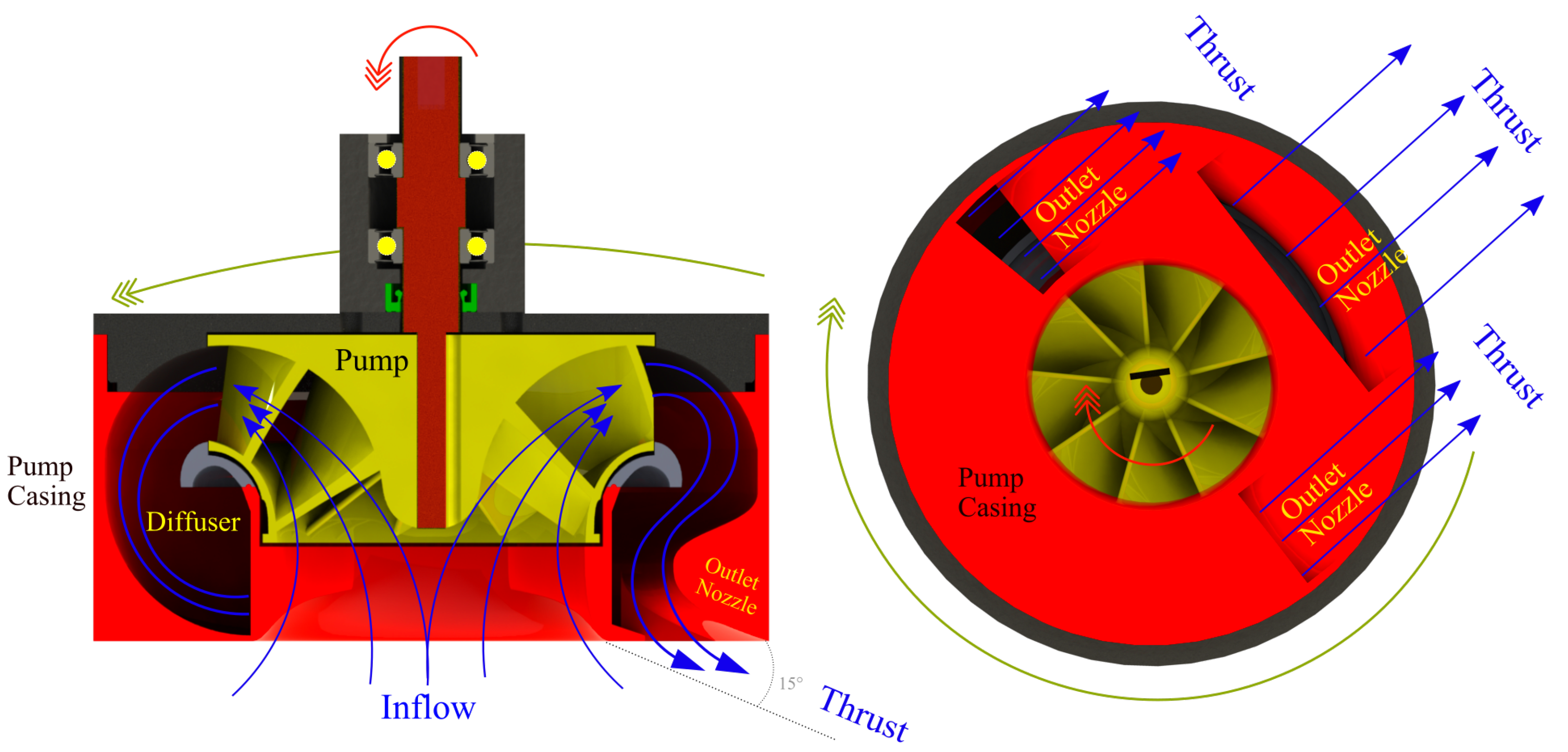
As mentioned before and shown in
Figure 4, the pump-jet principle stems from a mixed-flow or centrifugal pump, which produces static pressure that causes water flow to stream out of a steerable nozzle. The (usually vertical) pump sucks in water from under the vessel; the water is channeled through a casing and flows out through a nozzle positioned at the bottom of the unit near the inlet duct. Thrust is produced by conversion of static pressure into kinetic energy and potential energy. When water flows out of the pump, energy is transformed into kinetic energy, which leaves the system at high speed through the nozzle opening. Since thrust is the product of water flow by water velocity, the greatest advantage of the pump-jet is that it only requires a very low volume flow to generate a propulsion force. The entire casing is designed to be 360° steerable; the water jet trajectory is relatively short, minimizing frictional losses, and its path through the casing chamber is also relatively short and three-dimensional: this and other factors make the system efficiently compact.
The nozzle area at the bottom of the propulsion unit is approximately one third of the intake area, so water intake velocity is only one fourth of outlet velocity in the nozzles. This is important to minimize the risk of sucking in unwanted bodies in shallow waters.
The outlet angle of the water is approximately 15° from horizontal: almost the entire jet thrust is converted effectively into forward thrust. At the same time, in shallow water, the impact on the river/lake bed or sea bed is reduced, and measurements can be carried out with limited disturbance, as the water is expelled almost horizontally from the PJM and rises towards the surface as soon as it leaves the nozzles.
The high velocity of the water leaving the nozzles means that the PJM can be used to maneuver vessels at high speed since considerable thrust can be achieved even at high speeds. This is due to the high intake performance of the mixed-flow pump.
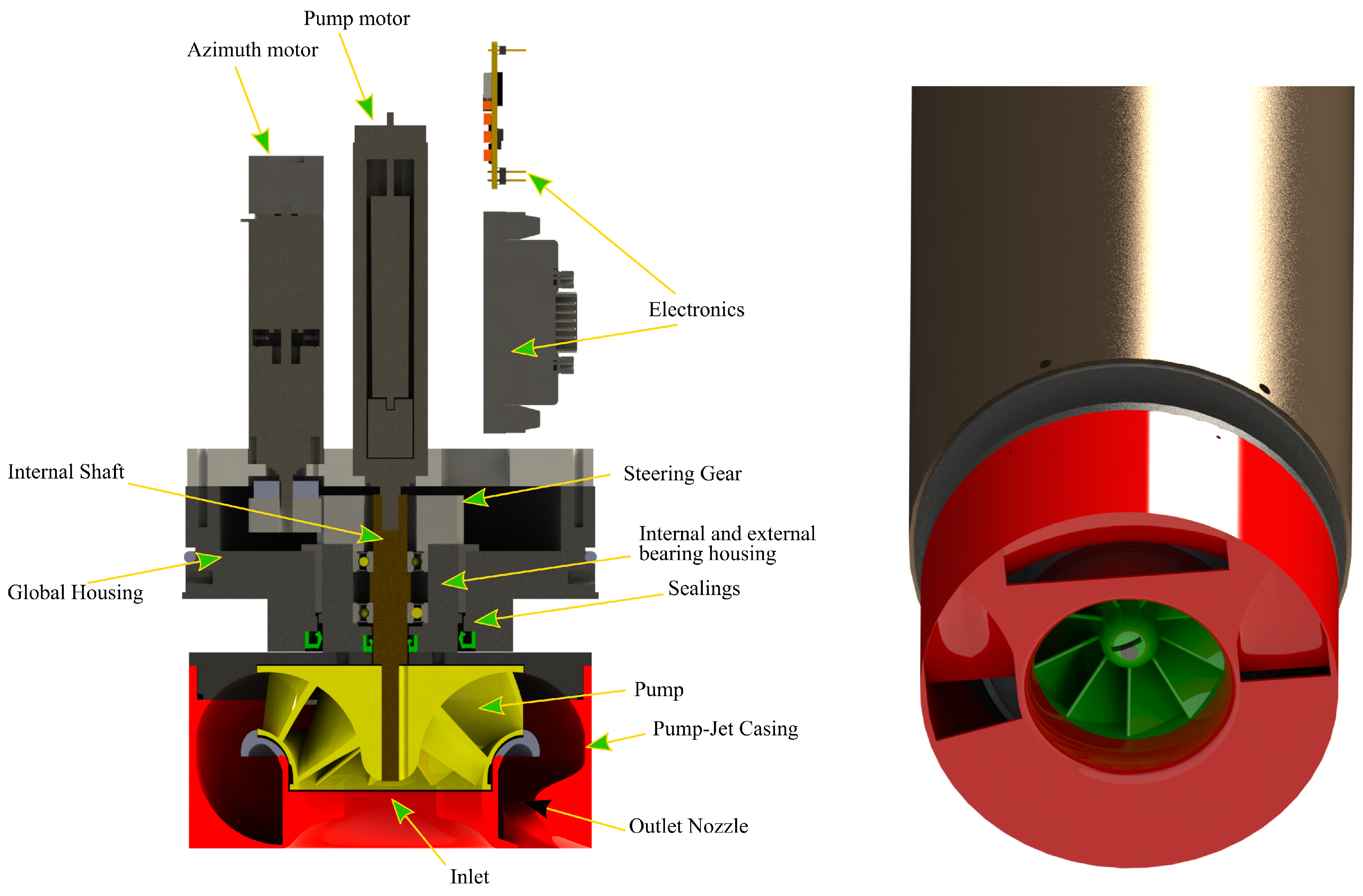
As far as construction is concerned, the pump impeller was 3D printed for ease of production, and also because this production method made it possible to test different pumps. For the same reason, the module itself was constituted by a 3D-printed element hosting both the inlet duct and the outlet nozzle (the element governing thrust production), as shown in
Figure 5. This element is structurally connected to a hollow shaft made in Polyoxymethylene (POM) that houses the bearing for the pump-shaft and is supported by a self-lubricating bushing, in turn hosted by a housing made in POM; this represents the structural element of the thruster. Two Nitrile Butadiene Rubber (NBR) sealing rings, one for the hollow shaft and the other for the pump-shaft, guarantee water-tightness. The housing constitutes the main support for the two brushless electric motors: one drives the pump, and the other governs nozzle steering. The first motor is coaxial with the pump, while the second shaft axis is parallel to the shaft of the pump, and motion is transmitted to the nozzle by mean of two fiber-reinforced plastic gears, where the driven gear is screwed to the hollow shaft, which in turn is screwed to the nozzle. On top of the module’s housing, a plastic pipe with a plastic cap is installed, and two NBR O-rings seal the entire module. Inside the volume formed by the plastic pipe, the brushless motor, the control electronics, and the communication system are contained. In this way, the electric power cable is the only additional element entering the module, thus creating a one-piece element.
All the elements were made of lightweight inert plastics, so as not to compromise the samples acquired by the ASV mounting the PJM. A 3D printer was used for building the PJM components, thus allowing us to prototype the system quite rapidly. Moreover, this made it possible, during the testing phase, to modify promptly and test various configurations, and no high-cost mold was necessary for the impeller and the outlet duct.
3.1. Pump Design
To start designing the system, the PJM’s geometry had to be defined. Based on the ASV’s size and thrust needs, the authors used the theory governing mixed-flow pumps to define the geometrical constraints underpinning the entire design.
3.1.1. Geometric Data
The maximum diameter of the PJM was defined based on the following parameters: draught of a small-/medium-sized ASV, payload, and main dimensions. The desired value was identified as mm.
A number of geometric characteristics constraining the PJM design were identified; most of these constraints were related to the main diameter
(see
Figure 6), which must make it possible to scale the system for different diameters and choose the one that better matches mixed-flow pump requirements and the geometrical constraints of the vessel.
To constrain the design, the height of the casing was imposed to be to allow for the future PJM scaling. The inlet diameter of the Impeller was imposed to be: , and the maximum outlet diameter of the impeller: , while the height of the impeller outlet was defined as ; therefore, the impeller areas were: and . These values determined the overall dimensions of the PJM, and was particularly important because, as shown below, this value influences the pump head and the RPM of the impeller, thus constituting a key element in selecting the motor.
The chosen water discharge angle with respect to the PJM bottom was deg.
As a final geometric constraint, to achieve the requested outlet area (as shown in
Figure 7), the discharge nozzle was subdivided into three channels, then the outlet area was calculated by summing up the three areas:
With the latter value all the geometric data were determined.
3.1.2. Propulsion Data
The design thrust of the PJM was identified as N. The value was obtained from preliminary calculations on the requirements of small-/medium-sized ASVs. The module may be considered as a free-running propeller studied for bollard pull and low speed. The exact amount of thrust was validated during moving tests (e.g., in self-propulsion in a towing tank) with the module installed on various ASVs, whose advance speed may influence (or not) the exact amount of thrust produced by the module (resulting in a thrust deduction factor and/or a wake fraction).
Thrust roughly originates from water flow multiplied by outlet water velocity. For this reason, all these parameters must be calculated in order to model the thrust unit. The vessel’s propulsion thrust derived from the change in momentum taking place when water enters and leaves the jet thruster system [
34]. Therefore, the thrust produced by the pump-jet system is expressed as follows:
where
is the discharge area,
is the outlet flow speed, and
the inlet flow speed. With respect to the output angle, the thrust is:
Since the value to be extracted is outlet water velocity
, then water flow must also be calculated. To do so, we can use the equation:
where
is, in first approximation, negligible. This assumption is supposed to work since this value does not substantially influence the value of
. During impeller design, a little inflow velocity was assumed possible due to vehicle speed [
35]. As mentioned above, case-by-case tests were performed to evaluate PJM thrust at various ASV velocities. The flow rate at the outlet therefore is:
3.1.3. Pump Head
The data calculated above led us to defining the pump head necessary to design the impeller. From the Bernoulli equation:
where
is the head associated with the pump and
and
the outlet and inlet static pressures, which are equal because the atmospheric pressure added to the water column is constant.
is the static difference in the head between inlet and outlet, which in this case was null, and
is the term associated with the loss of head due to the flow through the system and the pump.
These losses were present in the system; thus, it was necessary to add these values to the pump head calculation. Losses can be calculated as the sum of two factors:
where
are the losses due to pump efficiency. Assuming a small-sized mixed-flow pump, the efficiency was considered to be:
, internal losses, is defined as the sum of the losses at the intake and the nozzle (also due to 3D machining imperfections):
The
value was added as a
coefficient to the value of the pump head.
This allowed us to calculate the total head of the pump:
In addition, the power associated:
Using this value, we could identify the pump type by calculating the pump specific speed:
as shown in
Figure 8.
Since the motors that the authors pre-identified for the PJM design had a maximum operating speed of 1200 RPM, then our , then the pump was a mixed flow pump of the type reversible Francis turbine. The consequent ratio was chosen to be 1.5, which gave us the inlet/outlet ratio .
3.1.4. Impeller Design
Mixed flow pumps borrow characteristics from both radial flow and axial flow pumps. As liquid flows through the impeller of a mixed flow pump, the impeller blades push the liquid out away from the pump shaft and to the pump suction at an angle greater than
deg. In Francis pump impellers, design factors, requiring Euler’s triangles to be known, are important and are obtained from experimental designs and data. Various ratios are used and can be found in the literature [
36].
To design the impeller vane layout, the following parameters are required:
Meridian velocities at inlet and outlet
Impeller outside diameters
Impeller vane inlet and outlet angles
Velocity triangles to be drawn for several streamlines (minimum of three streamlines)
Following the design procedure suggested by [
37,
38], the authors found a time-saving procedure for designing the Francis pump for rapid prototyping. This involved:
Selection of the inlet and outlet diameter of the pump impeller and the various geometric data
Meridian flow analysis resulting in the surface of revolution
Calculation of blade angles from hub to tip based on free vortex theory
Geometrical transformation of each surface of revolution into a plane with flow angles
Reverse transformation of cascade geometry and flow data to the back-to-back intersections on the surfaces of revolution
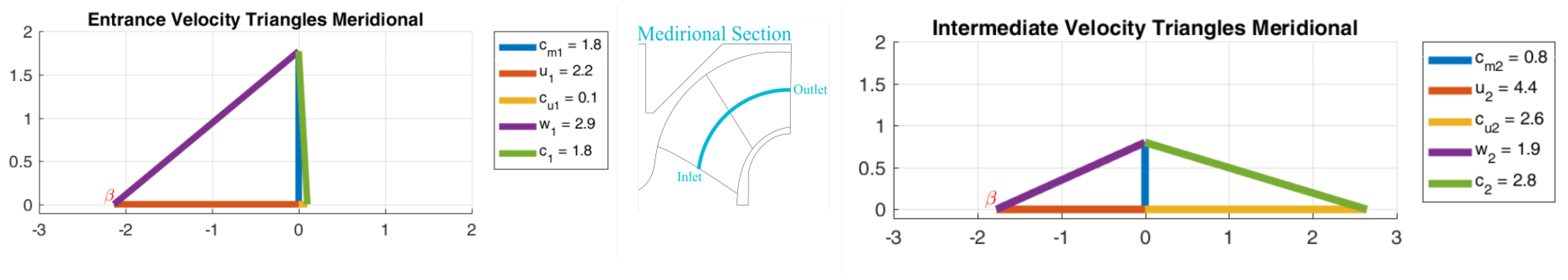
The velocity triangles of the inlet and outlet of the impeller are shown in
Figure 9 with their reference names.
The main design elements are listed below:
The vane discharge angle was the most important design element since all theoretical characteristics were determined by the vane angle alone. All design constants depended on . This value was fundamental for determining pump design since normal head and capacity increase when increases. This angle should be between 15° and 35° in order not to affect efficiency appreciably.
is a speed constant used for calculating impeller diameters when RPM and pump head are defined as in our case. Smaller pumps require a higher value of to compensate losses.
is the mean effective diameter, which, for mixed flow pumps, divides the flow throughout the impeller into two equal parts.
The capacity constant value is important since it is obtained from experimental data. Differences from these data may lead to leakages and losses.
Entrance velocity is supposed to be the velocity just ahead of the vanes. This depends on . Usually, depending on the impeller approach, is equal to the velocity through the impeller eye or slightly lower.
The minimum number of vanes required is six for low and large pumps. Smaller impellers and impellers with smaller head require fewer vanes, but for our experiment, we chose three different numbers of vanes: 8, 9, and 10, to lower the slip factor. The number of vanes depends on . The lower , the lower the number of vanes.
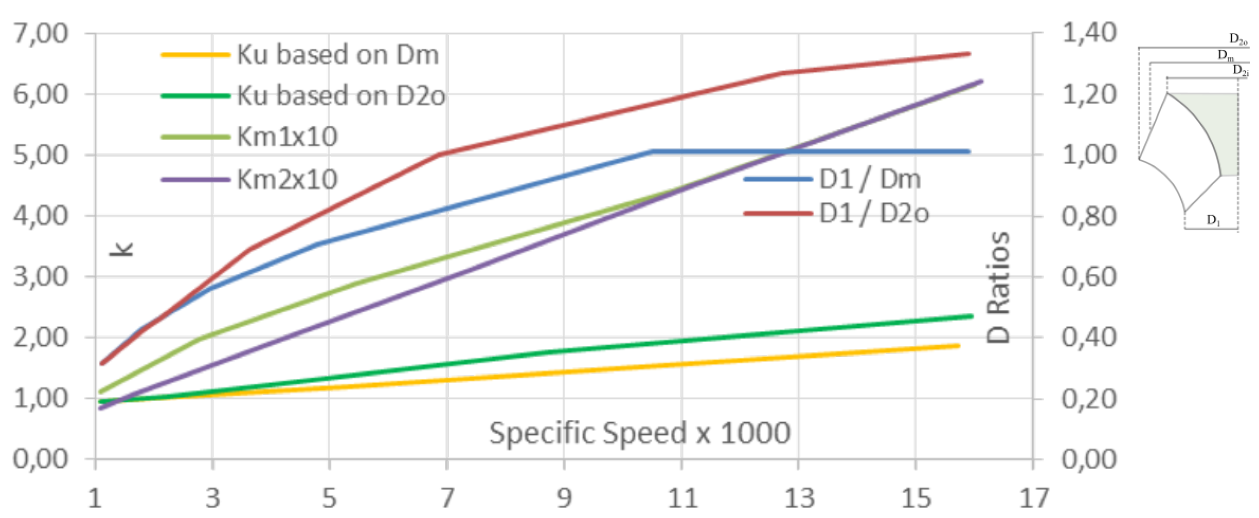
3.1.5. Pump Geometric Parameters
The various geometric design parameters for developing the mixed-flow pump were obtained from [
36] and its experiment-based coefficients. The graph in
Figure 10 was used to obtain the diameter ratio
value of 0.65. This value allowed us to calculate all the inlet geometry data as follows: tip diameter (and radius) of impeller
, mean diameter (and radius) of the blade
, and the inlet root diameter (and radius)
, which divides the flow into equal parts.
Figure 10 was also used to obtain the outlet geometry data as follows:
Tip diameter (and radius) at the outlet from , mean diameter (and radius) at the outlet , and the root diameter (and radius) at the outlet .
Blade heights can also be calculated: the blade height inlet was derived from initial geometrical analysis and was , while blade height at the outlet can be calculated as .
With all these data, based on geometric considerations, it is possible to calculate and design the internal layout of the PJM.
3.1.6. Velocity Triangles
The impeller of the PJM system was designed using velocity triangles.
The area of the inlet was obtained from:
Thus, the axial velocity is:
and
If the liquid enters the impeller without a tangential component, the whirl component
is low (zero or 0.1), in our case, we imposed:
Then, we can calculate the component:
In addition, the resulting velocity:
This can also be done for the outlet where the area is obtained:
Thus, meridian velocity at the outlet:
The tangential component of absolute velocity at the outlet can be calculated from:
Then, we can calculate the component:
and:
Fluid slip due to the difference in pressure and velocity between the trailing and leading faces of impeller blades is important in radial impellers. A deviation in the angle at which the fluid leaves the impeller from the impeller’s vane has to be taken into consideration. This value is evaluated through the Stodola equation. The Stodola [
39] slip value comes close to the exact correction number if the number of vanes exceeds six and
is small, then the correction factor is:
and:
By applying this correction, the vane entrance angle is calculated:
The vane outlet angle is calculated:
Based on the above-mentioned dimensions, the values obtained are those summarized in
Table 1:
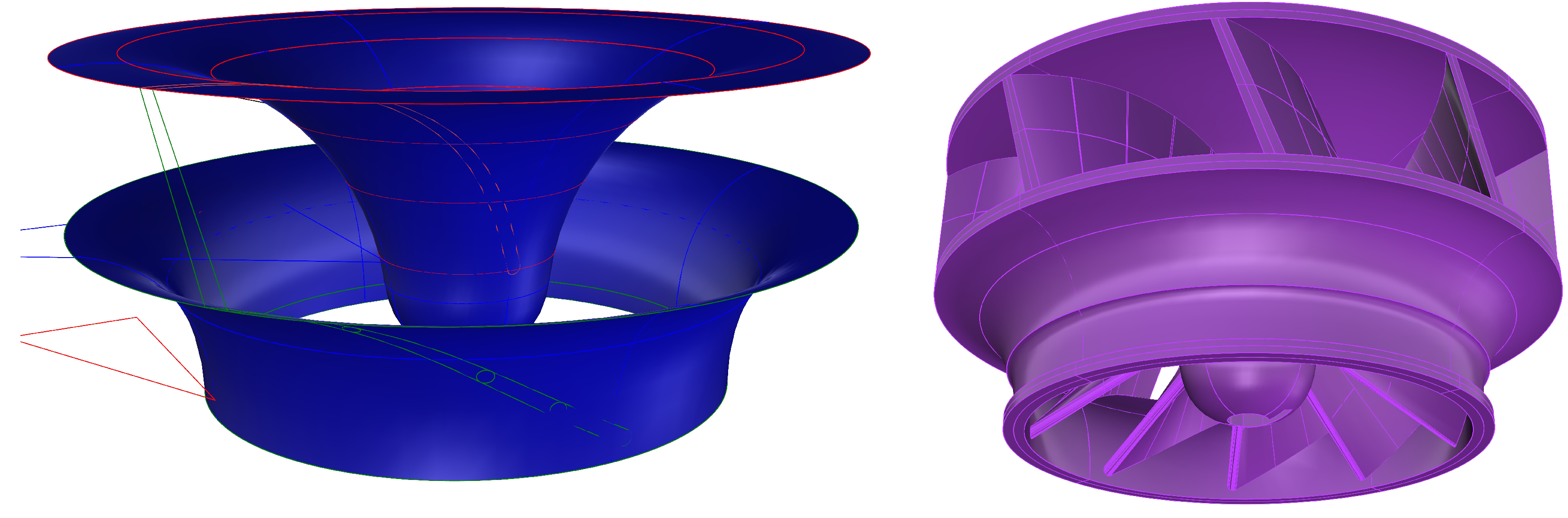
3.1.7. Pump 3D Drawing
Based on these data, obtained for various sections, the vanes were drawn by means of a 3D computer graphics software.
As shown in
Figure 11, the impeller was drawn using the velocity triangles and by applying results to the various sections of the vanes when the obtained chord was divided into equal intervals. The resulting velocities and blade inlet and outlet angles were obtained from the velocity triangles. An example of the angles used to draw the 3D model of the pump is shown in
Figure 12.
3.1.8. Casing Design and Drawing
To design the casing, the fundamental parameter was the outlet area
, which was determined during the first design stages as the equilibrium value between the possible pump head with a 120-mm diameter and the expected motor RPM. Since the outlet of this system was subjected to a sudden change in the water flow section, a consequent and localized head loss was present and can be calculated with the formula:
where
is the average outlet speed and
a dimensionless parameter (so-called coefficient of localized resistance), which depends, essentially, on the geometric configuration and is between 0.9 and one for sharp edge outlets such as those that can be encountered in the outlet of a PJM. This value was used to initially dimension the pump head. To design the casing, we followed the criterion of removing any possible sharp edge and took into consideration that the rotatory component the pump impeller induces on the flow creates a jet that is a bit asymmetrical.
Therefore, to obtain the desired area
, we provided three openings: one was central in the frontal part of the PJM, and two were on the sides. The two side openings were non-symmetrical, as shown in
Figure 7, and the geometry of the outlet nozzles was obtained after several tests made by varying the geometry of the outlets. The dissemination of these tests is reported in
Section 5.
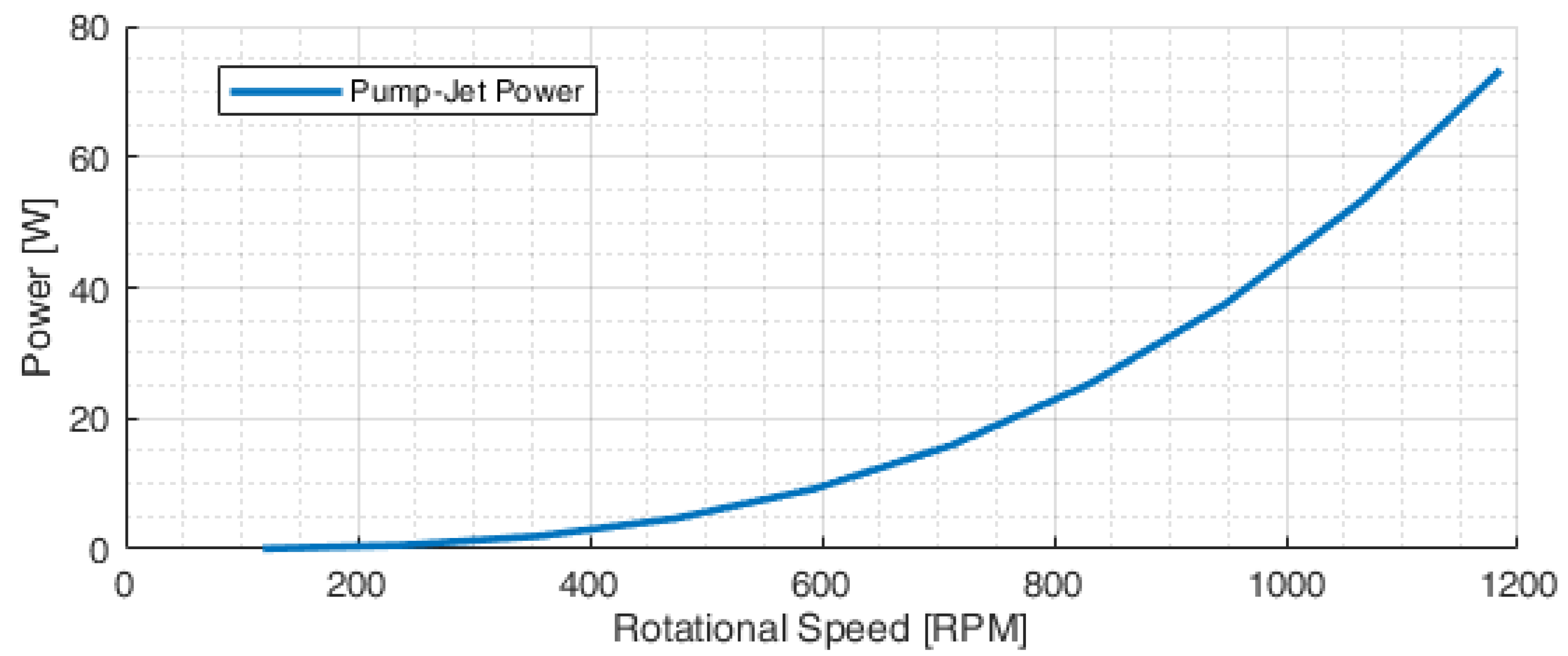
3.2. Motors’ Layout and Choice
The expected power consumption for the PJM was obtained from Equation (
12) and is shown in
Figure 13. By considering 0.95 mechanical efficiency (for the bearing efficiency and the sealing frictional resistance) and a motor efficiency of 0.85, the expected maximum power at the design point was around 90 W.
Considering this value, the chosen motor for the PJM impeller was the Maxon Ec-4pole with a 14:1 reduction gear. It is a highly efficient and reliable 36-V brushless motor with a 120-W power supply. It has an excellent working point around 1185 RPM at 90 W. The chosen azimuth motor was the Faulhaber 2232-BX with a 59:1 reduction, which guaranteed 0.85 Nm and a rotational speed of 492 deg/s. This means that the azimuth system can be steered 360 degrees in less than one second. This motor has an integrated absolute encoder that allows constant information on the exact thruster position. This element, together with the 59:1 reduction coupled with the gear reduction of 2:1, provides the exact position of the thruster with precision well below 0.1 deg and permits continuous rotation in any direction.
Table 2 lists the characteristics of the chosen brushless motors.
3.3. Hardware Control System and Power Supply
As illustrated above, the motors with the corresponding encoder with the controllers ESCON Module 50/5 were all installed in the pump-jet module. The controller was a small-sized, powerful four-quadrant PWM servo controller for highly efficient control of brushless EC motors up to 250 W.
For the azimuth brushless DC-motors with absolute encoders, the Faulhaber MCBL3006S-AES was chosen. This system has overload protection for electronics and the motor and self-protection from overheating and over-voltage. The controller together with the motor’s absolute encoder allowed for a positioning resolution of 4096 steps per revolution; this means, if we consider the reduction gear, 483,328 steps for a deg rotation.
The actuation module was based on a Huzzah ESP8266 board, which is an Arduino-like microcontroller board with Wi-Fi capabilities. The Huzzah also offers considerable I/O expandability with 9 GPIO (General Purpose Input Output) I/O digital channels, 1 analog input channel, and 2 UARTs (Universal Asynchronous Receiver-Transmitter) serial I/O channels. Additional digital, analog, serial, etc., I/O channels can easily be added to the board thanks to the presence of one I2C and one SPI bus interface. The actuation module communicates with the vessel’s control system through a Wi-Fi link, with the servo controller of the propulsive motor through an RS-232 serial channel, and with the servo controller of the azimuth motor through an additional SPI D/A channel. Power on/off, enable/disable, and fault signals are managed by means of the GPIO channels. One of the main objectives of this propulsion unit was to provide a completely closed module that communicates with each control unit without requiring a cable. With this in mind, the power supply of the module came from an external source (e.g., the battery of the ASV). Alternatively, in a modular approach, the power supply could be installed inside the module, thus creating a completely closed module that only communicates with the external world through a Wi-Fi connection, but does not require an external power supply or communication cables. For this purpose, the canister of the module was bulky enough to be able to house a battery module.
The adoption of azimuth propulsion and the
deg rotation capability required robust guidance techniques to provide precise and reliable motion control and smooth, jerk-free motion, combined with satisfactory driving performance. The problem of avoiding singular configurations of azimuth thrusters was addressed in [
40]: these configurations may cause poor maneuverability and temporary loss of control, a circumstance that is recovered very slowly if the steering system is slow. This is avoided using the PJM high steering speed, and the adoption of the MCBL3006S-AES control system was suitable for controlling the PJM. To guarantee that ASVs adopting a PJM are able to satisfy specific operational requirements (path following, station keeping, vehicle following), suitable guidance and control schemes were developed and implemented. This was done in combination with the development of suitable thrust control mapping also related to data quality since collected data could be affected by abrupt maneuvers, rough azimuth changes, or jerky motion.
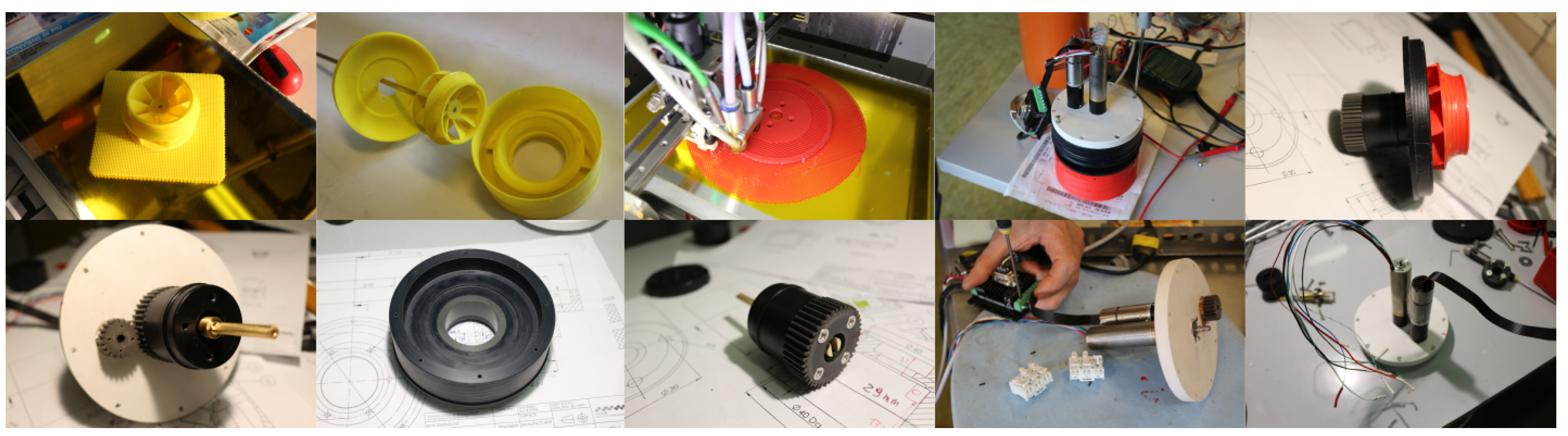
4. PJM Construction and 3D Printing
The physical construction of the PJM was entirely carried out at the CNR-INM laboratories. Pictures of the manufacturing process are shown in
Figure 14. As described in
Section 3, the PJM was made out of plastics like HPDE, POM, and PVC. Non-rotational elements were constructed using a CNC mill-machining machine, while all the rotational parts (except from commercial parts like self-lubricating gears, self-lubricating bearing, and metallic bearing) were made in plastic by means of a lathe machine. 3D printing allowed us to carry out the above-mentioned tests on the various openings of the PJM, and while in this article, the authors only report on the final design of the PJM, various pumps and nozzles were designed and tested.
The pump impellers were built using a desktop filament 3D printer in PLA (Polylactic Acid) and ABS (Acrylonitrile Butadiene Styrene) for the testing phase, and the final version was built in PETG (Polyethylene Terephthalate), a non-hygroscopic, robust material. Various casings were designed and printed in ABS since this material is non-hygroscopic and robust.
Thickness was slightly adjusted between the first version and the final versions to take into consideration the behavior of the 3D printer’s layered structure.
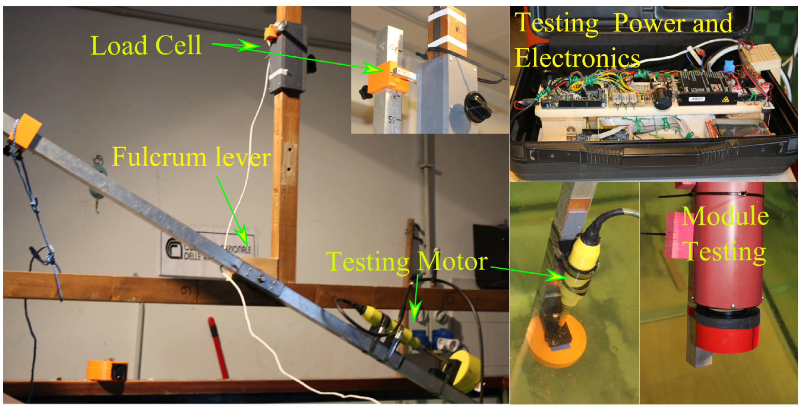
5. Experimental Tests and Calibration
Direct validation of bollard thrust tests was performed in a small pool at the CNR-INM laboratory in Genova to measure thrust and torque delivered by the impeller. Tests were performed at different stages during the design process using an ad hoc low-cost system for the measurement of thrust exerted by naval thrusters. The system, shown in
Figure 15, was constituted by an aluminum fulcrum lever in which the thruster was positioned on one side and a load cell with a strain gauge and its amplifier positioned on the other. The load cell was connected to an Arduino Due micro-controller, which was used to record the acquired data and manage the Maxon Servoamplifier 4-Q-EC - DECV 50/5 that was used to command the motor. Data were recorded on an SD card, and the output string was defined as follows: date; thrust (g); motor speed, current, voltage; Hz and RPM from the motor’s hall sensors; driving reference Voltage (V).
The driving reference voltage was used to command the system. This voltage was also used when the module was mounted on the ASV, and the command was given via Wi-Fi. Bollard thrust tests were performed with the propulsion unit in forward direction and with various steering angles.
Table 3 summarizes the tests performed on the PJM system. The authors report on tests where the entire PJM diameter was varied and tests where the diameter of the impeller, the number of blades, and the outlet geometry were varied. Tests were also performed at different depths, but no significant variation was recorded.
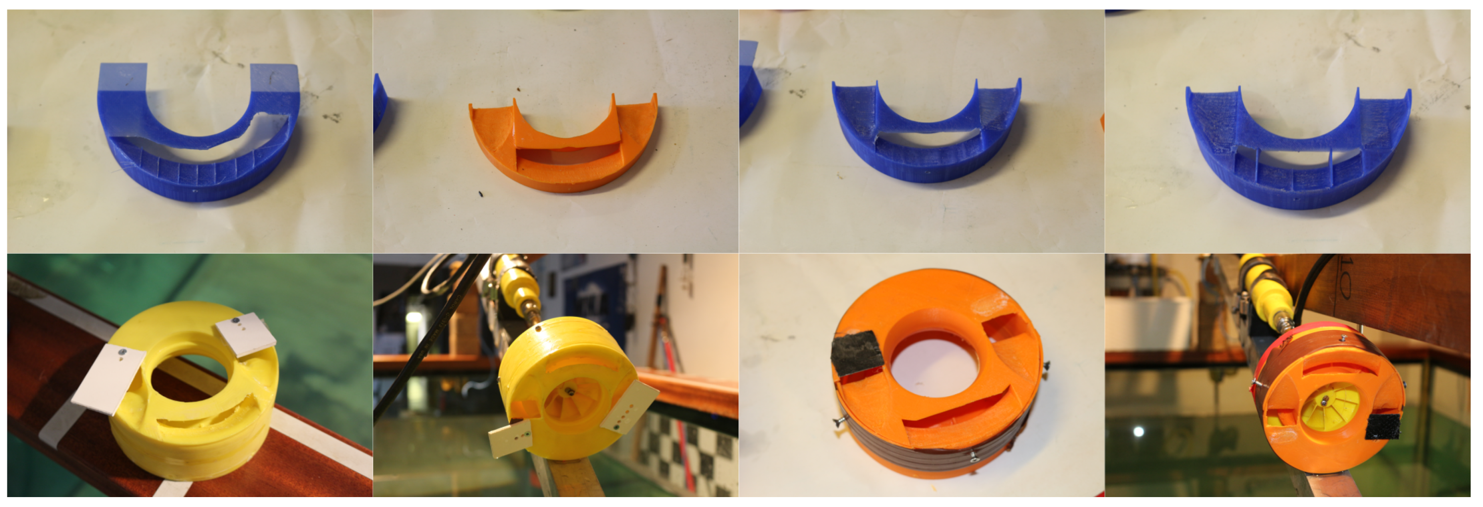
As shown in
Figure 16, 3D printing allowed us to modify quickly and test a significant number of outlet sections and impellers.
5.1. Test Results
As mentioned above, this article only describes tests conducted in the final configuration of the PJM. Testing results reported here were produced with a diameter of mm, a impeller with an external mean diameter of mm, and an asymmetrical outlet geometry with a symmetrical central nozzle and asymmetrical lateral nozzles with a ratio of between one side’s and the other side’s outlet section area. The bigger outlet was the one that was directly invested in due to the positive speed of the rotational component of the fluid flow produced by the impeller. The ratio between pump inlet and outlet areas was about 2.5 with 2200 mm at the inlet and 900 mm at the outlet.
5.2. Bollard Pull Tests
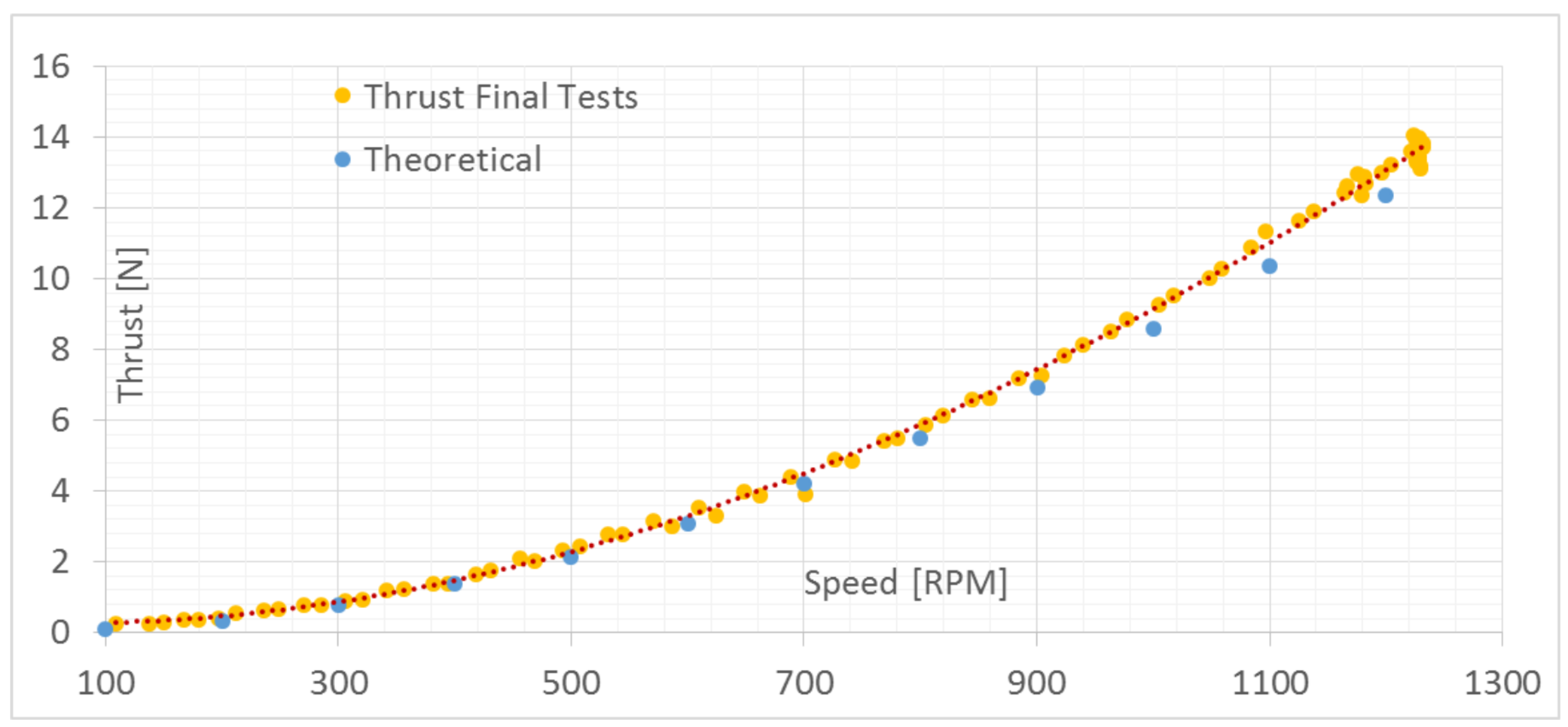
While a huge number of data were obtained by varying some of the above-mentioned parameters, in this section, we provide graphs of the results of bollard pull thrust tests in the final configuration of the PJM thruster.
The main results are reported in the thrust vs. motor RPM graph in
Figure 17, where the experimental results are compared with theoretical expected values. This graph shows that results matched satisfactorily. This graph is important since this curve was used from the control unit to create a match between thrust and reference voltage value used to command the motor, which is strictly related to the motor’s RPM.
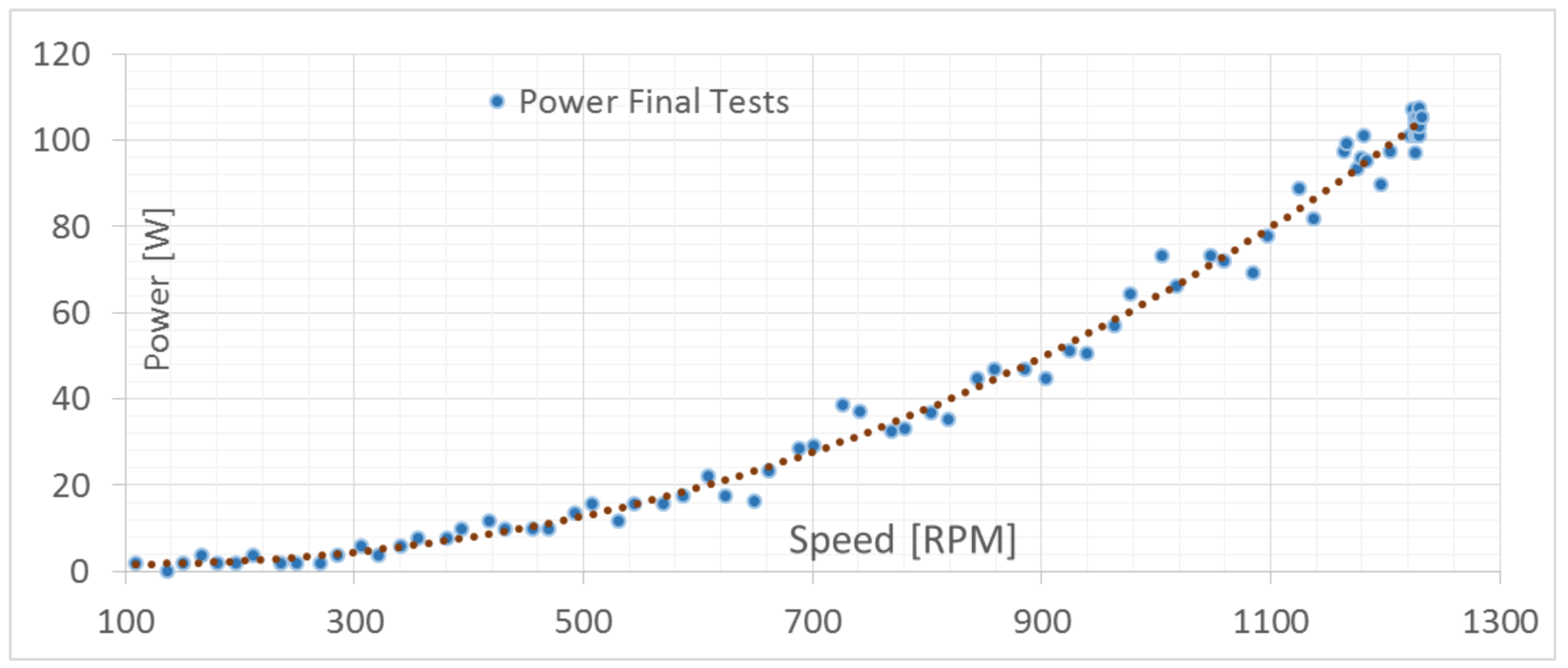
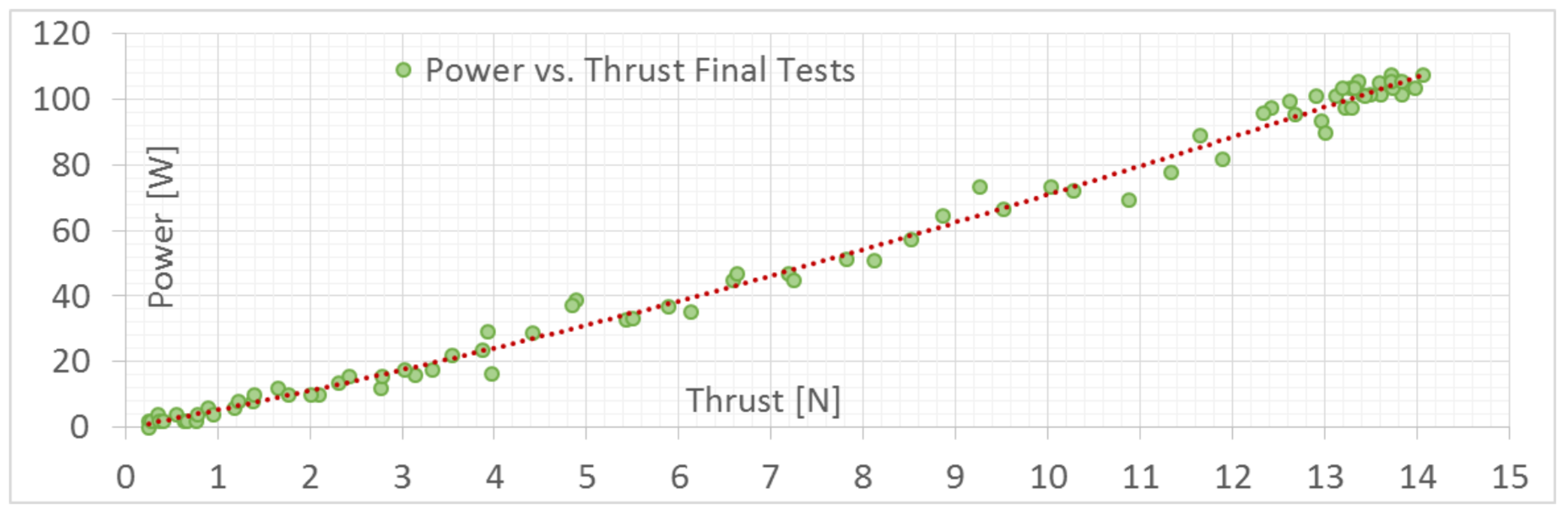
For the same tests, power vs. motor RPM values are shown in
Figure 18 and power vs. thrust values are shown in
Figure 19, indicating that the maximum achievable power was around 105 W for a thrust of about 13.5 N. This power value was less than the 120 W that could be supplied by the motor in the case of necessity.
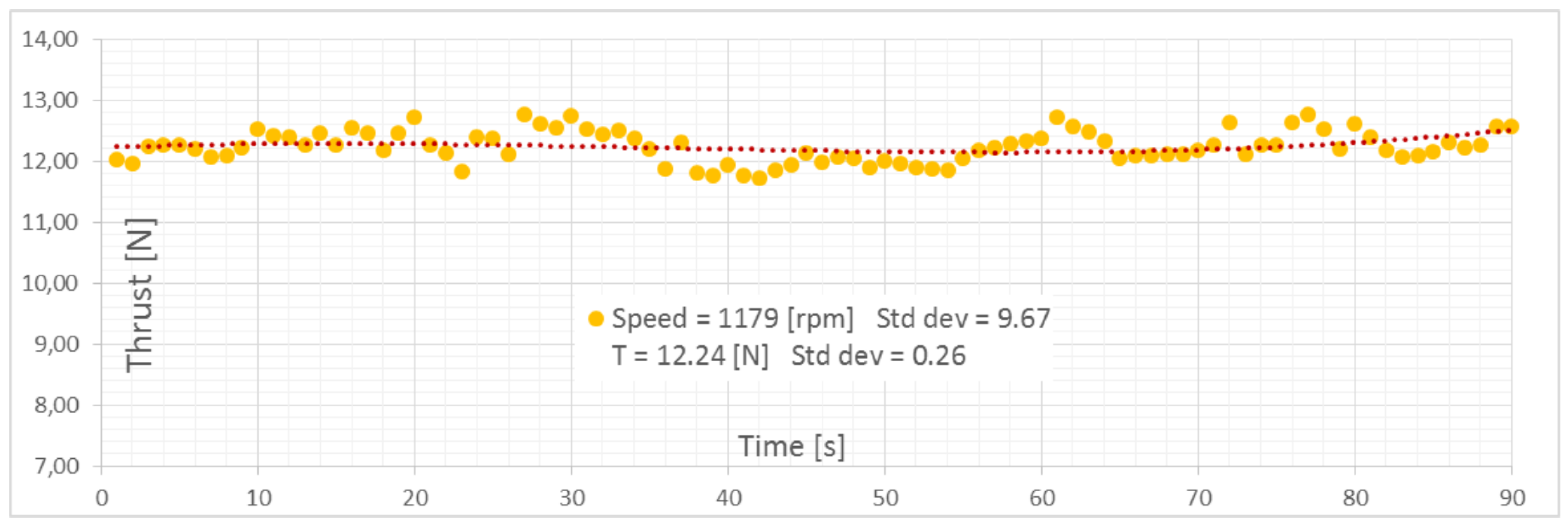
Figure 20 shows a continuous acquisition of thrust around the design value of
N with a standard deviation of
and a speed of the motor of 1179 RPM with a standard speed deviation of
.
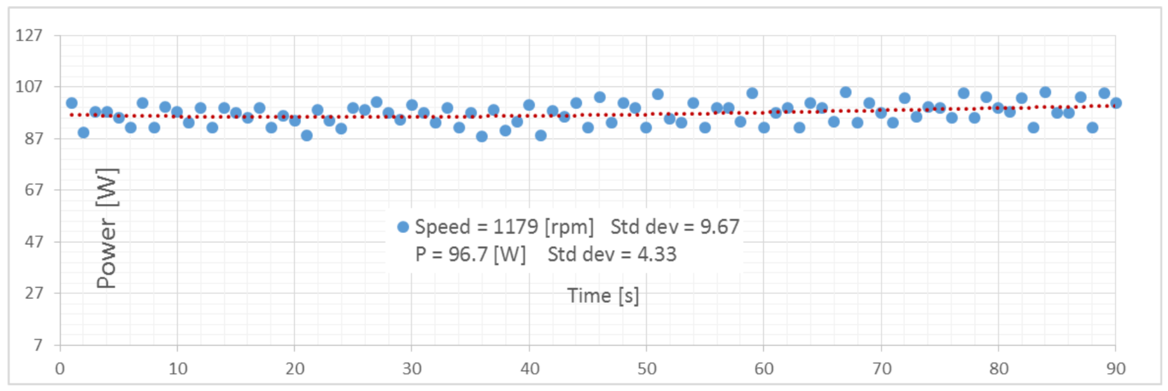
Power absorption at this thrust value is shown in
Figure 21, indicating that power consumption was about 96.7 W with a standard deviation of
.
These results are in accordance with expected values listed in
Table 1.
5.3. Bollard Pull Tests at Different Steering Angles
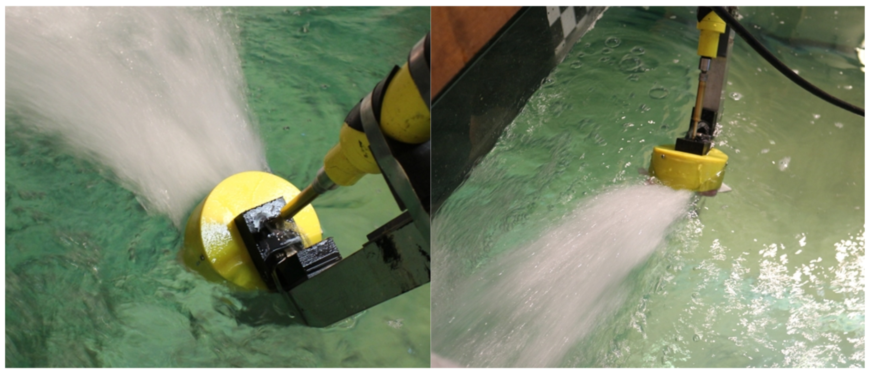
Tests were performed at various angles. The results of these tests showed the exact angles at which the thruster yielded maximum thrust. The final assembly of the PJM implemented for the tests is shown in
Figure 22.
If
is the steering angle when
, which is defined as the angle that divides the central outlet into equal parts, as shown in
Figure 23, since the rotation caused by the impeller naturally induces a tangential component as part of the outlet flow (visible in
Figure 24); as a consequence, thrust reaches its maximum value at an angle that is not zero. The results of these tests are shown in the figure below.
The authors performed tests from
deg–
deg at
deg steps, but for clarity, only some of the data are shown in
Figure 23. Using a mono-component load cell, we measured the forward thrust component
in the x direction (ahead of the motion of the vehicle when
). Maximum thrust
was set at
deg; this means that thrust had a non-0
component in the y direction when
. This component can be checked by performing tests at
deg and
deg. While at
deg, it was not possible to measure any thrust since the cell was unloaded, at
deg,
was clearly non-zero. In this way, we were able to determine whether it was possible to correct the thrust angle through the values of this
.
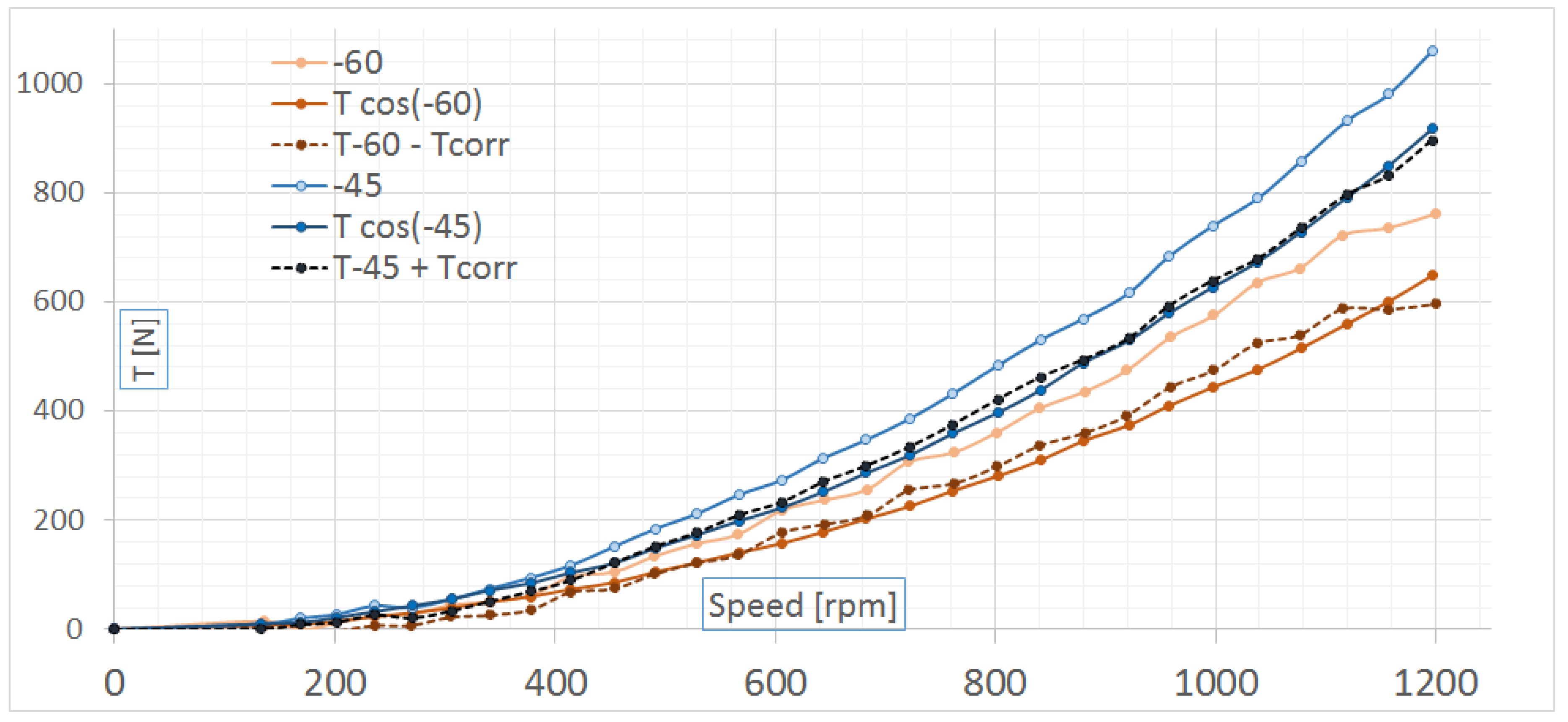
Figure 25 shows two thrust curves at
deg and at
deg. These were compared with thrust curves at zero multiplied by the cosine of
, which is the value of
at an angle
. By comparing this curve with the
deg and
deg curves obtained during the tests, we determined that superimposing the values was not possible. However, when the above-mentioned angle correction was applied, the resulting curves were reasonably superimposable on the original curves. Since the following curves were superimposable when paired:
deg and
deg,
deg and
deg,
deg and
deg, and
deg and
deg, the new
can easily be identified. For the PJM, the above-mentioned correction was taken into consideration when designing control strategies, and
was set at
.
6. Conclusions and Future Developments
A newly-designed modular thruster was developed based on the pump-jet, a solution that has already been successfully employed in larger vessels. The authors designed the complete thruster module from basic equations by re-evaluating existing pump design and constructed four azimuth thrusters for new ASVs, which were purposely designed to work in extremely shallow waters, down to only a few centimeters in depth. These thrusters were built at the CNR-INM laboratories in Genova and tested in a small pool using a custom-made testing rig. Test results were satisfactory, and after calibration of the outlet nozzle geometry, the system met the initial requirements. A summary of the main characteristics of the system is provided in
Table 4.
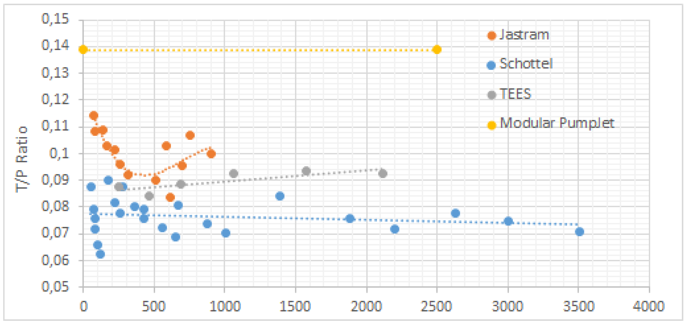
Using the equations the authors adopted for designing the PJM, it was possible to estimate the expected power consumption of a larger version to compare the module with existing, more powerful large-sized systems. The system’s efficiency and power consumption seemed to be in accordance with the parameters given by industrial manufacturers.
In
Figure 26, the PJM ratio between thrust (kN) and Power (kW) is compared with industrial pump-jet units; the value of the
ratio is shown in the abscissa and the value of power (kW) in the ordinate. This graph shows that the
ratio of PJM was a bit higher than the equivalent ratio in larger versions. Conversely, small compact systems usually present problems related to scaling and losses due to finishing and manufacturing, which in general lead to lower thrust and power values. Future analysis of the system will focus on loss of thrust due to at-speed testing, with the thruster positioned in different parts of the hull (bow and stern) of an ASV. Further studies will be conducted on the outlet geometry, and thrust optimization will be analyzed. CFD simulations can help in optimization and in the design of modified versions of the outlet nozzle, which can be carried out very effectively using 3D printing techniques, already used in this work.
For dissemination of results, a complete analysis of all the tests will be provided in future works. Interesting results are foreseen from the adoption of new navigation and guidance techniques in vehicles equipped with four PJM azimuth thrusters.


