Article

Using Flexible Blades to Improve the Performance of Novel Small-Scale Counter-Rotating Self-Adaptable Wave Energy Converter for Unmanned Marine Equipment

1
College of Mechatronics and Automation, National University of Defense Technology, Changsha 410073, China
2
Aerospace and Civil Engineering, School of Mechanical, University of Manchester, Manchester M17JR, UK
*
Authors to whom correspondence should be addressed.
J. Mar. Sci. Eng. 2019, 7(7), 223; https://doi.org/10.3390/jmse7070223
Submission received: 21 June 2019 / Accepted: 11 July 2019 / Published: 15 July 2019
(This article belongs to the Section Ocean Engineering)

Abstract

:
Unmanned marine equipment has been increasingly developed for open seas. The lack of efficient and reliable power supply is currently one of the bottlenecks restricting the practical application of these devices. In order to provide a viable power supply method for unmanned marine equipment, such as sonic buoys and sea robots, we originally propose a novel small-scale flexible blade wave energy converter (WEC) based on self-adaptable counter-rotating operation mechanism. The flexible blade WEC is designed on the basis of the rigid blade WEC with the caging device. This paper identifies the key factors affecting WEC performance through theoretical analysis. According to the numerical simulation analysis, the output mechanical power of the double-layer absorber is 12.8 W, and the hydraulic efficiency is 36.3%. The results of the verification experiment show that the peak power of WEC is 5.8 W and the average power is 3.2 W. The WEC with 65Mn flexible blade under most experimental conditions has the best performance when the blade thickness is 0.10 mm. The study shows that the new generation WEC can effectively overcome the excessive fluctuation of the output power of the previous generation WEC. The output power curve of the novel WEC is relatively smooth, which is conducive to its smooth operation and subsequent utilization and storage of electrical energy.

1. Introduction

Due to the rapid development of marine science and technology and the actual demand for marine resources exploitation, a large number of unmanned marine equipment has been developed and gradually entered the commercial stage [1,2,3,4]. This type of marine equipment, such as surface vehicles, marine meteorological buoys, navigation buoys, marine robots, etc., usually need to be moved to change the working place and are mostly oriented to open sea applications [5,6,7]. Steady and efficient energy supply is an urgent problem need to be solved in the practical application of the marine equipment [8]. Most of the current unmanned marine equipment is powered by external cables or internal batteries [9]. The external cable method limits the scope of work of equipment and depends on the external power system [10]. Because of the limited capacity of battery, the internal battery mode limits the single working time and working intensity of equipment, and need to prevent possible leakage pollution [11,12]. Sustainable power supply technology with high energy density is the fundamental guarantee for improving the endurance and working strength of unmanned marine equipment.
As the marine equipment is generally far from the coast and unattended for a long time, utilizing the marine energy around the equipment is hopeful to fundamentally solve the power supply problem. Wave energy is a kind of marine energy with high energy density and wide distribution, so it is an ideal energy source for power supply. Wave energy began to attract worldwide attention in the 1970s, during which two oil crises triggered an upsurge of research on alternative energy sources [13,14]. The third oil crisis around 1990 and the restrictions on carbon dioxide emissions in the Kyoto Protocol signed in 1997 once again pushed the study of renewable energy to a climax [15]. In the last 20 years, wave energy technology has gradually matured and some of its achievements have been commercialized. Different from mature wind power technology, there has not been a wave energy extraction technology recognized globally and having comprehensive technological superiorities so far [16,17,18,19]. The Penguin horizontal pendulum device of Wello Wave Energy Company (Espoo, Finland) has undergone a full-scale grid-connected power generation test in the Orkney Scotland since 2012. During this time, the device has survived several storms with up to 18 m-high waves [20,21]. The Wave energy extraction device ISWEC (Inertial Sea Wave Energy Converter) of Wave for Energy Srl Company of Italy which is based on gyroscopic inertia effect has completed its full-scale prototype test at the Island of Pantelleria, with rated power 100 kW and Technology Readiness Level of 7 [22,23]. The RAY series of wave power systems developed by Columbia Power Technologies, Inc. (Corvallis, OR, USA) for marine applications have been tested several times in a real marine environment [24]. The RAY series have helped the company successfully obtain funding from the US Department of Energy for the next-generation marine energy device research projects [25].
It can be seen that the current wave energy research mainly focuses on the development of large-scale wave energy converter (WEC) powering grid and off-grid application [16,26,27]. Most of these traditional large-scale WECs require mooring, and the size of the device is relatively larger. However, the power requirements of marine equipment are relatively small, and most of them work in the open sea [7], so it is difficult to directly apply the existing wave energy technology mentioned above.
The WEC involved in this paper needs to be integrated into low-power consumption marine equipment as a power supply module, so its size should not be too large. In many types of WEC, the size of point absorber is the smallest relative to the wavelength of incident wave [28]. Due to the relatively small size of the surface buoy of the point absorber, its performance characteristics are not sensitive to the propagation direction of wave on the sea surface [17,29]. The above working characteristics of point absorber are very suitable for unmanned marine equipment with limited installation space and inconvenient adjustment of motion posture. Typical application products of point absorbers are PowerBuoy series of Ocean Power Technologies [30] in the United States and AquaBuOY series of Finavera Renewables [31] in the UK. The surface buoy of the PowerBuoy PB3 responds to the wave motion to produce a linear reciprocating motion relative to the damper plate and converts this linear motion into the rotational motion required by the generator through a built-in mechanical system that includes a ball screw, as shown in Figure 1. Its buoy diameter is 2.65 m and its overall height is 13.3 m. The current point absorber still takes high sea states as its working background, and its application goal is to develop large-scale devices. However, such applications do not fully exploit the performance advantages of small point absorber in simplifying structure and improving efficiency.
In view of the potential application prospects of point absorber-type WEC in the field of power supply for low-power unmanned marine equipment and the technical obstacles restricting the existing point absorber to directly serving as the power supply module of marine equipment, we have originally developed a rigid blade WEC with caging device, as shown in Figure 2a. Our research group theoretically analyzed the mechanical relationship between the surface buoy and Power Take-off (PTO) system of the point absorber-type WEC and carried out numerical analysis and experimental verification on its key system parameters [32]. The research group also conducted a theoretical study on the effects of different types of surface buoys on WEC performance characteristics. The constitutive relations of wave forces, motion and geometric parameters of surface buoys with different geometric shapes were constructed, and the capture efficiency of wave energy of various types of surface buoys was investigated [33].
In the verification experiments, we found that the rigid blade WEC could adapt well to the wave motion, drive the upper and lower absorbers to generate electric energy. However, when the WEC moves to the peak or trough position, there is a process in which the blades need to change deflection direction. During this time, the WEC cannot absorb the wave energy, and the output power is temporarily zero. This phenomenon undoubtedly reduces the average power, and causes the torque load fluctuation of the WEC, which reduces the reliability of the WEC during operation.
In nature, fish use flexible fins made of pterygiophore and skin in swimming to improve its propulsion efficiency and mobility [34,35]. Inspired by the flexible structure of the fin, our research group re-analyzed and re-designed the previous generation of the small WEC, and originally proposed a novel small flexible blade WEC, as shown in Figure 2b. The research in this paper shows that the flexible blade WEC can effectively overcome the excessive fluctuation of the output power of the rigid blade WEC, smooth the output power curve, and improve the self-adaptive power generation ability of the WEC under low sea conditions. Theoretical analysis, numerical simulation and verification experiments were carried out on the hydrodynamic characteristics of the modified flexible blade WEC in this paper. The performance characteristics and advantages of the flexible blade WEC were also comprehensively analyzed.
The remaining chapters of this paper are organized as follows: Section 2 introduces the structural improvement, conceptual design and working principle of the new WEC; Section 3 theoretically analyzes and numerically simulates the performance characteristics of the new WEC, especially its flexible blades; Section 4 presents the verification experiments of the WEC; Section 5 draws the conclusions for the study.

2. Conceptual Design and Implementation of Flexible Blade WEC

2.1. Initial Design of Rigid Blade WEC and Expected Application

Since the main working place for unmanned marine equipment is the deep and open sea, WEC, as its energy supply module, is not allowed to obtain the relative motion reference body by fixing on the seabed. At the same time, limited by the installation space inside the unmanned marine equipment, the smaller the size of the WEC, the easier it is to integrate into the equipment. Therefore, external moving parts such as damper plates or the like which can significantly increase the size of the power supply module are also not recommended.
Based on the surface wave characteristics of the ocean waves and the demand characteristics of unmanned marine equipment, we have developed a new type of small rigid blade point absorber type-WEC, as shown in Figure 3a. The WEC mainly includes seawater surface part and underwater part, which are connected by stainless steel cable. The surface part, namely surface buoy, is acted upon by unmanned marine equipment. It responds to the wave motion to drive the WEC to generate heaving motion. The underwater part mainly consists of a small generator, a double-layer absorber, an additional weight ball, and other necessary transmission mechanisms. The single layer absorber is mainly composed of an inner ring, an outer ring, a number of rigid blades, blade connecting rods and blade caging devices. The rigid blades of the absorber are centrally symmetric circumferentially distributed and can be rotated within the angle range allowed by the caging devices. When the blade is impacted by the water flow, a circumferential torque to the absorber is generated. The unique feature of the new WEC is that the direction of the circumferential torque generated by the rigid blade does not change, whether the blade is deflected upwards or downwards. The new small-scale WEC is expected to provide a new means of energy supply for unmanned marine equipment.
The working process of the rigid blade WEC is shown in Figure 3b. The WEC rises and falls under the combined action of the surface buoy and its own gravity. The blade will self-adaptively change the deflection direction according to the water flow impact to maintain a permanent unidirectional torque to the absorber. The blades of the upper and lower absorbers are arranged in opposite directions and are fixedly connected to the stator and rotor of the generator, respectively. Therefore, the double-layer absorber can provide the embedded generator with the counter-rotating motion required for power generation.
The small WEC is simple in construction and compact in size, and its operation is not limited by the amplitude of the heave motion. It requires no additional components such as mooring and damper plates. Therefor the WEC has the potential to develop into a small multi-purpose mobile power supply system. We also intend to use it as the power supply module of the mobile ocean platform and the module of the offshore wave energy arrays in the long-range plan.

2.2. Using Flexible Blades to Replace Rigid Ones

Comprehensive theoretical research and experimental verification on the rigid blade WEC was conducted. The research results verify the rationality of the working principle and the influence of key factors on performance characteristics [32]. However, we found that the output power of the WEC is always intermittently zero in the experiments, which leads to excessive fluctuation of the output power curve of the rigid blade WEC, as shown in Figure 4. This phenomenon obviously has a negative impact on the subsequent utilization of electric energy and the torque load during operation.
It can be seen from the operation process of the rigid blade WEC that the WEC changes its blade directions to adapt to the change of flow impact at the crests and troughs, that is to say, there is a process in which the blade deflection direction changes, as shown in Figure 5. During this process, the blade does not contact the caging device, and no torque can be generated to push the absorber to rotate. Only when the blade is deflected to the corresponding direction of the water flow impact and contacts the caging device, it can continue to push the absorber to rotate. Therefore, during the blade commutation, the absorber cannot provide the counter-rotating motion required by the generator, which results in a phenomenon that the WEC output power is temporarily zero.
In nature, fish use fins in swimming to improve their mobility and propulsion efficiency. Inspired by the flexible structure of the fish fin, we decided to use flexible blades to replace rigid ones to design a novel flexible blade WEC. As shown in Figure 6, the elastic characteristic of the flexible blade itself is used to replace the caging device of rigid blade to realize the self-adaptable deflection and angle limit of the blade. Since the caging device is eliminated, as long as the flexible blade is deformed by the water flow impact, the torque to the absorber will be generated. In theory, this kind of design philosophy can minimize the time in which the WEC output power is zero.

2.3. Structural Implement and Working Principle of Flexible Blade WEC

The main difference between the new generation of flexible blade WEC and the previous generation of rigid blade WEC is that the caging device is eliminated, and the flexible blade is used instead of the rigid blade. As shown in Figure 7, the WEC includes a surface buoy and an underwater PTO. The surface buoy can be replaced by unmanned marine equipment, transforming wave motion into WEC’s heaving motion. The underwater PTO mainly includes a small generator, a double-layer absorber, an additional weight ball, and other necessary transmission mechanisms, and the outer ring has a diameter of 400 mm.
The novel flexible blade WEC is based on the self-adaptable counter-rotating operation mechanism, and its working process is shown in Figure 8. Due to the unique characteristics of the self-adaptable deflection of the flexible blade against water flow impact, the single-layer absorber maintains a unidirectional rotational motion regardless of rising or sinking during the heaving motion. The upper and lower absorbers convert the heaving motion of WEC into the counter-rotating motion required by the generator to generate electricity.
According to the working characteristics of the novel flexible blade WEC, the flexible blade cannot provide thrust only when it is in a planar shape at the wave peak and trough. Once the bending deformation of flexible blade occurs, the thrust will be generated and the torque to the absorber will be formed. However, the rigid blade WEC can only provide thrust when its blades are deflected to the caging device, and the blade cannot provide thrust during the commutation process. Compared to the case of rigid blade, the time period when flexible blade cannot provide thrust is much shorter. Therefore, the flexible blade helps to smooth the output power curve and improve the self-adaptable power generation capability under different sea states, especially in low sea state.

3. Theoretical and Numerical Analyses of Performance Characteristics

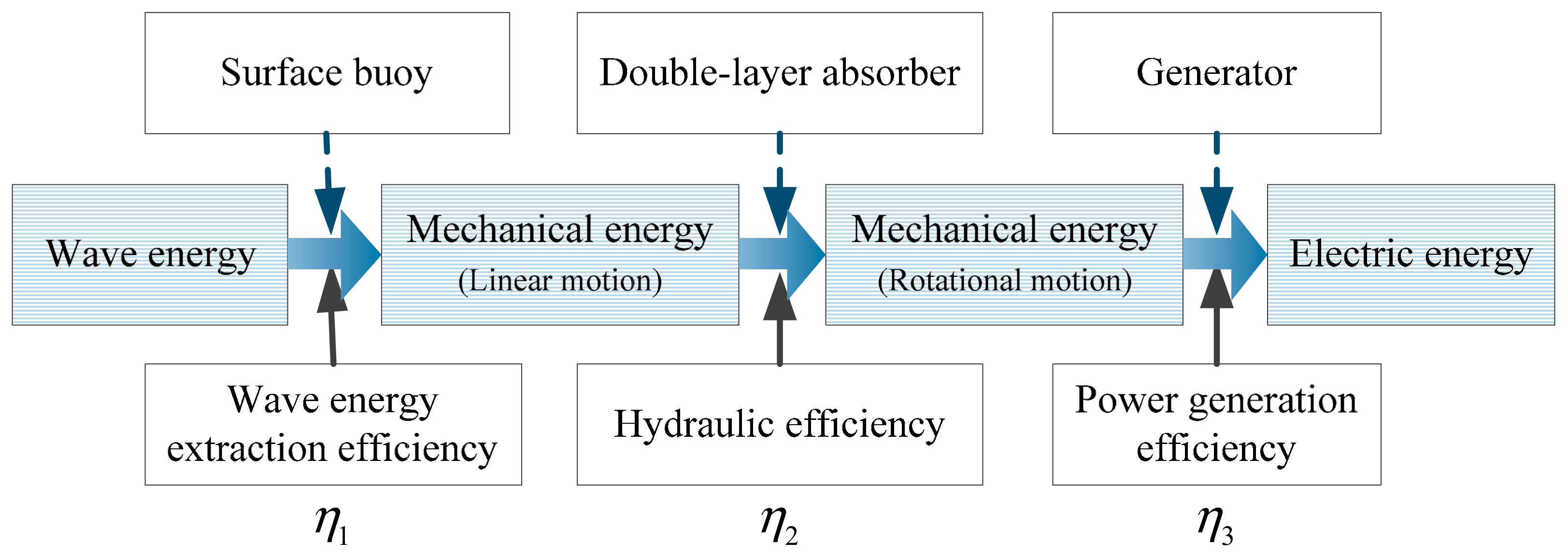
3.1. Analysis of Output Power and Efficiency Characteristics of the Absorber

Figure 9 shows the energy conversion process of the WEC. The WEC converts the wave energy into mechanical energy in the form of linear motion through the heave motion of the surface buoy, and then converts it into mechanical energy in the form of rotational motion through the double-layer absorber, finally drives the generator to produce electricity.
From the above analysis, the overall efficiency η of the small WEC involves the wave energy extraction efficiency ηext of the surface buoy, the hydraulic efficiency ηhyd of the double-layer absorber and the power generation efficiency ηpow of the small generator, namely:
η =   η e x t η h y d η p o w
Among them, ηext is an important characteristic parameter of WEC surface buoy, which has been studied in detail by our research group [33]. Generator is a standardized industrial product with mature technology, and its performance characteristics were fully studied. For small generators, reasonable selection, transmission ratio, and sealing treatment are the urgent problems that need to be solved in the current WEC engineering. Therefore, this paper mainly focuses on the hydraulic efficiency ηhyd of the double-layer absorber. It should be noted that when the surface buoy converts wave energy into mechanical energy in the form of linear motion, the surface buoy is subjected to the tensile force of the PTO through the tether, so ηext and ηhyd are not independent of each other.
The input power Pin of the double-layer absorber can be calculated by the following equation:
P i n = E i n t = 1 2 ρ π R 0 2 h V A 2 t = 1 2 ρ π R 0 2 V A 3
where the Ein is the kinetic energy of a cylindrical fluid with height of h and radius of R0 passing through the horizontal cross-section of the absorber in time of t. From the numerical simulation of the flow field around the rigid blade WEC [32], it can be seen that the double-layer absorber has a significant influence on the flow field in the range of 1.5 times its own radius R, so the radius of the cylindrical fluid R0 = 1.5R is appropriate.
The output mechanical power Pout of the double-layer absorber is:
P o u t = 1 + S T ω = 1 + S N T S ω
where S is the influence coefficient of a single-layer absorber located upstream of the impinging water flow to that located downstream, generally 0 < S < 1, T is the output torque of the single-layer absorber, ω is the rotational speed (rad/s), N is the number of blades of the single-layer absorber, and TS is the torque generated by the single blade to the rotating shaft of the absorber.
The hydraulic efficiency ηhyd is defined as the ratio between the output power Pout of the absorber and the input power Pin of the absorber:
η h y d = P o u t P i n = 1 + s N T S ω 1 2 ρ π R 0 2 V A 3 = 2 1 + s N T S ω ρ π R 0 2 V A 3
It can be seen from Equations (3) and (4) that the output power Pout and hydraulic efficiency ηhyd of the double-layer absorber involve many variables, such as the output torque of the single-layer absorber T, and the torque generated by the single blade to the rotating shaft of the absorber Ts, and the rotational speed of the absorber ω, and the like. In order to clarify the quantitative values of the above variables and their influence on the performance characteristics of the WEC, a combination of theoretical analysis and numerical simulation was adopted to study them.

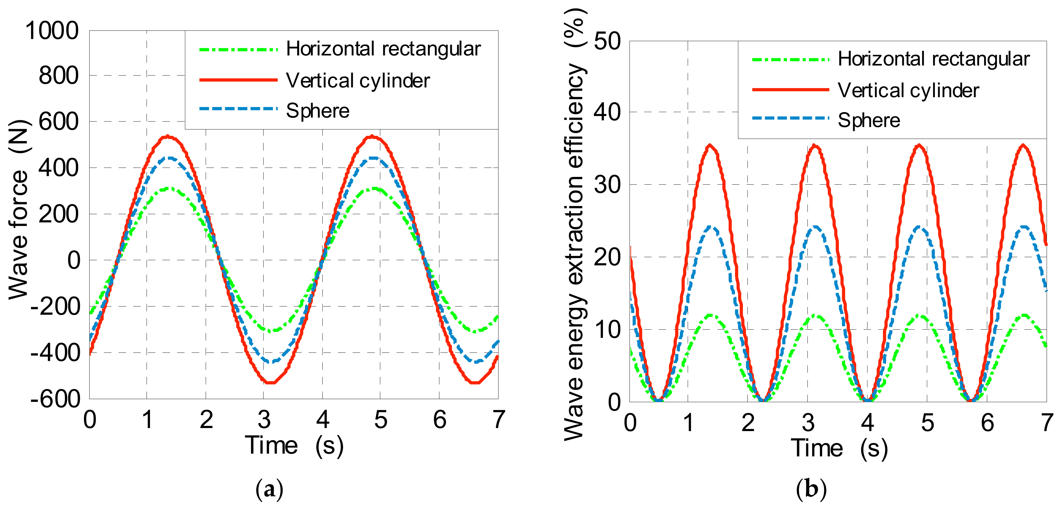
3.2. Preliminary Analysis of Factors Affecting the Performance of WEC

As the first step in the energy conversion process of the WEC, the surface buoy converts wave energy into mechanical energy in the form of heave motion. The surface buoy is in direct contact with the sea surface waves and is affected by the wave radiation-diffraction effect. Based on the existing research basis [33], the energy conversion characteristics of surface buoy are preliminarily studied and evaluated.
Assuming that the water around the surface buoy is non-viscous, irrotational and incompressible, and considering the interaction of wave motion and surface buoy, the dynamic equation of the surface buoy can be expressed as [33,36]:
m X ¨ ( t ) = G S ( t ) P ( t ) n d S Q I + F PTO ( t ) = G + F F K + F D + F R + F PTO
where m is the mass of the self-adaptable counter-rotating WEC, X is the heaving displacement of the buoy from its hydrostatic equilibrium position, X ¨ is the heaving acceleration of the buoy, G is the gravity of the buoy, S is the submerged surface area of the buoy, P is pressure, n is the unit normal vector of the submerged surface of the buoy surface of the buoy, Q is the viscous damping force, I is the inertial force of the additional mass, FFK is the Froude-Krylov force, FD is the diffraction force, FR is the radiation force, and FPTO is the damping force of underwater PTO.
The calculation method of FFK assumes that the original wave pressure distribution of the incident wave field does not change by the presence of the buoy [37]. First, the force of the undisturbed incident wave pressure on the floating body can be calculated. Then, a diffraction coefficient C reflecting the additional mass effect and the diffraction effect is multiplied to correct the C value, which is determined by the model test. The expression of FFK is as follows:
F F K = C S ( t ) P n d S
The input energy PIN of the incident wave within the width of the surface buoy is as follows:
P I N = ρ g H 2 ω 16 k 1 + 2 k d sinh 2 k d B
where ρ is the seawater density, ω is the circular frequency of the incident wave, k is the wave number, d is the water depth, and B is the heading wave width of the surface buoy.
The output power POUT of the surface buoy can be expressed as the time average value of its mechanical energy output during the wave motion period T, that is:
P O U T = 1 T t t + T F V d t = 1 T t t + T C S ( t ) P n d S + B P T O X ˙ X ˙ d t
where F is the wave force, V is the velocity of the surface buoy, and BPTO is the damping coefficient of the underwater PTO.
The energy capture width ratio of the surface buoy, that is, the wave energy extraction efficiency ηext is as follows:
η e x t = P O U T P I N = 1 T t t + T C S ( t ) P n d S + B P T O X ˙ X ˙ d t ρ g H 2 ω 16 k 1 + 2 k d sinh 2 k d B
Based on the above constitutive relations and energy conversion equations for the characteristic parameters of surface buoy, the wave force and wave energy extraction efficiency of the multi-type surface buoy were numerically calculated under the wave motion with wave height of 0.3 m and period of 3.5 s, as shown in Figure 10. The results show that the vertical cylindrical buoy has better hydrodynamic characteristics and higher wave energy extraction efficiency than horizontal rectangular and spherical buoys.
The absorption and conversion of wave energy by the new WEC mainly utilizes the response of the surface buoy to the vertical component of the wave motion. However, the wave motion also has a horizontal component, and the horizontal component causes the buoy to undergo lateral displacement while doing the heave motion, and thus affects the operation of the underwater PTO.
According to the surface gravity waves theory [38], the trajectory of the water particle of the sea surface can be approximately regarded as a circle. Assuming that the trajectory of the buoy is consistent with that of the surface water particle, the horizontal component of the wave motion has the greatest influence on the movement of the buoy, and its interference to the operation of the underwater PTO is also the largest. Figure 11 shows the relationship between wave motion and surface buoy and underwater PTO of the WEC [32]. The buoy passes through a1–d1 sequentially during a wave motion cycle. The surface float is connected to the underwater PTO by a tether, and the tension of the tether can be maintained by increasing the counterweight and optimizing the layout of the underwater blade [39,40]. The underwater PTO is far from the fluctuation of the sea surface, and the angle θ at which the underwater PTO is dragged by the tether fluctuates in a small range near the vertical direction. Therefore, it can be considered that it sequentially passes through a2–d2 in one wave motion cycle.
Affected by the horizontal component of the wave motion, the surface float will produce a lateral motion with large amplitude. The lateral motion may cause a large fluctuation in the velocity V of the PTO heave motion and the dragging angle θ of tether. Assuming that the time average velocities of the underwater PTO in the two motion stages a2–b2 and b2–c2 are V1 and V2, respectively, the ratio K of the two phases is used to measure the velocity fluctuations.
The K value can be calculated from the following formula [32]:
K = v 1 v 2 = l 2 r 2 ( l r ) ( l + r ) l 2 r 2 × 100 %
where l is the length of the tether and r is the amplitude of the wave motion.
Wave height h is one of the important wave parameters, replacing r with h, h = 2r. The ratio of the length l of the tether to the wave height h is defined as R, i.e., R = l/h. So,
K = v 1 v 2 = 4 R 2 1 2 R + 1 4 R 2 1 + 2 R + 1 × 100 %
It can be seen from Figure 11 that the instantaneous angle θ of the buoy dragging the PTO through the tether is as follows:
θ = a r c s i n 1 2   c o s ( 2 π T t + π 2 ) R
The maximum value of the instantaneous angle θ occurs at the maximum amplitude of the lateral motion of the buoy, i.e., at b1 and d1. Therefore, the maximum angle θmax of the tether dragging PTO is:
θ m a x = θ b 1 = a r c s i n 1 2 h l = a r c s i n 1 2 K
Calculated by the Equations (11) and (13), when R = 10, K = 95.1%, θmax = 2.9°. That is, when the length l of the tether is 10 times the wave height h, the average velocity of the underwater PTO during the a2–b2 motion stage is 95.1% of the b2–c2 stage, and the velocity fluctuates within 4.9%; the angle at which the PTO is dragged by the tether from the vertical direction varies within ±2.9°. Therefore, a reasonable length of the tether can greatly reduce the influence of the horizontal component of the wave motion on the motion performance of the underwater PTO.

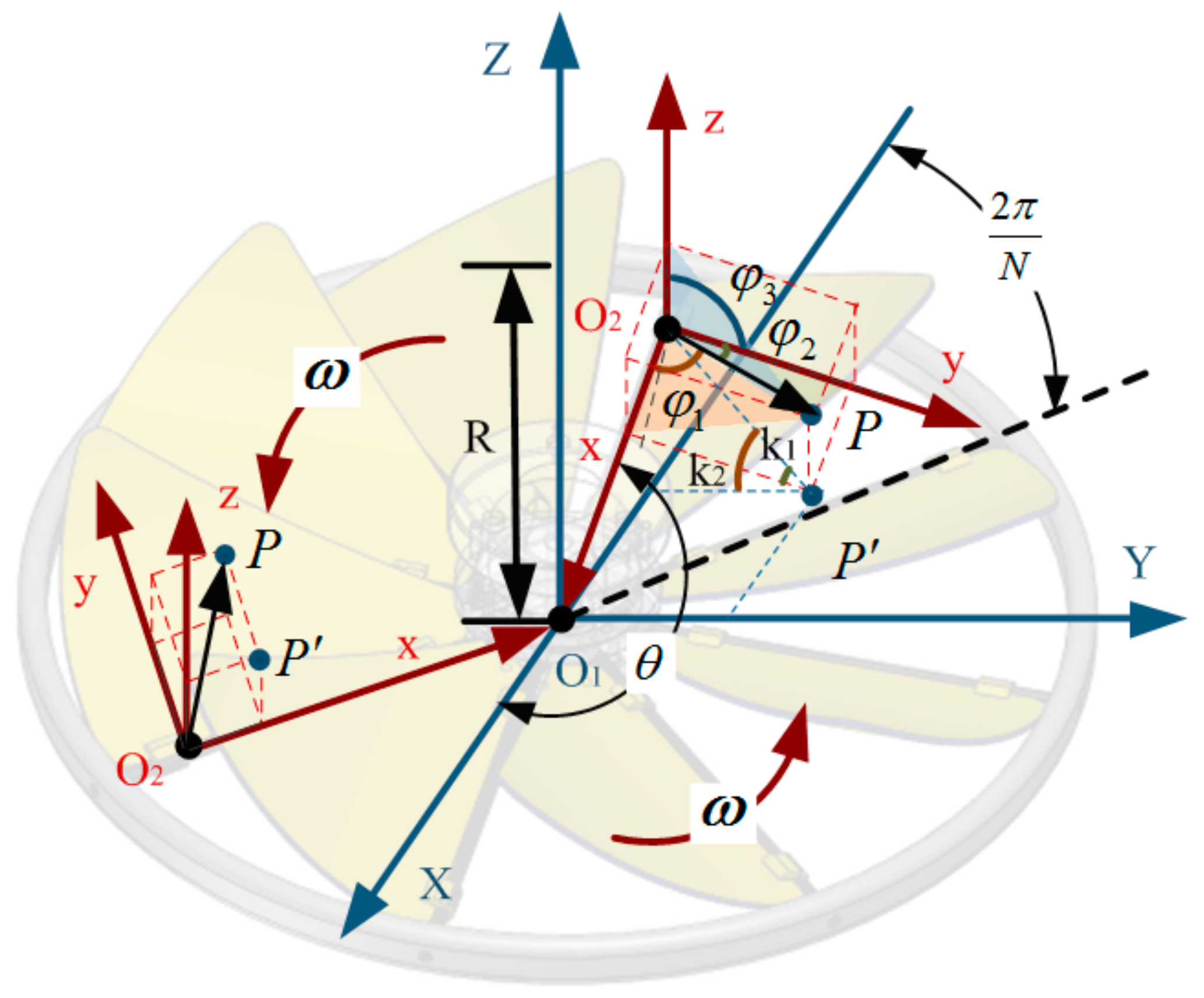
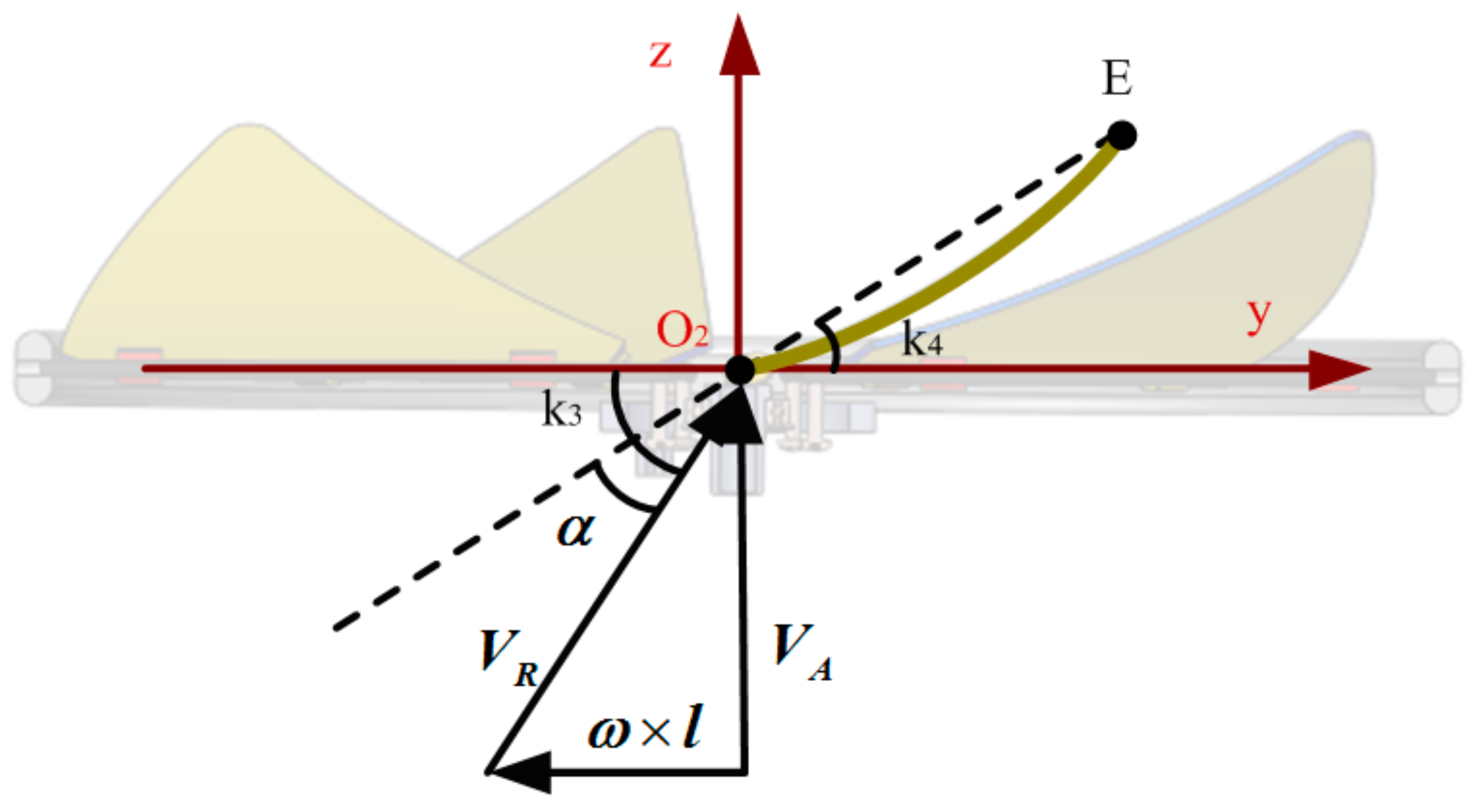
3.3. Theoretical Analysis of Kinematic Characteristics

The upper layer absorber was taken as an example, and its horizontal cross-section was used as a reference plane to establish a global coordinate system O1XYZ, i.e., a fixed coordinate system, as shown in Figure 12. The intersection O1 of the rotating shaft and the reference plane is taken as the origin of the global coordinate system. The X-axis and the Y-axis are radial directions perpendicular to each other in the reference plane, and the Z-axis is the direction in which the rotating shaft is located, perpendicular to the reference plane and vertically upward. A local coordinate system O2xyz, i.e., a moving coordinate system, was established on the flexible blade. The intersection point O2 of the flexible blade chord and the blade connecting rod was taken as the origin of the local coordinate system. The direction of the connecting rod pointing to the rotating shaft is the x-axis, the projection line of the blade chord on the reference plane is they-axis, and the z-axis is perpendicular to the reference plane and vertically upward.
The radius of the absorber is R, the number of blades is N, the azimuth angle is θ, the rotating angular velocity is ω, and its rotating direction is anticlockwise. Then the position coordinates of the local coordinate system origin O2 in the global coordinate system are:
X , Y , Z O 2 = R cos 2 π N cos θ , R cos 2 π N sin θ ,   0
where the azimuth angle θ is an angle formed by the blade connecting rod with the X-axis during the rotational motion, and θ = ω d t .
Assuming that any point on the bending deformed flexible blade is P, the radius vector from O2 to P is r, and its modulus is r, the direction angles corresponding to x,y and z-axis are φ1, φ2 and φ3, respectively. Then the position coordinates of point P in the global coordinate system are:
X , Y , Z P = R cos 2 π N cos θ + r cos φ 1 sin k 1 cos k 2 , R cos 2 π N sin θ r cos φ 1 sin k 1 sin k 2 , r cos φ 3
where cos 2 φ 1 + cos 2 φ 2 + cos 2 φ 3 = 1 ; k1 and k2 are auxiliary angles for simplifying the position representation, k 1 = arctan r cos φ 1 r cos φ 2 = arctan cos φ 1 cos φ 2 , k 2 = π 2 - θ + k 1 = π 2 - θ + arctan cos φ 1 cos φ 2 .
The flexible blade rotates around the rotating shaft of the absorber. Since the distance between each point on the blade and the rotating shaft is not equal, the tangential velocities of their circular motion are not uniform. Because the area near the blade chord is the main contribution area to the torque of the absorber, the vertical section of the blade chord was analyzed, as shown in Figure 13.
Assuming that the relative velocity of the upper absorber and the impacting water flow in the vertical direction is VR0, the rotational speed of the blade is ω, and the radius vector of O2 is l, then the combined velocity VR of the blade relative to the impacting flow is:
V R = V R 0 ω × l
Since VA and ω × l are perpendicular to each other, the modulus VR of VR can be calculated accordingly, as follows:
V R = V R = V A 2 + ω × l 2 = V A 2 + ω 2 R 2 cos 2 2 π N
Assume that the chord endpoint of the flexible blade is E, the radius vector from O2 to E is rE, and its modulus is rE. The direction angles of rE corresponding to x, y and z-axis are φE1, φE2, and φE3, respectively. k3 is the angle between the relative impacting flow velocity VR and the horizontal reference plane, and k4 is the angle between rE and the horizontal reference plane:
k 3 =   arctan V A ω   R cos 2 π / N
k 4   =   arctan r E cos φ E 3 r E cos φ E 2 = arctan cos φ E 3 cos φ E 2
Therefore, the angle of attack of the flexible blade α is:
α =   k 3 k 4   =   arctan V A ω   R cos 2 π / N arctan cos φ E 3 cos φ E 2

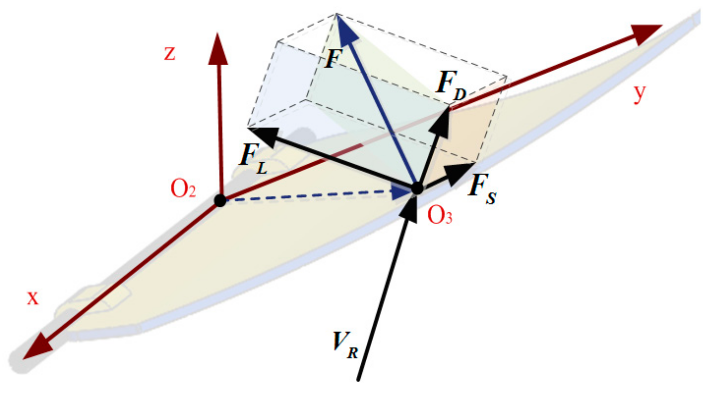
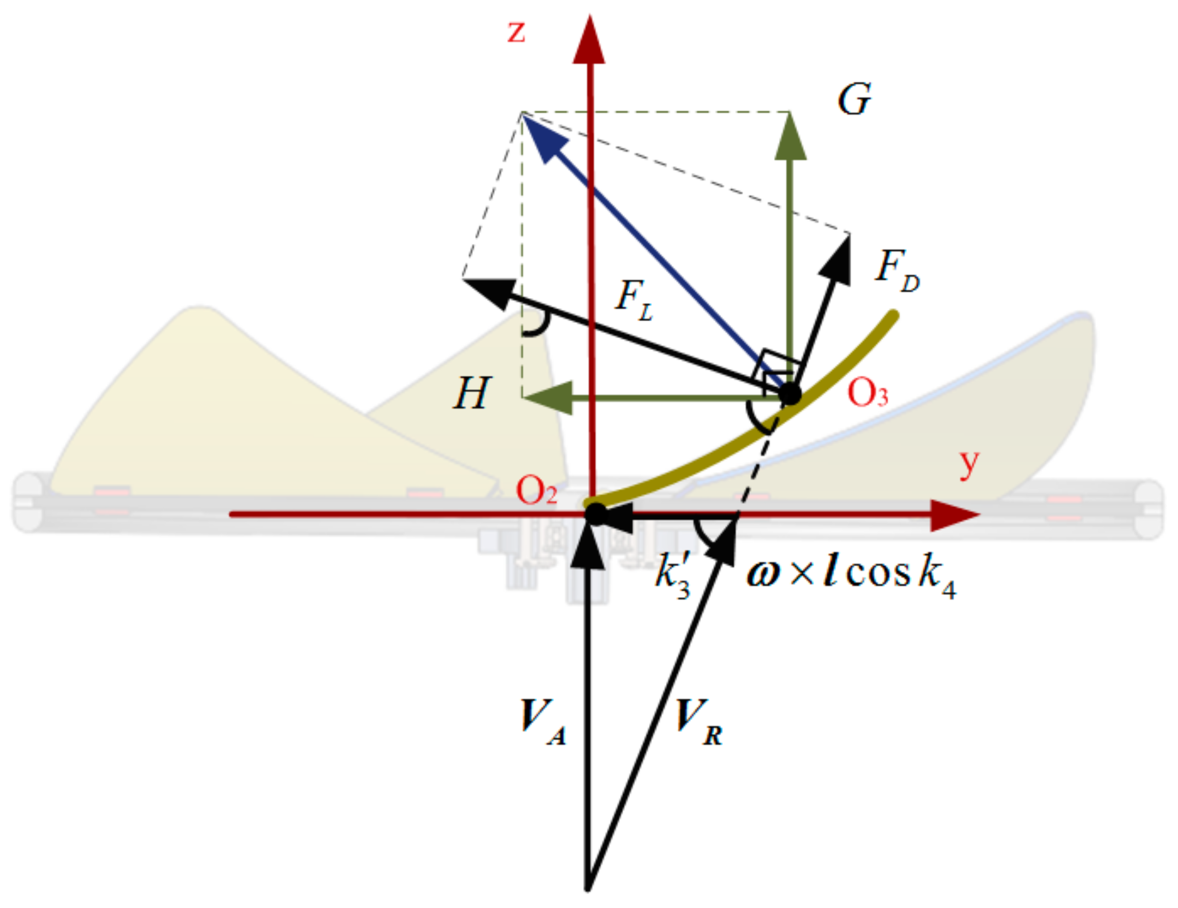
3.4. Theoretical Analysis of Dynamic Characteristic

The double-layer absorber performs both heaving motion and rotational motion during operation. In this process, the magnitude of impact force and the angle of attack of the blade are not constant, and the motion patterns of each point on the blade are also different. In order to facilitate the analysis of the dynamic characteristics of the flexible blade, it is assumed that the equivalent action point of the resultant force F of the impact flow on the blades is O3 (not necessarily on the flexible blades), as shown in Figure 14.
According to the force characteristics of the flexible blade, the resultant force F of the flexible blade is:
F = Δ P ( V R , r , φ i ) d s = F D + F L + F S
where ΔP is the pressure difference between the pressure side and the suction side at each point on the flexible blade, and φi(i = 1,2,3) is the direction angle of the radius vector r of each point corresponding to the three coordinate axes. FD is the blade resistance, FL is the blade lift, FS is the blade lateral force, and the plane where FD and FL are located is perpendicular to the rotating shaft and the blade connecting rod.
The modulus of FD and FL can be obtained by:
F D = F D =   C D 1 2 ρ V R 2 A
F L = F L   =   C L 1 2 ρ V R 2 A
where CD and CL are the drag coefficient and lift coefficient of the flexible blade, respectively. ρ is the seawater density, and A is the projected area of the blade on the plane perpendicular to VR.
The flexible blades of the absorber adopt a centrally symmetric circumferential distribution, so that the lateral forces FS of the different blades can cancel each other out. Therefore, it is only necessary to analyze the component force F’ of the resultant force F in the vertical plane. To facilitate the analysis of the effect of the component F’ on the strength of the rotating shaft and the output torque of the absorber, it was decomposed into the vertical component G and the horizontal component H, as shown in Figure 15.
G , H = F D , F L sin k 3         cos k 3 cos k 3         sin k 3
k 3   =   arctan V A ω × l cos k 4   =   arctan V A ω R cos 2 π N r cos φ 1
where k4 is the angle between the tangential velocity of the circular motion of the point O3 and the plane where FD and FL are located, and k4 can be simplified in the Equation (16).
The torque TS produced by a single blade to the rotating shaft of the absorber is:
T S = H l cos k 4 = ( F L sin k 3 F D cos k 3 ) ( R cos 2 π N r cos φ 1 )
Put TS into Equations (3) and (4), the output mechanical power Pout of the double-layer absorber is:
P o u t = 1 + S N T S ω = 1 + S N ω ( F L sin k 3 F D cos k 3 ) ( R cos 2 π N r cos φ 1 )
The hydraulic efficiency ηhyd of the absorber is:
η h y d   =   P o u t P i n = 2 1 + S N ω ( F L sin k 3 F D cos k 3 ) ( R cos 2 π N r cos φ 1 ) ρ π R 0 2 V A 3
Theoretical analysis can clarify the main factors affecting the performance characteristics of WEC, and it is also the calculation basis for data processing in subsequent numerical simulation and verification experiment. The flexible blade is subjected to bending deformation due to the impact of the water flow, and the continuous deformation of the blade surface, in turn, changes the distribution of the surrounding flow field. At the same time, the influence of the flow field on each point of the blade are not uniform, resulting in a large difference in the deformation of the blade at different positions. The interaction between the blade and the surrounding flow field is essentially a complex two-way fluid-solid coupling relationship [41,42]. In view of the advantages of CFD technology in visualization of flow pattern distribution and quantification of physical parameter distribution [43], numerical simulation method was adopted to partially replace the theoretical calculation to study the mechanical characteristics of blade surface.

3.5. Configuration of Numerical Simulations

ANSYS Workbench version 19.2 was used to numerically calculate the two-way fluid-solid coupling relationship between the flexible blade and the surrounding flow field. Under this software platform, the flow field data in Fluent module and the structure data in Transient Structural module were coupled and transmitted by System Coupling module, and the mechanical characteristics data of flexible blades were obtained by iteration calculation. This numerical simulation method is helpful to capture the detailed information at local features and provide a clear structural optimization solution for improving WEC power and efficiency characteristics [43,44], such as choosing reasonable blade thickness, blade inclination, etc.
The dynamic mesh method was used to realize the shape change of the flow field caused by the deformation of the flexible blades. SST k-ω was adopted as the turbulence model because it combines the excellent computational performance of standard k-ω in the boundary layer adverse pressure gradient region and the good simulation effect of k-ε on the free shear flow region [45]. Pressure-Implicit with Splitting of Operators (PISO) was chosen as the solution scheme for the pressure-velocity coupling equation.
The double-layer absorber contains more detailed structural features, so the flow field shape is complex. The dynamic mesh method requires real-time reconstruction of the excessively distorted meshes in the changing flow field [46]. So, it is not realistic to numerically simulate the entire WEC with the existing computing resources in the laboratory, and this is also not necessary. According to the theoretical analysis of the relationship between the performance of single flexible blade and that of absorber in Section 3.1 and Section 3.4, this paper only performs coupling analysis on a single flexible blade. According to the calculation Formulas (18) and (19) of the WEC performance characteristics, the interaction between the two-layer absorbers can be expressed by adjusting the S value, which can be determined by experiments or overall numerical simulations [32]. Subsequent experiments in Section 4.2 and Figure 23 validated the feasibility of this numerical analysis method, which is beneficial to improve computational efficiency and save computational resources to fully refine the meshes around the blade.
The flow field parameters of the numerical simulation are consistent with those in the subsequent experiments. The heaving motion in the experiments is a regular sinusoidal wave with amplitude of 0.2 m and period of T ranging from 1.5 s to 4.0 s, i.e., x = 0.2   sin ( 2 π T t ) . In order to compare the results of numerical simulation and experiment under the existing calculation conditions, the peak velocity of the heaving motion was used in the simulation, i.e., VA = Vmax = 0.6283 m (taking period T = 2 s as an example). This velocity is also the maximum response velocity of the WEC to the wave motion under the common 2–3 level sea states [47]. The typical rotational speed of the absorber in the experiment ω = 2π·n/60 = 2π·15/60 = 1.571 rad/s was adopted in the simulation. The relative velocity VR = 0.6824 m/s and angle of attack α = 18.8° calculated by Equations (16)–(20), which can be used as velocity value of Velocity Inlet and initial deflection angle of blade, respectively. The flexible blade material is 65Mn elastic steel sheet (density 7.82 kg/m3, elasticity modulus 2.1 × 10⁵ MPa, Poisson’s ratio 0.28). Numerical calculations were performed on blades with thicknesses of 0.05 mm, 0.10 mm, 0.15 mm, 0.20 mm, and 0.25 mm, respectively.

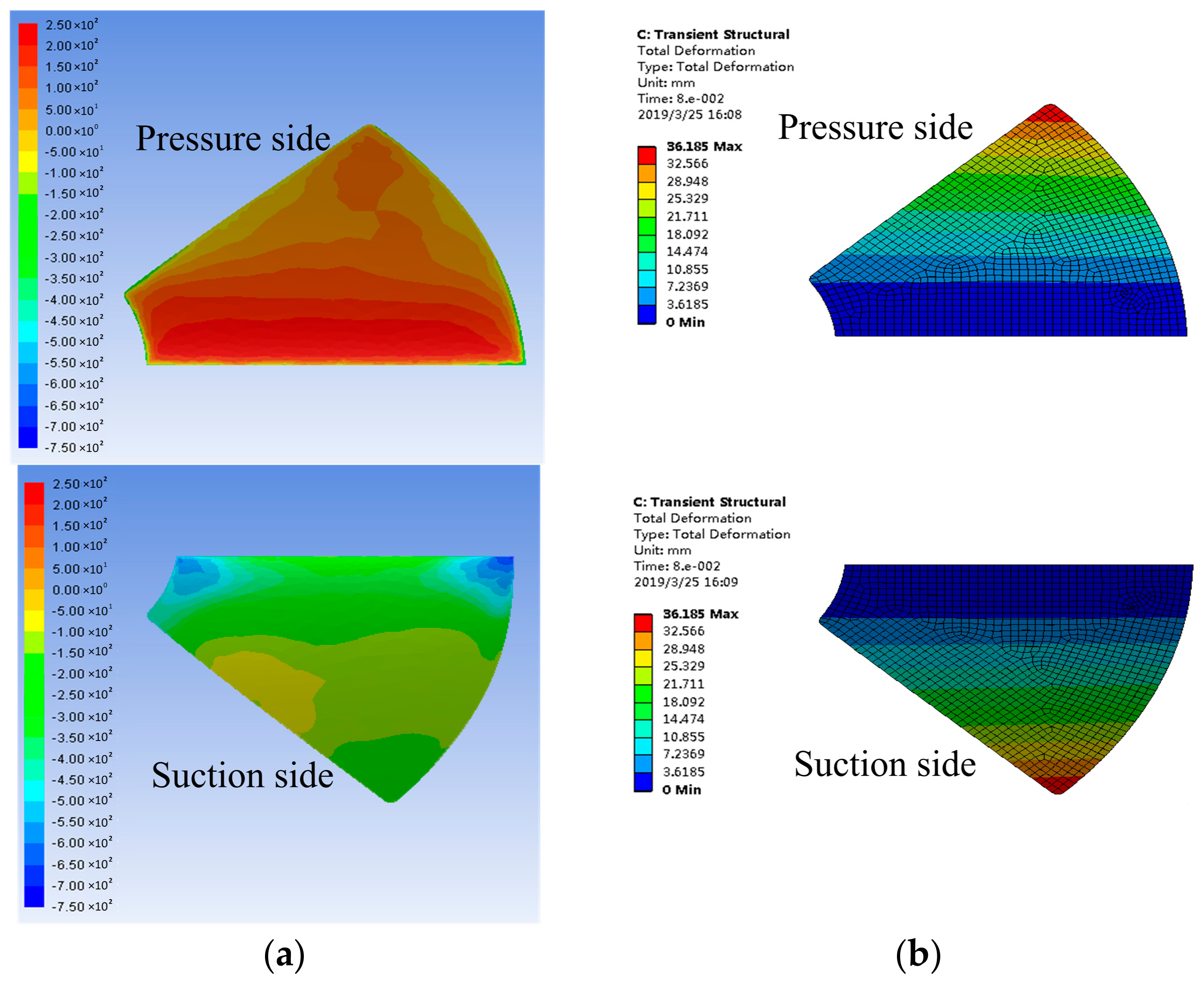
3.6. Analysis Results and Discussions

Based on the two-way fluid-solid coupling analysis of the blade, the pressure and deformation contours on the blade surface were obtained, as shown in Figure 16. The principle of the torque generated by absorber is similar to that of hydraulic turbine. When the absorber is impacted by the water flow, a pressure difference is generated between the pressure side and the suction side, and then the pressure difference forms the torque to the absorber. As can be seen from Figure 16a, the pressure on the pressure side of the blade is mainly positive, and the pressure on the suction side is mainly negative. The pressure difference on the blade surface decreases gradually along the blade chord direction and tends to zero at the trailing edge. The high pressure difference region of the blade mainly concentrates on the leading edge of the blade, that is, the area near the blade connecting rod. From Figure 16b, it can be seen that the deformations of the blade gradually increase along the chord direction, and the deformations of the leading edge portion of the blade are the smallest. Therefore, increasing the deformation degree of the high pressure difference region is an effective way to increase the torque of the absorber.
Through the numerical simulation of flexible blades with different thickness, the torque of the flexible blades to the rotating shaft can be obtained. Then the output torque and hydraulic efficiency of the double-layer absorber can be obtained by Equations (27) and (28), as shown in Figure 17. The analysis results show that the power and efficiency of the absorber increase first and then decrease with the increase of blade thickness. The 65Mn elastic steel blade with thickness of 0.10 mm has the best performance characteristics, and its output mechanical power is 12.8 W, and the hydraulic efficiency is 36.6%.
Based on the current research basis and laboratory calculation conditions, we only performed numerical simulation of two-way fluid-solid coupling for a single blade at a constant speed. This simulation method does not reflect well the interaction between the upper and lower absorbers, the reciprocating water flow impact on the flexible blade and the corresponding transient deformation of the blade. In order to accurately obtain the performance of the entire flexible blade WEC in the impacting water flow and verify the rationality of the above numerical simulation, the experiments with test pool and wave tank were carried out as described below.

4. Experimental Results and Discussions

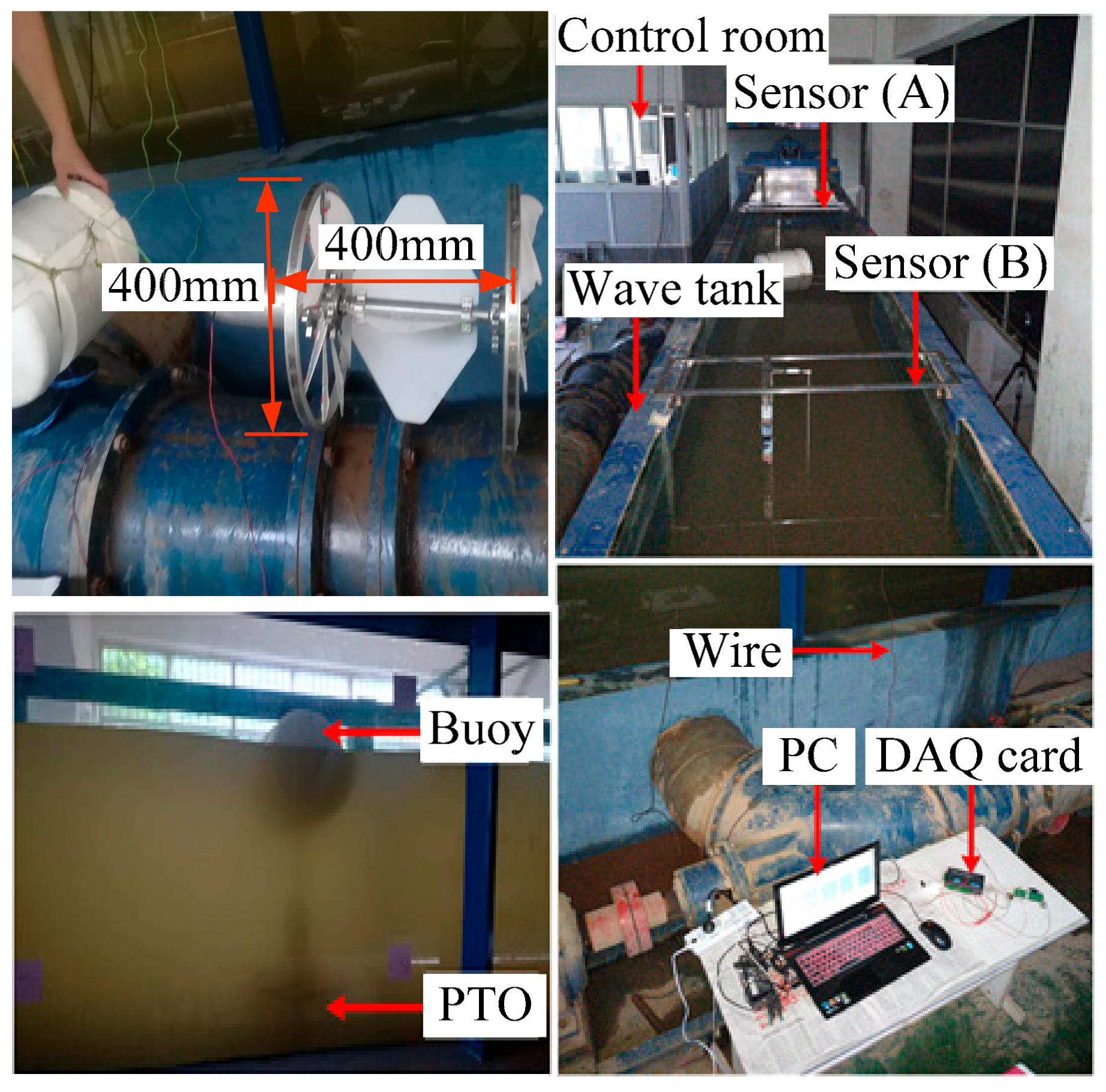
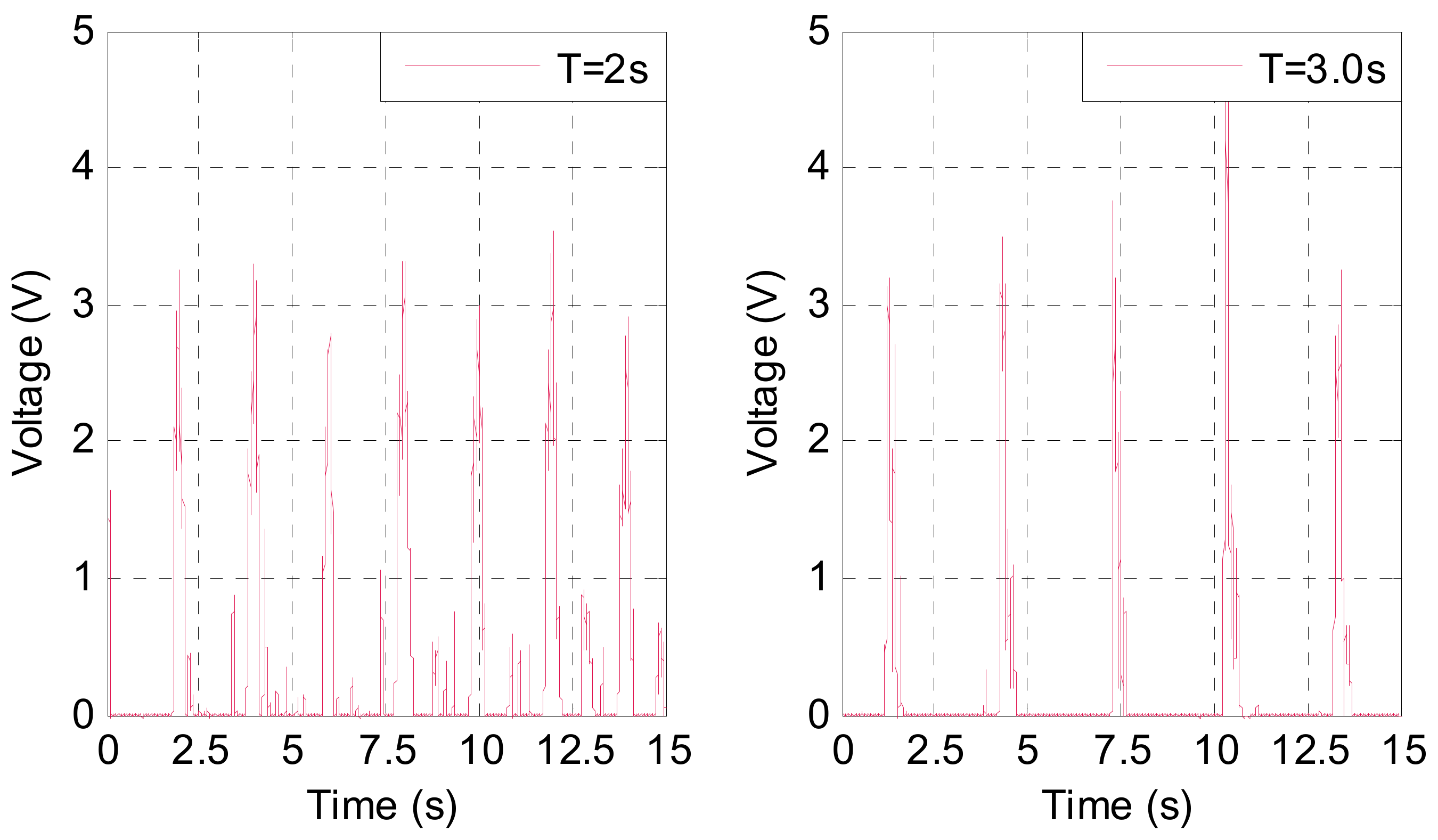
4.1. Experiments in Wave Tank

In order to verify the working principle of the new WEC and preliminarily test its performance characteristics at the beginning of the study, we conducted a wave tank experiment on the physical prototype of WEC [48]. As shown in Figure 18, the test platform mainly includes a wave generator, a water tank, a control room, a data acquisition card (DAQ card), a test computer and other necessary circuit components. The height of the water tank is 1.0 m, the width is 0.8 m, and the length is 22.5 m. In order to simulate the hydrostatic layer in the real sea and avoid possible collisions between the prototype and the bottom of the water tank during the experiments, a square-shaped pit with a side length of 0.8 m was excavated at the bottom of the tank at 6.0 m from the wave generator. The computer’s test program used the LabVIEW language to collect voltage data from the DAQ card and calculated the power and efficiency of the prototype.
A standard spectrum was used in the wave tank experiments, with a water depth of 0.6 m (excluding the depth of the pit) and a wave height of 0.3 m. The output voltage curve of the prototype is shown in Figure 19. The results show that the WEC can output electrical energy stably, and the peak value of voltage has a significant correspondence with the wave period. The wave tank experiments effectively verify the rationality of the working principle and structure design of the new WEC.
Two sets of wave motion periods, sets groups of wave heights, and two sets of additional weight ball masses were set up in the wave tank experiments. The power and efficiency curves of the prototype under the above experiment conditions are shown in Figure 20. The power and efficiency of the WEC increase obviously with the increase of wave height, and the prototype with larger weight has better performance characteristics. Under the current experiment conditions, the prototype with a wave height of 0.3 m, a wave period of 2.0 s, and an additional weight ball mass of 20.11 kg has the best performance. The optimal power is 5.9W and the efficiency is 11.9%.

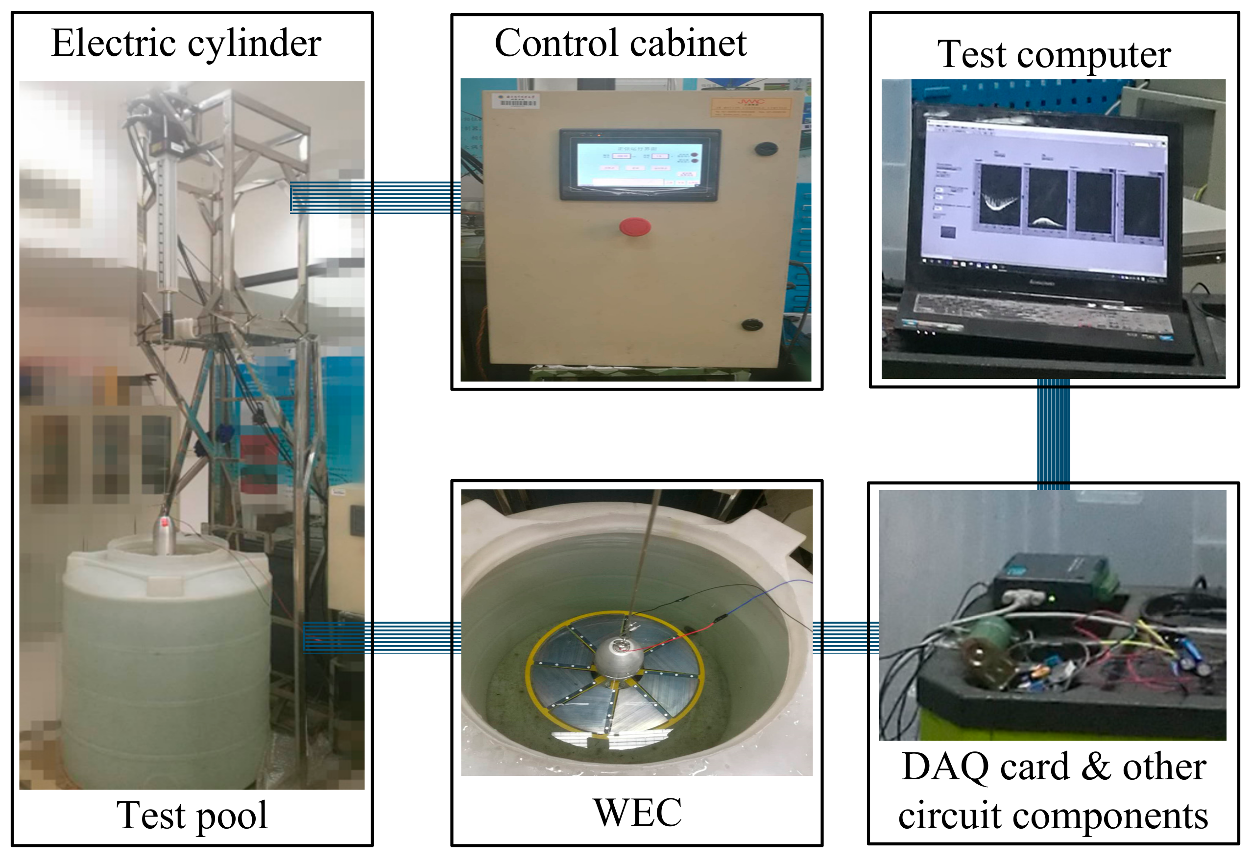
4.2. Experiments in Test Pool

In order to facilitate a large number of quantitative analysis of the system parameters of the WEC prototype at the beginning of the study, we have developed a test platform that can be used under laboratory conditions. The test platform mainly includes a test pool, a linear electric cylinder providing heaving motion, an electric cylinder controller, a computer running test system, a DAQ card, and other necessary circuit components, as shown in Figure 21. In general, when the ratio of channel diameter to device size is greater than 1.35, the side-wall effect is considered to be small [49,50]. The diameter of the test pool is 0.80 m, and the diameter of the absorber is 0.40 m, so the ratio of the two dimensions is 2.00. It can be considered that the side-wall effect of the test pool has less influence on the experiments [49].
The first and second generation counter-rotating self-adaptable WEC developed by our research group is shown in Figure 2. Due to the difference in blade structure and sea conditions of the above two WECs, two sets of power curves with similar time average power were selected for comparison. Figure 22a is a comparison diagram of power curves obtained from the rigid blade WEC and the flexible blade WEC under the heaving motion with an amplitude of 0.2 m and a period of 2 s. The average power of the rigid blade WEC and the flexible blade WEC are 2.46 W and 2.54 W respectively, so the power values are close to each other. The typical peak power of the rigid blade WEC is 8.27 W, while that of the flexible blade WEC is only 3.54 W. That is, the peak power of the rigid blade WEC is 2.34 times that of the flexible blade WEC. Therefore, in the case where the average power of the above two WEC are similar, the power curve of the flexible blade WEC is much smoother and has no sharp power peak.
In order to comprehensively analyze the advantage of the flexible blade WEC in the smoothing power curve compared to the rigid blade WEC, we draw a comparative diagram the ratio of the peak power to the average power as a function of the oscillation period, as shown in Figure 22b. It can be seen that in all periods, the power fluctuation of flexible blade WEC is smaller than that of rigid blade WEC; and the power fluctuation increases with the increase of period. The smooth output power makes the absorber subject to less fluctuation in load torque, which is beneficial to the stability of WEC operation. In addition, the stable output power is also conducive to the efficient use and storage of electrical energy.
To verify the accuracy of the numerical simulation method and results in Section 3.5 and Section 3.6, a comparative experiment was conducted on the small WEC using the motion parameters in Section 3.5. Because we adopted the peak velocity in heaving motion to conduct numerical simulation, the typical peak power of the output power obtained in the experiment was used to compare with the output mechanical power obtained in the numerical simulation. As shown in Figure 23, the peak power curve with blade thickness obtained in the experiments is in good agreement with that obtained in the simulations, but the data ranges of the two are quite different. This is mainly because the power value obtained in the experiments is the secondary conversion of output mechanical energy of the double-layer absorber. Due to the power generation efficiency of the generator and its efficiency fluctuations at different rotational speeds, there are inevitably different degrees of energy loss. The high coincidence of the two output power curves proves that the numerical simulation method for analyzing the performance of the flexible blade is feasible and accurate.
The small WEC is expected to be embedded in low-power unmanned marine equipment as power supply module, and its output power is greatly affected by the load of the back-end circuit. Resistance is an important parameter of the circuit because it is necessary to study its influence on the power generation of the WEC. Figure 24 is a graph showing the variation of the power of WEC with the resistance value. The output power of WEC increases first and then decreases slowly with the increase of resistance. When the resistance is 35 Ω, the peak power and average power of WEC are the largest. Therefore, it can be determined that in the current laboratory environment, the optimum resistance value is 35 Ω. The effect of resistance on WEC power is also affected by multiple factors certainly. In order to simplify the research, we set the resistance of the circuit to 35 Ω in subsequent experiments.
In order to study the influence of the structural parameters and the external sea conditions on the performance characteristics of the WEC, the blade thickness and motion period were selected as the typical variables to conduct the experiments. Figure 25 is a surface diagram showing the combined effect of blade thickness and motion period on the power characteristics of the. The peak power decreases with the increase of the motion period. The peak power increases first and then decreases with the increase of the blade thickness. The peak power of the WEC of 0.10 mm blade thickness is the largest under most wave motion periods. The combined effect of blade thickness and motion period on the average power of the WEC is similar to that of the peak power. However, the high-value region of the average power is smaller than that of the peak power, or the combined effect of the blade thickness and the motion period on the average power is more obvious than that of the peak power. Under the existing laboratory conditions, the power characteristics of the flexible blade WEC are optimal when the blade thickness is 0.10 mm and the motion period is 1.5 s. The best performance characteristics are peak power of 5.8 W and average power of 3.2 W.

5. Conclusions

This paper proposes a new type of small-scale flexible blade WEC, which is based on the self-adaptable counter-rotating operation mechanism. The small WEC is expected to be used as a power supply module for low-power unmanned marine equipment to solve the research bottleneck of the lack of efficient and reliable energy supply methods. Through a comprehensive and systematic study of the performance characteristics of the WEC, the following conclusions are drawn:
(1)
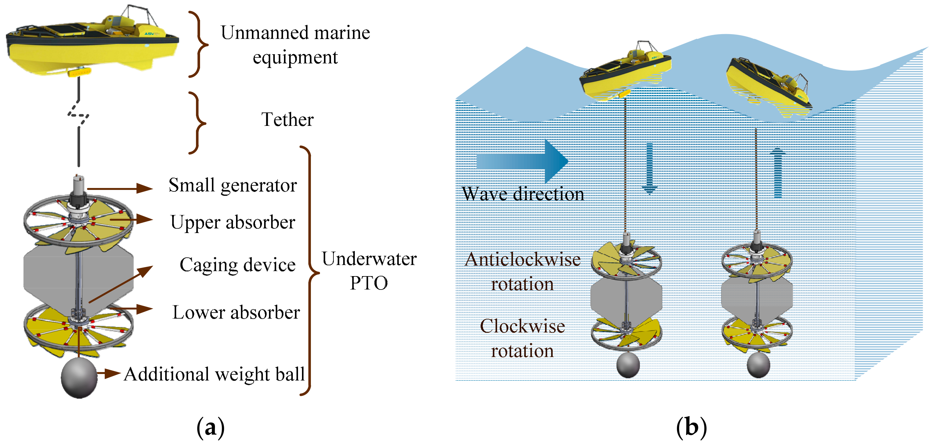
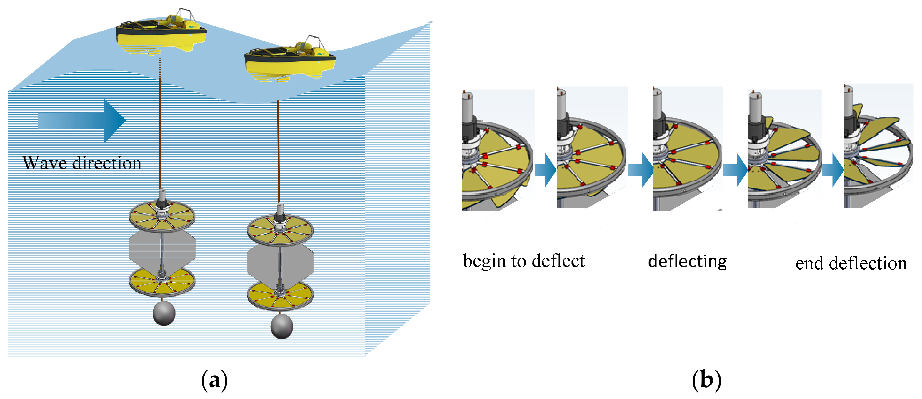
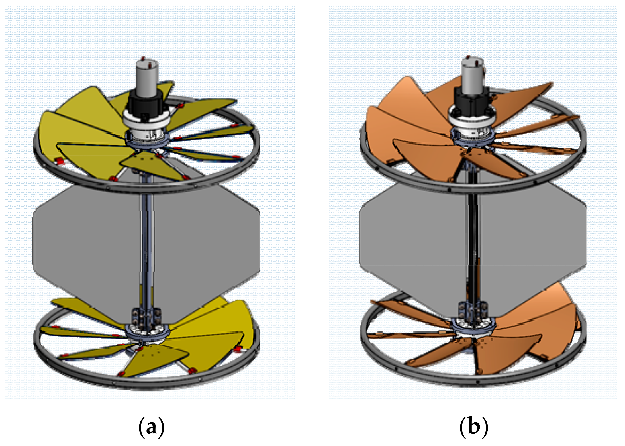
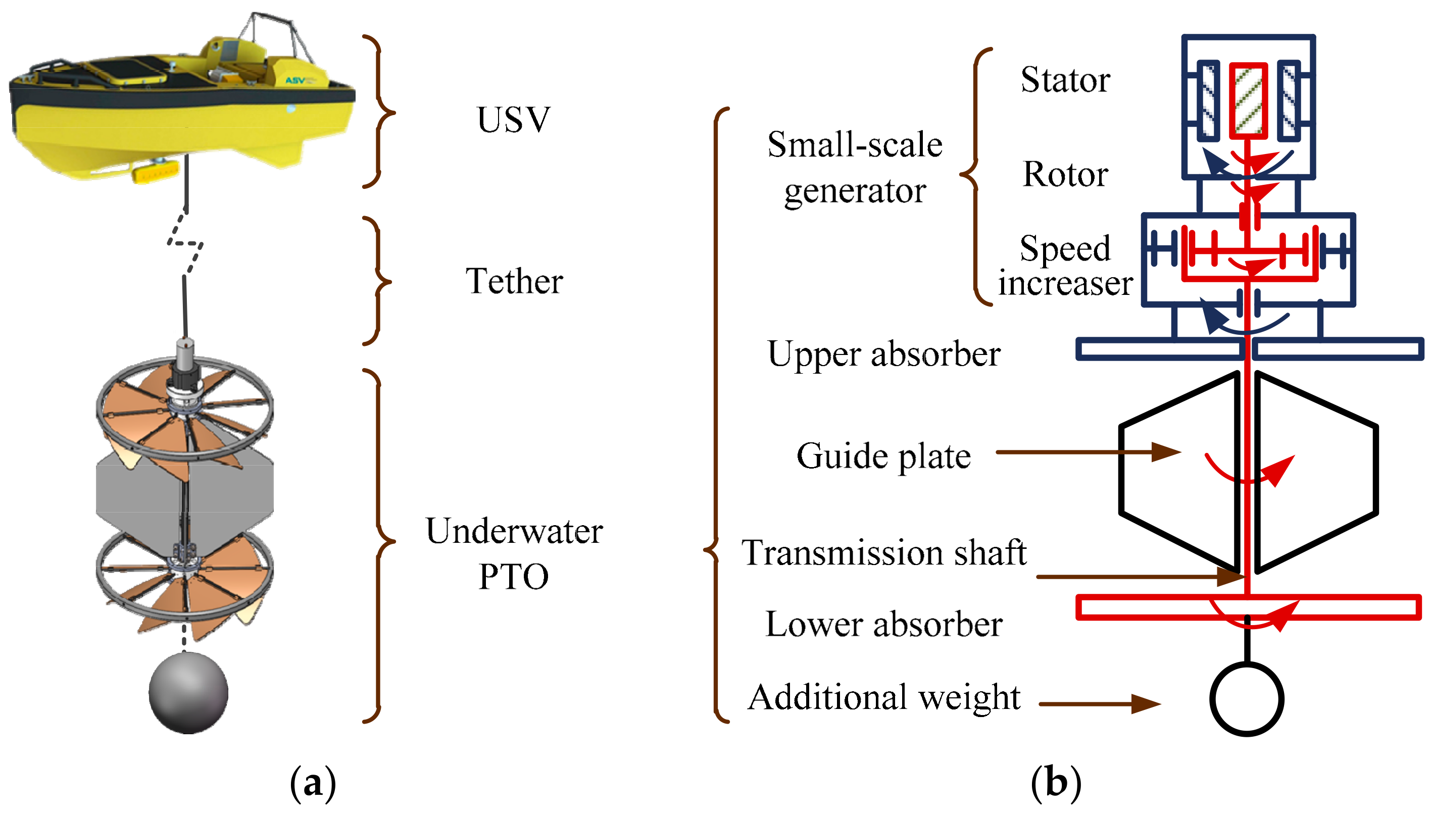
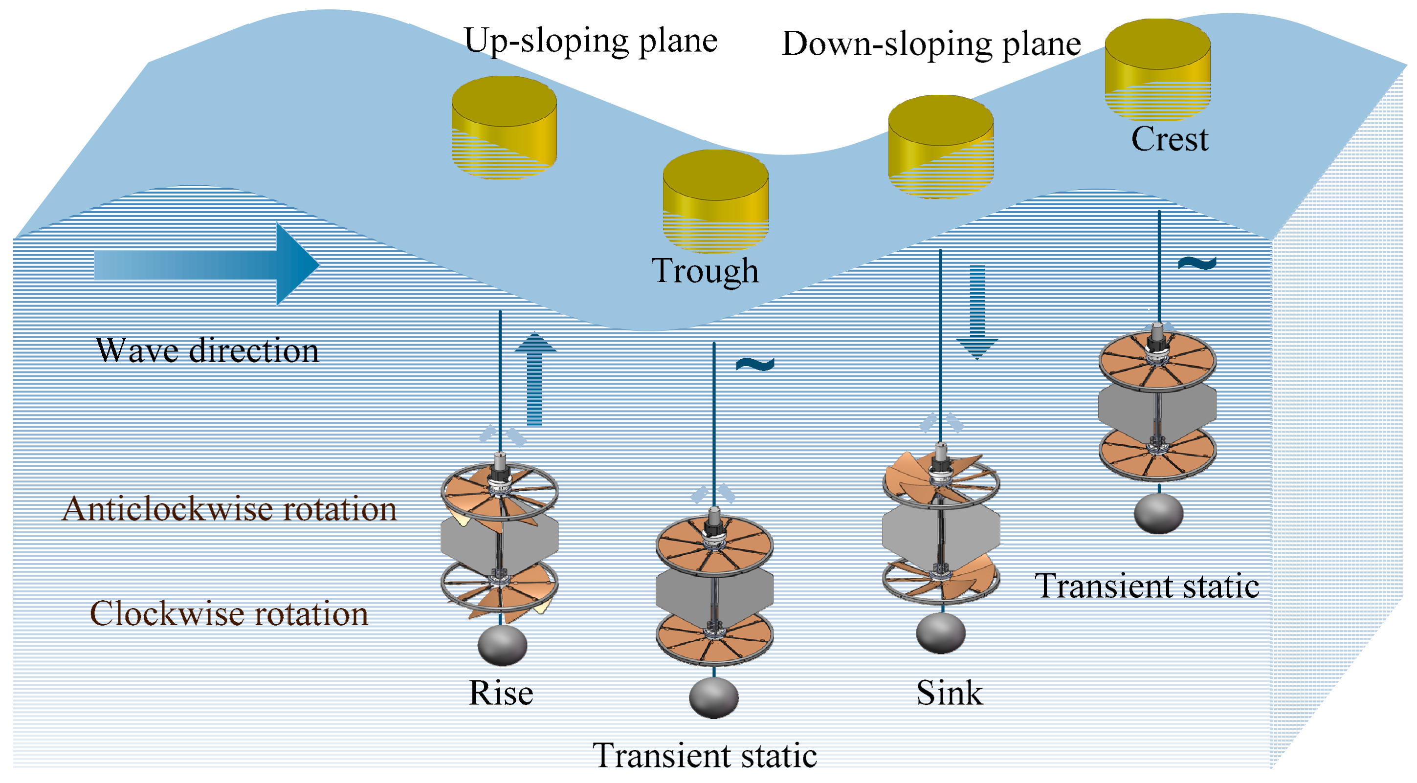
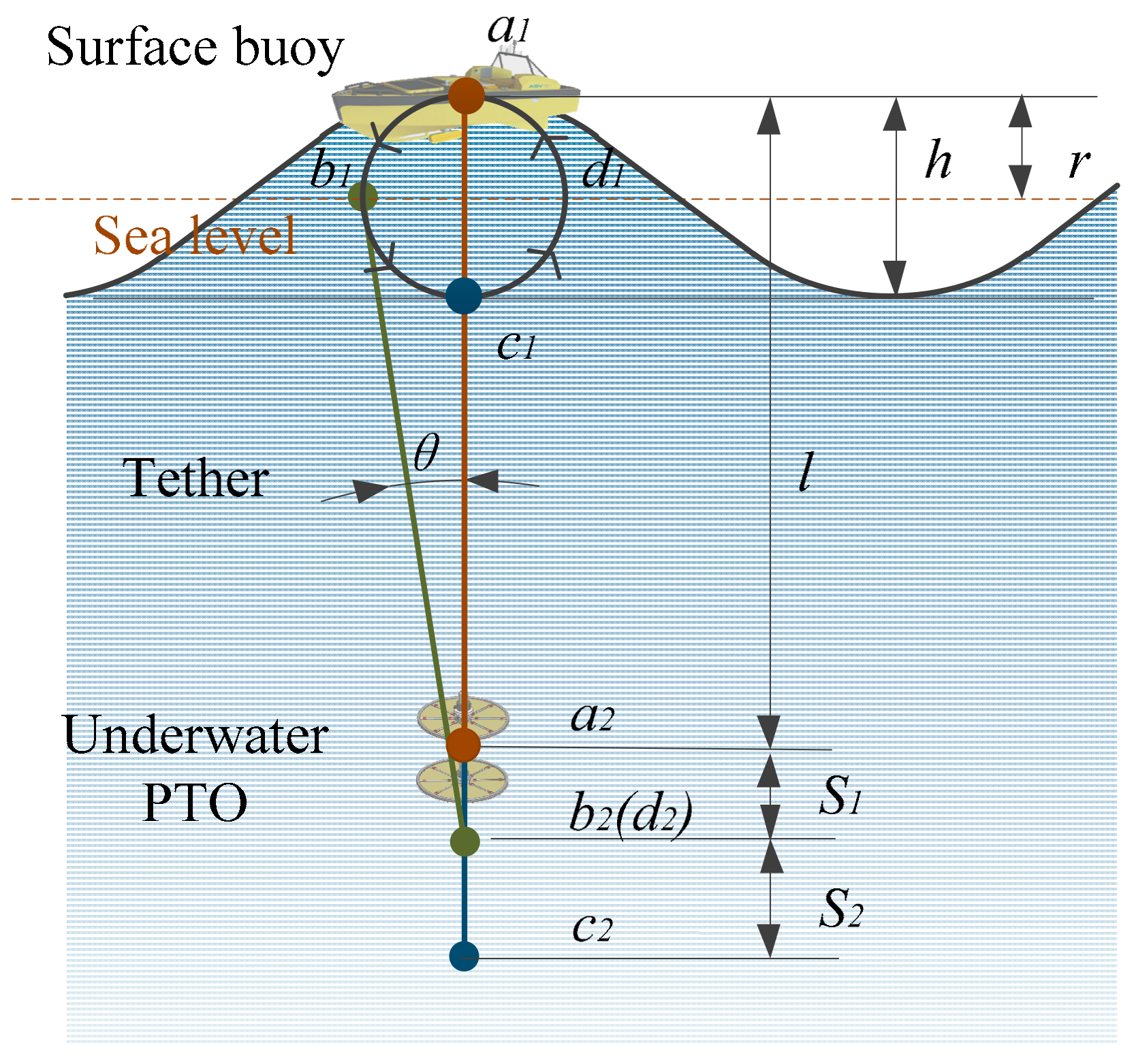
The working principle of the small flexible blade WEC is feasible. The change in the deflection direction of the absorber blade is achieved by self-adaptable bending deformation of the flexible blade itself, which provides the required persistent torque for the unidirectional rotating motion of the single-layer absorber. The design of double-layer absorber balances the overall torque of underwater PTO well and provides the counter-rotating motion required for power generation.
(2)
The theoretical analysis results of the dynamic characteristics of the absorber and its flexible blades clarifies the influence of the structural parameters, operating parameters and the force acting on the blade surface on the performance characteristics of the WEC. This also provides a calculation basis for the data processing in the subsequent numerical simulations and verification experiments.
(3)
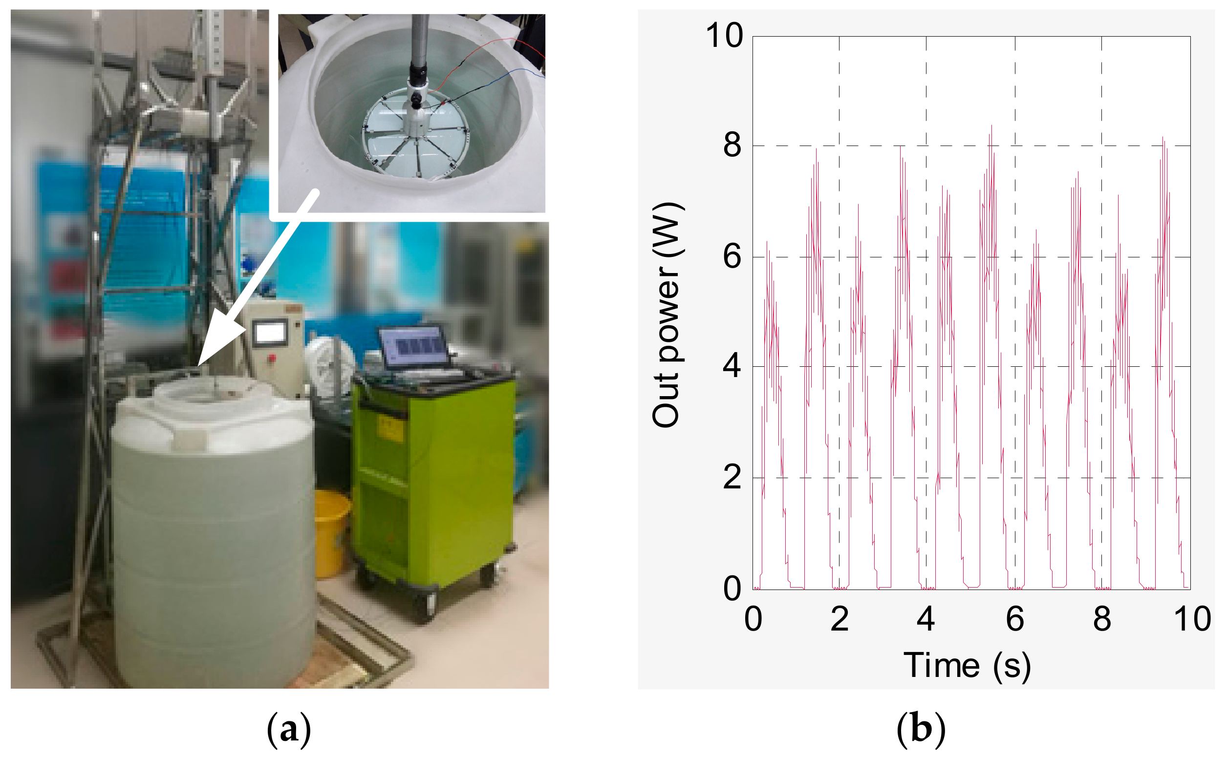
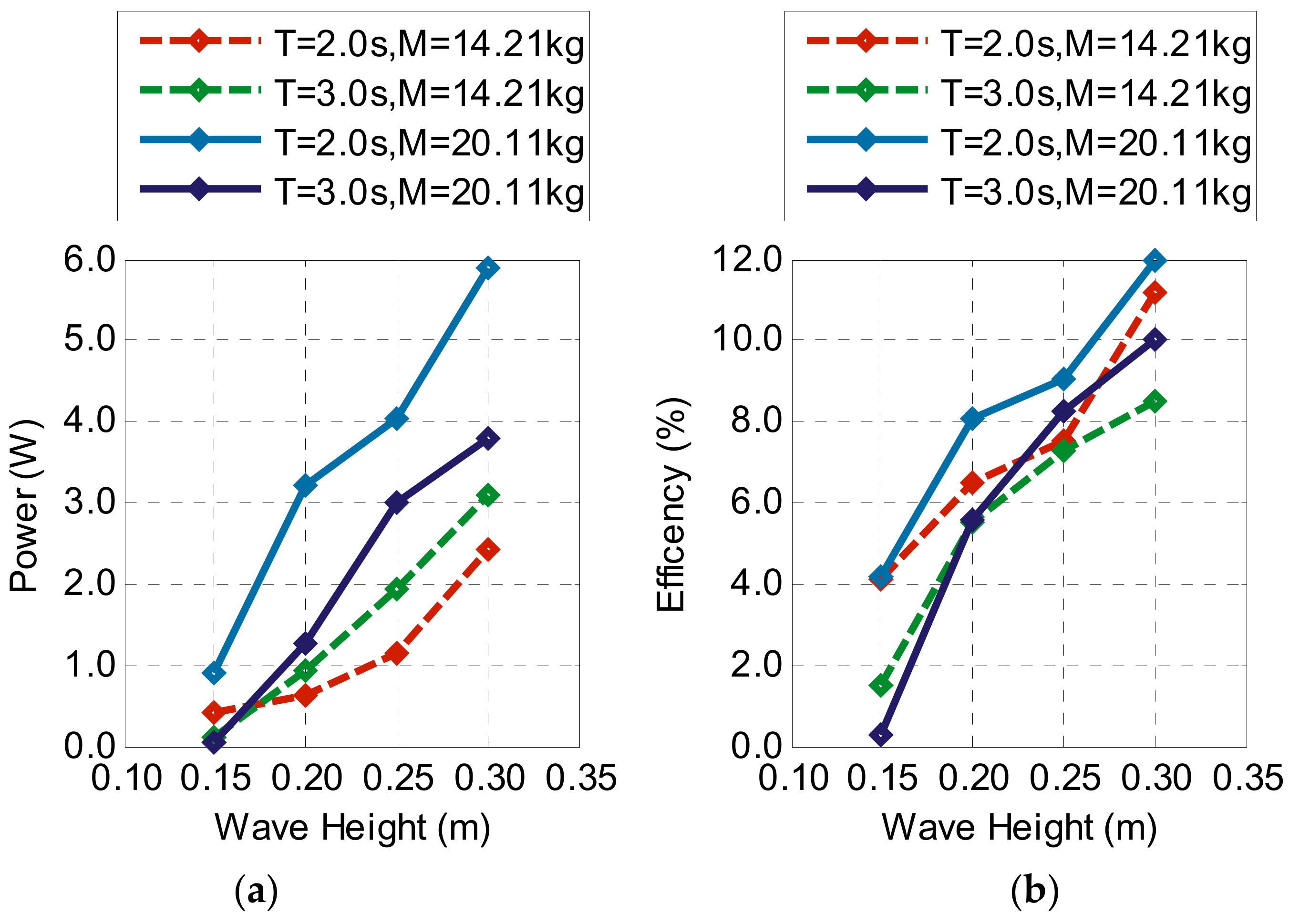
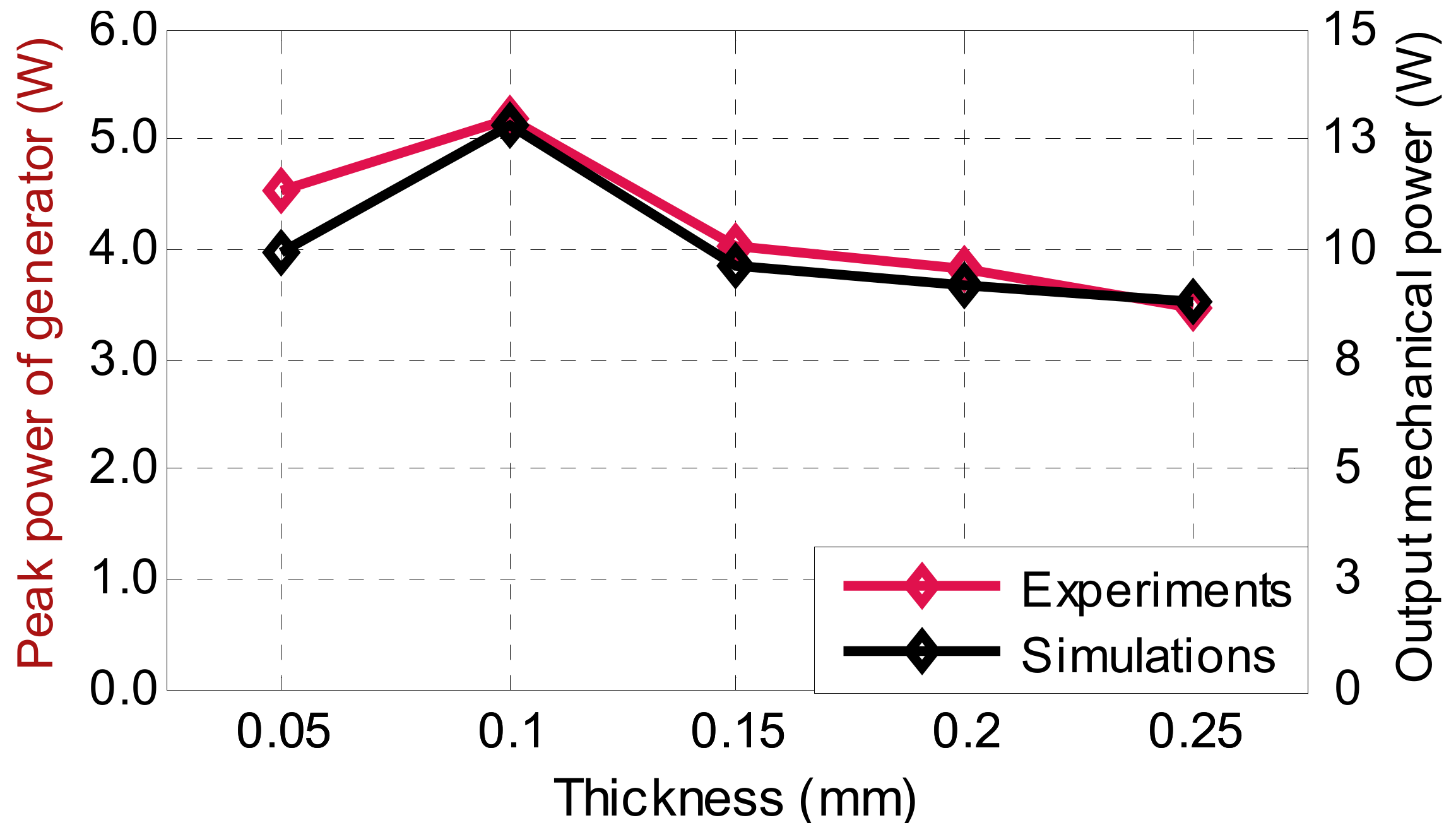
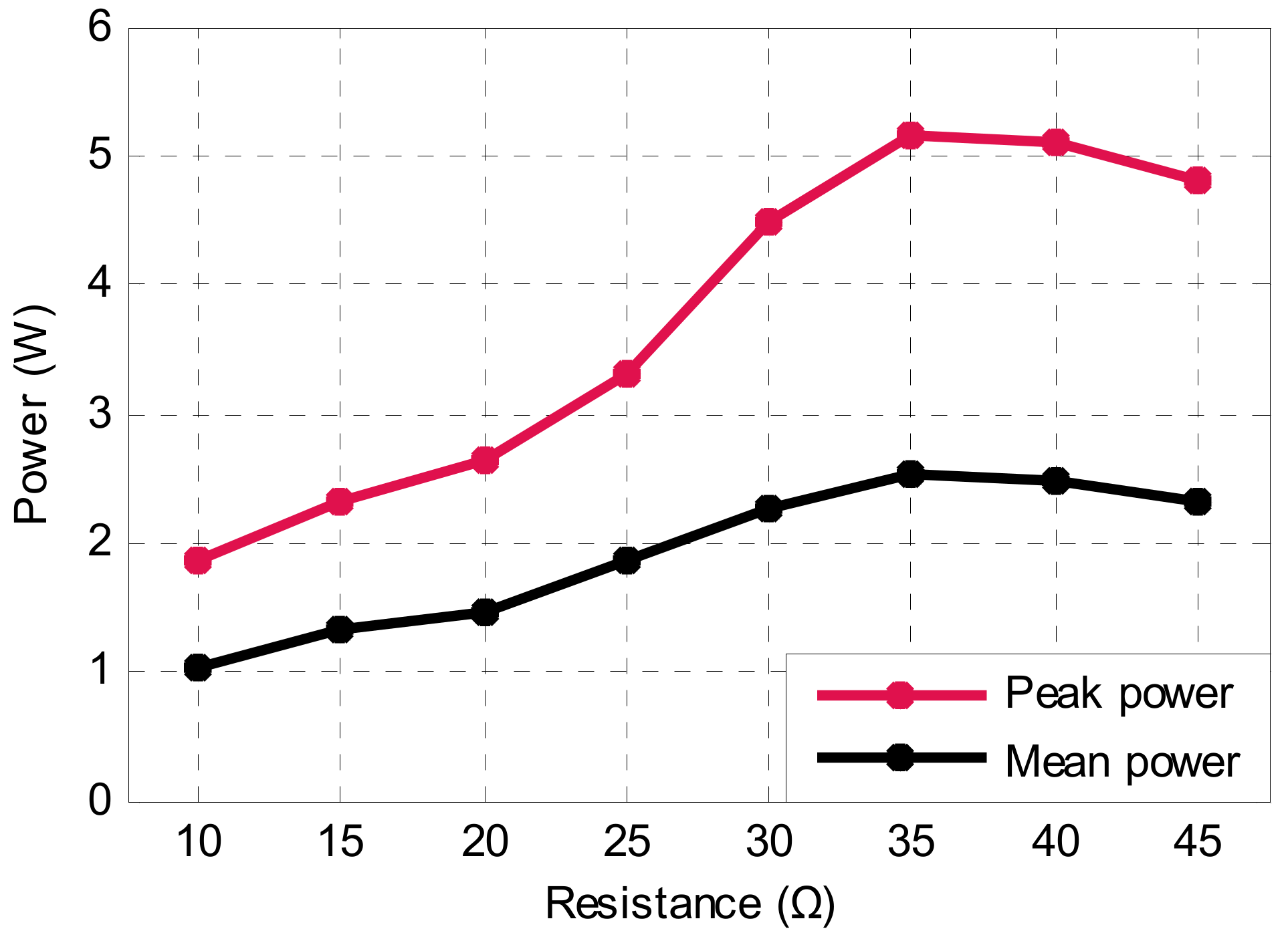
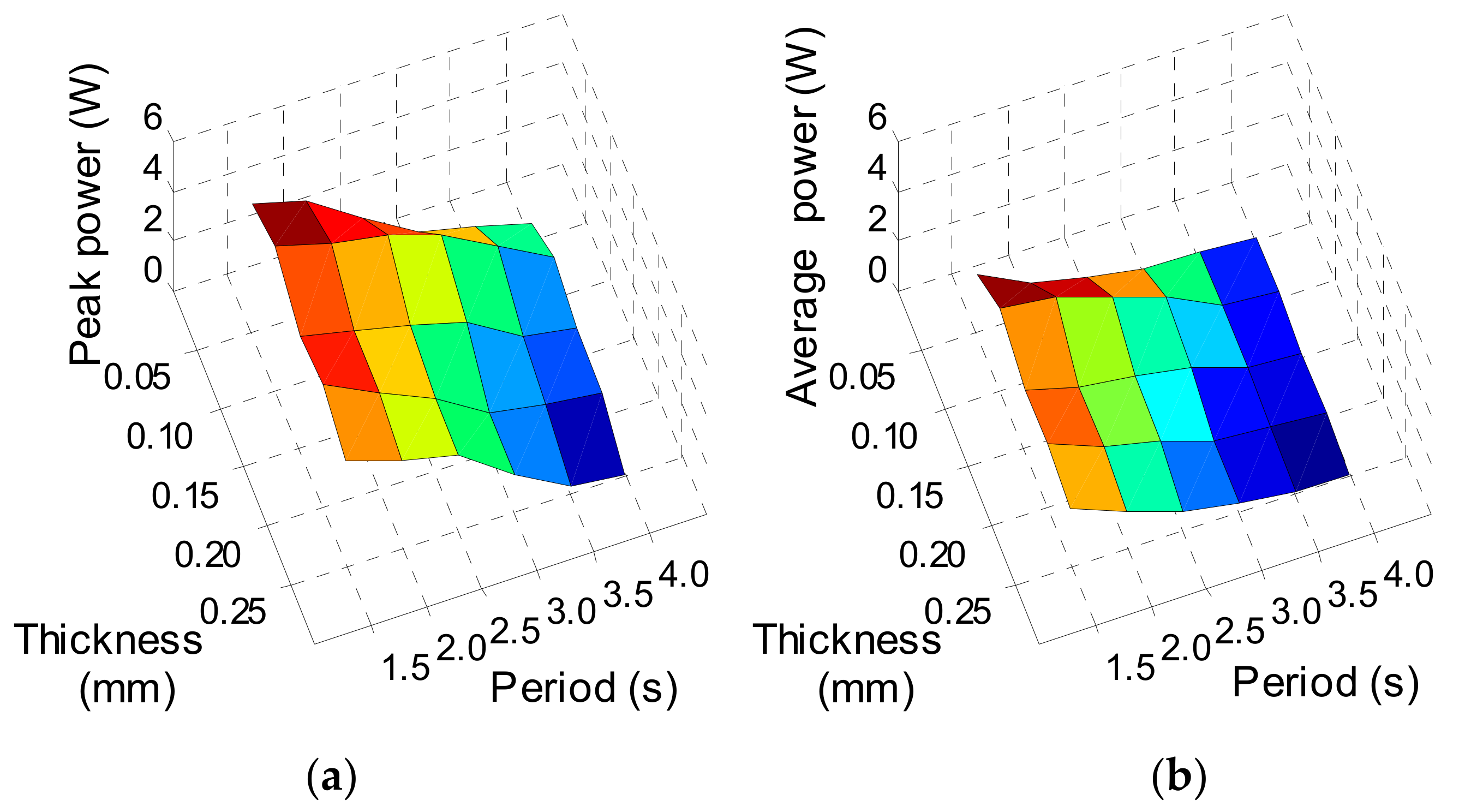
The simulation and experiment results under laboratory conditions show that the mechanical power of the small WEC can reach 12.8 W and the hydraulic efficiency is 36.3%; the peak power of electricity generation is 5.8 W, and the average power is 3.2 W. In most heaving motion periods, the WEC with 65Mn flexible blades achieves the best performance characteristics when the blade thickness is 0.10 mm.
(4)
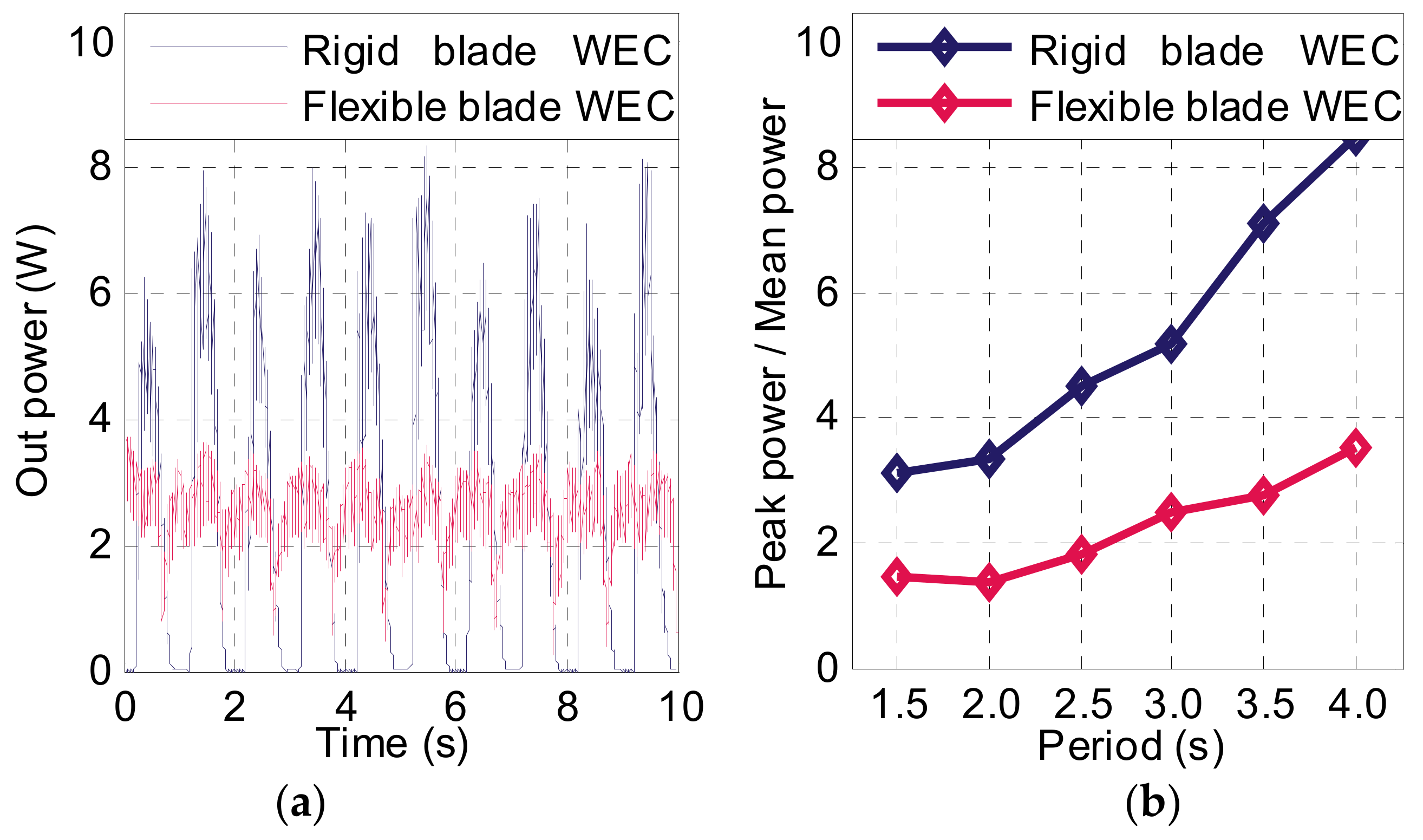
The study results in this paper show that the new generation of flexible blade WEC effectively overcomes the performance disadvantage of the excessive fluctuation of the previous generation of rigid blade WEC. The smooth power output curve facilitates the high-efficient utilization and storage of electric energy, and also makes the load torque fluctuation of the WEC smaller. This is conducive to smooth the operation of WEC and improve the self-adaptable power generation capability of the WEC under low sea states.
The novel small-size WEC has a relatively simple energy conversion process based on the self-adaptable counter-rotating operation mechanism. It can generate electricity steadily and continuously without mooring system and damper plate. The above characteristics of the WEC make it easy for modular assembly, and are not limited by the magnitude of heave motion. It is expected to be used as a power supply module for low power marine equipment and has the potential to develop into a small versatile mobile power supply system. The small WEC has not been tested in the sea, and the reliability and sealing of its mechanical components are yet to be verified. We will conduct sea trials in subsequent studies to speed up the practical process of the novel small-size WEC.

Author Contributions

Conceptualization, C.S., J.S. and Z.L. (Zirong Luo); Data curation, G.W.; Formal analysis, C.S.; Funding acquisition, Z.L. (Zirong Luo); Investigation, C.S. and Z.L. (Zhongyue Lu); Methodology, J.S. and Y.Z.; Software, C.S. and G.W.; Validation, Z.L. (Zhongyue Lu); Visualization, C.S.; Writing—original draft, C.S.; Writing—review & editing, Y.Z.

Funding

This research was funded by the National Natural Science Foundation of China, grant number 51,475,465; the Hunan Provincial Innovation Foundation for Postgraduate, grant number CX2015B014.

Acknowledgments

In this section you can acknowledge any support given which is not covered by the author contribution or funding sections. This may include administrative and technical support, or donations in kind (e.g., materials used for experiments).

Conflicts of Interest

The authors declare no conflict of interest.

References

  1. Incer, I. Renewable energy and sustainable development: A crucial review. Renew. Sustain. Energy Rev. 2000, 4, 157–175. [Google Scholar] [CrossRef]
  2. Etersen, S.; Krätschell, A.; Augustin, N.; Jamieson, J.; Hein, J.R.; Hannington, M.D. News from the seabed–Geological characteristics and resource potential of deep-sea mineral resources. Mar. Policy 2016, 70, 175–187. [Google Scholar] [CrossRef]
  3. Neill, S.P.; Vögler, A.; Goward-Brown, A.J.; Baston, S.; Lewis, M.J.; Gillibrand, P.A.; Waldman, S.; Woolf, D.K. The wave and tidal resource of Scotland. Renew. Energy 2017, 114, 3–17. [Google Scholar] [CrossRef]
  4. Ildow, J.T.; Mcilgorm, A. The importance of estimating the contribution of the oceans to national economies. Mar. Policy 2010, 34, 367–374. [Google Scholar]
  5. Lindemuth, M.; Murphy, R.; Steimle, E.; Armitage, W.; Dreger, K.; Elliot, T.; Hall, M.; Kalyadin, D.; Kramer, J.; Palankar, M. Sea robot-assisted inspection. IEEE Robot. Autom. Mag. 2011, 18, 96–107. [Google Scholar] [CrossRef]
  6. Seto, M.L. (Ed.) Marine Robot Autonomy; Springer Science & Business Media: Berlin, Germany, 2012. [Google Scholar]
  7. Riksen, C.C.; Seaglider, A. Long-Range Autonomous Underwater Vehicle for Oceanographic Research. IEEE J. Ocean. Eng. 2001, 26, 424–436. [Google Scholar] [CrossRef]
  8. Ang, X.; Shang, J.; Luo, Z.; Tang, L.; Zhang, X.; Li, J. Reviews of power systems and environmental energy conversion for unmanned underwater vehicles. Renew. Sustain. Energy Rev. 2012, 16, 1958–1970. [Google Scholar]
  9. Insey, J.C.; Eustice, R.M.; Whitcomb, L.L. A survey of underwater vehicle navigation: Recent advances and new challenges. In Proceedings of the IFAC Conference of Manoeuvering and Control of Marine Craft, Lisbon, Portugal, 20–22 September 2006; Volume 88, pp. 1–12. [Google Scholar]
  10. Enderson, E.; Pantelakis, T.; An, E. Energy systems for FAU AUVs [autonomous underwater vehicles]. In Proceedings of the 2002 Workshop on Autonomous Underwater Vehicles, San Antonio, TX, USA, 21–21 June 2002; pp. 5–10. [Google Scholar]
  11. Ai, Q.; Brett, D.J.L.; Browning, D.; Brandon, N.P. A sizing-design methodology for hybrid fuel cell power systems and its application to an unmanned underwater vehicle. J. Power Sources 2010, 195, 6559–6569. [Google Scholar]
  12. Endez, A.; Leo, T.; Herreros, M. Current state of technology of fuel cell power systems for autonomous underwater vehicles. Energies 2014, 7, 4676–4693. [Google Scholar] [CrossRef]
  13. Alter, S.H. Wave power. Nature 1974, 249, 720–724. [Google Scholar] [CrossRef]
  14. Lément, A.; McCullen, P.; Falcão, A.; Fiorentino, A.; Gardner, F.; Hammarlund, K.; Lemonis, G.; Lewis, T.; Nielsen, K.; Petroncini, S. Wave energy in Europe: Current status and perspectives. Renew. Sustain. Energy Rev. 2002, 6, 405–431. [Google Scholar] [CrossRef]
  15. Egnier, E. Oil and energy price volatility. Energy Econ. 2007, 29, 405–427. [Google Scholar] [CrossRef]
  16. Ntonio, F.O. Wave energy utilization: A review of the technologies. Renew. Sustain. Energy Rev. 2010, 14, 899–918. [Google Scholar]
  17. Rew, B.; Plummer, A.R.; Sahinkaya, M.N. A review of wave energy converter technology. J. Power Energy 2009, 223, 887–902. [Google Scholar] [Green Version]
  18. Alcão, A.F.O.; Henriques, J.C.C. Oscillating-water-column wave energy converters and air turbines: A review. Renew. Energy 2016, 85, 1391–1424. [Google Scholar]
  19. Ópez, I.; Andreu, J.; Ceballos, S.; de Alegría, I.M.; Kortabarria, I. Review of wave energy technologies and the necessary power-equipment. Renew. Sustain. Energy Rev. 2013, 27, 413–434. [Google Scholar]
  20. Iles, L.F. A Permanent-Magnet Linear Generator Wave Energy Converter for Low Power Ocean Sensors. Master’s Thesis, Oregon State University, Corvallis, OR, USA, 27 June 2017. [Google Scholar]
  21. Lean Energy from Ocean Waves-Ongoing Projects. Available online: https://wello.eu (accessed on 24 May 2019).
  22. Racco, G.; Cagninei, A.; Giorcelli, E.; Mattiazzo, G.; Poggi, D.; Raffero, M. Experimental validation of the ISWEC wave to PTO model. Ocean Eng. 2016, 120, 40–51. [Google Scholar]
  23. Ave for Energy Srl R&D DEVELOPMENT. Available online: http://www.waveforenergy.com/tech/iswec (accessed on 24 May 2019).
  24. Power PRODUCT DEVELOPMENT. Available online: https://columbiapwr.com/product-development/ (accessed on 24 May 2019).
  25. U.S. Department of Energy Awards $25 Million for Next-Generation Marine Energy Research Projects. Available online: https://www.energy.gov/articles/us-department-energy-awards-25-million-next-generation-marine-energy-research-projects (accessed on 24 May 2019).
  26. Orbach, A.; Fjetland, K.B.; Hestetun, G.V.; Impelluso, T.J. Gyroscopic Wave Energy Generator for Fish Farms and Rigs. In Proceedings of the ASME 2018 International Mechanical Engineering Congress and Exposition, Pittsburgh, PA, USA, 9–15 November 2018; American Society of Mechanical Engineers: New York, NY, USA, 2018; p. V06BT08A021. [Google Scholar]
  27. Usu, E.; Onea, F. A review of the technologies for wave energy extraction. Clean Energy 2018, 2, 10–19. [Google Scholar] [Green Version]
  28. Ang, L.; Engström, J.; Göteman, M.; Isberg, J. Constrained optimal control of a point absorber wave energy converter with linear generator. J. Renew. Sustain. Energy 2015, 7, 043127. [Google Scholar]
  29. Bdelkhalik, O.; Zou, S. Control of small two-body heaving wave energy converters for ocean measurement applications. Renew. Energy 2019, 132, 587–595. [Google Scholar] [CrossRef]
  30. Roducts of OPT. Available online: https://www.oceanpowertechnologies.com/product (accessed on 20 April 2019).
  31. Einstein, A.; Fredrikson, G.; Parks, M.J.; Nielsen, K. AquaBuOY-the offshore wave energy converter numerical modeling and optimization. In Proceedings of the Oceans’ 04 MTS/IEEE Techno-Ocean’04 (IEEE Cat. No. 04CH37600), Kobe, Japan, 9–12 November 2004; Volume 4, pp. 1854–1859. [Google Scholar]
  32. Un, C.; Luo, Z.; Shang, J.; Lu, Z.; Zhu, Y.; Wu, G. Design and Numerical Analysis of a Novel Counter-Rotating Self-Adaptable Wave Energy Converter Based on CFD Technology. Energies 2018, 11, 694. [Google Scholar] [Green Version]
  33. Ong, D.; Shang, J.; Luo, Z.; Sun, C.; Wu, W. Energy Efficiency Analysis of Multi-Type Floating Bodies for a Novel Heaving Point Absorber with Application to Low-Power Unmanned Ocean Device. Energies 2018, 11, 3282. [Google Scholar] [Green Version]
  34. Ie, O.; Li, B.; Yan, Q. Computational and experimental study on dynamics behavior of a bionic underwater robot with multi-flexible caudal fins. Ind. Robot.-Int. J. Robot. Res. Appl. 2018, 45, 267–274. [Google Scholar]
  35. Olkoff, S.W. Robotics and Power Measurements of the RoboTuna. Ph.D. Thesis, Massachusetts Institute of Technology, Cambridge, MA, USA, 1999. [Google Scholar]
  36. Iorgi, G.; Ringwood, J.V. Computationally efficient nonlinear Froude–Krylov force calculations for heaving axisymmetric wave energy point absorbers. J. Ocean Eng. Mar. Energy 2017, 3, 21–33. [Google Scholar] [CrossRef]
  37. Iorgi, G.; Ringwood, J.V. Analytical formulation of nonlinear froude-krylov forces for surging-heaving-pitching point absorbers. In Proceedings of the ASME 2018 37th International Conference on Ocean, Offshore and Arctic Engineering. American Society of Mechanical Engineers, Madrid, Spain, 17–22 June 2018; p. V010T09A036. [Google Scholar]
  38. Wamp Group. Ocean Wave Modeling; Springer Science & Business Media: Berlin, Germany, 1985. [Google Scholar]
  39. Ang, X.; Song, B.; Wang, P.; Sun, C. Hydrofoil optimization of underwater glider using Free-Form Deformation and surrogate-based optimization. Int. J. Naval Archit. Ocean Eng. 2018, 6, 730–740. [Google Scholar]
  40. Sa, K.; Arshad, M.R.; Ishak, S. A hybrid-driven underwater glider model, hydrodynamics estimation, and an analysis of the motion control. Ocean Eng. 2014, 81, 111–129. [Google Scholar]
  41. Unus, A.C. Fluid Mechanics: Fundamentals and Applications (Si Units); Tata McGraw Hill Education Private Limited: New York, NY, USA, 2010. [Google Scholar]
  42. Ebouillat, S.; Liksonov, D. Fluid–structure interaction in partially filled liquid containers: A comparative review of numerical approaches. Comput. Fluids 2010, 39, 739–746. [Google Scholar] [CrossRef]
  43. Nup, K.C.; Lee, Y.H.; Thapa, B. CFD study on prediction of vortex shedding in draft tube of Francis turbine and vortex control techniques. Renew. Energy 2016, 86, 1406–1421. [Google Scholar]
  44. Einer-Gundersen, D.H. A novel flexible foil vertical axis turbine for river, ocean, and tidal applications. Appl. Energy 2015, 151, 60–66. [Google Scholar] [CrossRef]
  45. Dhikari, R.; Vaz, J.; Wood, D. Cavitation inception in crossflow hydro turbines. Energies 2016, 9, 237. [Google Scholar] [CrossRef]
  46. Atsushima, K.; Murayama, M.; Nakahashi, K. Unstructured dynamic mesh for large movement and deformation. In Proceedings of the 40th AIAA Aerospace Sciences Meeting & Exhibit, Reno, NV, USA, 14–17 January 2002; p. 122. [Google Scholar]
  47. Rawczewicz, M. Micro Ocean Renewable Energy. Available online: http://www.ericgreeneassociates.com/images/Micro_Ocean_Renewable_Energy.pdf (accessed on 20 April 2019).
  48. Wu, G.; Lu, Z.; Luo, Z.; Shang, J.; Sun, C.; Zhu, Y. Experimental Analysis of a Novel Adaptively Counter-Rotating Wave Energy Converter for Powering Drifters. J. Mar. Sci. Eng. 2019, 7, 171. [Google Scholar] [CrossRef]
  49. Atsushita, D.; Okuma, K.; Watanabe, S.; Furukawa, A. Simplified structure of ducted Darrieus-type hydro turbine with narrow intake for extra-low head hydropower utilization. J. Fluid Sci. Technol. 2008, 3, 387–397. [Google Scholar] [CrossRef]
  50. Himokawa, K.; Furukawa, A.; OKuma, K.; Matsushita, D.; Watanabe, S. Side-wall effect of runner casing on performance of Darrieus-type hydro turbine with inlet nozzle for extra-low head utilization. Sci. China Ser. E Technol. Sci. 2010, 53, 93–99. [Google Scholar] [CrossRef]
Figure 1. PowerBuoy PB3: (a) Overall structure; (b) Conversion mechanism. Adapted with permission from Ocean Power Technologies, 2019.
Jmse 07 00223 g001
Figure 2. Physical prototype of the novel WEC: (a) Rigid blade WEC; (b) Flexible blade WEC.
Jmse 07 00223 g002
Figure 3. Rigid blade WEC: (a) Conceptual design; (b) Working process.
Jmse 07 00223 g003
Figure 4. Experiments of rigid blade WEC: (a) Experiments; (b) Output power curve.
Jmse 07 00223 g004
Figure 5. Blade commutation process of rigid blade WEC: (a) Crest and trough position; (b) Blade deflection.
Jmse 07 00223 g005
Figure 6. Comparison of conceptual design of the two WEC: (a) Rigid blade WEC; (b) Flexible blade WEC.
Jmse 07 00223 g006
Figure 7. Mechanical structure: (a) Conceptual design; (b) Transmission sketch.
Jmse 07 00223 g007
Figure 8. Working process of flexible blade WEC.
Jmse 07 00223 g008
Figure 9. Energy conversion flow chart.
Jmse 07 00223 g009
Figure 10. Interaction between multi-type surface buoys and wave motions: (a) wave force; (b) wave energy extraction efficiency.
Jmse 07 00223 g010
Figure 11. Schematic diagram of the relationship between wave motion and WEC [32]. Adapted from [32], with permission from MDPI, 2019.
Jmse 07 00223 g011
Figure 12. Kinematic characteristics of single-layer absorber and its blades.
Jmse 07 00223 g012
Figure 13. Relative impacting water flow and angle of attack of the blade.
Jmse 07 00223 g013
Figure 14. Dynamic characteristics of blade.
Jmse 07 00223 g014
Figure 15. Decomposition of blade forces.
Jmse 07 00223 g015
Figure 16. Analysis results of numerical simulation of flexible blades: (a) Pressure contours; (b) Deformation contours.
Jmse 07 00223 g016
Figure 17. Numerical simulation results of double-layer absorber: (a) Output mechanical power; (b) Hydraulic efficiency.
Jmse 07 00223 g017
Figure 18. Wave tank test platform.
Jmse 07 00223 g018
Figure 19. Output voltage curve of the prototype.
Jmse 07 00223 g019
Figure 20. Power and efficiency curves of the prototype in the in-wave tank experiments: (a) power curve; (b) efficiency curve.
Jmse 07 00223 g020
Figure 21. Test Pool test platform.
Jmse 07 00223 g021
Figure 22. Comparison of rigid blade WEC and flexible blade WEC: (a) Instantaneous power curves; (b) Power fluctuations.
Jmse 07 00223 g022
Figure 23. Comparison of power obtained in experiments and numerical simulations.
Jmse 07 00223 g023
Figure 24. Effect of resistance on WEC power generation.
Jmse 07 00223 g024
Figure 25. The combined effect of motion period and blade thickness on WEC power characteristics: (a) Peak power; (b) Average power.
Jmse 07 00223 g025

