Article

Numerical Study on the Natural Convection of Air in a Cubic Cavity Subjected to a Yawing Motion

1
School of Design, Shanghai Jiao Tong University, Shanghai 200240, China
2
Merchant Marine College, Shanghai Maritime University, Shanghai 201306, China
*
Author to whom correspondence should be addressed.
J. Mar. Sci. Eng. 2019, 7(7), 204; https://doi.org/10.3390/jmse7070204
Submission received: 27 May 2019 / Revised: 27 June 2019 / Accepted: 27 June 2019 / Published: 1 July 2019

Abstract

:
Natural convections subjected to multi-Degree of Freedom (DoF) motion are much more complex than those in static case, and those subjected to yawing motion are the simplest and ideal case for investigating their characteristics due to less interactive parameters. In this paper, the characteristic of natural convection under yawing motion was studied systematically to clarify the interaction between yawing motion and thermal-dynamic behavior. First of all, the mathematical model was established in a non-inertial coordinate system, and the dimensionless governing equations were derived. Subsequently, the governing equations were discretized in the framework of the finite volume method, and a computer code was developed and validated. After that, the natural convection under yawing motion was calculated with different combinations of dimensionless parameters, and the influence of rotation frequency and amplitude on heat and mass transfer was investigated. It was found that the yawing motion plays a notable role in flow and heat transfer, depending on the relative magnitudes of rotation-induced velocity and buoyancy-induced velocity: At a lower Rayleigh number of 104, the Nusselt number on hot boundary is enhanced by approximately 25% when the rotation period is changed from 12 s to 2 s; while the changing in rotation period from 12 s to 2 s did not induce obvious difference in hot-boundary Nusselt number for a higher Rayleigh number of 105. It is concluded that the vertical-axis harmonic rotation enhances heat transfer if the rotation-induced velocity dominates the flow. The clarification of natural convection characteristic in yawing motion provides convenience for analyzing that in other multi-DoF systems.

1. Introduction

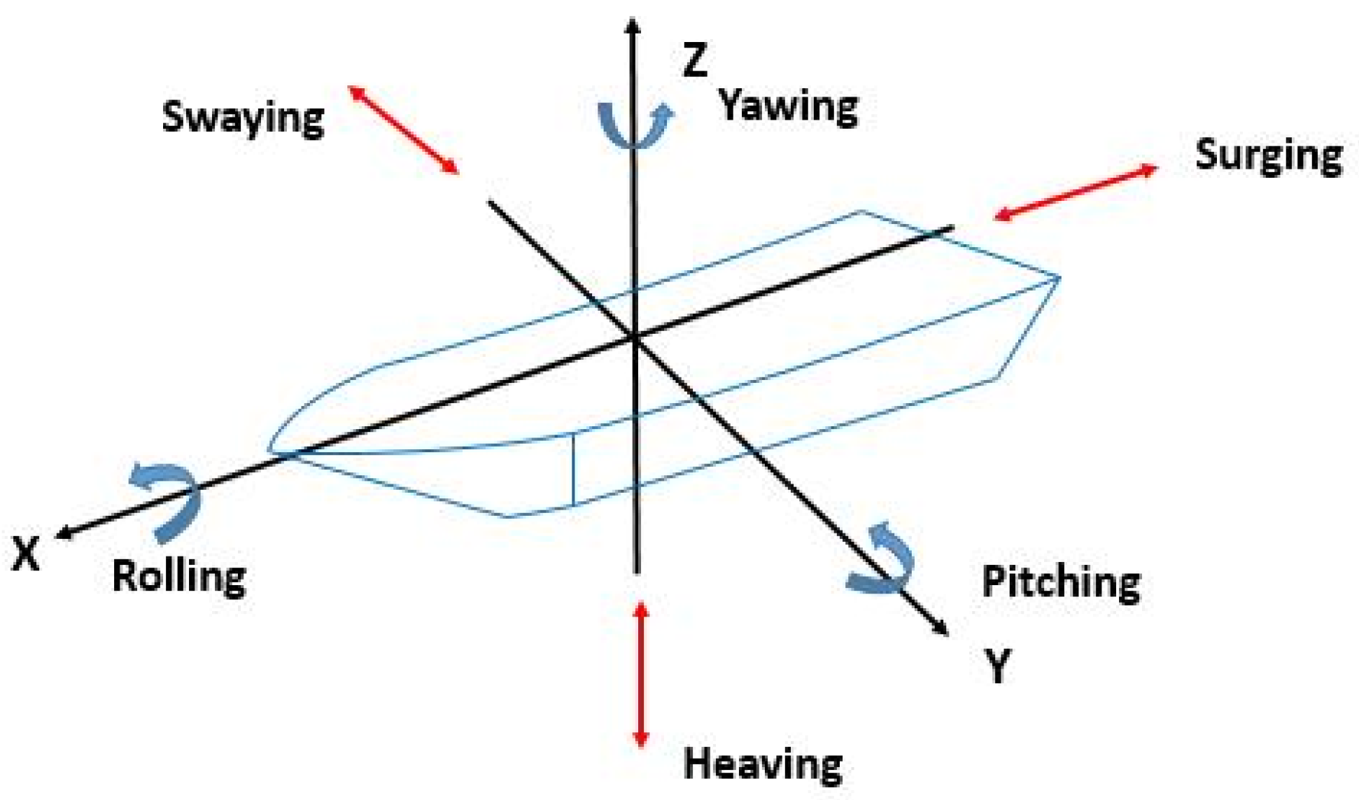
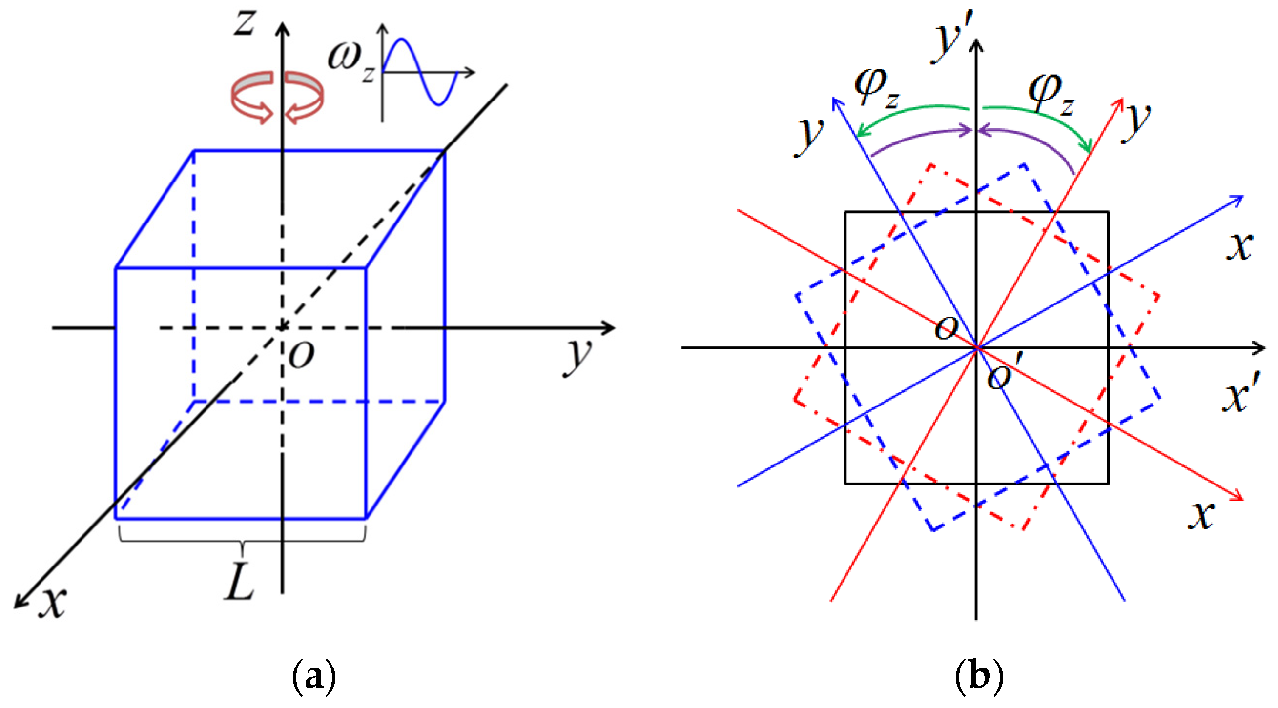
Multi-DoF motion is frequently encountered for different types of systems during sea transportation. Natural convection in multi-DoF motion system is frequently encountered with the heat exchangers mounted in marine or vehicles, either in heat exchangers of a ship, or the heating system in an oil tanker, or the circulation pipe in the nuclear reactor core. The six-DoF motions include rolling, pitching, yawing, swaying, heaving, and surging, as shown in Figure 1. Due to the influence of additional forces (Coriolis, tangential, centrifugal forces, etc.) caused by oscillating motion, the natural convection in such a system is more complex than that in a static system. The effects of ocean conditions on the thermal-hydraulic characteristics have attracted interest in recent years, some experiments and numerical simulations have been carried out, however, the simulations were only for some simple cases. Therefore, the general heat transfer characteristic of the system under multi-DoF motion is not clear and needs to be investigated. Natural convection in yawing motion is much simpler than that in other DoF-motion, since there is no angle effect. So in the paper, the characteristic of natural convection in yawing motion will be investigated systematically so as to investigate more complex heat transfer in other DoF motion.

1.1. Experimental and Numerical Simulations for Specific Applications

Most of the researches regarding the effect of harmonic rotation motion on heat and mass transfer were by experiments and confined to some specialized system (i.e., there were not fundamental researches). Although a few numerical researches were found in the open literature, they were limited to one-dimensional or two-dimensional cases, which were not sufficient to analyze the detailed flow and heat transfer behavior involved in the multi-DoF system. A large proportion of these researches concerned the flow and heat transfer in pipe flow or channel flow of a certain system under rolling or pitching motion. The experimental studies of Murata et al. [1] and Tan et al. [2] showed that the heat transfer coefficient of rolling conditions is greater than that of the non-rolling case, and the heat transfer coefficient of the rolling case increases with the increase in rolling amplitude and frequency. Yan [3,4] studied the heat transfer with laminar pulsating flow in a channel or tube in rolling motion, showing that the oscillating amplitude of Nusselt number increases with the increase of Prandtl number, and there is an approximate linear relation between the oscillating amplitude of Nusselt number and rolling frequency. Wang et al. [5] experimentally studied the single-phase heat transfer characteristics of pulsating flows induced by rolling motion in a circular pipe, indicating that the relative pulsation amplitude of Nusselt number increases with the increase of the maximum rolling angle, and decreases with the increase of rolling period and cycle-averaged flow rate, while the pulsating flow induced by rolling motion does not lead to significant variations in cycle-averaged heat transfer characteristics. Yuan et al. [6] found from their experiment that the average Nusselt number increases with the rolling amplitude and frequency in transitional flow regime, however rolling motion does not affect the Nusselt number in turbulent regime obviously. Yu [7] also found that rolling motion has influence on heat and fluid flow, but this influence is also dependent of the Reynolds number or flow regime. Yan’s numerical investigation [8] on the flowing and heat transfer characteristics of turbulent flow in tubes and rectangular channels in rolling motion also indicate that the Nusselt number is affected by rolling frequency, but the degree of influence also depend on the flow velocity.

1.2. Fundamental Researches

Fundamental study on the natural convection in rotation systems mainly concerned the constant-velocity rotation system, which is a special case for the harmonic rotation in this research. In these researches, the cavities rotate about either a horizontal axis [9,10,11,12,13,14,15] (orthogonal to the gravity axis) or a vertical axis [16,17,18,19]. These vertical rotations are the special cases (constant angular velocity) of yawing motion, which will be investigated in this study. It was reported in [15] that the effect of Coriolis force and centrifugal force are small but are differentiated from those of other forces. Baig [9] studied the natural convection in the horizontal rotating and differentially heated square enclosure, indicating that significant enhancement in heat transfer is achieved due to rotational effects. Jin [11] also showed that rotation enhances the heat transfer. Hamidy’s experimental and numerical research showed that that the Coriolis and centrifugal buoyancy forces arising from rotation have a remarkable influence on the local heat transfer when compared with the nonrotating results [10]. However, Tso [15] found that the effects of Coriolis force and centrifugal force on the natural convection are small by their numerical investigation on the natural convection in a horizontal-axis rotation cavity. Kumar [13] numerically studied the effect of Rayleigh number with rotation on the flow and heat transfer characteristics in a differentially heated enclosure rotating about the horizontal axis. For the vertical-axis rotation cases, it is also found that rotation has effect influence on the natural convection. Ker’s results [18] clearly revealed that significant reduction of heat transfer only occurs at low rotation rate, while high-speed rotation results in increase of heat transfer. Lee [19] numerically studied the transient three-dimensional mixed convection of air in a differentially heated vertical cubic cavity rotating about a vertical axis through the cavity center. The centrifugal and Coriolis forces were found to exhibit significant effects on the flow and heat transfer in the cavity when they are high enough. It was also found that the thermal buoyancy driven flow is strengthened at increasing centrifugal force but weakened in the near-wall regions by the increasing Coriolis force. The space average heat transfer from the isothermal plates is substantially reduced by the Coriolis force but is insensitive to the centrifugal force. Chori [16] investigated the laminar natural convection heat transfer in three-dimensional molten Lithium filled differentially heated enclosure, rotating about the vertical ridge is studied numerically. It was found that increase of the Taylor number significantly reduce the heat transfer, however, high rotational Rayleigh number values are found to significantly enhance the heat transfer. These constant-angular-velocity vertical rotations are the special cases of the yawing motion, which will be investigated in this study.
It is concluded from the above analysis that there are some experiment researches focusing on the natural convection undergoing oscillations, but these researches concerned some specialized cases which are not convenient for extrapolation and reference for application in different research area, and that numerical studies were one-dimensional or two-dimensional, and yawing motion cannot be described. Although the investigation for constant-velocity rotation is very mature and sufficient, large difference exists with the harmonic rotation. The harmonic rotation has some influencing factors such as Eulerian force and time-vary Coriolis force, so the characteristic should be much different. In this paper, a three-dimensional mathematical model for the natural convection under yawing motion will be established first of all, and the computer code will be developed and validated thereafter. With the validated code, the thermal and hydraulic characteristic of natural convection in a vertical-axis rotation system will be investigated; the influencing factors and sensitivity of natural convection to which will be clarified. This fundamental research should provide an effective reference for researchers in different research areas, since it is easy to extend to other fields, and the results are easy for reference in a different area.

2. Mathematical Modeling and Solution Method

2.1. Mathematical Model

The schematic representation of the physical system under investigation is shown in Figure 2. A cubic cavity which contains air as the working fluid is considered. Initially at time t = 0 , the enclosure is rolling about the z axis at φ = 0 and is isothermal at temperature T 0 . At time t > 0 , the wall temperatures of the enclosure are suddenly raised and lowered to some uniform constant temperature conditions in the following manner. The surface at y = 0.5 L is subjected to a uniform temperature T h and the surface at y = 0.5 L , is subjected to a different uniform temperature T c . The rest surfaces are thermally well insulated from the surroundings.
It is usually assumed that yawing motion is set as a sine function, i.e., φ = φ m sin ( 2 π / t c t ) , where φ is the angular position of the enclosure, φ m is the amplitude of the rolling, and t c is the period of the harmonic rotation. It should be noted that, the angular velocity is defined positive when it rotates counterclockwise, and the φ is defined positive in the first half of the cycle, and negative in the second half of the cycle.
Thus the air flow inside the enclosure is simultaneously driven by the harmonic rotation and the thermal buoyancy. By using the Boussinesq approximation [20] in which linear density variation with temperature (i.e., ρ = ρ 0 [ 1 β ( T T 0 ) ] ) is considered in both the body force and centrifugal force terms, the governing equations and boundary conditions become
( ρ 0 u ) x + ( ρ 0 v ) y + ( ρ 0 w ) z = 0
( ρ 0 u ) t + ( ρ 0 u u ) x + ( ρ 0 u v ) y + ( ρ 0 u w ) z = p e f f x + x ( μ u x ) + y ( μ u y ) + z ( μ u z )    ρ 0 Ω z 2 x β ( T T 0 ) + ρ 0 d Ω z d t y + 2 ρ 0 Ω z v ρ 0 d Ω z d t y β ( T T 0 ) ρ 0 Ω z v β ( T T 0 )
( ρ 0 v ) t + ( ρ 0 v u ) x + ( ρ 0 v v ) y + ( ρ 0 v w ) z = p e f f y + x ( μ v x ) + y ( μ v y ) + z ( μ v z )    ρ 0 Ω z 2 y β ( T T 0 ) ρ 0 d Ω z d t x 2 ρ 0 Ω z u + ρ 0 d Ω z d t x β ( T T 0 ) + 2 ρ 0 Ω z u β ( T T 0 )
( ρ 0 w ) t + ( ρ 0 w u ) x + ( ρ 0 w v ) y + ( ρ 0 w w ) z = p e f f z + x ( μ w x ) + y ( μ w y ) + z ( μ w z ) + ρ 0 g β ( T T 0 )
p e f f x = p x ρ 0 Ω z 2 x ,   p e f f y = p y ρ 0 Ω z 2 y ,   p e f f z = p z ρ 0 g
p e f f = p ρ 0 [ x y d Ω z d t + 0.5 Ω z 2 ( x 2 + y 2 ) + g z ]
Energy equation:
( ρ 0 T ) t + ( ρ 0 u T ) x + ( ρ 0 v T ) y + ( ρ 0 w T ) z = x ( λ c p T x ) + y ( λ c p T y ) + z ( λ c p T z )
In Equations (1)~(7), u, v, and w are three velocity components defined on the coordinates x, y, and z rotating with the cavity, as shown in Figure 2, Ω denotes the time-varying rotation angular velocity, T represents the temperature of the fluid, λ and c p are thermal conductivity and heat capacity respectively, p e f f is the effective pressure, ρ 0 and β are reference density and thermal expansion factor of the air respectively. The forces on the right-hand side of Equations (2) and (3) will be explained in Equations (10) and (11).
The corresponding initial and boundary conditions are
t < 0 , u = 0 , v = 0 , w = 0   a n d   T = T 0 = T h   f o r   a l l   x , y , z t 0 , x = L / 2      u = v = w = 0 , T x = 0 x = L / 2      u = v = w = 0 , T x = 0 y = L / 2      u = v = w = 0 , T = T h y = L / 2      u = v = w = 0 , T = T c z = L / 2      u = v = w = 0 , T z = 0 z = L / 2      u = v = w = 0 , T z = 0
To derive the non-dimensionless governing equations, the following non-dimensional variables are defined.
Y = x L ,   Y = y L ,   Z = z L ,   U = u L α ,   V = v L α ,   W = w L α ,   Θ = T T c T h T c ,   τ = t α L 2 , P = p e f f L 2 / ρ 0 α 2 ,   Ta ˜ = 4 ( 2 π / t c ) 2 L 4 ν 2 ,   Ra = g β ( T h T c ) L 3 ν α , Ra ω ˜ = ( 2 π / t c ) 2 H β ( T h T c ) L 3 ν α .
Here, X , Y and Z indicate the dimensionless coordinates; U , V and W are dimensionless velocity profiles; α is the thermal diffusivity ( α = λ / ( ρ c p ) ), Θ denotes the dimensionless temperature; Ta ˜ is defined as the nominal Taylor number describing the general strength of the harmonic rotation motion, in a similar way with the definition of Taylor number for constant-velocity rotation; Ra ω is defined as the nominal rotation Rayleigh number in the harmonic rotation system.
With the dimensionless parameters defined above, the governing equations, initial and boundary conditions then become
U X + V Y + W Z = 0
U τ + ( U U ) X + ( U V ) Y + ( U W ) Z = P X + Pr ( 2 U X 2 + 2 U Y 2 + 2 U Z 2 ) Pr Ra ω Θ X φ m 2 cos 2 ( 0.5 Ta ˜ 0.5 Pr τ ) c e n t r i f u g a l   b u o y a n c y   f o r c e 0.25 T a ˜ Pr 2 Y φ m sin ( 0.5 T a ˜ 0.5 Pr τ ) t a n g e n t i a l   f o r c e + Ta ˜ 0.5 Pr V φ m cos ( 0.5 Ta ˜ 0.5 Pr τ ) C o r i o l i s   f o r c e + Pr R a ω Θ Y φ m sin ( 0.5 T a ˜ 0.5 Pr τ ) t a n g e n t i a l   b u o y a n c y   f o r c e 4 T a ˜ 0.5 R a ω Θ V φ m cos ( 0.5 T a ˜ 0.5 Pr τ ) C o r i o l i s   b u o y a n c y   f o r c e
V τ + ( V U ) X + ( V V ) Y + ( V W ) Z = P Y + Pr ( 2 V X 2 + 2 V Y 2 + 2 V Z 2 ) Pr Ra ω Θ Y φ m 2 cos 2 ( 0.5 Ta ˜ 0.5 Pr τ ) c e n t r i f u g a l   b o y a n c y   f o r c e + 0.25 T a ˜ Pr 2 X φ m sin ( 0.5 T a ˜ 0.5 Pr τ ) t a n g e n t i a l   f o r c e Ta ˜ 0.5 Pr U φ m cos ( 0.5 Ta ˜ 0.5 Pr τ ) C o r i o l i s   f o r c e Pr R a ω Θ X φ m sin ( 0.5 T a ˜ 0.5 Pr τ ) t a n g e n t i a l   b u o y a n c y   f o r c e + 4 T a ˜ 0.5 R a ω Θ U φ m cos ( 0.5 T a ˜ 0.5 Pr τ ) C o r i o l i s   b u o y a n c y   f o r c e
W τ + ( W U ) X + ( W V ) Y + ( W W ) Z = P Z + Pr ( 2 W X 2 + 2 W Y 2 + 2 W Z 2 ) + Pr Ra Θ
( Θ ) τ + ( U Θ ) X + ( V Θ ) Y + ( W Θ ) Z = 2 Θ X 2 + 2 Θ Y 2 + 2 Θ Z 2
Accordingly, the dimensionless boundary conditions become
t < 0 , U = 0 , V = 0 , W = 0   a n d   Θ = 0   f o r   a l l   X , Y , Z t 0 , X = 0.5      U = V = W = 0 ,   Θ X = 0 X = 0.5      U = V = W = 0 ,   Θ X = 0 Y = 0.5      U = V = W = 0 , Θ = 1 Y = 0.5      U = V = W = 0 , Θ = 0 Z = 0.5      U = V = W = 0 , Θ Z = 0 Z = 0.5      U = V = W = 0 , Θ Z = 0
The above formulations indicate that the flow and heat transfer to be examined is governed by the Prandtl number Pr, nominal Taylor number T a ˜ , Rayleigh number Ra and nominal rotational Rayleigh number Ra ω ˜ , here Ra ω ˜ = Ra ( 2 π / t c ) 2 L / g . Hence the rotational buoyancy becomes important when the rotating speed is high or when cavity size is large, that is when ( 2 π / t c ) 2 L is much larger than g . In addition to examining the time evolution of the velocity and temperature fields, results for the local and space-average Nusselt numbers Nu and Nu ¯ on the heated or cooled plates are important in thermal design and can be evaluated from Equations (15) and (16), respectively.
Nu = Θ Z | Z = Z min , Z = Z min
Nu ¯ = Y min Y max X min X max Θ Z d X d Y .

2.2. Solution Method

The highly nonlinear and coupled Equations (9)–(13), with the corresponding boundary conditions, Equation (12), are discretized in the framework of the finite volume method on a 3D non-staggered grid shown in Figure 3. To resolve the steep velocity and temperature gradients in the near-wall region, non-uniform grid was used. Specifically, the grid lines passing through volume size in each direction satisfies a sine function, XCV(I) = 1.0×SIN(FLOAT(I)/L1×3.14159), and then XCV(I) = XCV(I) ×∑XCV(I)/, here L1is the number of the nodes in each dimension (x, y, z) and I is the sequence number of the nodes. The convection terms are discretized by a stability-guaranteed second-order difference (SGSD) scheme [21], and the diffusion terms are discretized by the central differencing scheme. The resulting discretized equations were solved by a computer code which was developed by the author based on the IDEAL algorithm [22], which is found to show good convergence.

2.3. Code Validation

In view of the complex flow and heat transfer to be investigated, stringent validation tests should be performed to verify the computer code developed. For this purpose, our numerical code is validated against well-known Ansys Fluent results in yawing motion and against those reported in the literature regarding the natural convection flow within cubic enclosure filled with air undergoing vertical-axis rotation with constant-velocity. The vertical-axis rotation with constant-velocity is a special case of the harmonic rotation in this research.
First, the code results were compared with Ansys Fluent results calculated based on dynamic mesh, with R a = 1 × 10 6 and t c = 1 s . Since dynamic mesh method and inertial coordinate system method are two independent methods, this validation is meaningful. Figure 4 shows the comparison between code results and Ansys Fluent results, in which the left column corresponds to the Ansys Fluent results and right column corresponds to the code results. In this figure, (+) and (-) indicates the clockwise rotation and counterclockwise rotation respectively. Good agreement can be found from this comparison. In addition, similar numerical simulations are performed with the same parameters in Lee’s research [19]. The Nusselt number on both hot boundary and cold boundary are compare in Table 1. It is found that both results are in good agreement.
With the validation above, the results of the numerical procedure proposed in this research is believable. With the validated code, the test cases in Table 2 will be studied one by one. The results and findings are discussed in the rest part of this paper.

3. Results and Discussions

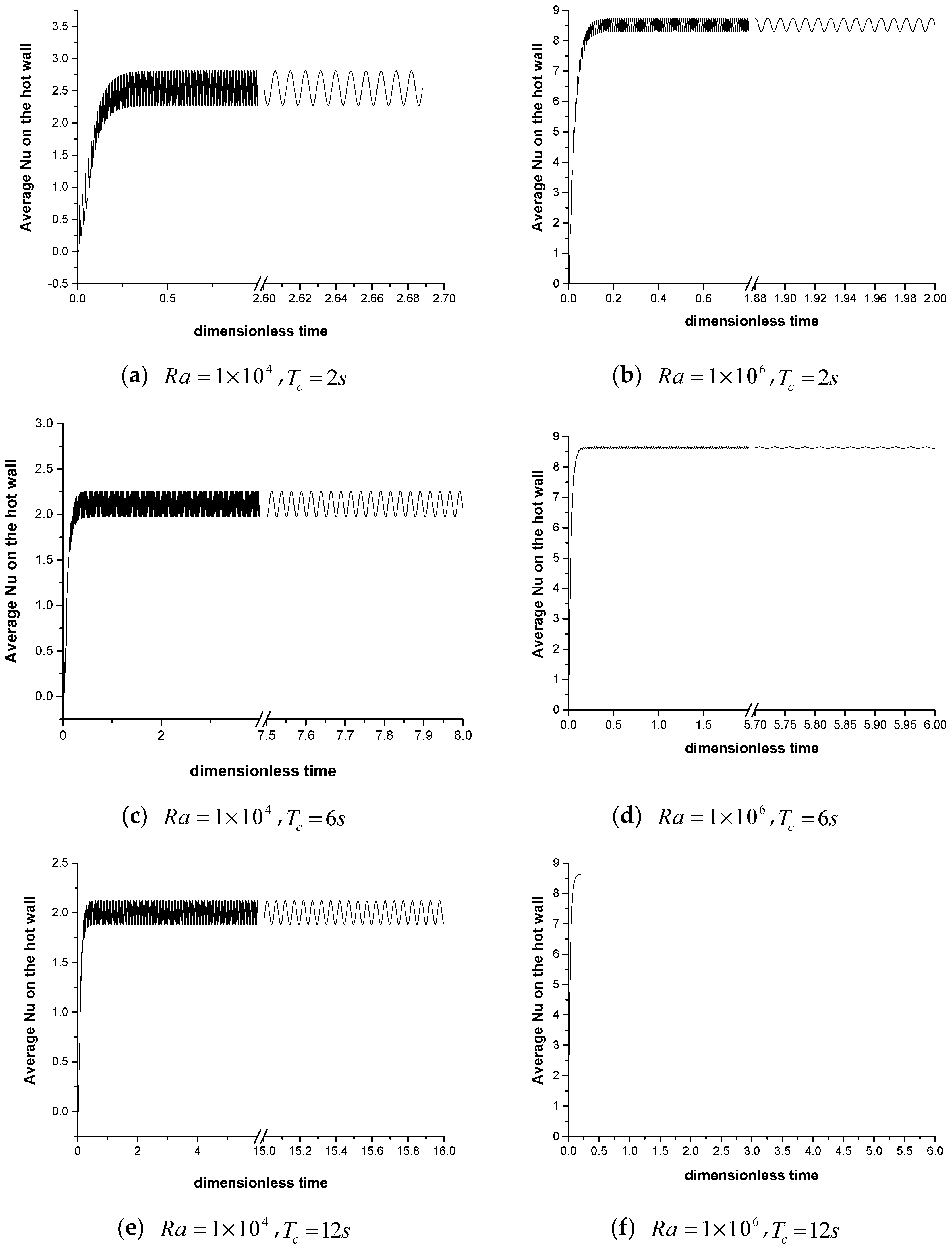
In contrast to the stationary case, the harmonic rotation introduces Coriolis forces, centrifugal forces, the Eulerian forces, and the buoyancy caused by these forces. So the characteristic of the natural convection under the interactive effect of these forces is much more complex than that in static case. Therefore, in this part, the characteristic of the natural convection under the coupling effect of these forces will be studied and the effect of the harmonic rotation on the flow and heat transfer will be clarified. According to Equations (9)–(13), the dimensionless parameters governing this kind of flows are Rayleigh number (Ra), Prandtl number (Pr), nominal rotational Rayleigh number (Raw), and nominal Taylor number (Ta). The Pr is chosen to be 0.71, which corresponds to the air. An appropriate choice of other parameters is required to obtain stable and converged solutions. Hence, for this purpose we have chosen these parameters as listed in Table 2, in which 12 cases are designed with different combinations of influencing factors. The 12 cases are calculated and the results are analyzed.
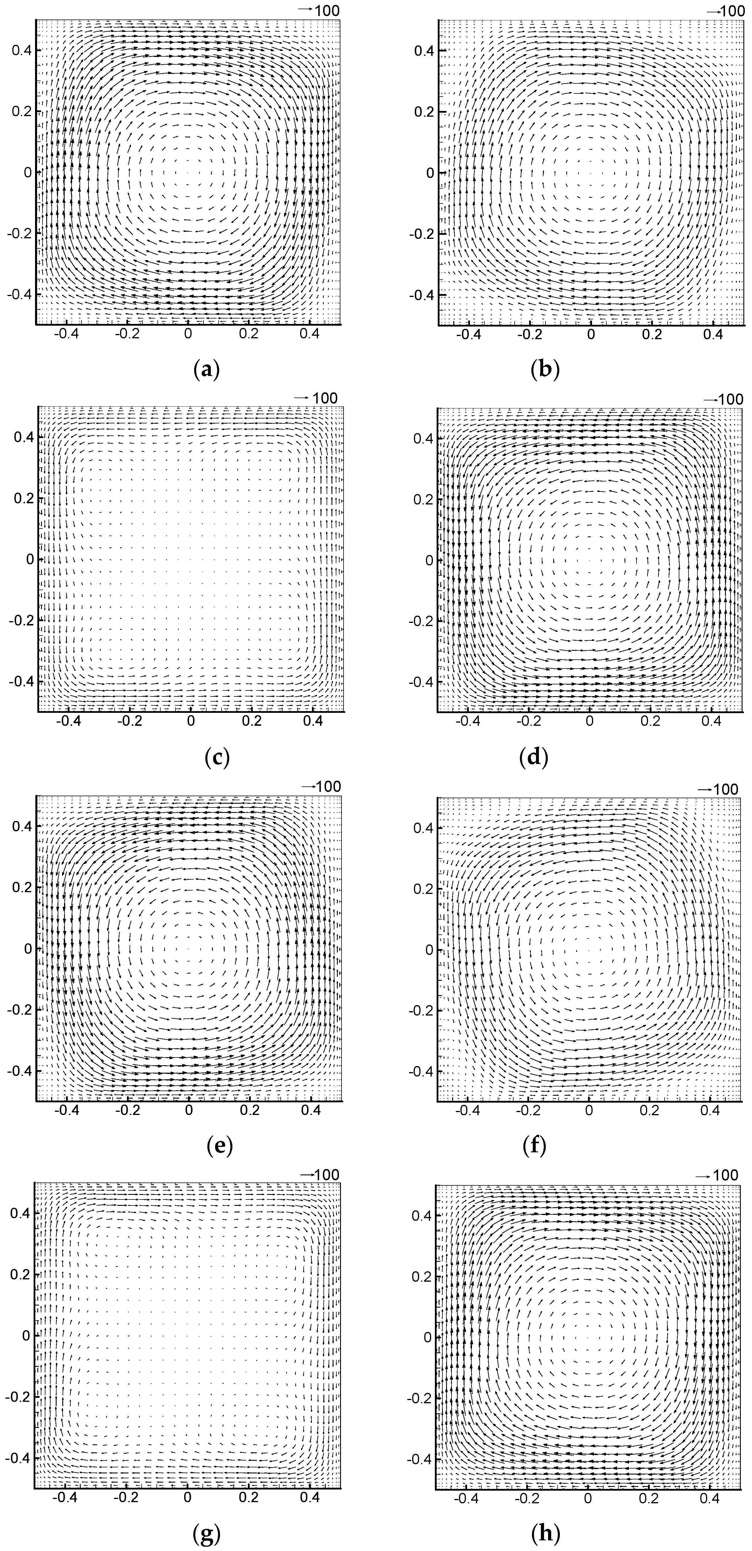
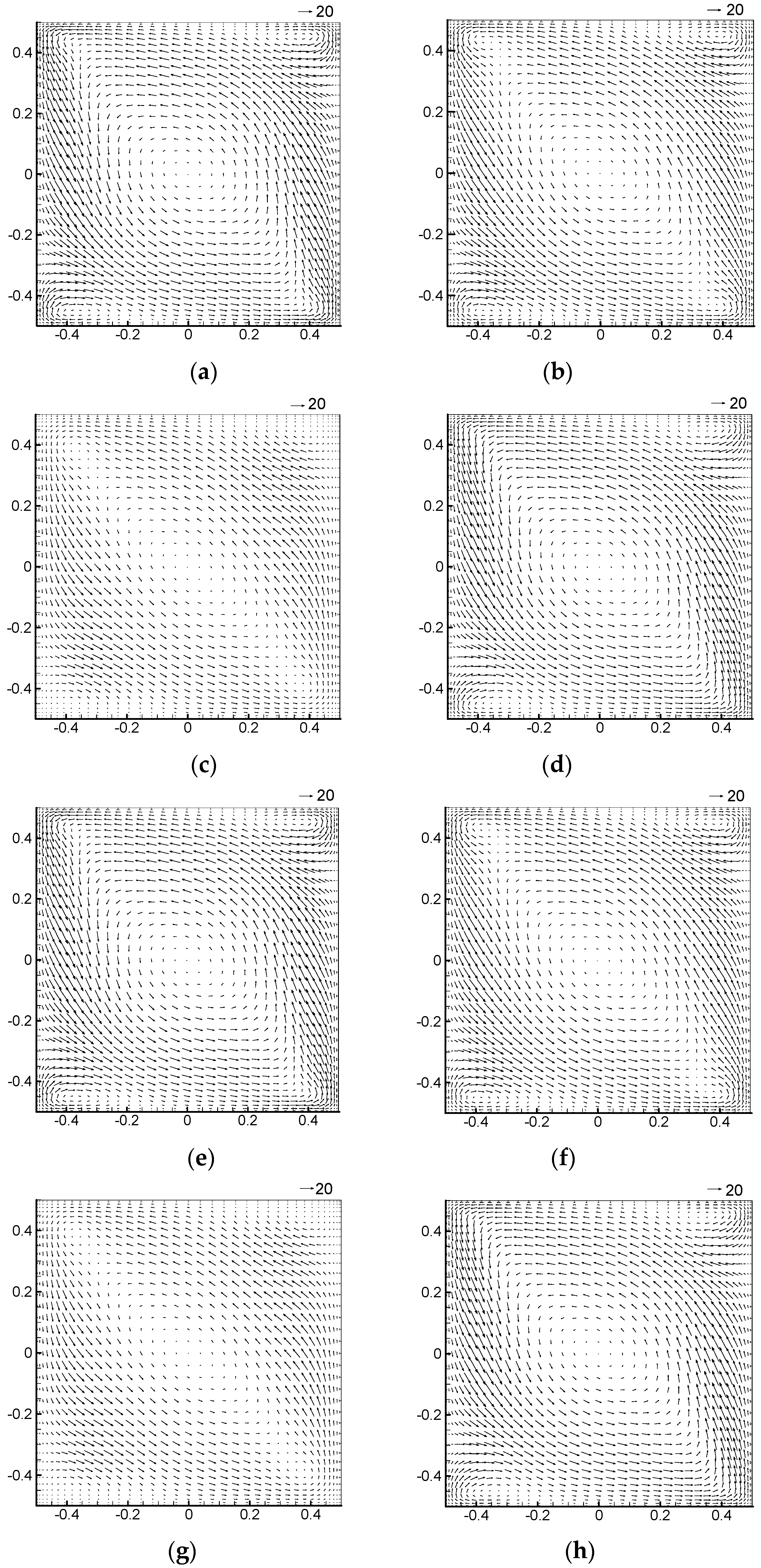
Figure 5 shows the velocity vector distributions in the x-o-y plane at Z = 0.5 for Case 1. In the figure, φ is the rotation angle as shown in Figure 2b, and (+) and (-) indicates the clockwise rotation and counterclockwise rotation respectively. It can be seen from the figure that due to the periodic change in the magnitude and direction of the Eulerian force, the magnitude and direction of the velocity also change correspondingly. The direction of the Eulerian force is opposite to the direction of the tangential acceleration, so in the first half of the cycle, the counterclockwise angular velocity gradually increases, and when it reaches 1/2 cycle, it increases to the maximum (Figure 5e). In the second half of the cycle, due to the change of the direction of the Eulerian force, the clockwise velocity began to accumulate, and when it reaches the whole cycle, the clockwise velocity reaches the maximum (Figure 5a). Form counterclockwise circulation to clockwise circulation, there is a transition state at which the counterclockwise velocity was almost weakened by the opposite-direction velocity, as shown in 
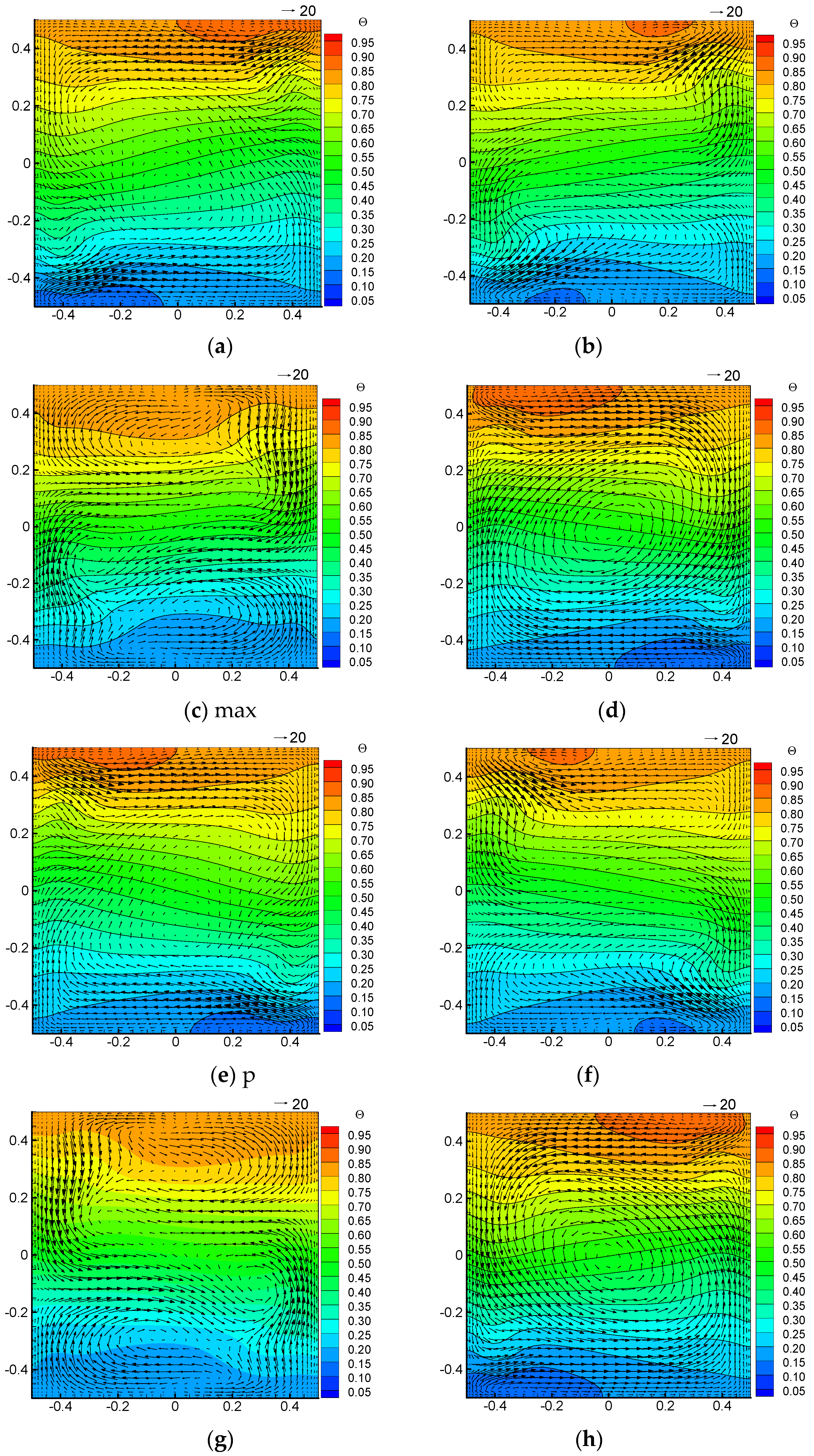
Figure 5c,g. After that, the clockwise velocity dominates the whole flow gradually. Since the Eulerian forces are larger at the position farther away from the rotation axis, so the transition appear firstly near the wall and then in the core region. It can also be found from the figure that the thickness of the flow boundary layer increases or decreases periodically, being thinnest at the amplitude position and the largest at the equilibrium position. This is because the Coriolis force, pointed to the rotation axis, is the largest and smallest at the equilibrium position and amplitude position, respectively.
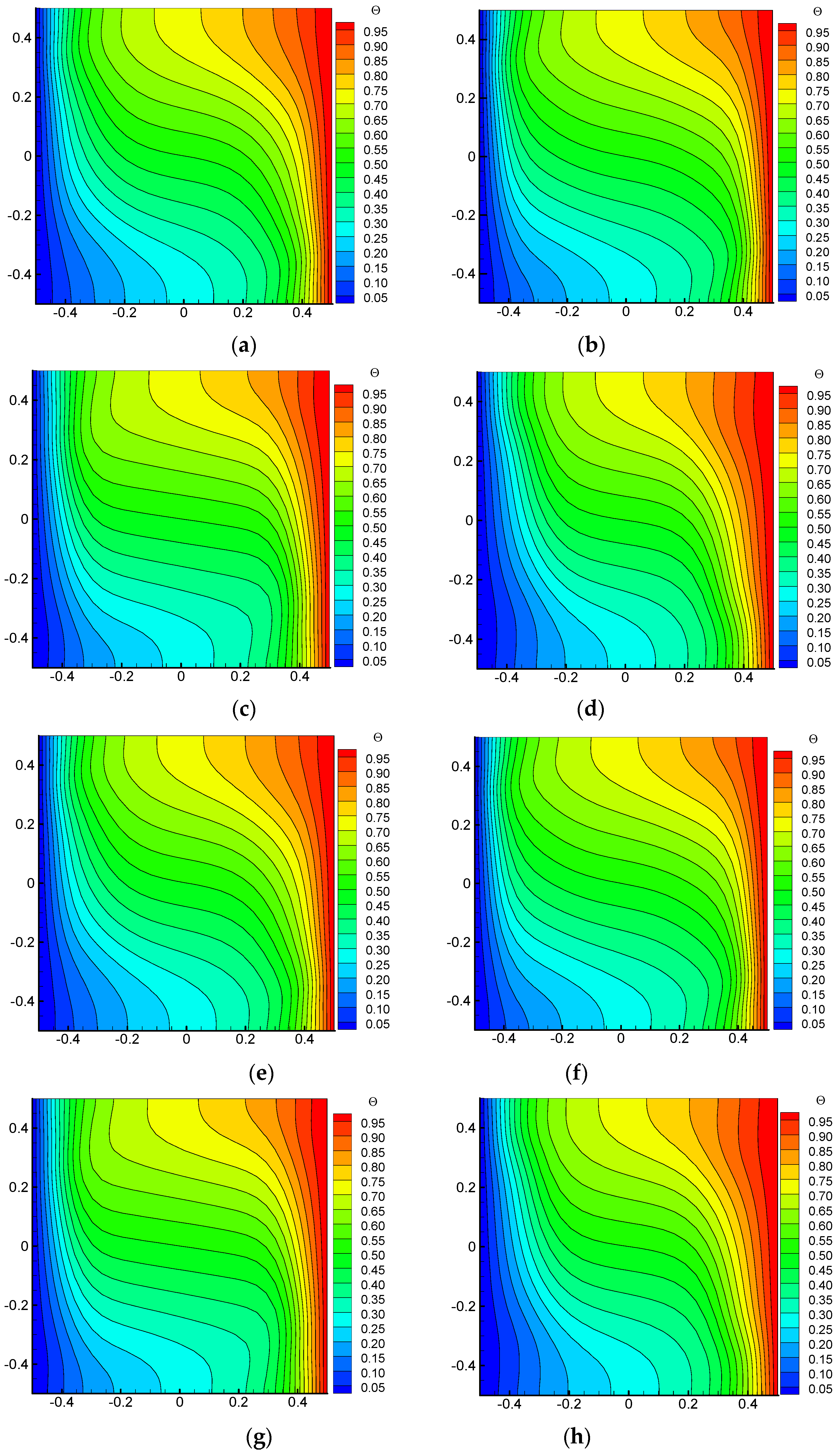
Due to the angular velocity in x-o-y plane, the temperature fields in this plane also show the rotation effect, as shown in Figure 6. 
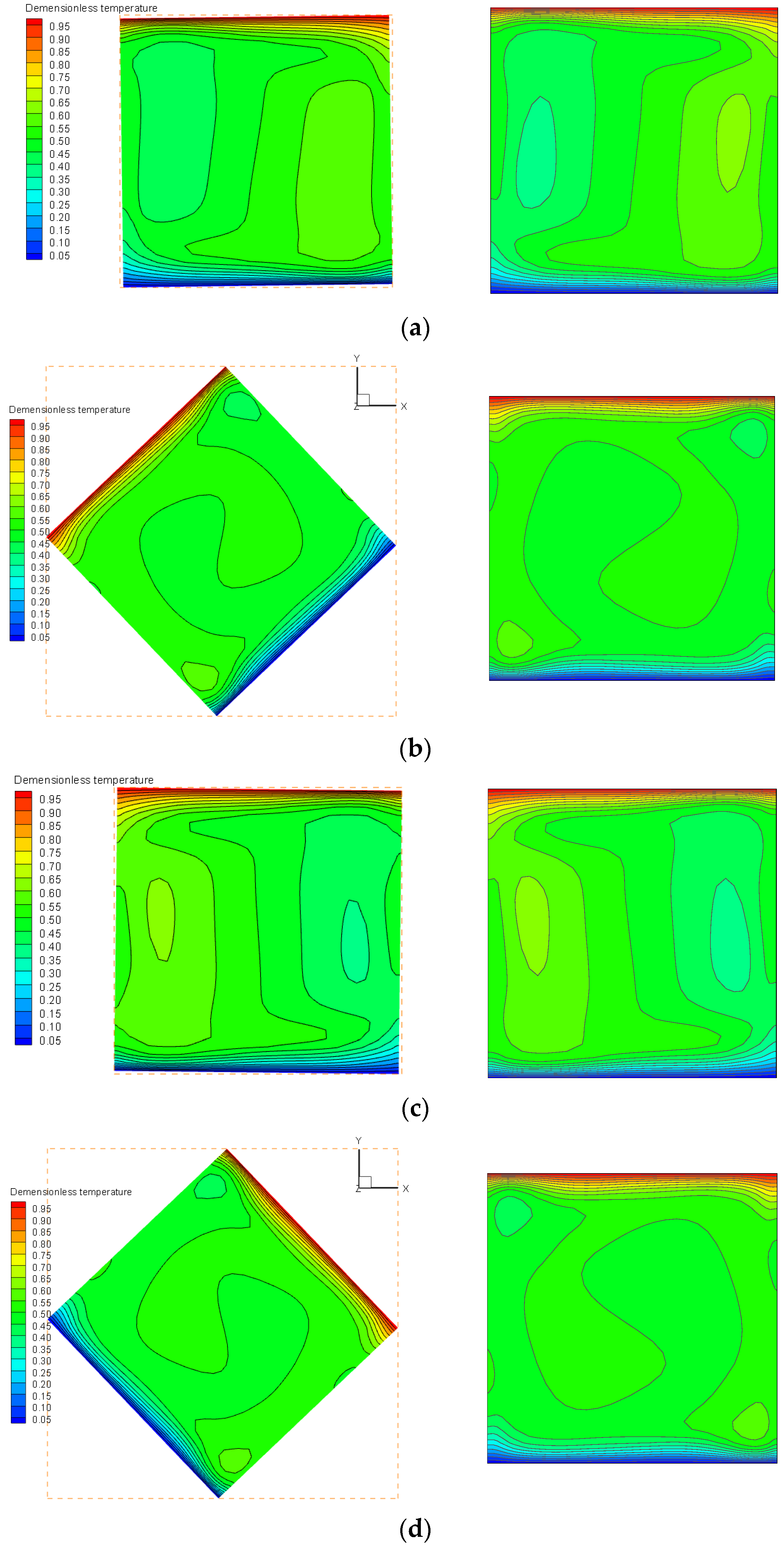
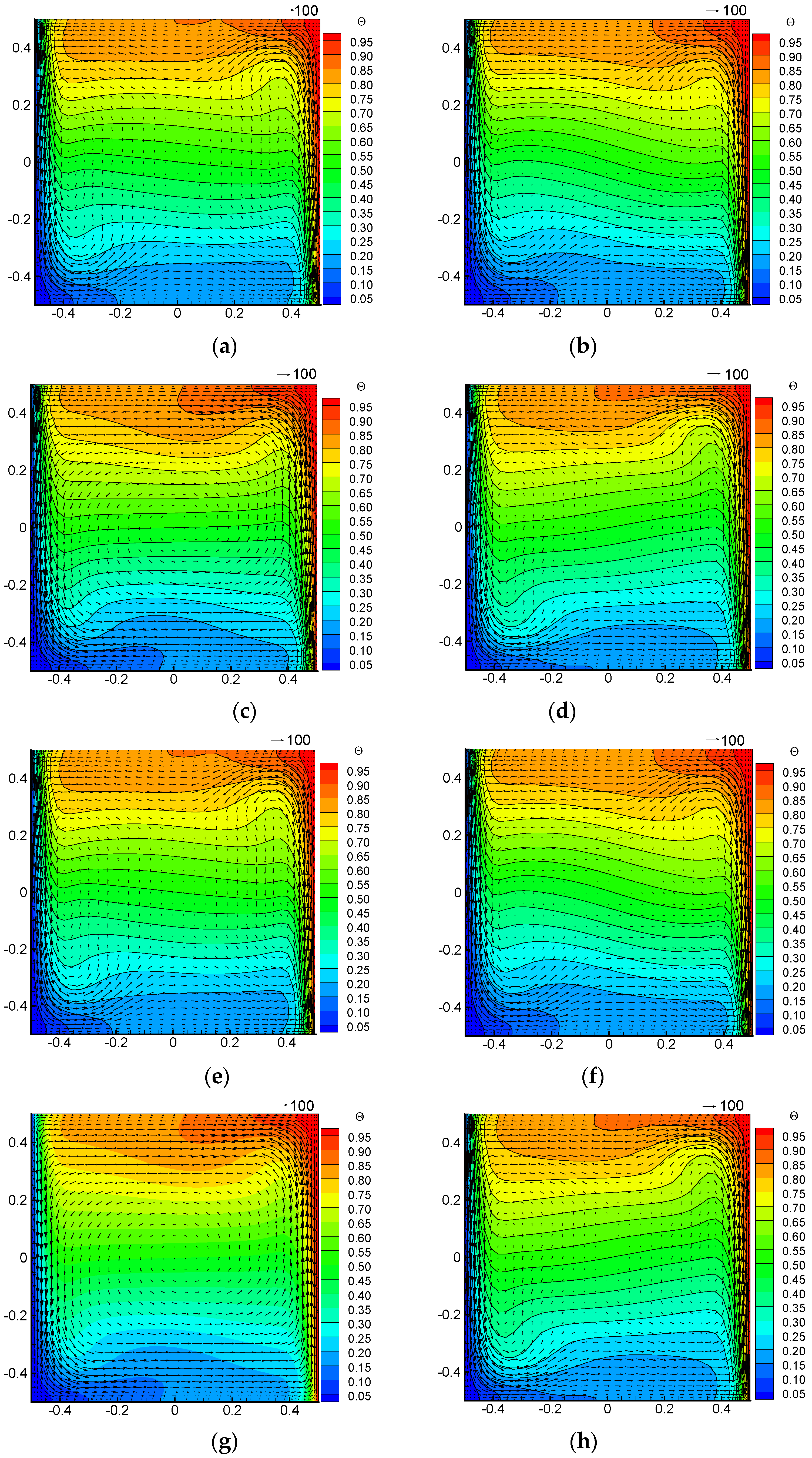
Figure 6 shows the temperature fields in x-o-y plane at Z = 0.5. It can be seen that the hot and cold boundaries present a larger influencing region due to the rotation effect. It can also be found that the thickness of the thermal boundary layer changes periodically with the rotation.
The periodical clockwise and counterclockwise flows in the x-o-y plane will be subjected to a Coriolis force pointing to the rotation axis. The counterclockwise velocity induced by gravitational buoyancy in the y-o-z (higher temperature on the right) will be pulled towards the rotation axis (z axis) periodically due to rotation, presenting an elliptical motion trajectory as shown in Figure 7. This motion trajectory is different with those in static case. As can be seen from Figure 7, when the Coriolis force is large, the flows near the left and right boundaries move closer to the rotation axis, resulting in a thicker flow boundary layer. When the Coriolis force is zero, the flow boundary layer becomes very thin, and the thickness of the boundary layer changes periodically. Similarly the temperature field also presents a thermal boundary layer changing periodically, as shown in Figure 8.
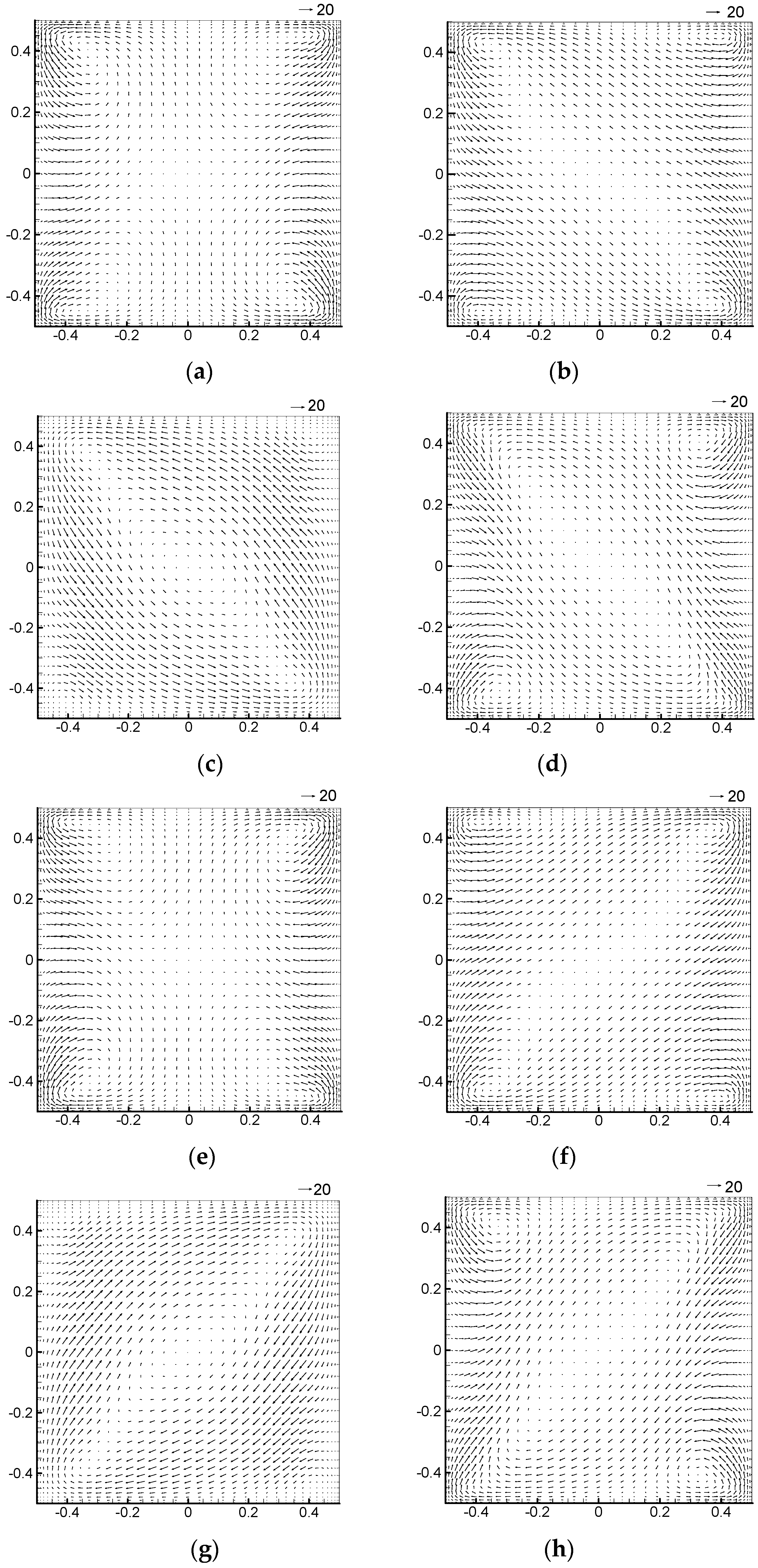
Figure 9 shows the velocity field in the x-o-z plane at y = 0.5. It can be seen from the figure that the velocity vector is mainly dominated by the natural convection in the square cavity, which is still counterclockwise. Such a velocity field results in the flow field as shown in Figure 10.
As can be seen from the vector distributions in the three planes, the Eulerian force-induced velocity is far greater than gravitational buoyancy-induced velocity. Therefore, the change of Eulerian force will seriously affect the change of flow field.
The above analysis is regarding the flow and heat transfer at low Rayleigh number, and in the following part the situation of larger Ra will be discussed.
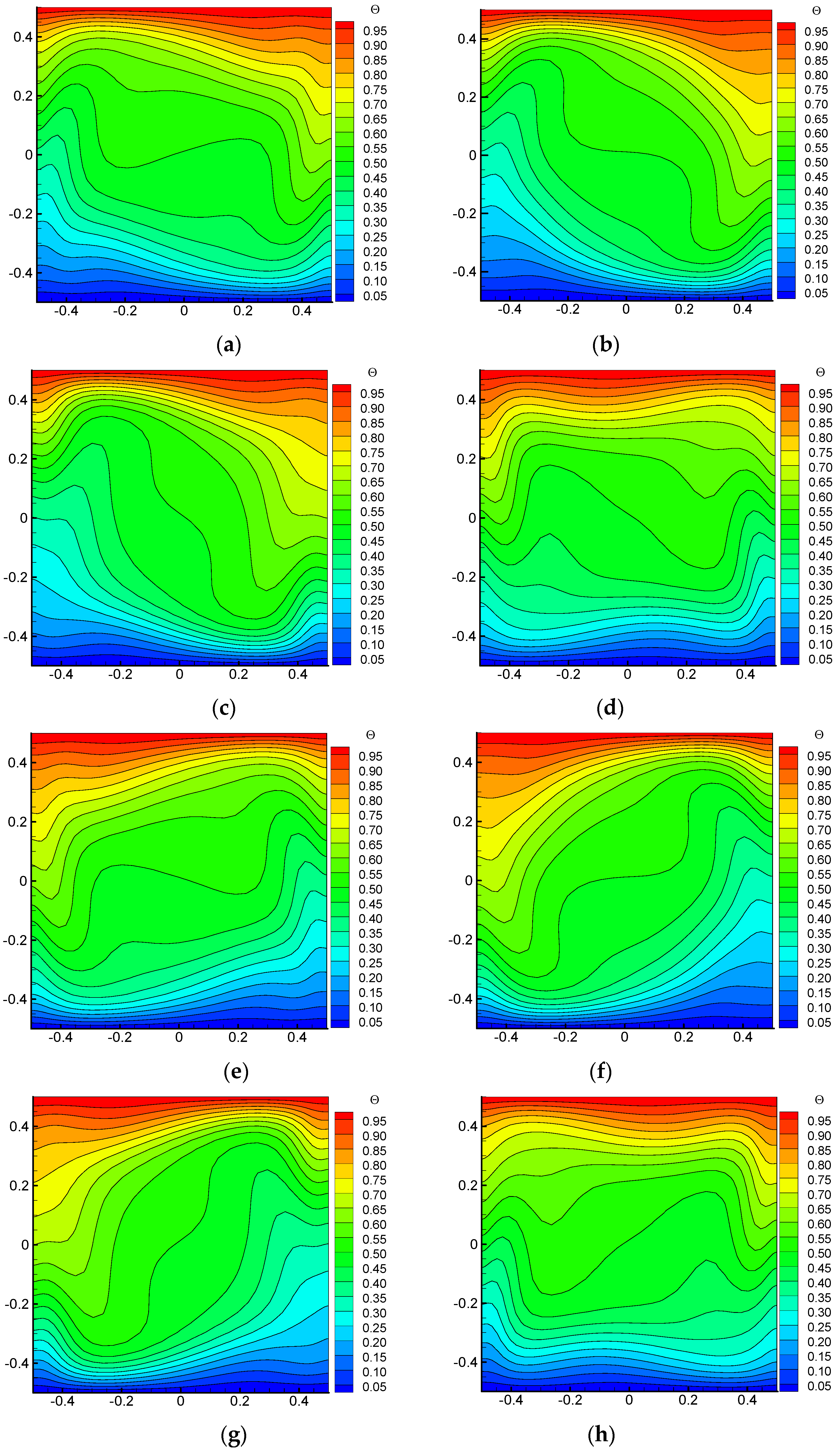
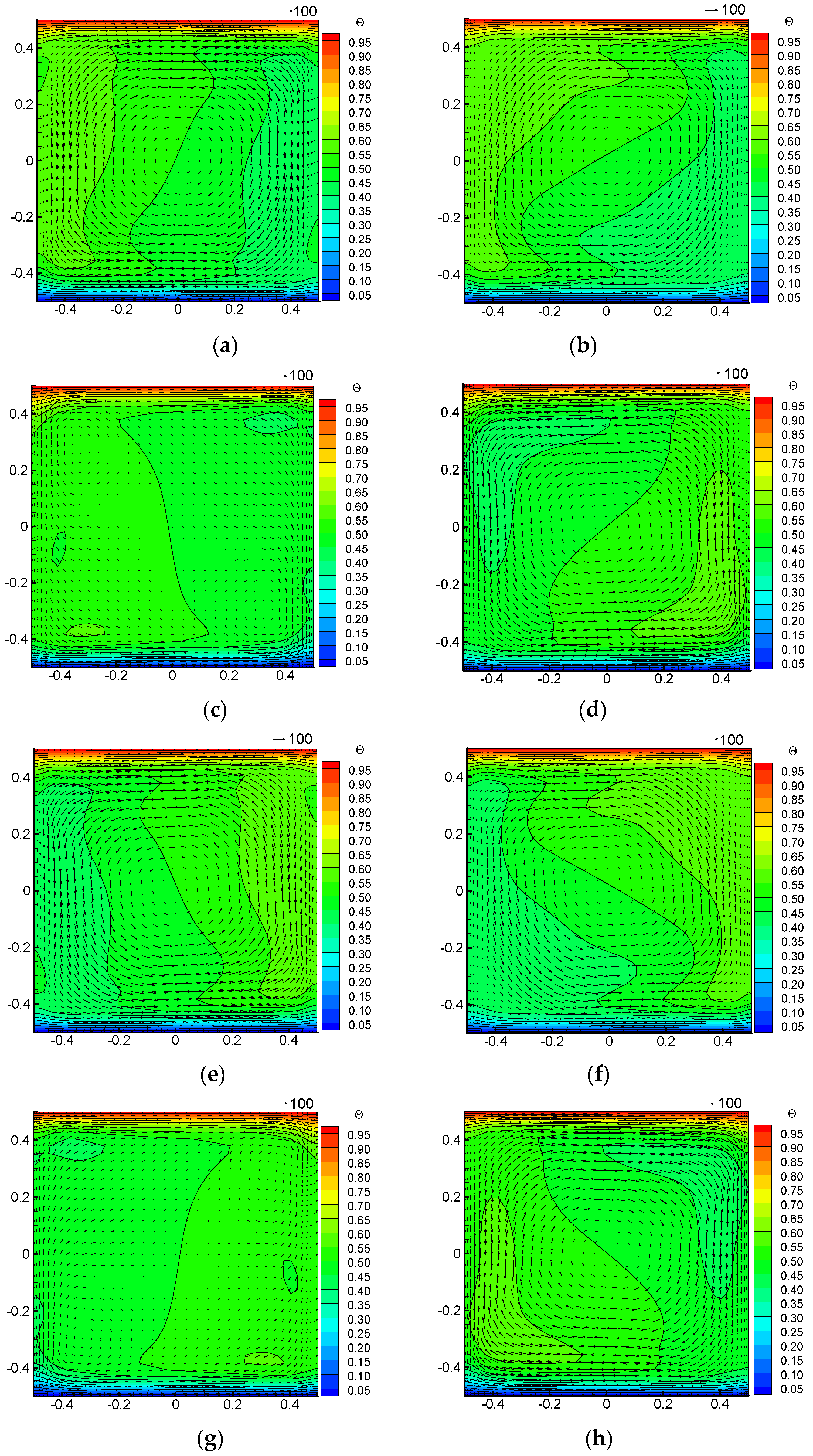
 Figure 11, Figure 12 and Figure 13 show the velocity vector distributions and temperature fields in plane x-o-y, plane y-o-z and plane x-o-z, respectively, when the Ra increases to 106 (Case 4). Compared with Figure 5, it can be seen from the Figure 11, Figure 12 and Figure 13 that when the Rayleigh number is larger, the flow boundary layer and the thermal boundary layer will become thinner due to the enhancement of natural convection, as shown in Figure 11 and Figure 12. Moreover, the temperature field at y-o-z plane is stratified, resulting in a uniform temperature distribution in the core region in x-o-y plane. Due to the strong flow generated by natural convection in the square cavity, the flow field formed in the x-o-z plane is also relatively complex. Moreover, with the influence of periodical Coriolis, the velocity is periodically pulled towards the rotation axis. It can also be seen from the figure that the flow intensity of natural convection is slightly higher than that generated by the Eulerian force, so with this Rayleigh number, the flow is dominated by natural convection.
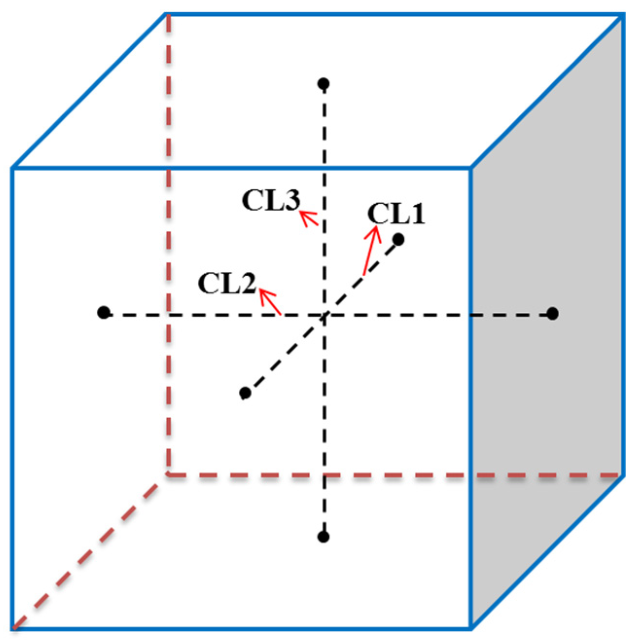
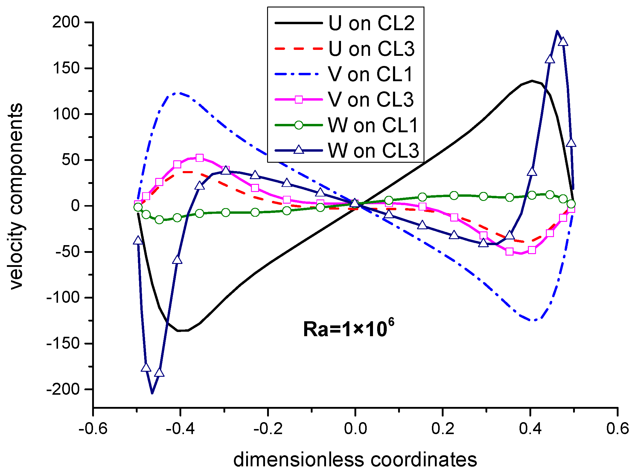
From the perspective of velocity fields and temperature fields, the flow and heat transfer characteristics in a vertical-axis rotation system are comparatively studied between a higher Ra and a lower Ra. It can be found from the figure that the flow and heat transfer characteristics are more complicated than those of static case due to the Eulerian force, Coriolis force, centrifugal force generated by rotation and the buoyancy force introduced by these forces. When the rotation-induced velocity is stronger than that induced by gravitational buoyancy, the flow and heat transfer characteristics are seriously affected by rotation. However, when natural convection is dominated, the effect of rotation is not as significant as that of lower Ra. In order to compare the velocity dominance under different Ra conditions, velocity profiles on three center lines of the cavity shown in Figure 14 are compared. 
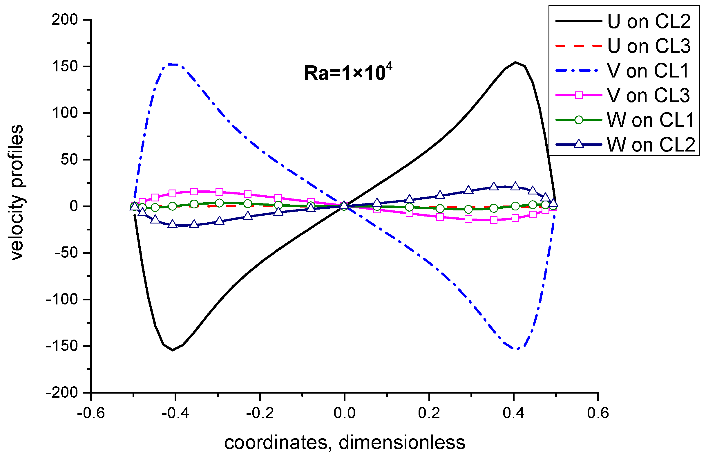
Figure 15 shows the velocity profiles on the three center lines when Ra is 1.0 × 10 4 . It can be seen from the figure that the velocities U and V in x-o-y plane caused by rotation dominate the flow, while the flow caused by natural convection and other forces are obviously weaker than that generated by rotation. Figure 16 shows the velocity distribution on three center lines when Ra is 1.0 × 10 6 . As can be seen from the figure, the z-direction velocity caused by natural convection dominates the flow, followed by the velocity caused by rotation. Therefore, when the Rayleigh number is 1.0 × 10 4 , rotation-induced velocity dominates the flow, while at 1.0 × 10 6 , natural convection-induced velocity dominates the flow.
In the following part, the heat transfer characteristics of natural convection under different Ra, rotation period t c and amplitude φ m will be comparatively investigated from the perspective of boundary heat transfer rate. 
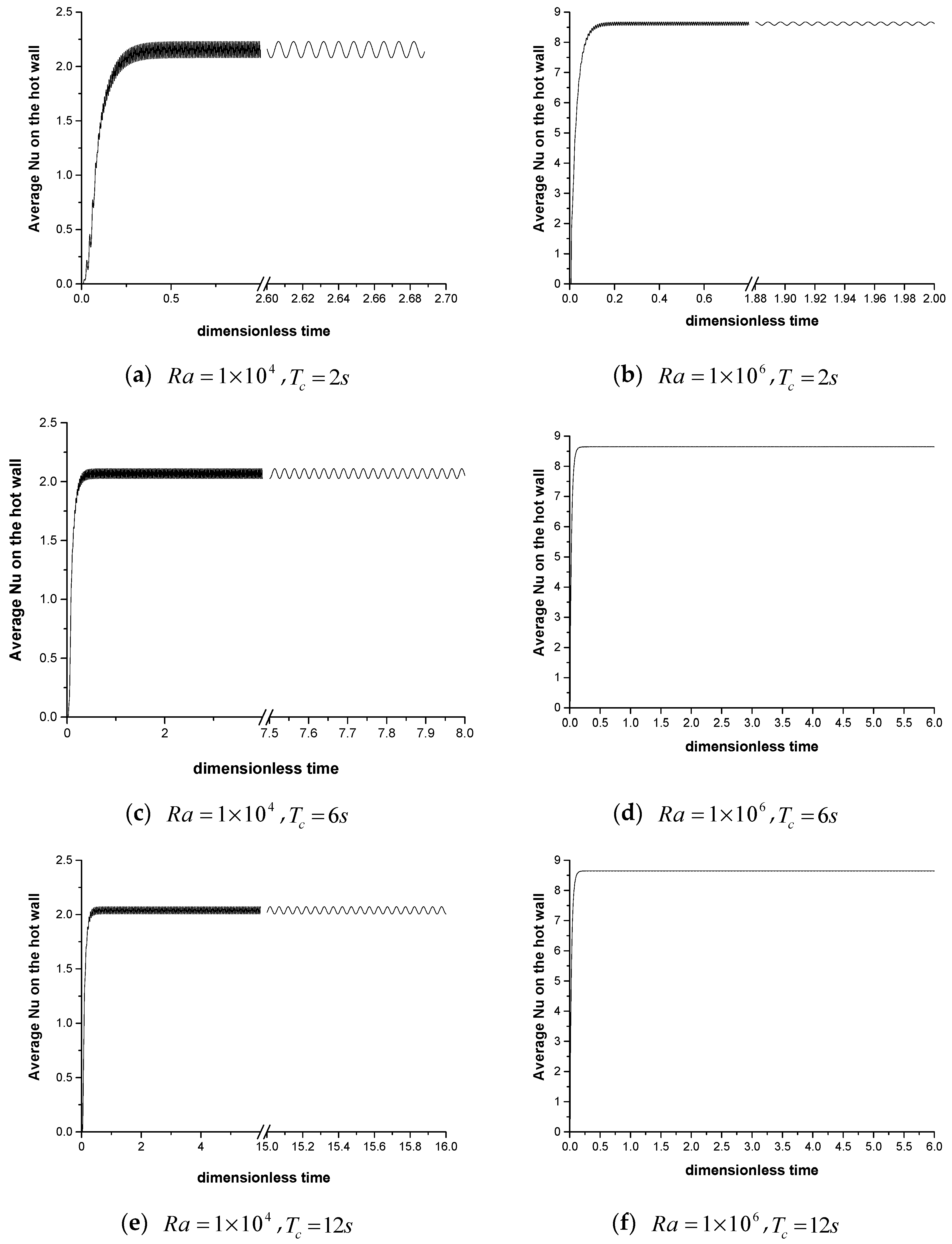
Figure 17 compares the hot-boundary Nu under different Ra and rotation periods with amplitude of π / 4 . The left and right columns of the figure correspond to Ra of 1.0 × 10 4 and 1.0 × 10 6 , respectively. As can be seen from the figure, when the Rayleigh number is low, the hot-boundary Nu decreases with the increase of the period, that is, the hot-boundary Nu is proportional to the rotation frequency; however, when Ra is higher, changing the period of the rotation within a certain range has no obvious influence on Nu on the hot boundary. This is because the flow rate is dominated by rotation at low Ra, while the flow is dominated by natural convection at high Ra. In addition, under the same Rayleigh number, the smaller the period, the greater the range of the hot-boundary Nu. Figure 18 shows the results for a smaller amplitudes, π / 8 . Compared with Figure 17, it can be found that the Nu is larger if the amplitude is larger, with other parameters remaining same.

4. Conclusions

The tangential force (Euler force) and Coriolis force induced by harmonic rotation have important effect on the natural convection in a vertical-axis harmonic rotation system. The periodical-changing tangential force results in circle-like flow circulation in x-o-y plane, and this circulation is either clockwise or clockwise or a transition one. This rotation-induced circulation will be subjected to Coriolis force which is pointed to rotation axis. As a result, the velocities induced by gravitational buoyancy near the hot and cold wall will be pulled periodically towards the rotation axis due to the Coriolis force, and the boundary layer becomes thicker or thinner periodically due to the change in Coriolis force. Consequently, the Nusselt number on the hot and cold boundary varies periodically: At φ = 0 , Coriolis force is the largest and the boundary layer is the thickest, and at φ = φ m , the Coriolis is the smallest, so the boundary layer is thinnest and thus the Nusselt number is highest. On the other hand, the Nusselt number is also positively influenced by the angular velocity near the hot boundary. With the same Ra, the larger the rotation frequency, the higher the Nusselt number. However, the effect of rotation on natural convection also depends on the relative magnitudes of rotation-induced velocity and buoyancy-induced velocity: when the rotation-induced velocity dominates the flow, the harmonic rotation has obvious effect on flow and heat transfer; otherwise the rotation has limited effect on natural convection.

Author Contributions

G.Y. carried out the numerical simulation and wrote the draft paper. L.Z. drew the figures and analyzed the data. S.J. performed validations of the code results. Y.G. made the literature review and revised the manuscript. J.L. designed the cases and directed the whole research.

Funding

This research was funded by National Science Foundation of China (No. 51606117), and China Postdoctoral Science Foundation funded project (Nos. 2017M621473 and 2018T110396).

Conflicts of Interest

The authors declare no conflict of interest.

Nomenclature

c p heat capacity
g magnitude of gravity acceleration
L the length of the cavity
Nu local Nusselt number
P dimensionless pressure
p dimensional pressure
p e f f dimensional effective dynamic pressure
Pr Prandtl number
Ra Rayleigh number
Ra ω ˜ nominal rotational Rayleigh number
T temperature
t c period of the harmonic rotation
Ta ˜ nominal Taylor number
T h temperature on the hot wall
T c temperature on the cold wall
T 0 initial fluid temperature
t , τ dimensional and dimensionless time
u , v , w dimensional velocities in x , y , z directions
U , V , W dimensionless velocities in X , Y , Z directions
X , Y , Z dimensionless coordinate variables
x , y , z dimensional coordinate variables
Greek symbols
α thermal diffusivity, α = λ / ( ρ c p )
β thermal expansion coefficient
λ thermal conductivity
ν kinematic viscosity
ρ air density
ρ 0 reference air density
φ rolling angle, φ = φ m cos ( ω t )
φ m amplitude of rolling
Ω magnitude of rotation angular velocity, Ω = d φ d t
Ω vector of rotation angular velocity
Θ dimensionless temperature

References

  1. Murata, H.; Sawada, K.-I.; Kobayashi, M. Experimental Investigation of Natural Convection in a Core of a Marine Reactor in Rolling Motion. J. Nucl. Sci. Technol. 2000, 37, 509–517. [Google Scholar] [CrossRef]
  2. Tan, S.-C.; Su, G.H.; Gao, P.-Z. Heat transfer model of single-phase natural circulation flow under a rolling motion condition. Nucl. Eng. Des. 2009, 239, 2212–2216. [Google Scholar]
  3. Yan, B.H.; Yu, L.; Yang, Y.H. Heat transfer with laminar pulsating flow in a channel or tube in rolling motion. Int. J. Therm. Sci. 2010, 49, 1003–1009. [Google Scholar] [CrossRef]
  4. Yan, B.H.; Yu, L.; Yang, Y.H. Heat transfer of laminar flow in a channel in rolling motion. Prog. Nucl. Energy 2010, 52, 596–600. [Google Scholar] [CrossRef]
  5. Wang, C.; Gao, P.; Wang, S.; Li, X.; Fang, C. Experimental study of single-phase forced circulation heat transfer in circular pipe under rolling motion. Nucl. Eng. Des. 2013, 265, 348–355. [Google Scholar] [CrossRef]
  6. Yuan, H.; Tan, S.; Zhuang, N.; Lan, S. Flow and heat transfer in laminar–turbulent transitional flow regime under rolling motion. Ann. Nucl. Energy 2016, 87, 527–536. [Google Scholar] [CrossRef]
  7. Yu, Z.; Lan, S.; Yuan, H.; Tan, S. Temperature fluctuation characteristics in a mini-rectangular channel under rolling motion. Prog. Nucl. Energy 2015, 81, 203–216. [Google Scholar] [CrossRef]
  8. Yan, B.-H.; Gu, H.-Y.; Yang, Y.-H.; Yu, L. Theoretical models of turbulent flow in rolling motion. Prog. Nucl. Energy 2010, 52, 563–568. [Google Scholar] [CrossRef]
  9. Baig, M.F.; Masood, A. Natural Convection in a Two-Dimensional Differentially Heated Square Enclosure Undergoing Rotation. Numer. Heat Transf. A Appl. 2001, 40, 181–202. [Google Scholar]
  10. Hamady, F.J.; Lloyd, J.R.; Yang, K.T.; Yang, H.Q. A Study of Natural Convection in a Rotating Enclosure. J. Heat Transf. 1994, 116, 136–143. [Google Scholar] [CrossRef]
  11. Jin, L.F.; Tou, K.W.; Tso, C.P. Experimental and Numerical Studies an a Rotating Cavity with Discrete Heat Sources with Conjugate Effects. Exp. Heat Transf. 2005, 18, 259–277. [Google Scholar] [CrossRef]
  12. Mandal, J.C.; Li, X.; Sonawane, C.R. Simulation of flow inside differentially heated rotating cavity. Int. J. Numer. Methods Heat Fluid Flow 2013, 23, 23–54. [Google Scholar] [CrossRef]
  13. Kumar, M.N.; Pundrika, G.; Narasimha, K.R.; Seetharamu, K.N. Effect of Rayleigh Number with Rotation on Natural Convection in Differentially Heated Rotating Enclosure. J. Appl. Fluid Mech. 2017, 10, 1125–1138. [Google Scholar]
  14. Saleh, H.; Hashim, I. Numerical Analysis of Nanofluids in Differentially Heated Enclosure Undergoing Orthogonal Rotation. Adv. Math. Phys. 2014, 2014, 874132. [Google Scholar] [CrossRef]
  15. Tso, C.P.; Jin, L.F.; Tou, S.K.W. Numerical Segregation of the Effects of Body Forces in a Rotating, Differentially Heated Enclosure. Numer. Heat Transf. A Appl. 2007, 51, 85–107. [Google Scholar] [CrossRef]
  16. Chokri, R.; Brahim, B.-B. Three-dimensional natural convection of molten Lithium in a differentially heated rotating cubic cavity about a vertical ridge. Powder Technol. 2016, 291, 97–109. [Google Scholar] [CrossRef]
  17. Govender, S. Thermal Instability of Convection in a Rotating Nanofluid Saturated Porous Layer Placed at a Finite Distance From the Axis of Rotation. J. Heat Transf. 2016, 138, 102402. [Google Scholar] [CrossRef]
  18. Ker, Y.T.; Lin, T.F. A combined numerical and experimental study of air convection in a differentially heated rotating cubic cavity. Int. J. Heat Mass Transf. 1996, 39, 3193–3210. [Google Scholar] [CrossRef]
  19. Lee, T.L.; Lin, T.F. Transient three-dimensional convection of air in a differentially heated rotating cubic cavity. Int. J. Heat Mass Transf. 1996, 39, 1243–1255. [Google Scholar] [CrossRef]
  20. Kleinstreuer, C. Engineering Fluid Dynamics: An Interdisciplinary Systems Approach; Cambridge University Press: Cambridge, UK, 1997. [Google Scholar]
  21. Li, Z.Y.; Tao, W.Q. A new stability-guaranteed second-order difference scheme. Numer. Heat Transf. B Fundam. 2002, 42, 349–365. [Google Scholar] [CrossRef]
  22. Sun, D.L.; Qu, Z.G.; He, Y.L.; Tao, W.Q. An efficient segregated algorithm for incompressible fluid flow and heat transfer problems—IDEAL (inner doubly iterative efficient algorithm for linked equations) Part I: Mathematical formulation and solution procedure. Numer. Heat Transf. B Fundam. 2008, 53, 1–17. [Google Scholar] [CrossRef]
Figure 1. Six-Dof movements of a ship during sea transportation.
Jmse 07 00204 g001
Figure 2. Schematic of the vertical-axis harmonic rotation: (a) 3d model, (b) top view.
Jmse 07 00204 g002
Figure 3. Grid system employed in the calculation.
Jmse 07 00204 g003
Figure 4. Comparison between code results (right) and Ansys-Fluent results with Dynamic mesh (left) with Ra = 106 and tc = 1s: (a) φ = 0   ( + ) ; (b) φ = φ m ; (c) φ = 0   ( ) ; (d) φ = φ m .
Jmse 07 00204 g004
Figure 5. Velocity vector at x-o-y plane for Case 1: (a) φ = 0   ( + ) ; (b) φ = φ m / 2   ( + ) ; (c) φ = φ m ; (d) φ = φ m / 2   ( ) ; (e) φ = 0   ( ) ; (f) φ = φ m / 2   ( ) ; (g) φ = φ m ; (h) φ = φ m / 2   ( + ) .
Jmse 07 00204 g005
Figure 6. Temperature field evolution at x-o-y plane for Case 1: (a) φ = 0   ( + ) ; (b) φ = φ m / 2   ( + ) ; (c) φ = φ m ; (d) φ = φ m / 2   ( ) ; (e) φ = 0   ( ) ; (f) φ = φ m / 2   ( ) ; (g) φ = φ m ; (h) φ = φ m / 2   ( + ) .
Jmse 07 00204 g006
Figure 7. Velocity vector at y-o-z plane for Case 1: (a) φ = 0   ( + ) ; (b) φ = φ m / 2   ( + ) ; (c) φ = φ m ; (d) φ = φ m / 2   ( ) ; (e) φ = 0   ( ) ; (f) φ = φ m / 2   ( ) ; (g) φ = φ m ; (h) φ = φ m / 2   ( + ) .
Jmse 07 00204 g007
Figure 8. Temperature field evolution at y-o-z plane for Case 1: (a) φ = 0   ( + ) ; (b) φ = φ m / 2   ( + ) ; (c) φ = φ m ; (d) φ = φ m / 2   ( ) ; (e) φ = 0   ( ) ; (f) φ = φ m / 2   ( ) ; (g) φ = φ m ; (h) φ = φ m / 2   ( + ) .
Jmse 07 00204 g008
Figure 9. Velocity vector evolution at x-o-z plane for Case 1: (a) φ = 0   ( + ) ; (b) φ = φ m / 2   ( + ) ; (c) φ = φ m ; (d) φ = φ m / 2   ( ) ; (e) φ = 0   ( ) ; (f) φ = φ m / 2   ( ) ; (g) φ = φ m ; (h) φ = φ m / 2   ( + ) .
Jmse 07 00204 g009
Figure 10. Temperature field evolution at x-o-z plane for Case 1: (a) φ = 0   ( + ) ; (b) φ = φ m / 2   ( + ) ; (c) φ = φ m ; (d) φ = φ m / 2   ( ) ; (e) φ = 0   ( ) ; (f) φ = φ m / 2   ( ) ; (g) φ = φ m ; (h) φ = φ m / 2   ( + ) .
Jmse 07 00204 g010
Figure 11. Temperature field evolution at x-o-z plane for Case 4: (a) φ = 0   ( + ) ; (b) φ = φ m / 2   ( + ) ; (c) φ = φ m ; (d) φ = φ m / 2   ( ) ; (e) φ = 0   ( ) ; (f) φ = φ m / 2   ( ) ; (g) φ = φ m ; (h) φ = φ m / 2   ( + ) .
Jmse 07 00204 g011
Figure 12. Temperature field evolution at x-o-z plane for Case 4: (a) φ = 0   ( + ) ; (b) φ = φ m / 2   ( + ) ; (c) φ = φ m ; (d) φ = φ m / 2   ( ) ; (e) φ = 0   ( ) ; (f) φ = φ m / 2   ( ) ; (g) φ = φ m ; (h) φ = φ m / 2   ( + ) .
Jmse 07 00204 g012
Figure 13. Temperature field evolution at x-o-z plane for Case 4: (a) φ = 0   ( + ) ; (b) φ = φ m / 2   ( + ) ; (c) φ = φ m ; (d) φ = φ m / 2   ( ) ; (e) φ = 0   ( ) ; (f) φ = φ m / 2   ( ) ; (g) φ = φ m ; (h) φ = φ m / 2   ( + ) .
Jmse 07 00204 g013
Figure 14. Observed centerlines for the cavity.
Jmse 07 00204 g014
Figure 15. Velocity profiles on the center lines shown in Figure 14 for Case 1.
Jmse 07 00204 g015
Figure 16. Velocity profiles on the center lines shown in Figure 14 for Case 4.
Jmse 07 00204 g016
Figure 17. Average Nu on the hot face under different cases at φ m = π / 4 : (a) R a = 1 × 10 4 , T c = 2 s ; (b) R a = 1 × 10 6 , T c = 2 s ; (c) R a = 1 × 10 4 , T c = 6 s ; (d) R a = 1 × 10 6 , T c = 6 s ; (e) R a = 1 × 10 4 , T c = 12 s ; (f) R a = 1 × 10 6 , T c = 12 s .
Jmse 07 00204 g017
Figure 18. Average Nu on the hot face under different cases at φ m = π / 8 : (a) R a = 1 × 10 4 , T c = 2 s ; (b) R a = 1 × 10 6 , T c = 2 s ; (c) R a = 1 × 10 4 , T c = 6 s ; (d) R a = 1 × 10 6 , T c = 6 s ; (e) R a = 1 × 10 4 , T c = 12 s ; (f) R a = 1 × 10 6 , T c = 12 s .
Jmse 07 00204 g018
Table 1. Comparison of computed Nusselt number at hot wall between the present work and those from Lee and Lin [19].
Nu ¯ at   X = 0.5 Nu ¯ at   X = 0.5
τ PresentLee and Lin [19]PresentLee and Lin [19]
0.054.7124.7273.6983.625
0.104.1724.1523.8723.834
0.154.0073.9873.9253.894
0.203.9563.9393.9423.912
Steady-state3.9333.9263.9493.916
Table 2. Parameters in calculation.
Cases R a t c R a w ˜ T a ˜ φ m
1 1 × 10 4 2 s5121,109,892 π / 4
2 1 × 10 4 6 s57123,321 π / 4
3 1 × 10 4 12 s1430,830 π / 4
4 1 × 10 6 2 s511611,109,892 π / 4
5 1 × 10 6 6 s5985123,321 π / 4
6 1 × 10 6 12 s142130,830 π / 4
7 1 × 10 4 2 s5121,109,892 π / 8
8 1 × 10 4 6 s57123,321 π / 8
9 1 × 10 4 12 s1430,830 π / 8
10 1 × 10 6 2 s511611,109,892 π / 8
11 1 × 10 6 6 s5985123,321 π / 8
12 1 × 10 6 12 s142130,830 π / 8

