Coring of Antarctic Subglacial Sediments

Abstract

1. Introduction
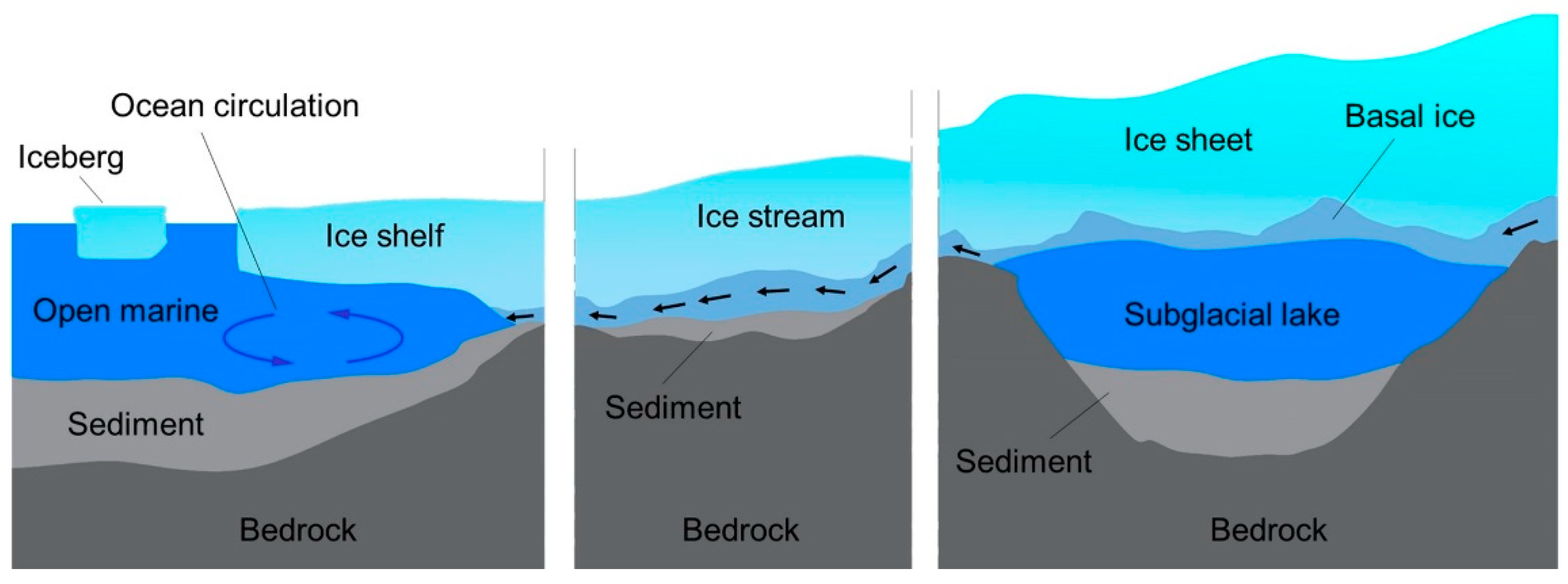
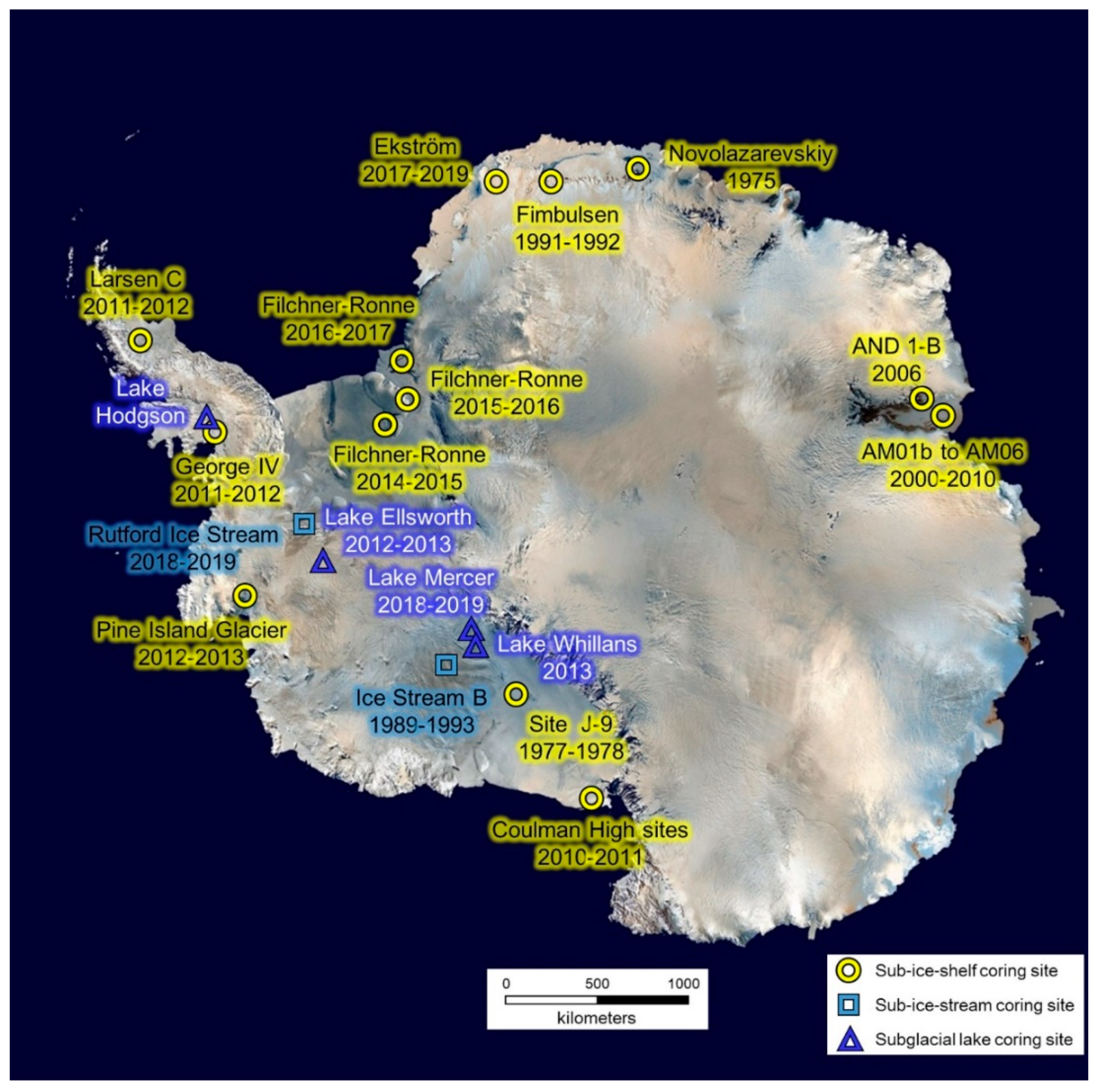
1.1. Where Subglacial Sediments Occur and Detection Methods
1.2. Reasons for the Interest in Coring and Requirements
1.3. Sediment Sampling Restrictions and Difficulties in Subglacial Aquatic Environments
1.3.1. Specific Working Conditions
1.3.2. Surface Operation and Control Facilities
1.3.3. Complicated Sediment Structure
2. Current Subglacial Aquatic Sediment Corers: Method, Working Principle, Design, and Applications
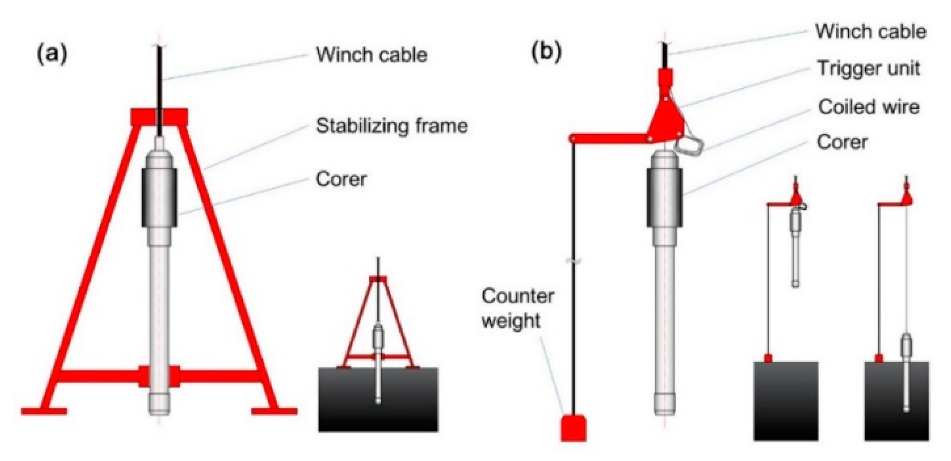
2.1. Gravity and Gravity Piston Corers
2.1.1. ‘Benthos Model 2171′ Gravity Corer
2.1.2. ‘Wintle’ Corer
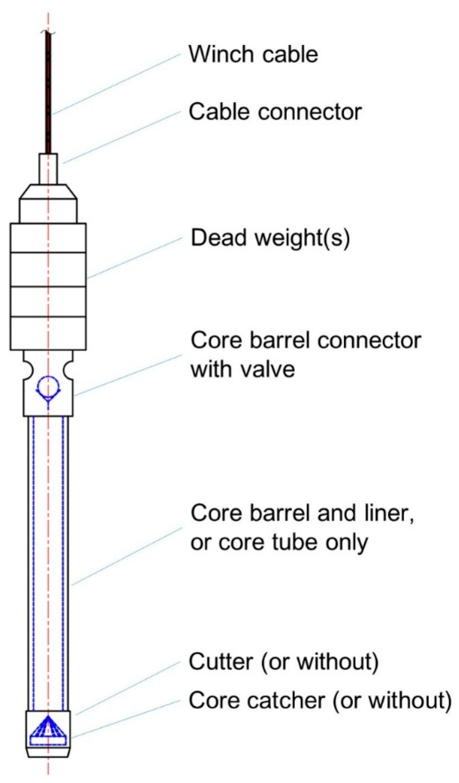
2.1.3. AWI Gravity Corer
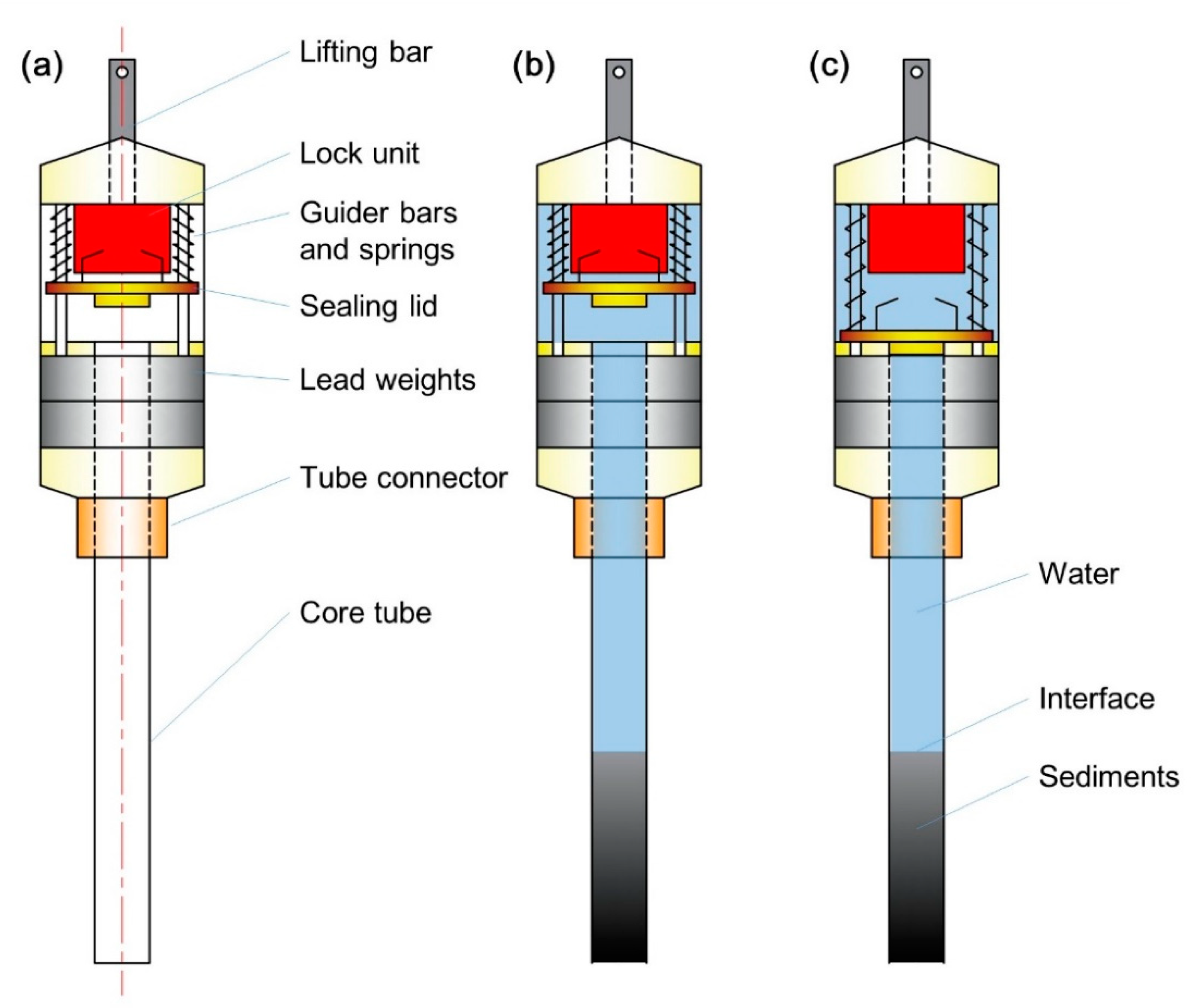
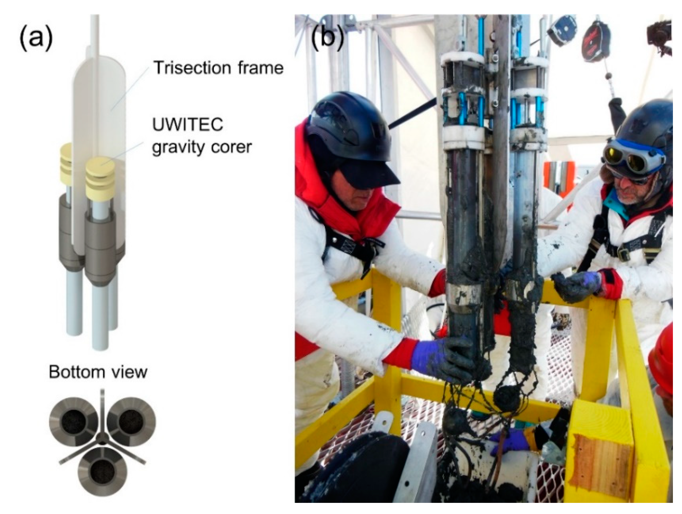
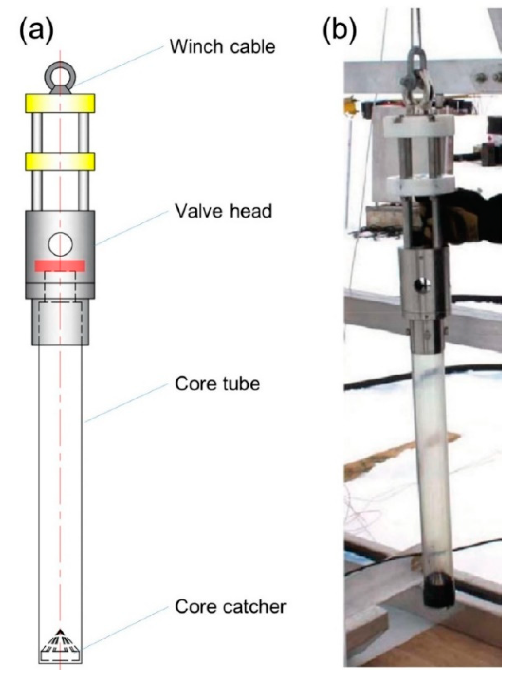
2.1.4. UWITEC Gravity Corer and NIU/UWITEC Multi-Corer
2.1.5. BAS/UWITEC Gravity Corer
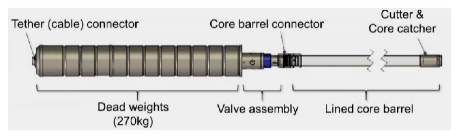
2.1.6. SLE Gravity Corer
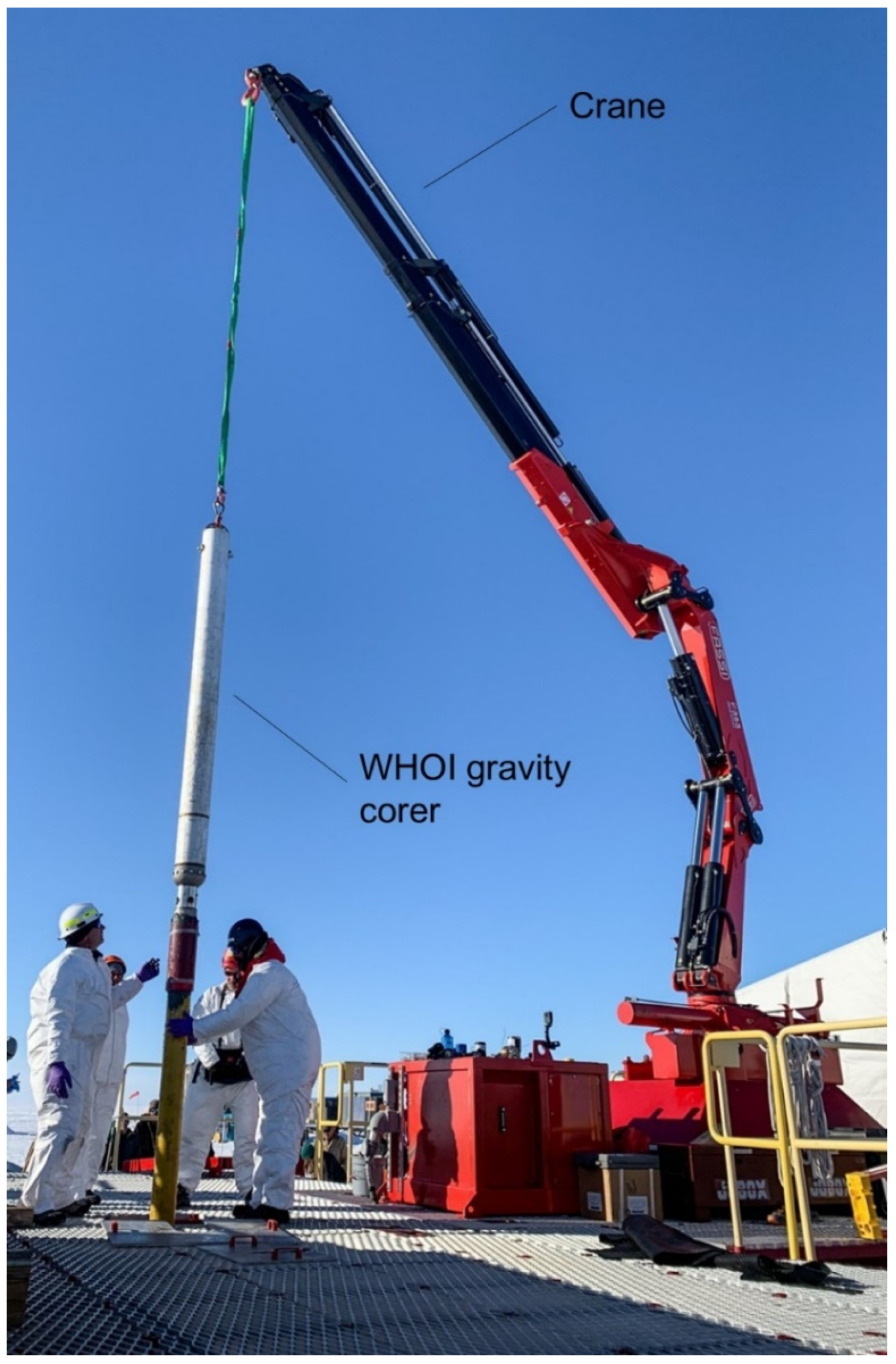
2.1.7. WHOI Gravity Corer
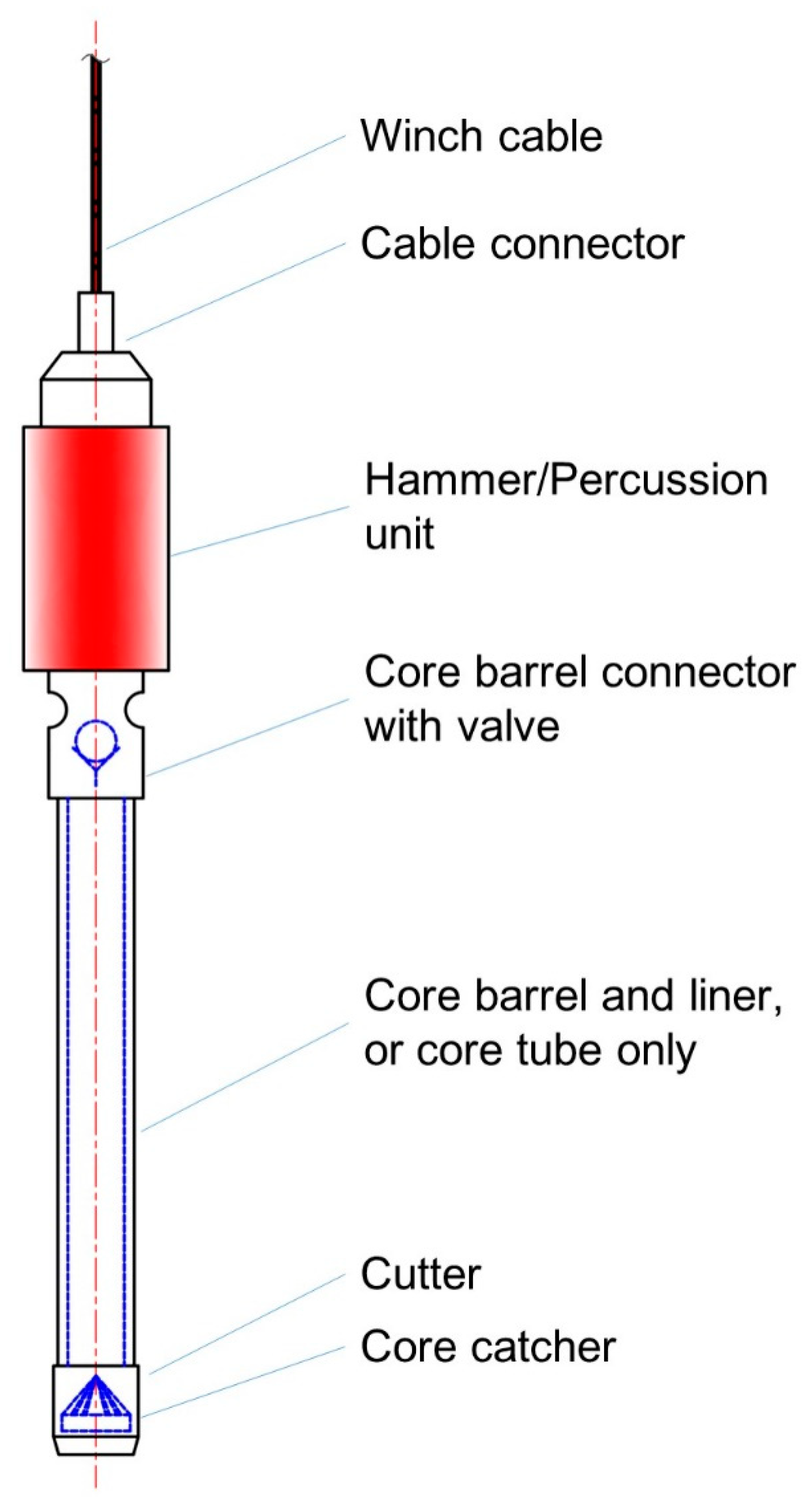
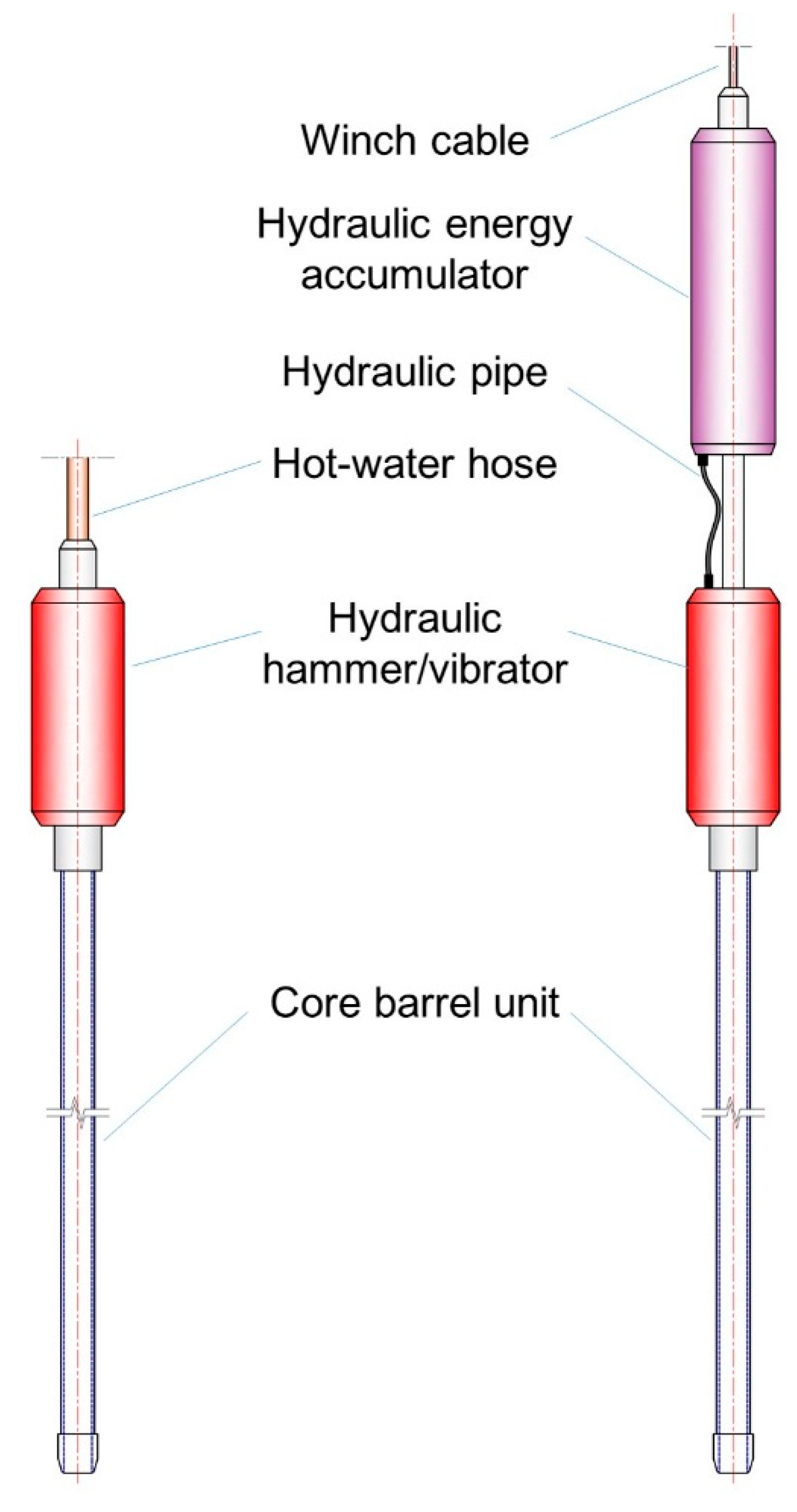
2.2. Hammer/Percussion Corers
2.2.1. BAS/UWITEC and UWITEC Manually Operated Percussion Corer
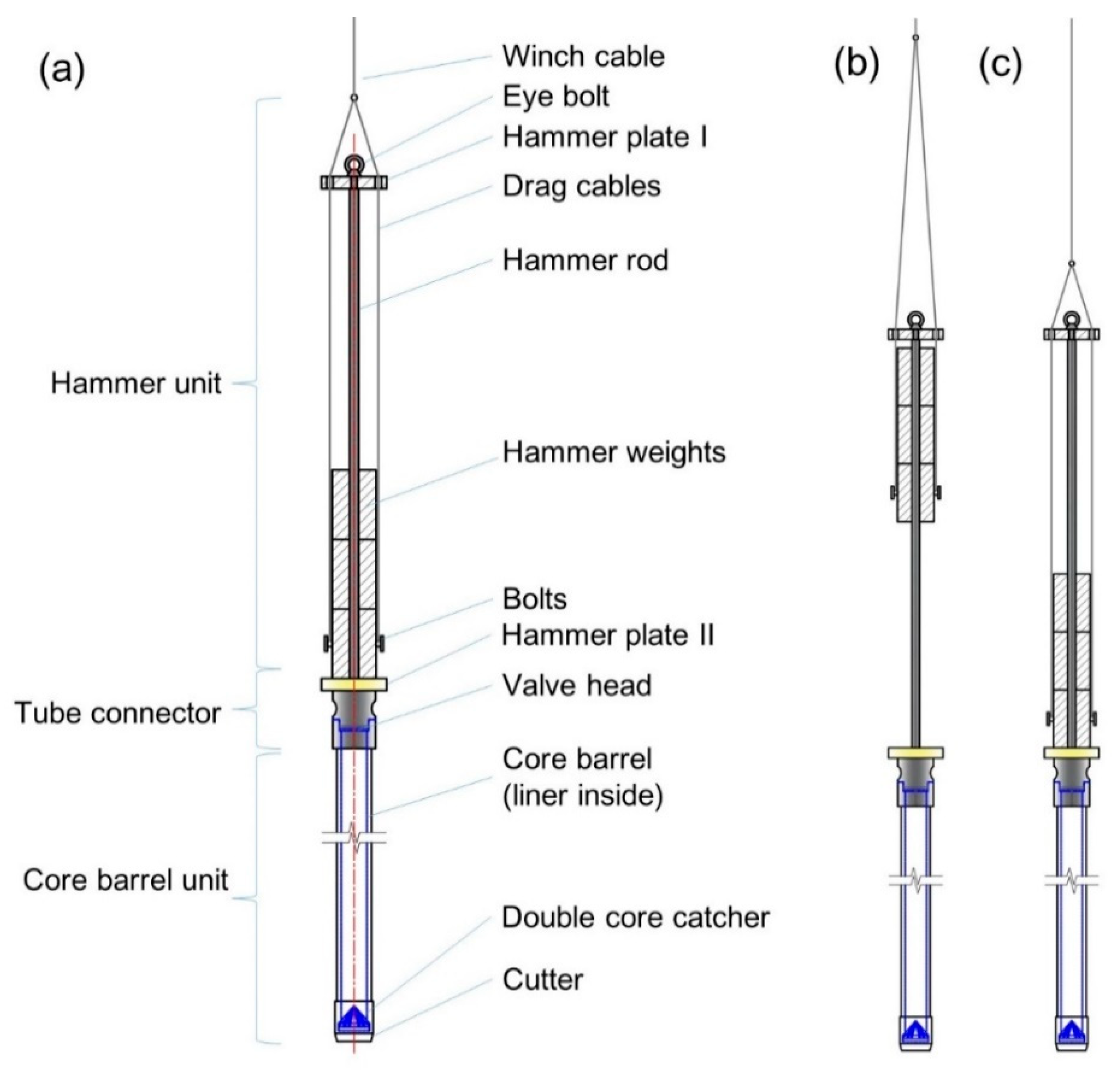
2.2.2. JLU Manually Operated Hammer Corer
2.2.3. NIU Percussion Corer
2.2.4. SLE Percussion Piston Corer
2.3. Piston Corers
2.3.1. Caltech Piston Corer
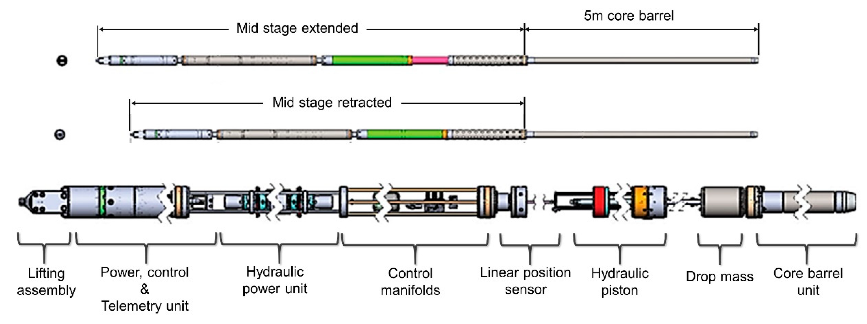
2.3.2. WISSARD/Caltech Piston Corer
2.4. Push Corers and Mini-Corers
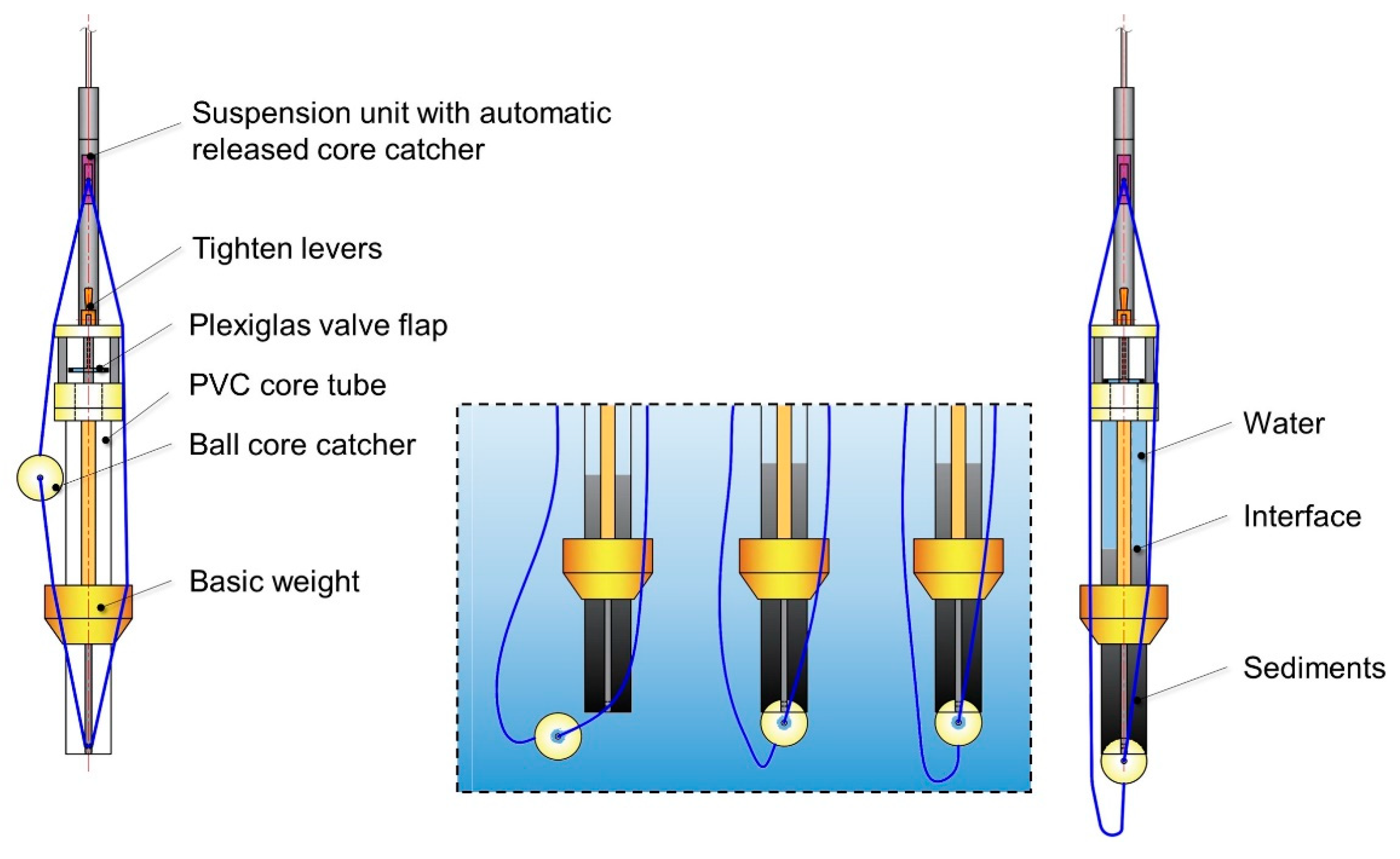
2.4.1. SLE Mini-Push Piston Corer
2.4.2. ANDRILL String Mounted Push Corer
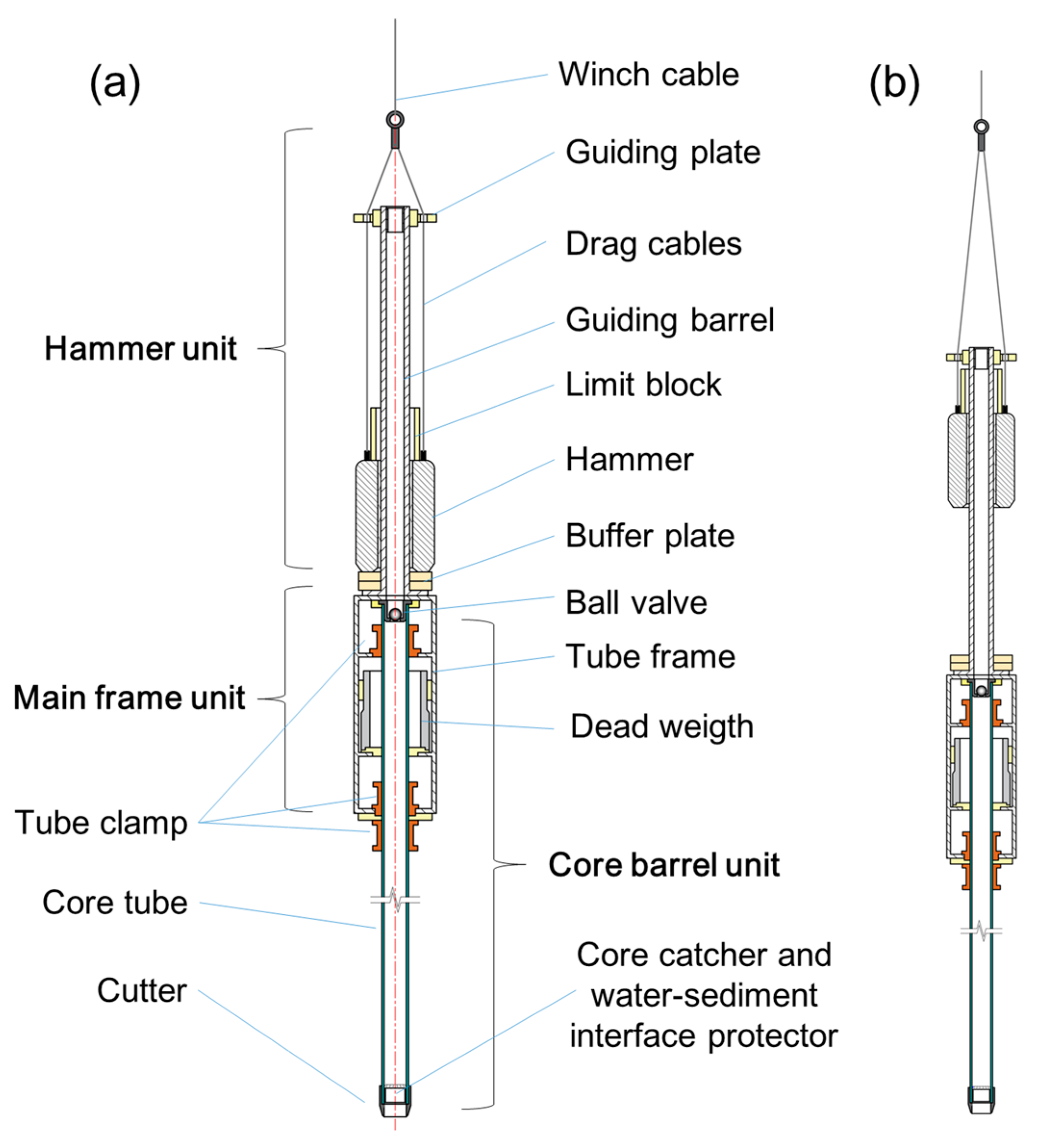
2.5. JLU Self-Synchronous Vibrocorer
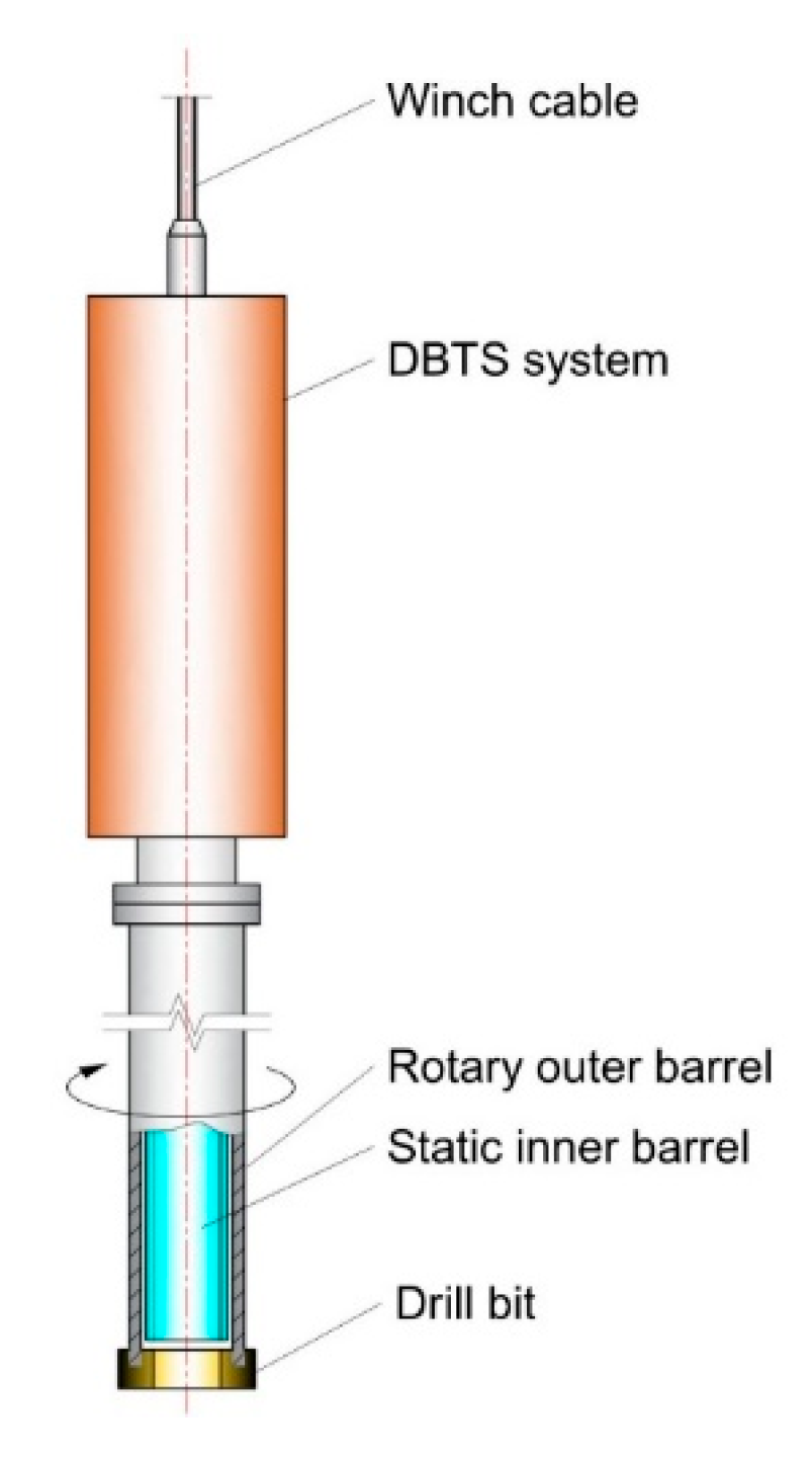
2.6. DBTS Drill (Corer)
2.7. Unidentified Corer
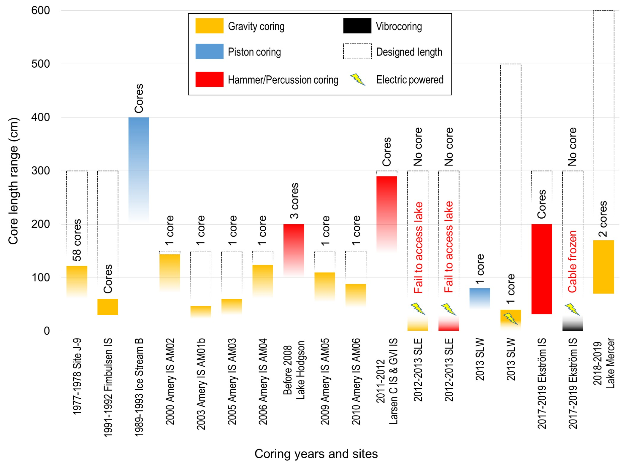
3. General Review of Antarctic Subglacial Aquatic Sediment Coring
3.1. Coring Objectives and Their Respective Coring Methods
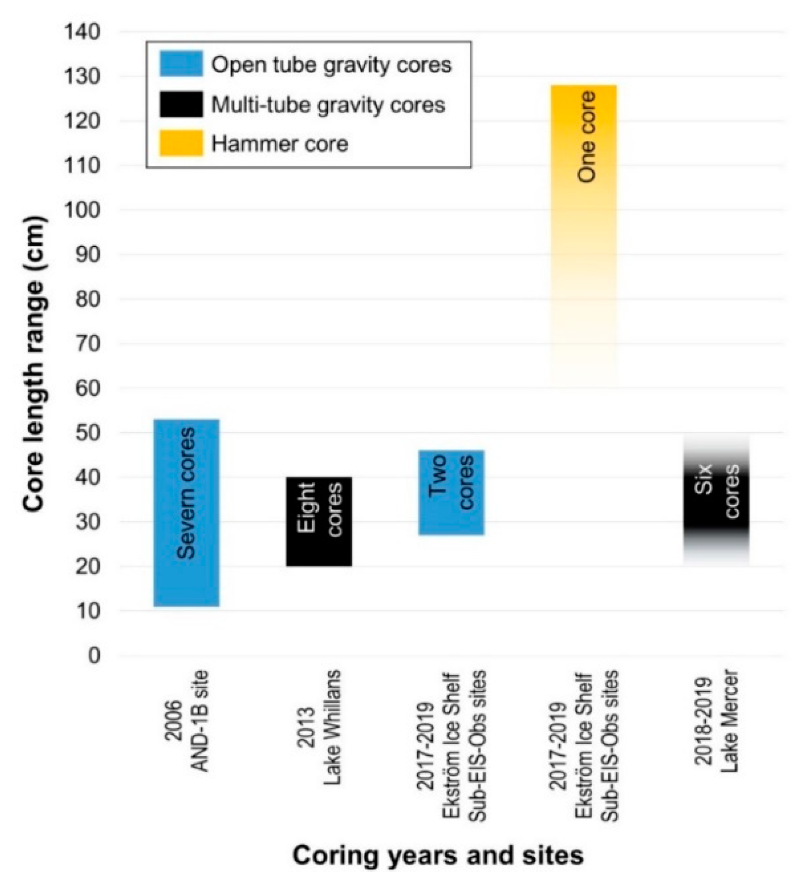
3.1.1. Coring Methods for Obtaining Undisturbed Water–Sediment Interface
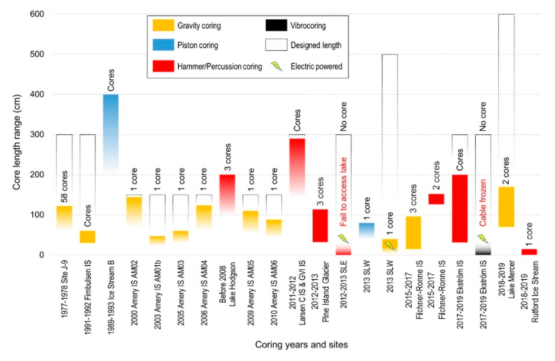
3.1.2. Coring Methods for Obtaining Long Cores
3.2. Discussions
4. Future Prospects
4.1. Methods to Increase Penetration Depth
4.2. Continuous Coring at the Same Position
4.3. Long Core with Undisturbed Water–Sediment Interface
Author Contributions
Funding
Acknowledgments
Conflicts of Interest
References
- Tulaczyk, S.; Mikucki, J.; Siegfried, M. WISSARD at Subglacial Lake Whillans, West Antarctica: Scientific operations and initial observations. Ann. Glaciol. 2014, 55, 51–58. [Google Scholar] [CrossRef]
- Hodson, T.; Powell, R.; Brachfeld, S. Physical processes in Subglacial Lake Whillans, West Antarctica: Inferences from sediment cores. Earth Planet. Sci. Lett. 2016, 444, 56–63. [Google Scholar] [CrossRef]
- Craven, M.; Allison, I.; Brand, R.; Elcheikh, A.; Hunter, J.; Hemer, M.; Donoghue, S. Initial borehole results from the Amery Ice Shelf hot-water drilling project. Ann. Glaciol. 2004, 39, 531–539. [Google Scholar] [CrossRef]
- Lukin, V.; Vasiliev, N. Technological aspects of the final phase of drilling borehole 5G and unsealing Vostok Subglacial Lake, East Antarctica. Ann. Glaciol. 2014, 55, 83–89. [Google Scholar] [CrossRef]
- Christner, B.; Priscu, J.; Achberger, A. A microbial ecosystem beneath the West Antarctic ice sheet. Nature 2014, 512, 310–313. [Google Scholar] [CrossRef] [PubMed]
- Hemer, M.; Harris, P. Sediment core from beneath the Amery Ice Shelf, East Antarctica, suggests mid-Holocene ice-shelf retreat. Geology 2003, 31, 127–130. [Google Scholar] [CrossRef]
- Proposed Exploration of Subglacial Lake Ellsworth Antarctica Final Comprehensive Environmental Evaluation. Available online: https://www.researchgate.net/publication/325114010_Proposed_Exploration_of_Subglacial_Lake_Ellsworth_Antarctica_Final_Comprehensive_Environmental_Evaluation (accessed on 13 May 2019).
- Hodgson, D.; Bentley, M.; Smith, J. Technologies for retrieving sediment cores in Antarctic subglacial settings. Philos. Trans. R. Soc. A Math. Phys. Eng. Sci. 2016, 374, 20150056. [Google Scholar] [CrossRef] [PubMed]
- Mowlem, M.; Saw, K.; Brown, R. Probe technologies for clean sampling and measurement of subglacial lakes. Philos. Trans. R. Soc. A Math. Phys. Eng. Sci. 2015, 374, 20150267. [Google Scholar] [CrossRef][Green Version]
- Post, A.; Galton-Fenzi, B.; Riddle, M. Modern sedimentation, circulation and life beneath the Amery Ice Shelf, East Antarctica. Cont. Shelf Res. 2014, 74, 77–87. [Google Scholar] [CrossRef]
- Talalay, P. Subglacial till and bedrock drilling. Cold Reg. Sci. Technol. 2013, 86, 142–166. [Google Scholar] [CrossRef]
- Smith, A.; Woodward, J.; Ross, N. Evidence for the losng-term sedimentary environment in an Antarctic subglacial lake. Earth Planet. Sci. Lett. 2018, 504, 139–151. [Google Scholar] [CrossRef]
- McKay, R.; Browne, G.; Carter, L. The stratigraphic signature of the late Cenozoic Antarctic Ice Sheets in the Ross Embayment. Geol. Soc. Am. Bull. 2009, 121, 1537–1561. [Google Scholar] [CrossRef]
- Smith, J.; Nicholls, K.; Makinson, K. First Sediment Cores Recovered from Beneath Larsen C and George VI Ice Shelves. In Proceedings of the UK Antarctic Science Conference 2012, British Antarctic Survey, High Cross, Madingley Road, Cambridge, UK, 12–14 September 2012. CB3 0ET. [Google Scholar]
- Carr, S.; Vogel, S.; Dunbar, R. Bacterial abundance and composition in marine sediments beneath the Ross Ice Shelf, Antarctica. Geobiology 2013, 11, 377–395. [Google Scholar] [CrossRef] [PubMed]
- Tulaczyk, S.; Kamb, B.; Scherer, R.; Engelhardt, H. Sedimentary processes at the base of a West Antarctic ice stream; constraints from textural and compositional properties of subglacial debris. J. Sediment. Res. 1998, 68, 487–496. [Google Scholar] [CrossRef]
- Matthew, S.; Oda, R.; Hilde, S. Projected 21st Century Sea-Level Changes, Observed Sea Level Extremes, and Sea Level Allowances for Norway. J. Mar. Sci. Eng. 2017, 5, 36. [Google Scholar] [CrossRef]
- Naish, T.; Powell, R.; Levy, R. Obliquity-paced Pliocene West Antarctic ice sheet oscillations. Nature 2009, 458, 322–328. [Google Scholar] [CrossRef]
- Scherer, R. Pleistocene Collapse of the West Antarctic Ice Sheet. Science 1998, 281, 82–85. [Google Scholar] [CrossRef]
- Thomas, G.; Paulus, P. Biorock Electric Reefs Grow Back Severely Eroded Beaches in Months. J. Mar. Sci. Eng. 2017, 5, 48. [Google Scholar] [CrossRef]
- Siegert, M.; Ross, N.; Le Brocq, A. Recent advances in understanding Antarctic subglacial lakes and hydrology. Philos. Trans. R. Soc. A Math. Phys. Eng. Sci. 2015, 374, 20140306. [Google Scholar] [CrossRef]
- Hodgson, D.; Roberts, S.; Bentley, M. Exploring former subglacial Hodgson Lake, Antarctica. Paper II: Palaeolimnology. Quat. Sci. Rev. 2009, 28, 2310–2325. [Google Scholar] [CrossRef]
- Keen, P.; Saw, K.; Rundle, N. A mini-corer for precision sampling of the water-sediment interface in subglacial lakes and other remote aqueous environments. Limnol. Oceanogr. Methods 2018, 16, 856–867. [Google Scholar] [CrossRef]
- Hughes, K.; Langhorne, P.; Williams, M. Estimates of the refreezing rate in an ice-shelf borehole. J. Glaciol. 2013, 59, 938–948. [Google Scholar] [CrossRef]
- Mowlem, M.; Tsaloglou, M.; Waugh, E. Probe Technology for the Direct Measurement and Sampling of Ellsworth Subglacial Lake. Geophys. Monogr. Ser. 2011, 192, 159–186. [Google Scholar]
- Humphrey, N.; Echelmeyer, K. Hot-water Drilling and Bore-hole Closure in Cold Ice. J. Glaciol. 1990, 36, 287–298. [Google Scholar] [CrossRef]
- Gong, D.; Zhang, N.; Liu, Y.; Li, X.; Talalay, P. Small-diameter vibrocorer for sediment coring beneath Antarctic ice shelves: General concept and testing. Ocean. Eng. 2016, 126, 232–239. [Google Scholar] [CrossRef]
- Gallmetzer, I.; Haselmair, A.; Stachowitsch, M.; Zuschin, M. An innovative piston corer for large-volume sediment samples. Limnol. Oceanogr. Methods 2016, 14, 688–717. [Google Scholar] [CrossRef] [PubMed]
- Chen, J.; Fan, W.; Bingham, B. A Long Gravity-Piston Corer Developed for Seafloor Gas Hydrate Coring Utilizing an In Situ Pressure-Retained Method. Energies 2013, 6, 3353–3372. [Google Scholar] [CrossRef]
- Nikolai, I.; German, L.; Eduard, A. Prospects of Obtaining Samples of Bottom Sediments From Subglacial Lake Vostok. J. Min. Inst. 2017, 244, 199–208. [Google Scholar]
- Siegert, M.; Clarke, R.; Mowlem, M. Clean access, measurement, and sampling of Ellsworth Subglacial Lake: A method for exploring deep Antarctic subglacial lake environments. Rev. Geophys. 2012, 50, 605–606. [Google Scholar] [CrossRef]
- McKay, R.; Barrett, P.; Levy, R. Antarctic Cenozoic climate history from sedimentary records: ANDRILL and beyond. Philos. Trans. R. Soc. A Math. Phys. Eng. Sci. 2015, 374, 20140301. [Google Scholar] [CrossRef]
- Sediment Corers. Available online: http://www.wissard.org/science-and-operations/technology/science-instrumentation/sediment-corers (accessed on 13 May 2019).
- SALSA Borehole Timeline Part 3 of 5: Gravity Corer and Clump Weight Deployment. Available online: https://salsa-antarctica.org/2019/01/21/salsa-borehole-timeline-part-3-of-5-gravity-corer-clump-weight-deployment/ (accessed on 13 May 2019).
- Dunbar, G.B.; Niessen, F.; Vogel, S. Late Pleistocene to Holocene strata from soft-sediment coring at the AND-1B Site, ANDRILL McMurdo Ice Shelf Project, Antarctica. Terra Antarct. 2007, 14, 141–154. [Google Scholar]
- Siegert, M.J.; Behar, A.; Bentley, M. Exploration of Ellsworth Subglacial Lake: A concept paper on the development, organisation and execution of an experiment to explore, measure and sample the environment of a West Antarctic subglacial lake. Rev. Environ. Sci. Biotechnol. 2007, 6, 161–179. [Google Scholar] [CrossRef]
- Maas, S.M. Last Glacial Maximum-Holocene Glacial and Depositional History From Sediment Cores at Coulman High Beneath the Ross Ice Shelf, Antarctica. Master’s Thesis, University of Victoria, Wellington, New Zealand, 2012. [Google Scholar]
- Schimmelmann, J.; Nguyễn-Văn, H.; Nguyễn-Thuỳ, D.; Schimmelmann, A. Low Cost, Lightweight Gravity Coring and Improved Epoxy Impregnation Applied to Laminated Maar Sediment in Vietnam. Geosciences 2018, 8, 176. [Google Scholar] [CrossRef]
- Kolobov, D.D.; Savatyugin, L.M. Bottom sediments under the Novolazarevskiy ice shelf. Polar Geogr. 1982, 6, 267–271. [Google Scholar] [CrossRef]
- Kellogg, D.E.; Kellogg, T.B. Diatom biostratigraphy of sediment cores from beneath the Ross Ice Shelf. Micropaleontology 1986, 32, 74–94. [Google Scholar] [CrossRef]
- Brady, H.T. Interpretation of sediment cores from the Ross Ice Shelf site J-9, Antarctica. Nature 1983, 303, 510–511. [Google Scholar] [CrossRef]
- Clough, J.W.; Hansen, B.L. The Ross Ice Shelf Project. Science 1979, 203, 433–434. [Google Scholar] [CrossRef] [PubMed]
- Østerhus, S.; Orheim, O. Oceanographic and glaciologic investigations through Jutulgryta, Fimbulisen in the 1991/92 season. Norsk Polarinstitutt Meddelelser. 124, 21–28. In Report of the Norwegian Antarctic Research Expedition (NARE); Østerhus, S., Ed.; Norwegian Polar Institute: Tromso, Norway, 1991; Volume 92, pp. 21–28. [Google Scholar]
- Hemer, M.A.; Post, A.L.; O’Brien, P.E. Sedimentological signatures of the sub-Amery Ice Shelf circulation. Antarct. Sci. 2007, 19, 497–506. [Google Scholar] [CrossRef]
- Gromig, R.; Kuhn, G.; Gaedicke, C. Investigating the Seafloor below the Ekström Ice Shelf: The Sub-EIS-Obs Project at East Antarctica’s Continental Margin; EGU2019-8252; EGU General Assembly 2019, Geophysical Research Abstracts; European Geosciences Union: Vienna, Austria, 2019; Volume 21. [Google Scholar]
- Uwitec Sampling Equipments. Available online: http://www.uwitec.at/html/frame.html (accessed on 13 May 2019).
- Hodgson, D.A.; Roberts, S.J.; Bentley, M.J. Exploring former subglacial Hodgson Lake, Antarctica Paper I: Site description, geomorphology and limnology. Quat. Sci. Rev. 2009, 28, 2295–2309. [Google Scholar] [CrossRef]
- Fisher, A.T.; Mankoff, K.D.; Tulaczyk, S.M.; Tyler, S.W.; Foley, N. High geothermal heat flux measured below the West Antarctic Ice Sheet. Sci. Adv. 2015, 1, e1500093. [Google Scholar] [CrossRef]
- WISSARD Updates. 16 January 2015. Available online: http://www.wissard.org/all-wissard-updates (accessed on 13 May 2019).
- Dirt Samples Retrieved From Antarctic Lake Whillans. Available online: http://discovermagazine.com/galleries/2013/jan-feb/antarctic-drilling-samples (accessed on 13 May 2019).
- SALSA Borehole Timeline Part 2 of 5: Sampling, Coring, and CTD Casting. Available online: https://salsa-antarctica.org/2019/01/17/salsa-borehole-timeline-sampling-coring-ctd-casting/ (accessed on 13 May 2019).
- Initial Environmental Evaluation Science Projects on the Filchner-Ronne Ice Shelf, Antarctica. EIAs for Proposed Activities in Antarctica Prepared by the UK. Available online: https://www.bas.ac.uk/wp-content/uploads/2016/11/FISS-IEE-Final-Oct-16.pdf (accessed on 13 May 2019).
- Smith, A.M.; Woodward, J.; Ross, N. Physical Conditions in Subglacial Lake Ellsworth, West Antarctica. In Proceedings of the AGU Fall Meeting, San Francisco, CA, USA, 15–19 December 2008. [Google Scholar]
- Siegert, M.J.; Makinson, K.; Blake, D.; Mowlem, M.; Ross, N. An assessment of deep hot-water drilling as a means to undertake direct measurement and sampling of Antarctic subglacial lakes: Experience and lessons learned from the Lake Ellsworth field season 2012/13. Ann. Glaciol. 2014, 55, 59–73. [Google Scholar] [CrossRef]
- SALSA Celebrates Successful Mission at Mercer Subglacial Lake. Available online: https://salsa-antarctica.org/2019/01/07/salsa-celebrates-successful-mission-at-mercer-subglacial-lake/ (accessed on 13 May 2019).
- Science Team Drills Into Mercer Subglacial Lake. Available online: https://salsa-antarctica.org/2018/12/28/3578/ (accessed on 13 May 2019).
- Makinson, K.; Anker, P.G. The BAS ice-shelf hot-water drill: Design, methods and tools. Ann. Glaciol. 2014, 55, 44–52. [Google Scholar] [CrossRef]
- Smith, J.; Nicholls, K.; Makinson, K. Ice shelf history inferred from sub-ice shelf sediment cores. In Proceedings of the EGU General Assembly Conference Abstracts, Vienna, Austria, 7–12 April 2013; Volume 15. [Google Scholar]
- Smith, J.; Shortt, M.; Bindschadler, B. A PIG Unknown: The First Sediment Cores Recovered from Beneath. Available online: https://www.waisworkshop.org/sites/waisworkshop.org/files/files/agendas/2013/abstracts/Smith_J.pdf (accessed on 15 June 2019).
- Smith, J.; Andersen, M.; Gaffney, A. Sub-ice-shelf sediments record history of twentieth-century retreat of Pine Island Glacier. Nature 2016, 541, 77–80. [Google Scholar] [CrossRef] [PubMed]
- UK Team Drills Record West Antarctic Hole. Available online: https://www.bbc.com/news/science-environment-46978496 (accessed on 15 June 2019).
- Harms, U.; Mingram, J.; Brademann, B. Probengewinnung in Lockersedimenten. System 2014, 4, 54–59. [Google Scholar] [CrossRef]
- Antarctic Photo Library. Available online: https://photolibrary.usap.gov/PhotoDetails.aspx?filename=WISSARD-antarctica-subglacial-lake-whillans-Percussion-Core-recovery.jpg (accessed on 15 June 2019).
- McGinnis, T. Seafloor Drilling. In Drilling in Extreme Environments: Penetration and Sampling on Earth and Other Planets; Bar-Cohen, Y., Zacny, K., Eds.; John Wiley & Sons: Hoboken, NJ, USA, 2009; pp. 309–346. [Google Scholar]
- Qin, H.W.; Chen, Y.; Gu, L.Y. Research on disturbing theory of deep-sea sediment sampling. Acta Oceanol. Sin. 2007, 29, 92–97. [Google Scholar]
- Skilbeck, C.G.; Trevathan-Tackett, S.; Apichanangkool, P.; Macreadie, P.I. Sediment sampling in estuaries: Site selection and sampling techniques. In Applications of Paleoenvironmental Techniques in Estuarine Studies; Springer: Dordrecht, The Netherlands, 2017; pp. 89–120. [Google Scholar]
- Filina, I.Y.; Blankenship, D.D.; Thoma, M. New 3D bathymetry and sediment distribution in Lake Vostok: Implication for pre-glacial origin and numerical modeling of the internal processes within the lake. Earth Planet. Sci. Lett. 2008, 276, 106–114. [Google Scholar] [CrossRef]
- Romano, E.; Bergamin, L.; Magno, M.C. Differences in acquisition of environmental data in strongly impacted marine sediments using gravity and vibro corers: The case-study of Augusta harbor (Eastern Sicily, Italy). Measurement 2018, 124, 184–190. [Google Scholar] [CrossRef]
- Ross, N.; Siegert, M.J.; Rivera, A. Ellsworth Subglacial Lake, West Antarctica: A review of its history and recent field campaigns. Antarct. Subglacial Aquat. Environ. 2011, 192, 221–233. [Google Scholar]
- Burns, R.E. Free-fall behavior of small, light-weight gravity corers. Mar. Geol. 1966, 4, 1–9. [Google Scholar] [CrossRef]
- Kristoffersen, Y.; Lien, E.; Festervoll, K. The hydrostatic corer Selcore—A tool for sediment sampling and geophysical site characterization. Mar. Geol. 2006, 229, 101–112. [Google Scholar] [CrossRef]
- Wang, J.; Qin, H.; Chen, Y. Analysis and modeling of the percussion coring of an innovative hydrostatic sediment corer. Ocean. Eng. 2017, 134, 87–95. [Google Scholar] [CrossRef]
- Lunne, T.; Long, M. Review of long seabed samplers and criteria for new sampler design. Mar. Geol. 2006, 226, 145–165. [Google Scholar] [CrossRef]
- Yang, J.; Liu, Y.; Ye, Z.; Yang, D.; He, S. A study of friction and wear behavior of nitrided layer on 2cr13 steel in vacuum. Tribol. Lett. 2010, 40, 285–294. [Google Scholar] [CrossRef]
- Babu, P.S.; Rao, D.S.; Krishna, L.R.; Sundararajan, G. Weibull analysis of hardness distribution in detonation sprayed nano-structured WC-12Co coatings. Surf. Coat. Technol. 2017, 319, 394–402. [Google Scholar] [CrossRef]
- Kovaleva, M.; Tyurin, Y.; Kolisnichenko, O.; Prozorova, M.; Arseenko, M. Properties of detonation nanostructured titanium-based coatings. J. Therm. Spray Technol. 2013, 22, 518–524. [Google Scholar] [CrossRef]
- Paikowsky, S.G.; Whitman, R.V. The effects of plugging on pile performance and design. Can. Geotech. J. 1990, 27, 429–440. [Google Scholar] [CrossRef]
- Xu, L.; Karunakaran, R.G.; Guo, J.; Yang, S. Transparent, superhydrophobic surfaces from one-step spin coating of hydrophobic nanoparticles. ACS Appl. Mater. Interfaces 2012, 4, 1118–1125. [Google Scholar] [CrossRef] [PubMed]
- Saltuganov, P.N.; Ionin, A.A.; Kudryashov, S.I. Fabrication of superhydrophobic coating on stainless steel surface by femtosecond laser texturing and chemisorption of an hydrophobic agent. J. Russ. Laser Res. 2015, 36, 81–85. [Google Scholar] [CrossRef]


| Year and References | Location | Corer Name & Type | Project or Unit | Core Length (cm) | Ice Thickness (m) | Water Depth (m) | Distance between Ice Surface to Sediment (m) | Coring Characteristic Items |
|---|---|---|---|---|---|---|---|---|
| 1975 [40] | Novolazarevskiy ice shelf | - | 20th Soviet Antarctic expedition | 28 | 357 | 203 | - | - |
| 1977–1978 [41] | Ross ice shelf | Benthos model 2171 | RISP | 58 cores: up to 122 | 420 | 237 | 597 | (1) Flame-jet drilling access borehole size 30–80 cm (2) 3 m long core barrel |
| Site J-9 | GC | |||||||
| 1991–1992 [8] | Fimbulsen Ice Shelf | Benthos model 2171 GC | NARE | Cores: 30 to 60 | - | 400 | - | (1) Corer total weight 110 kg. (2) 2.4 m long in corer liner with ID 67 mm |
| 1989–1993 [16,19] | Ice Stream B | Caltech | - | Cores: up to 400 | ~1030 | ~600 | - | (1) 6 m in corer length and liner ID 50 mm (2) 10 cm diameter borehole |
| (UpB camp area) | PC | |||||||
| 2000 [10] | Amery Ice shelf AM02 | Wintle GC | AMISOR | 144 | 373 | - | 843 | (1) ~40cm diameter hot-water access borehole. (2) Purpose-built slim-line, 12 cm diameter gravity corer |
| 2003 [10] | Amery Ice shelf AM01b | 47 | 479 | - | 840 | |||
| 2005 [10] | Amery Ice shelf AM03 | 60 | 722 | - | 1339 | |||
| 2006 [10] | Amery Ice shelf AM04 | 124 | 603 | - | 1002 | |||
| 2006 [35] | McMurdo ice shelf AND-1B site | AWI GC | ANDRILL | Seven WSI cores: 11 to 53 | 82 | 850 | - | (1) 80 kg weight with 5–22 m release distance (2) Equipped with plastic core tube 1.0 or 1.5 m in length and 59.5/63 mm in ID/OD (3) Open tube end |
| ANDRILL PushC | Four cores: 33 to 156 | (1) PQ drill string installed (2) 73 kPa shear strength at 1.94 m sediment depth | ||||||
| Before 2008 [8,9] | Hodgson Lake | UWITEC | BAS | - | 3.7 | - | 93.4 | (1) Surface sediments collected (2) Automatic ball valve core catcher |
| GC | ||||||||
| UWITEC KOL Kolbenlot PerC | 3 cores up to 200 | Three 2 m cores with total penetration depth 3.76 m | ||||||
| 2009 [10] | Amery Ice shelf AM05 | Wintle GC | AMISOR | 110 | 624 | - | 979 | ~40 cm diameter hot-water access borehole. |
| 2010 [10] | Amery Ice shelf AM06 | 88 | 607 | - | 902 | |||
| 2010–2011 [38] | Ross Ice Shelf Coulman High | AWI | ANDRILL | 28 cores, up to 129 | Four sites: 261 to 268 | Four sites: 798 to 864 | - | (1) Equipped with 0.5–2 m long plastic core barrel (2) 5 to 20 m ‘free fall’ distance |
| GC | ||||||||
| 2011–2012 [58] | Larsen C Ice Shelf & southern GVI-IS | BAS MO-PercC | BAS | TL 1160 up to 290 | - | - | - | - |
| 2012–2013 | Pine Island Glacier PIG A. PIG B, PIG C | BAS MO-PercC | BAS | 30, 92, 115 | ~500 to 600 | WCT ~200 to 400 | - | (1) 20 cm diameter hot-water access borehole (2) Type of sediment: mud, sandy mud, gravelly–sandy mud or muddy gravel (3) grain size up to 8 mm |
| 2012–2013 [7,8,23,33] | Lake Ellsworth (~36 cm ID access borehole, un-accessed lake) | SLE GC | SLE | - | ~3000 | WCT ~150 | - | (1) 270kg with 3.7m core tube (2) With cutter and core catcher |
| SLE BAS/UWITEC CEP-PercC | ||||||||
| - | - | (1) Real-time camera monitoring coring (2) Linear motors powered hammer | ||||||
| SLE CEP- PushC | - | - | (1) Real-time camera monitoring coring (2) Push coring and ball valve sealing by single drive (3) Volume compensation piston | |||||
| 2013 [1,8,63] | Lake Whillans (min 60 cm ID access borehole) | NIU/UWITEC Multi-GC | WISSARD | WSI 8 cores 20 to 40 | 797 ± 10 | 724.6 ± 0.7 | 802.6 ± 0.8 | (1) Three replicated cores can be obtained once together (2) Automatic ball valve core catcher (3) Seven unsuccessful attempts due to corer radial size |
| WISSARD/Caltech PC | 80 | (1) Wireline messenger trigger released (2) Guiding plates on top end | ||||||
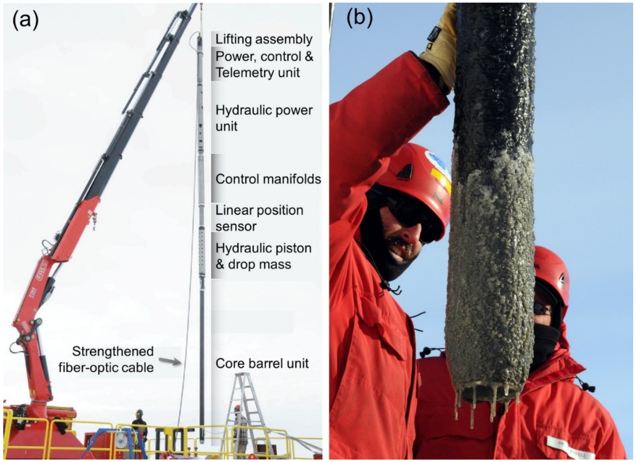
| 2013 [1,8,63] | Lake Whillans (min 60 cm ID access borehole) | NIU CEP-PercC | WISSARD | 40 | 797 ± 10 | 724.6 ± 0.7 | 802.6 ± 0.8 | (1) Automatic ~900 kg hydraulic percussion drop mass (2) ~14 m corer length, 5 m core barrel with ID/OD 100/141 mm (3) smart winch error resulted in worked as a gravity corer |
| 2014–2015 [52] | Filchner-Ronne Ice Shelf S5A, S5B, S5C | BAS/UWITEC GC | BAS | Seven cores: TL 265 | ~770 | WCT | - | (1) 30 cm hot water access borehole (2) Equipped with cutter and core catcher |
| ~400 | ||||||||
| 2015–2016 [52] | Filchner-Ronne Ice Shelf FSW1 | BAS/UWITEC GC | 33 | 853 | WCT | - | (1) 3 m long cores were expected (2) 30 cm hot water access borehole (3) GC with cutter and core catcher | |
| BAS Mini-C | 14 | 471 | - | |||||
| Filchner-Ronne Ice Shelf FSE1 | BAS/UWITEC GC | 8 | 891 | WCT | - | |||
| BAS Mini-C | 73, 78 | 528 | - | |||||
| Filchner-Ronne Ice Shelf FSE2 | BAS/UWITEC GC | 55 | 837 | WCT | - | |||
| BAS Mini-C | 36 | 442 | - | |||||
| 2016–2017 | Filchner-Ronne Ice Shelf FNE1 | BAS Mini-C | BAS | 64 | 615 | 440 | - | - |
| Filchner-Ronne Ice Shelf FNE2 | BAS MO-PercC | 135.5 | 597 | 588 | - | |||
| BAS Mini-C | 75.5 | - | ||||||
| Filchner-Ronne Ice Shelf FNE3 | BAS MO-PercC | 152 | 597 | 643 | - | |||
| BAS Mini-C | 75.5 | - | ||||||
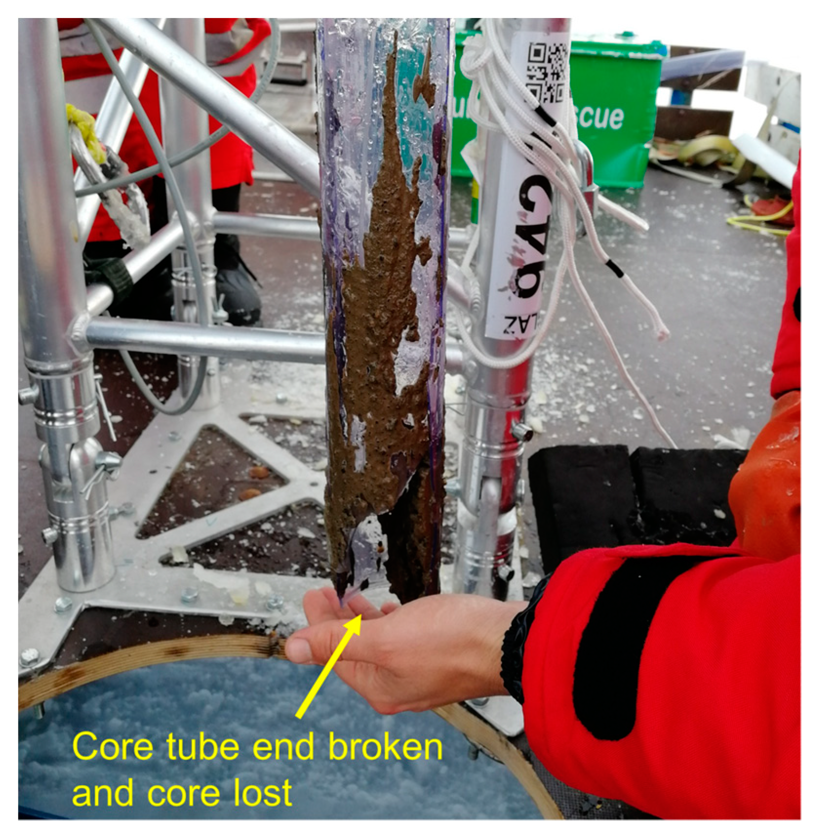
| 2017–2019 (unpublished data) | Ekström Ice Shelf Neumayer Station III | AWI GC | AWI | WSI cores: up to ~46 | 187 to 332 | 118 to 656 | ~270 to 700 | (1) un-functioned valve caused more than half GC runs without core (2) 5 to 15 m release distance (3) Core tube end broken in some runs |
| 2017–2019 (unpublished data) | Ekström Ice Shelf Neumayer Station III | BAS/UWITEC MO-PercC | AWI | Cores: 32 to 200 | 187 to 332 | 118 to 656 | ~270 to 700 | (1) Corer max OD 140 mm, 3 m core barrel (2) 3 hammer weights together ~33 kg |
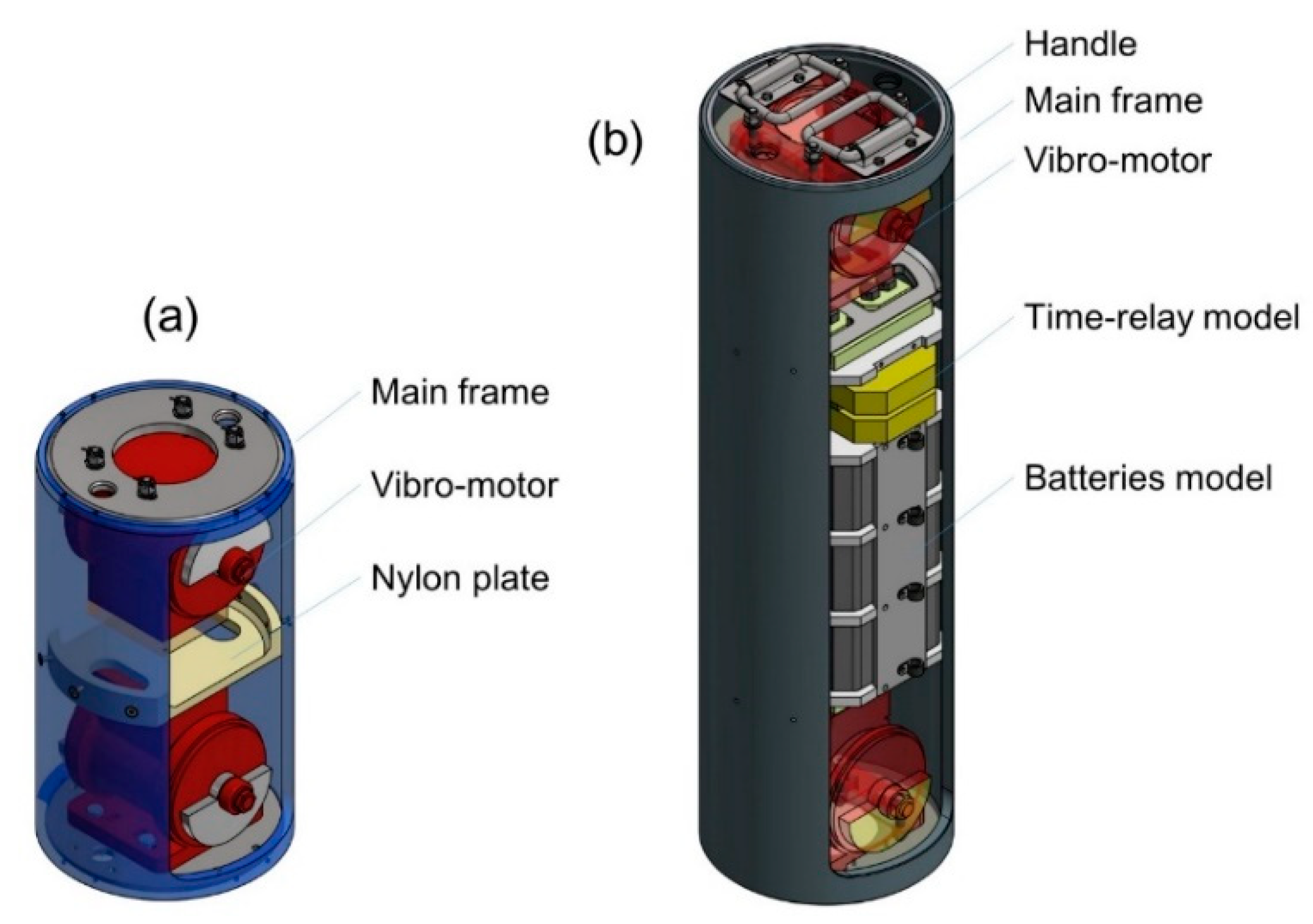
| JLU VC | - | (1) 270 mm max OD, 256 kg, 50 Hz self-synchronous vibro-head (2) Self-contained batteries with time-delay power-on | ||||||
| JLU VC+ | - | (1) Cut core barrel cross-section to 50% (2) Time-delay power-on with intermittent vibration mode (3) Standard Makita batteries | ||||||
| JLU MO-HC | WSI 128 | (1) Tube only with cutter, core catcher and ball valve (2) Long core with well-preserved water–sediment interface (3) 38 kg hammer | ||||||
| 2018–2019 | Rutford Ice Stream | BAS MO-PercC | BAS | ~10 | 2152 | - | - | The deepest hot water drilled subglacial access borehole |
| 2018–2019 [56,57] | Lake Mercer | NIU/UWITEC Multi-GC | SALSA | Six cores with WSI | - | 15 | 1084 | (1) ~60 cm diameter access borehole (2) At least 6 cores with water–sediment interface obtained |
| WHOI GC | 70, 170 | 9.1 m in corer length and 6 m core barrel |
© 2019 by the authors. Licensee MDPI, Basel, Switzerland. This article is an open access article distributed under the terms and conditions of the Creative Commons Attribution (CC BY) license (http://creativecommons.org/licenses/by/4.0/).
Share and Cite
Gong, D.; Fan, X.; Li, Y.; Li, B.; Zhang, N.; Gromig, R.; Smith, E.C.; Dummann, W.; Berger, S.; Eisen, O.; et al. Coring of Antarctic Subglacial Sediments. J. Mar. Sci. Eng. 2019, 7, 194. https://doi.org/10.3390/jmse7060194
Gong D, Fan X, Li Y, Li B, Zhang N, Gromig R, Smith EC, Dummann W, Berger S, Eisen O, et al. Coring of Antarctic Subglacial Sediments. Journal of Marine Science and Engineering. 2019; 7(6):194. https://doi.org/10.3390/jmse7060194
Chicago/Turabian StyleGong, Da, Xiaopeng Fan, Yazhou Li, Bing Li, Nan Zhang, Raphael Gromig, Emma C. Smith, Wolf Dummann, Sophie Berger, Olaf Eisen, and et al. 2019. "Coring of Antarctic Subglacial Sediments" Journal of Marine Science and Engineering 7, no. 6: 194. https://doi.org/10.3390/jmse7060194
APA StyleGong, D., Fan, X., Li, Y., Li, B., Zhang, N., Gromig, R., Smith, E. C., Dummann, W., Berger, S., Eisen, O., Tell, J., Biskaborn, B. K., Koglin, N., Wilhelms, F., Broy, B., Liu, Y., Yang, Y., Li, X., Liu, A., & Talalay, P. (2019). Coring of Antarctic Subglacial Sediments. Journal of Marine Science and Engineering, 7(6), 194. https://doi.org/10.3390/jmse7060194