1. Introduction
Transportation has been playing an important role in human society, and industrial development since the first industrial revolution took place more than two centuries ago. It started with the use of the animal as the driving force followed by the application of diesel engine in inland, aerospace, and water transportation. Furthermore, human interaction also experiences massive progress, for example, the use of a mobile phone makes it more convenient to communicate over long distances compared to the conventional methods of communication. This was followed by the evolution of these phones to become smart leading to easy business transactions, trading and several other forms of interaction. For the purpose of this study, transportation mode is focused because it requires carrying subjects from one location to the other based on designated missions, for example, it is possible to transport humans and commodities using a public vehicle which is classified as an inland transportation mode. However, most archipelago countries are faced with the challenges of obtaining another transportation mode to transport people on the island and this led to the use of water transportation mode by the public, thereby, making it become one of the highest maritime business potentials in these countries. Consequently, roll on-roll off (Ro-Ro) ship was considered the most suitable vessel in this situation due to its capability to convey a large number of vehicles, passengers, and commodities at the same time to cross the sea or strait.
The Ro-Ro ship is a vessel with the cargo wheeled or loaded/unloaded on board, in a vehicle or other platforms equipped with wheels. The first ships to be classified under this category were the Ferry equipped with railways to allow the transport of train carriages between the margins of the rivers considered too wide for bridges. The use of the Ro-Ro concept in merchant ships started in the late 1940s, early 1950’s and mainly in the short-sea routes, such as inter-island route through the strait in archipelago countries. It became a significant vital transportation mode and a traffic connector. Furthermore,
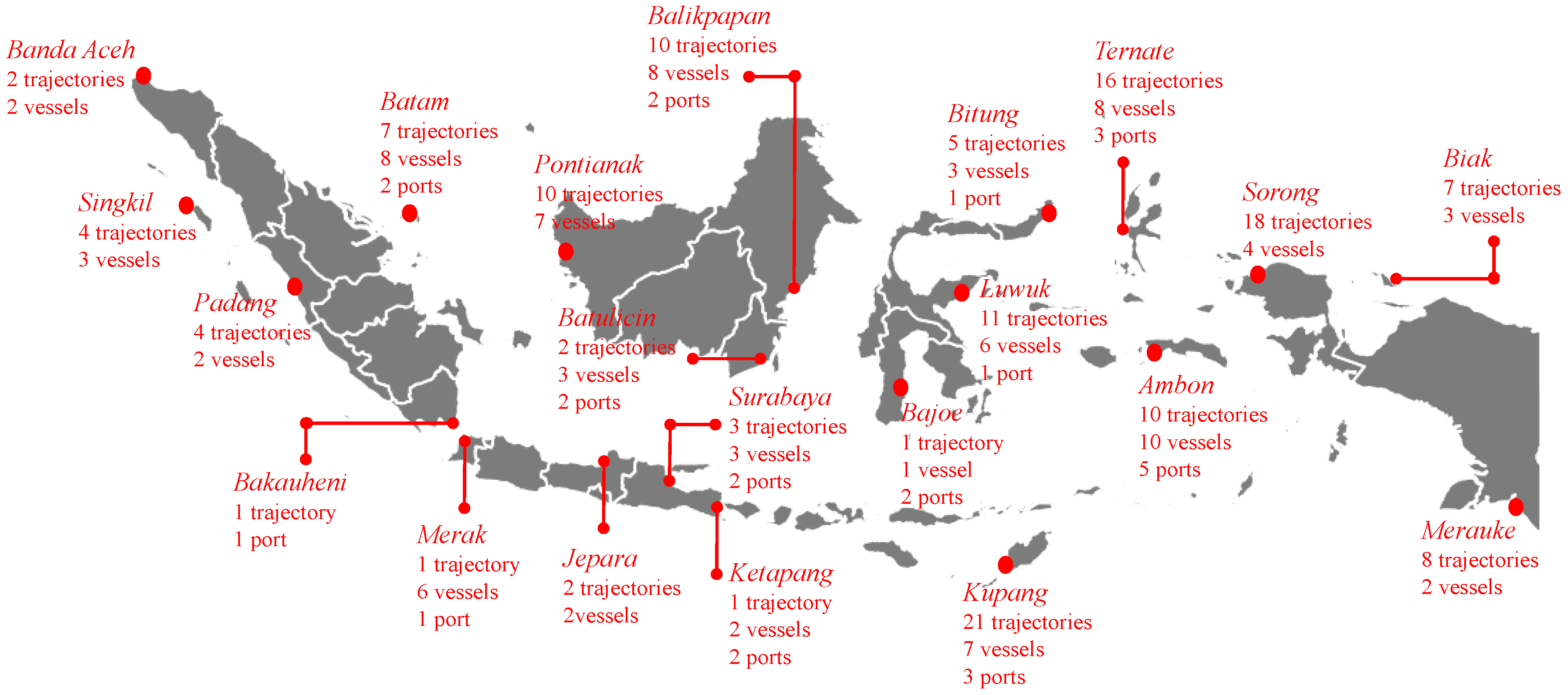
Figure 1 shows how the infrastructures for Ro-Ro spread on the islands of Indonesia thereby making domestic water traffic of the country to be very high. This is also influenced by the use of the strait between the islands as international route, especially from East Asian countries such as South Korea, Japan and China and Southeast Asia including Singapore to reach Australia [
1,
2,
3].
With due consideration for the traffic situation of archipelago countries through the use of Indonesia as a representative, it is mandatory to ensure ship safety during daily operation. However, the most serious threat was observed to be the possible occurrence of impact load due to several causes, and the data recently released by Allianz [
5] indicated collision and grounding to be the most frequent. The high number of casualties as a result of these usually vary, but they are all usually triggered by the structural rupture of the load [
6,
7,
8,
9], and this makes it important to conduct an analysis on the subject. Therefore, the objective of this study was to investigate the collision phenomenon of impact load involving two ships using a numerical approach, i.e., nonlinear finite element method (NLFEM). This method was considered suitable for this case since the analytical method is limited in term of material aspect and structural complexity and because the idealized phenomena were in large scale involving several parameters. Furthermore, the comparison of the structural parameters based on the NLFEM analysis was discussed as a contact scenario is designed by varying collision angle.
2. Literature Reviews: Ro-Ro and Maritime Incidents
The first time Ro-Ro was introduced to the public, it was intended to transport train carriages between the margins of the rivers considered too wide for bridges in Scotland and, for its effective operation, the vessel was equipped with railways. However, the war experienced across the European continent affected the rapid development of technology, water transportation inclusive. Moreover, the World War II motivated the improvement of Ro-Ro vessel to be more adaptable as landing vessel for military equipment and this is presently being used for both military and offshore industries as the Landing Craft Tank (LCT). After the war, the previously modified Ro-Ro was converted for other operation schemes like merchant ship MV Virginia Beach. Furthermore, in order to fulfill several objectives in maritime industries, Ro-Ro vessel was modified to provide several other types such as:
Ro-Ro passenger (Ro-Pax)
It has a large deck, and limited passenger facilities (less than passenger ferries) and its superstructures cover part of the deck.
Pure car carriers
It is designed for only one purpose, which is to efficiently transport cars or other types of vehicles such as bus, truck, etc. According to Wärtsillä, the largest deep-sea car carriers in service has the ability to convey up to 8000 car equivalent units [
10].
Lift on-lift off (Lo-Lo)
This is similar to freight, but it has a different mechanism compared to general container vessel. The container vessel usually performed their loading and unloading with a port/harbor facility, while Lo-Lo conducts the process with the use of an onboard crane.
Identification of loss and risk during a vessel operation is very important in maritime industries, especially to a company’s financial and insurance policy and misconduct in this aspect has the ability to lead a company to bankruptcy due to the occurrence of certain accidents in the fleet. This phenomenon is rising as several accidents in the maritime environment have been proved to be an initial trigger for massive losses such as iceberg-ship impact case of the Titanic [
11], large scale oil spill accident of the Sea Empress [
12], death toll in the Sewol’s sinking [
13], environmental destruction and species extinction after the Exxon Valdez ran aground and spilled oil [
14], Halifax explosion accident in Canada with death estimation reached 2000 people [
15,
16], and massive financial loss for passenger compensation, ship evacuation and environment restoration in grounding case of the Costa Concordia [
17]. From all these, collision and grounding appear to be the highest cause of vessel losses in the category of accidental loads.
Furthermore, from a calculated data of 2018, Allianz [
18] showed 90% of global trades/commodities are transported by shipping, and this reflects the contributions of several types of ships to the sustainability of global economy and growth. However, despite its positive value, there are several challenges in its operations.
Table 1 and
Table 2 shows the number of total loses per region from 2008–2017, and Southeast Asia region holds the largest spot, exceeding the East Mediterranean and the Black Sea. Advance assessment in 2017 also pointed out accidental loading was the main cause of largest ships lost as shown in
Table 3, with three out of ten largest cases found in Indonesia and Philippines, and observed to have involved bulk carrier and passenger vessels.
3. Pioneer Work Related to Impact Loading in the Maritime Environment
The efforts are classified into active and passive major groups as introduced by Törnqvist [
19] and Prabowo [
20]. The active group is conducting research to support ships during their operations and interactions with other facility and infrastructure in order to avoid accidental phenomena. The navigation system is one the popular field in this group and series of researches are dedicated to improve and expand the capability of radar, communication instrument, gyrocompass, etc, such as the works conducted by Perera and Mo [
21], Yoo [
22] and An [
23]. On the contrary, the passive group focuses on the assessment of structural performance during and after accidents, and the prediction of casualties/loss on the involved parties. However, this work was considered a fundamental aspect in developing marine technology as the results of the assessment and prediction in this group are adopted as reference data for the active group to improve navigation as well as mitigation for ship and other marine structures. Several scholars such as Amdahl [
24], Soares [
25], Pedersen [
26] and Prabowo [
27] concentrated their research in this field with varieties of researches, as many as the active group. The main motive of these works was to understand the accidental load/event, such as the reoccurrence of collision, grounding, and explosion despite the achievement of major progress of navigational instruments.
Furthermore, this group was mainly analyzed through the use of numerical analysis (FEM), analytical formula, and empirical approach. The FEM is considered the most developed method compared to others in terms of size, large scale structure, proper ship modeling including the boundary condition, and loading scheme. Moreover, in terms of the considered parameter, more aspects are inputted into the model to idealize the complexity of an accidental model in very specific details. With respect to the works previously mentioned, the analytical formula and empirical approach are currently considered in the analysis as comparison and validation of the numerical calculation. Similarly, the main motive of this analysis form is that both methods referred to pioneer experimental test with better accuracy as the phenomena were physically investigated.
4. Analysis Preparation and Modelling Configuration
4.1. Vessel Geometry
Two vessels were used in this study with the Ro-Ro used as the struck vessel and cargo as the striking vessel as shown in
Figure 2. The struck ship was idealized as a deformable body with an inner structural arrangement such as inner shell, frame, and girder. On the contrary, the striking vessel was defined as a rigid body modelled on bow geometry without inner structure. These assumptions were implemented to focus the damage observation on the struck vessel. Furthermore, by deploying a rigid striking vessel, the worst damage was estimated due to its inability to undergo deformation and cause larger damage than a deformable striking ship.
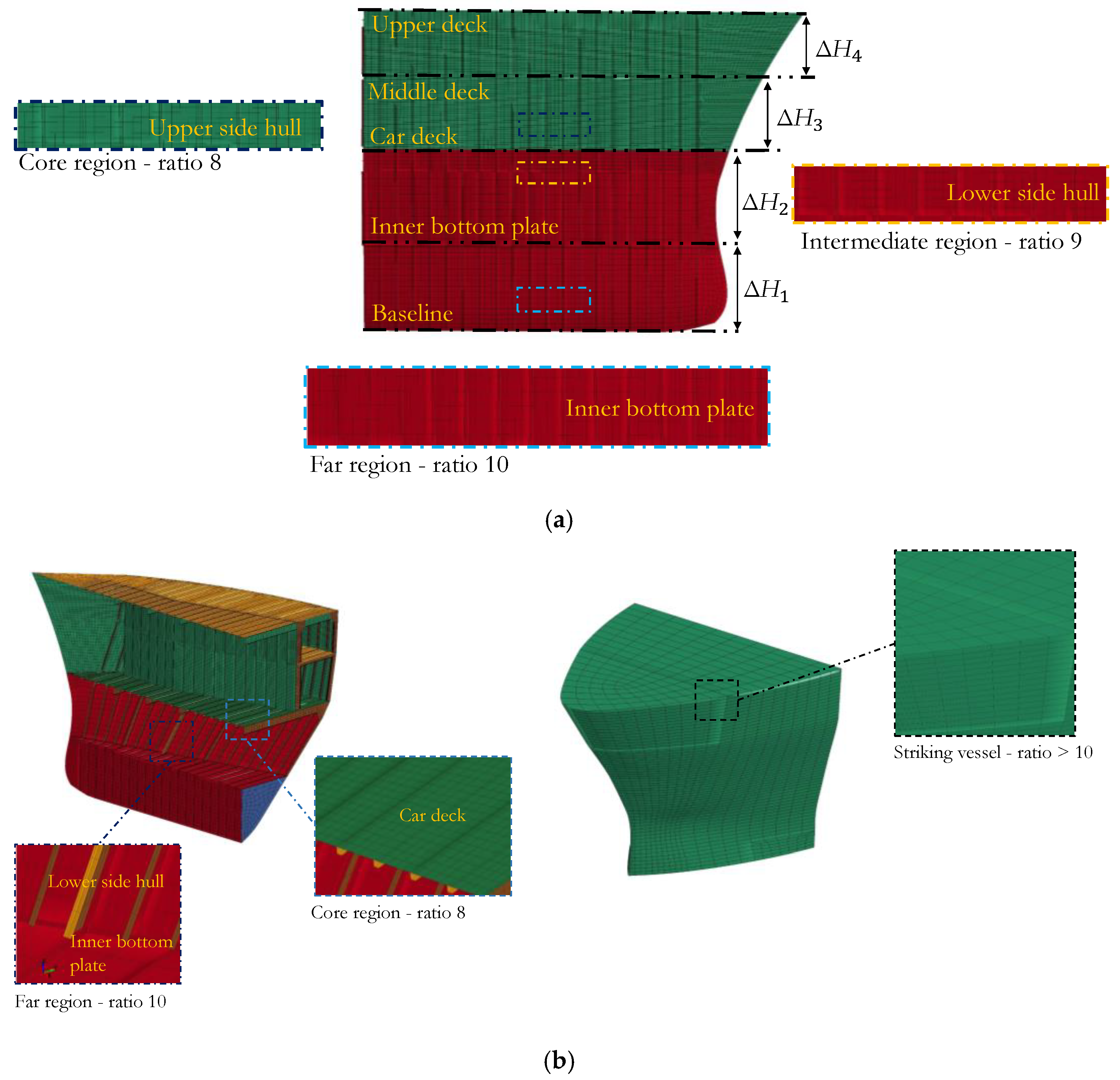
Based on these configurations, other settings were demanded on the deformable structures to ensure the rupture are well captured. In this case, the discretion of large model was an important task to be conducted, and after several works in the fields of impact engineering and crashworthiness, such as [
20,
28], the implementation of meshing size based on the ratio of element length and member thickness is proven capable of producing good results. The same strategy was applied in this work with the finest-smallest mesh of ratio 8 at the core, largest ratio 10 at the far, and ratio 9 at the intermediate region of contact. Moreover, since the striking vessel was modelled as a rigid object, the larger mesh was used to increase the efficiency of the calculation process conducted through nonlinear finite element (NLFE) ANSYS LS-DYNA. Furthermore, the large structures underwent discretization into more than 70,000 element number, and explicit methodology was chosen to calculate configuration due to its effectiveness in estimating the characteristics of impact engineering [
29].
4.2. Material Settings
The two vessels were embedded with a material model, and the strain-dependent plastic-kinematic material formulation presented in Equation (1) [
29] was applied to idealize the steel properties on the numerical model. The strain-dependent characteristic was considered because of its relation to the rupture criterion. Furthermore, as described in the previous discussion, immense structural damage is one of the casualty forms mostly observed during and after the occurrence of an accidental load. Therefore, it was necessary to define a condition when the material could be considered to have fail or ruptured and for the purpose of this study, a rupture value of 0.2 was selected. Besides failure, the Cowper–Symonds values were also defined on the material as its nonlinearity was expected since the analysis has the ability to make the material surpass yield point, therefore, value
C = 3200/s and
P = 0 were applied on the mathematical expression. However, when compared with mild steel, the value in this work is higher considering the material type selected, high-strength low-alloy (HSLA) steel (yield stress
σY = 440 MPa, density
ρ = 7850 kg/mm, Poisson ratio
ν = 0.3, hardening parameter
n = 0 and elastic modulus
E = 210,000 MPa), and effect of the impact to material behaviour.
where
σY is the yield stress,
is the strain rate,
C and
P are the Cowper–Symonds strain rate parameters,
σ0 is the initial yield stress,
β is the hardening parameter,
Ep is the plastic-hardening modulus,
E is the elastic modulus, and
is the effective plastic strain.
4.3. Boundary Conditions
The accidental load was defined as the collision between two vessels with the striking vessel hitting the designated target on the struck vessel’s side shell. Specifically, the target was placed on the car deck of the Ro-Ro below the upper and middle decks. However, in order to investigate several structural performances of the card deck, different collision angles, 60°, 90°, and 120°, were applied on the scenario configuration according to the Cartesian coordinate system. Even though the 60° and 120° are actually the same degrees in different quadrants, different results were expected due to the curve geometry of the struck vessel. The collision geometry of the NLFE analysis is presented in
Figure 3.
During vessel collision, the striking speed applied was 12 knots or approximately 6 m/s with restrained rotational displacements. The struck vessel was made constant (not moving) with the fixation attached on the edge of decks, inner bottom plate, and side transverse frame. Moreover, since collision is the main subject of this study, contact, involving frictions, is an inevitable phenomenon. Therefore, automatic contact surface-to-surface model was used to idealize the interaction of surface geometry between the struck and striking vessel, and the values of friction coefficient were set at μk = 0.57 and μs = 0.74 for kinematic and static values respectively.
5. Structural Assessments
5.1. Internal Energy
The structural assessment of the struck vessel was first conducted by observing behaviours of the internal energy, which was included in the crashworthiness criteria. The graph below illustrates the numbers of structural members destroyed on impact as well as the level of the expected damage.
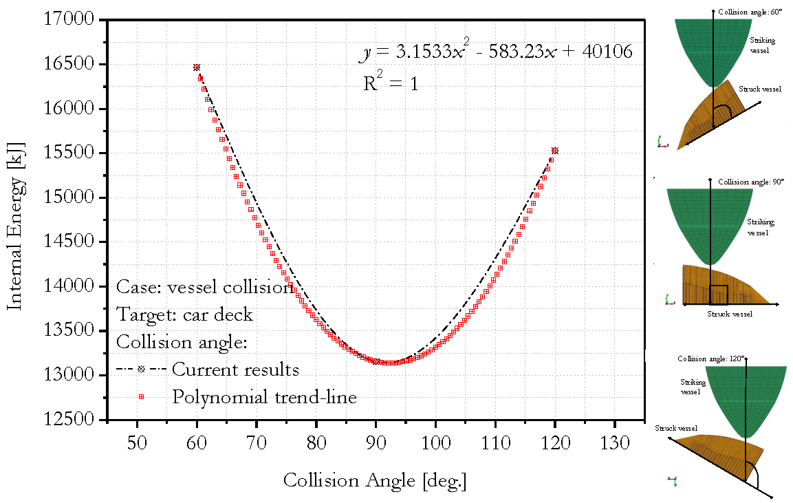
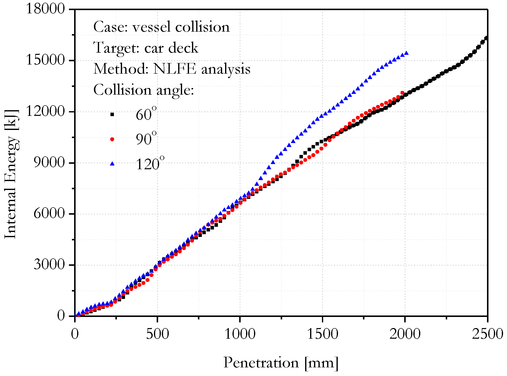
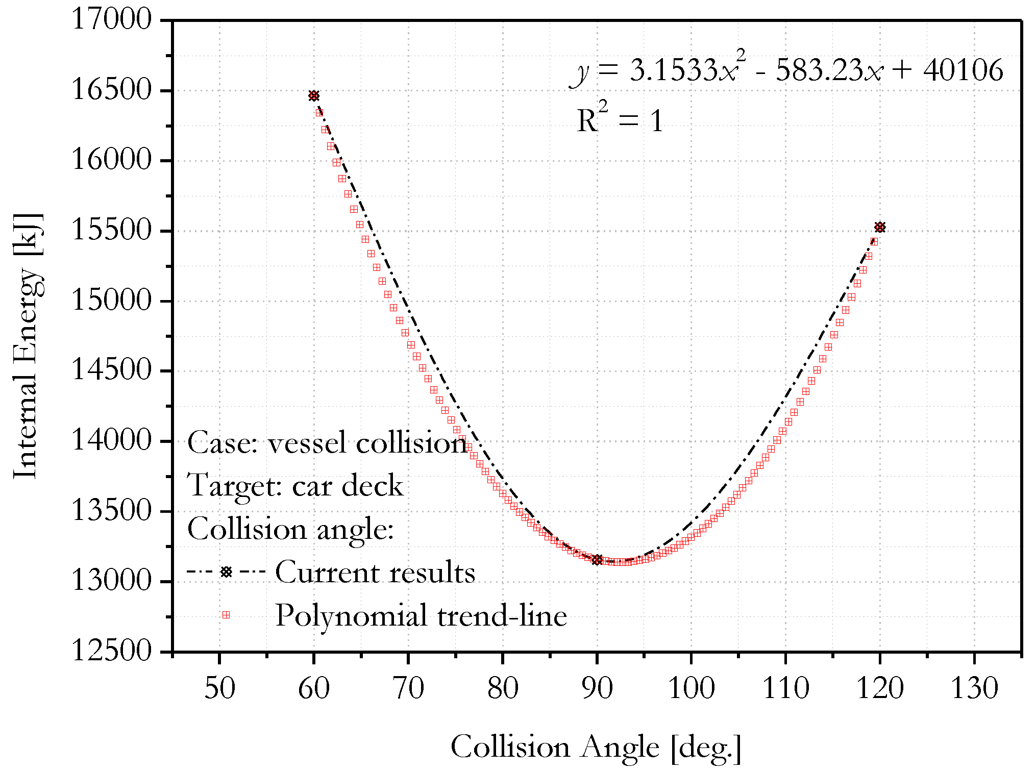
Figure 4 shows the collision angle 60° to have produced the highest energy level, followed by 120° and 90°, consecutively. The results also indicated that the destruction of the struck vessel in oblique collision 60° lasts longer, which may be important background regarding high energy pattern. Through the representation of the internal energy at the end of the collision a shown in
Figure 5, a parabolic shape was produced when the collision angle was in its vertex or lowest point.
This phenomenon suggested that during side collision, the side hull is more prone to oblique collision than a perpendicular one or perfect T-collision. This statement is founded on the less energy observed in the angle 90°, which shows that less damaged structure occurred after the collision process.
5.2. Energy Ratio
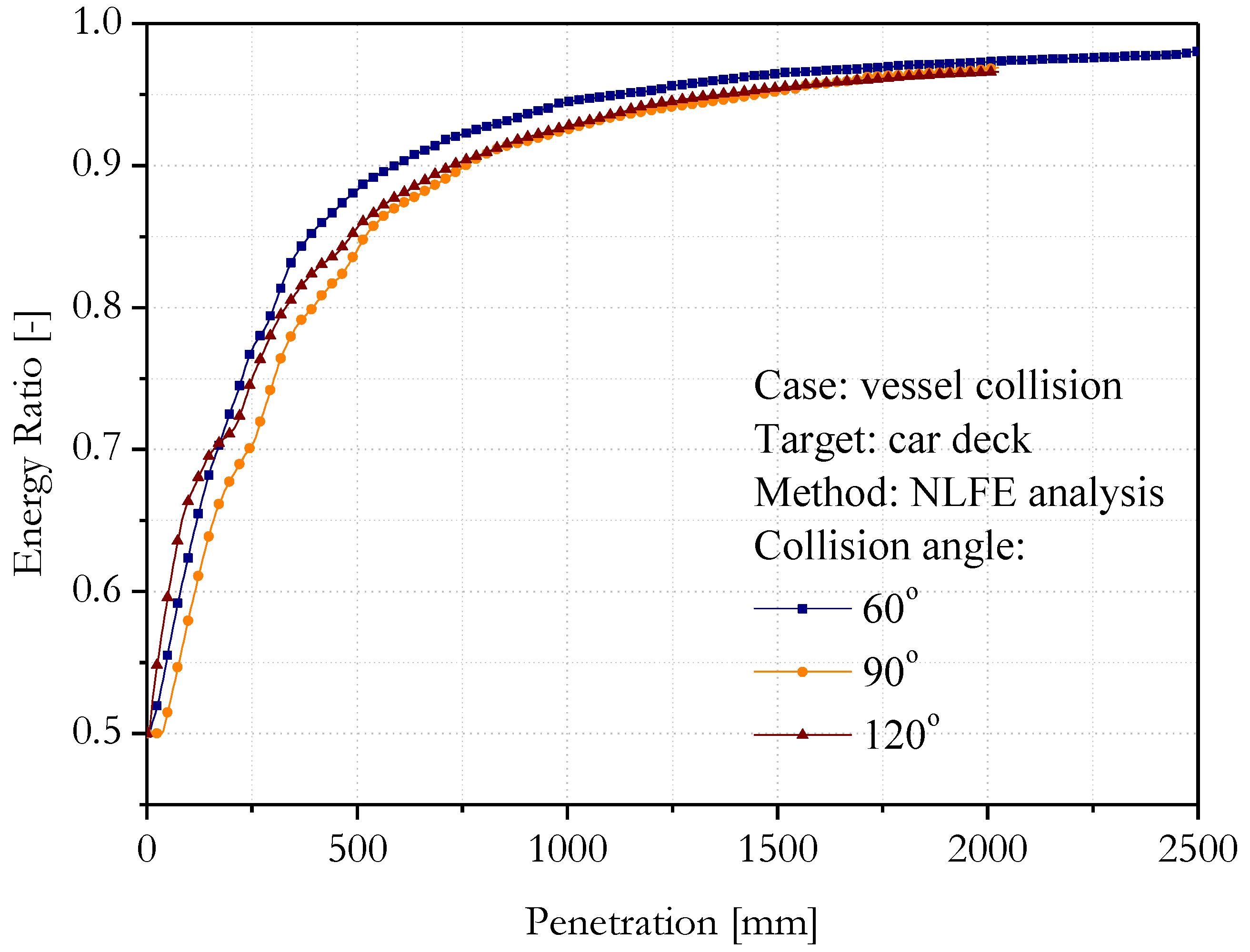
This is the proportion of the total energy in a system to the initial energy, as shown in the mathematical expressions in Equations 2 and 3. However, if the left-hand side falls below the right hand, it is possible to conclude that energy is being absorbed artificially, perhaps by an hour-glassing phenomenon, which may occur due to major damage of the idealized structures. This fundamental calculation was matched with the results in
Figure 6 where the ratio was found not to be perfectly one since some energy was affected by an hourglass. However, a very satisfying condition was indicated as the final results for all cases exceed 95%, and the hourglass proportion less than 5%. A more specific discussion on hourglass is presented in the next sub-section.
where
Ekin is the current kinetic energy,
Eint is the current internal energy,
Esi is the current sliding interference energy (including friction),
Erw is the current rigid wall energy,
Edamp is the current damping energy,
Ehg is the current hourglass energy,
is the initial kinetic energy,
is the initial internal energy,
Wext is the external work,
Eratio is the energy ratio, and
is the initial total energy.
5.3. Hourglass Phenomenon
Hourglass is a behaviour of a numerical model to be deformed in non-physical ways or geometrically due to the excessive artificially applied load. As initially predicted in the discussion of the energy ratio, a very small part of the energy was artificially absorbed by hourglass and the results presented in
Figure 7,
Figure 8 and
Figure 9 show compatibility with the prediction, even though it is minor.
The summary of the designed collision cases indicated the T-collision shown in
Figure 8 to have produced the lowest hourglass energy compared to the oblique cases in
Figure 7 and
Figure 9. However, a detail observation has the ability to identify the most contributing member in the hourglass phenomenon. Furthermore, the tendency of the car deck was observed to have produced the highest level, followed by the lower side hull, deck girder, upper side, and middle decks, respectively. It was especially found that the upper side and middle decks have extremely low hourglass with approximation in the range of 0–50 kJ. Moreover, associating the result of this subsection with the expected damage pattern after vessel collision showed a higher level of damage is experienced by a member during impact and the possibility of hourglass occurrence increase for this member. However, this leads to a very low energy value with no effect on the reliability of the present calculation. Therefore, there is need to consider an alternative to fully neutralize the hourglass in very high dynamic and nonlinear simulation and this can be achieved through the development of a fully integrated element formulation in the deformable body as conducted in [
30,
31,
32].
5.4. Rupture Strain
As defined in the numerical configuration, rupture is experienced by a material when the ultimate strain is exceeded due to accidental load. In case of the vessel collisions, the strain distribution on the struck vessel reached a quite long extent in oblique collisions of 60° and 120° as shown in
Figure 10 and
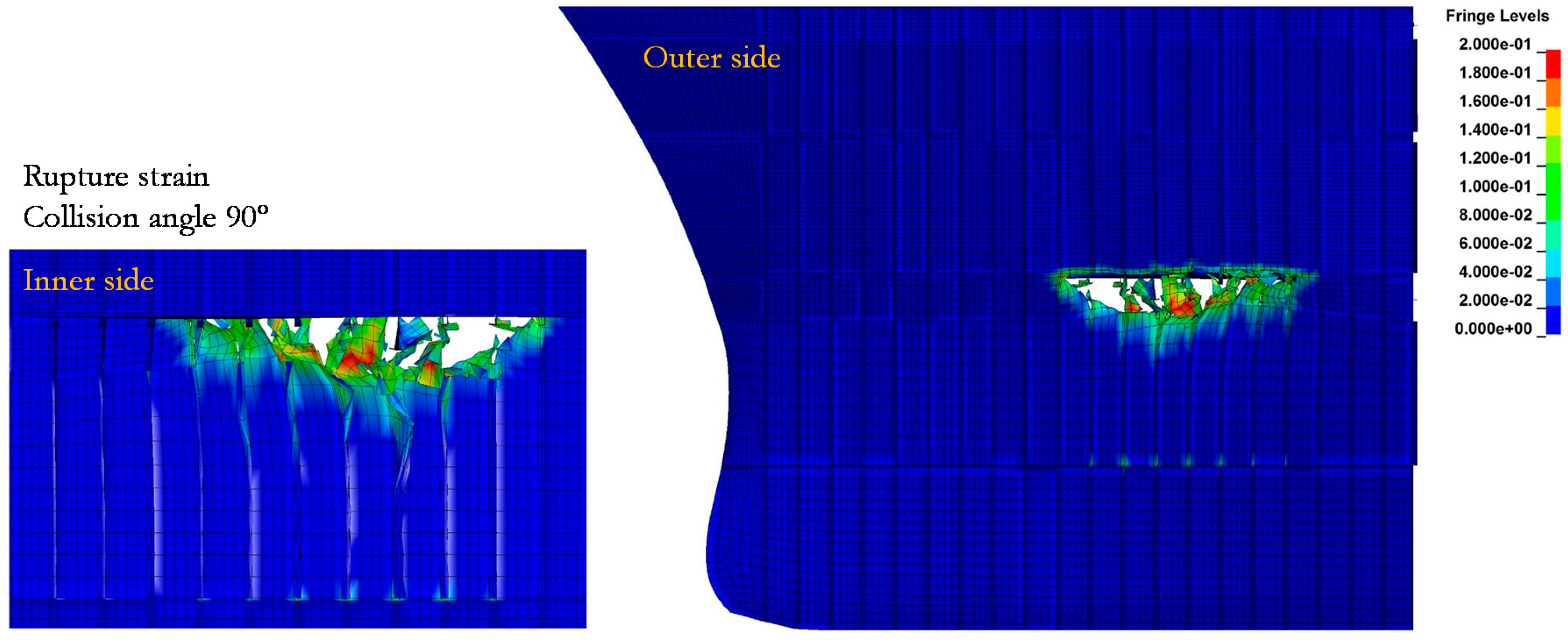
Figure 11. The strain observed indicated that the earlier contact of the side part of the striking vessel and struck vessel occurred before the tip of the striking vessel hit the target. This pattern is very different compared to the T-collision, as shown in
Figure 12. This illustration showed the opening on the struck vessel was perfect with the tip of the striking vessel which penetrated the target straight to the transverse direction. Therefore, due to more local damage on the struck vessel, the internal energy and hourglass for angle 90° were lower than the oblique cases.
The observation of the damage pattern showed the most side frame on the oblique collision 120° was folded on the lower part while the upper part was crushed and pushed on the direction of the striking angle. Furthermore, the curved geometry on the fore-peak section made the crushing pattern of two oblique collisions different even though the angle size is the same according to the Cartesian diagram. In terms of the damage extent, the collision in 60° caused longer tear on the connection of the car deck and lower side shell influenced by deeper penetration. Moreover, the calculation of the penetration in the same depth predicted the damage length to be similar in terms of size.
5.5. Critical Stress
The stress in the current structural assessment was conducted to investigate the total number of members affected due to the car deck. According to the critical stress presented by von-Mises formulation in
Figure 13,
Figure 14 and
Figure 15, the affected members for the three cases were similar, and they include car deck (main target), girder, lower hull, upper hull, and middle deck. However, despite these similarities, high-stress intensity occurred quite extensive on the lower hull of the collision case 90°. It is, therefore, possible to come up with the estimation that the collision would continue, and the part covered by high stress would experience the earliest rupture, and the element removed in the calculation. It was also noted that the oblique collisions and T-collision have a quite distinct extent in terms of damage and stress with the former having the tendency to form an incision rather than deep-focus penetration produced by the latter on the struck vessel.
The inflicted damage due to a variety of penetration styles influenced the stress contour on the side hull. Moreover, the oblique collisions in
Figure 13 and
Figure 15 caused stress distribution to the longitudinal direction of the struck vessel, while the T-collision in
Figure 14 caused high-stress intensity on the lower part of the hull opening which was explicitly distributed on the lower side hull, including its local components, such as shell and frame. This condition indicated the hull part was in a critical state before the larger tearing occurred and a deeper penetration was expected to lead to the same pattern on the side hull. A similar case is found on the 120° collision angle with the red contours spotted on the connection between the car deck and side hull. However, this spot was not a complete failure during an interaction between two ships, and the stress was intact at the end of the collision process. Therefore, the tearing length may reach this spot if a larger part of the striking bow penetrates the struck ship on impact.
6. Conclusions
This research was dedicated to investigating structural responses of the Ro-Ro vessel during a series of accidental load designed using a vessel-to-vessel collision with the angle varied in the calculation, and the analysis was conducted through the use of nonlinear finite element (NLFE) analysis. The results obtained indicated internal energy of the oblique collision case to be superior to the T-collision case, and this was verified by observing the damage level of the rupture strain and critical stress. Moreover, more local damage was produced in the T-collision case, which caused fewer casualties on the struck vessel. Besides physical behaviour, verification of the calculation process of the current work was also conducted by investigating energy ratio, and a very small portion of the energy was found to have been absorbed artificially.
Hourglass phenomenon was expected, and higher damaged members in the simulation were found to have the capability to produce higher hourglass possibility. Therefore, these findings showed energy ratio and hourglass energy to be important criteria, especially in the structural assessment of accidental load in the maritime environment, and they are recommended to be included as validation criteria in NLFE calculation considering that accidental load causes high nonlinearities. However, implementation of the current method and verification are also viable to be used in any assessment related to impact or accidental load on structures. Therefore, future work in this field should extend collision investigation by involving other angles and conduct a comparative study with a head-to-head collision case. It should also provide a concise and precise description of the experimental results, interpretation as well as the experimental conclusions to be drawn.


