SCR Performance Evaluations in Relation to Experimental Parameters in a Marine Generator Engine


Abstract
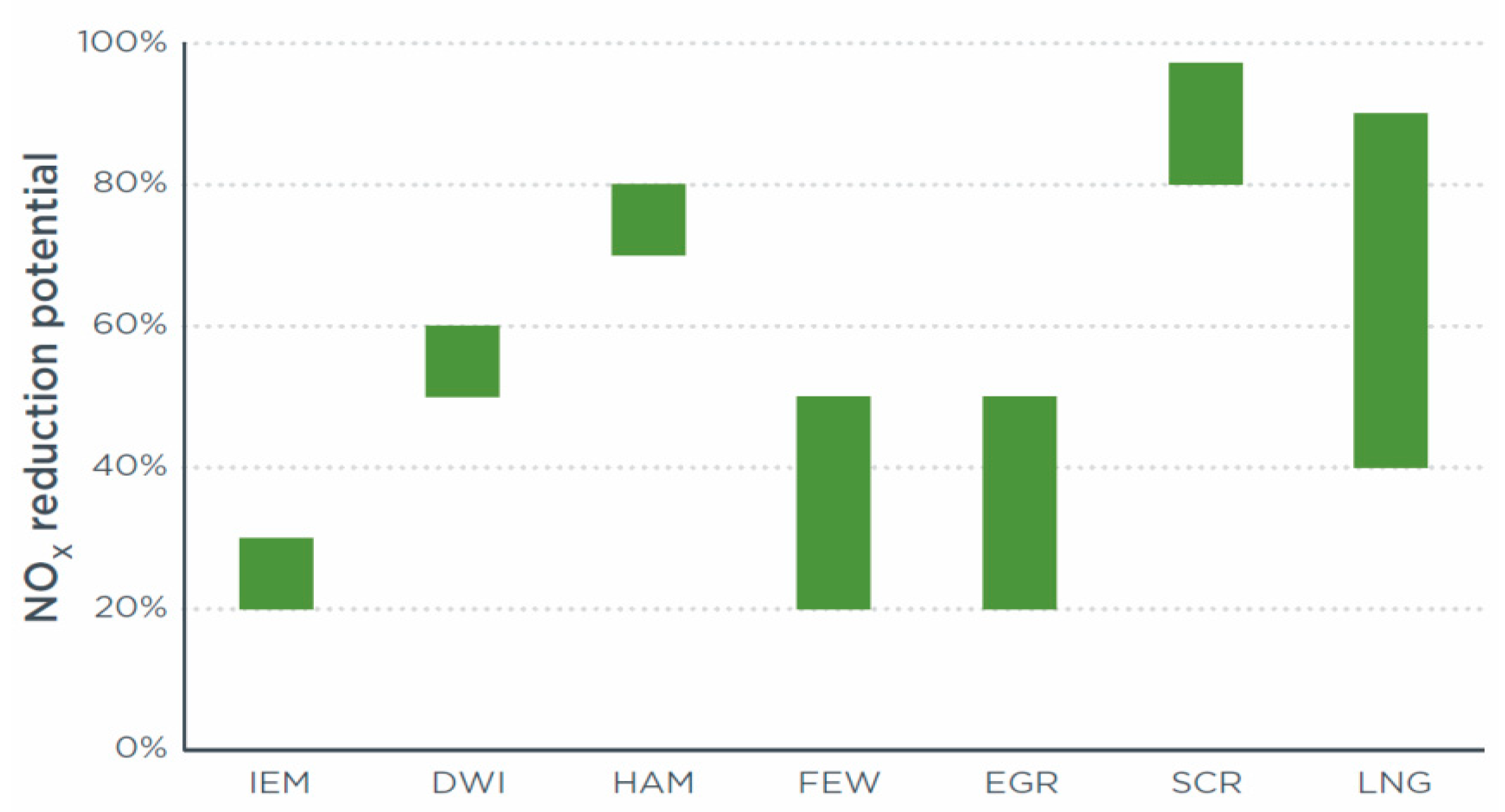
:1. Introduction
2. Apparatus and Methodology
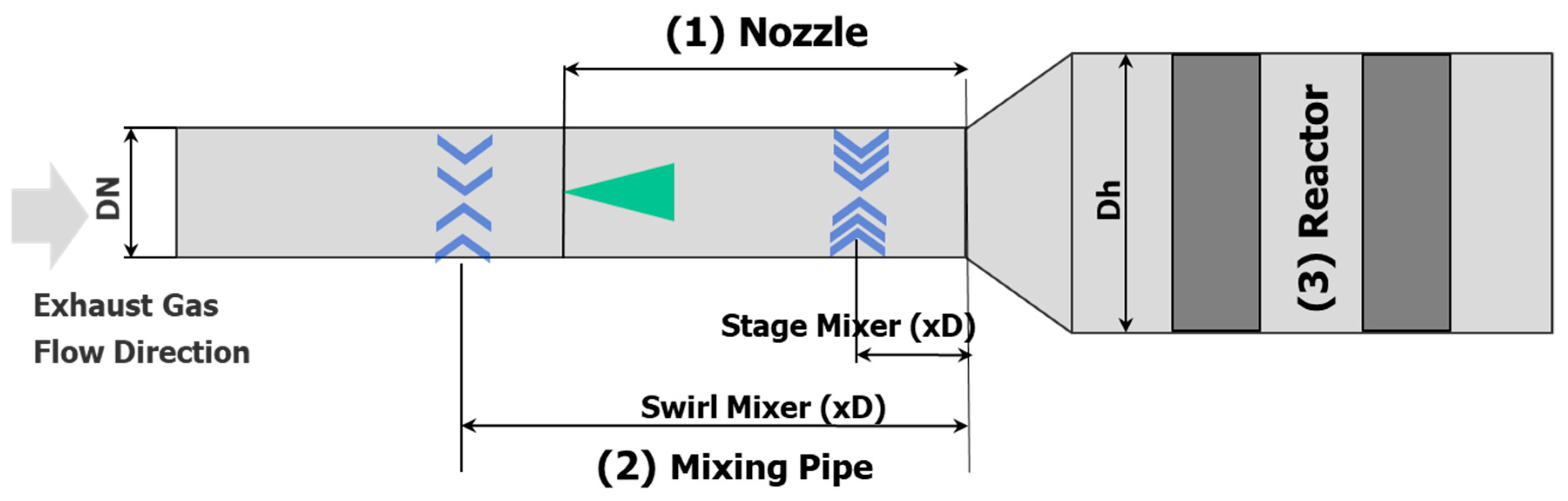
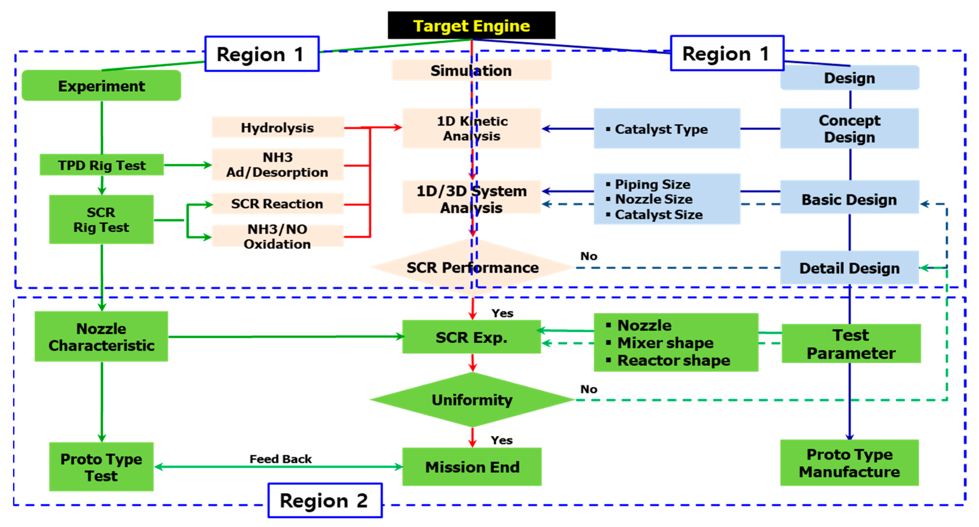
2.1. Development Process of the Selective Catalytic Reduction System
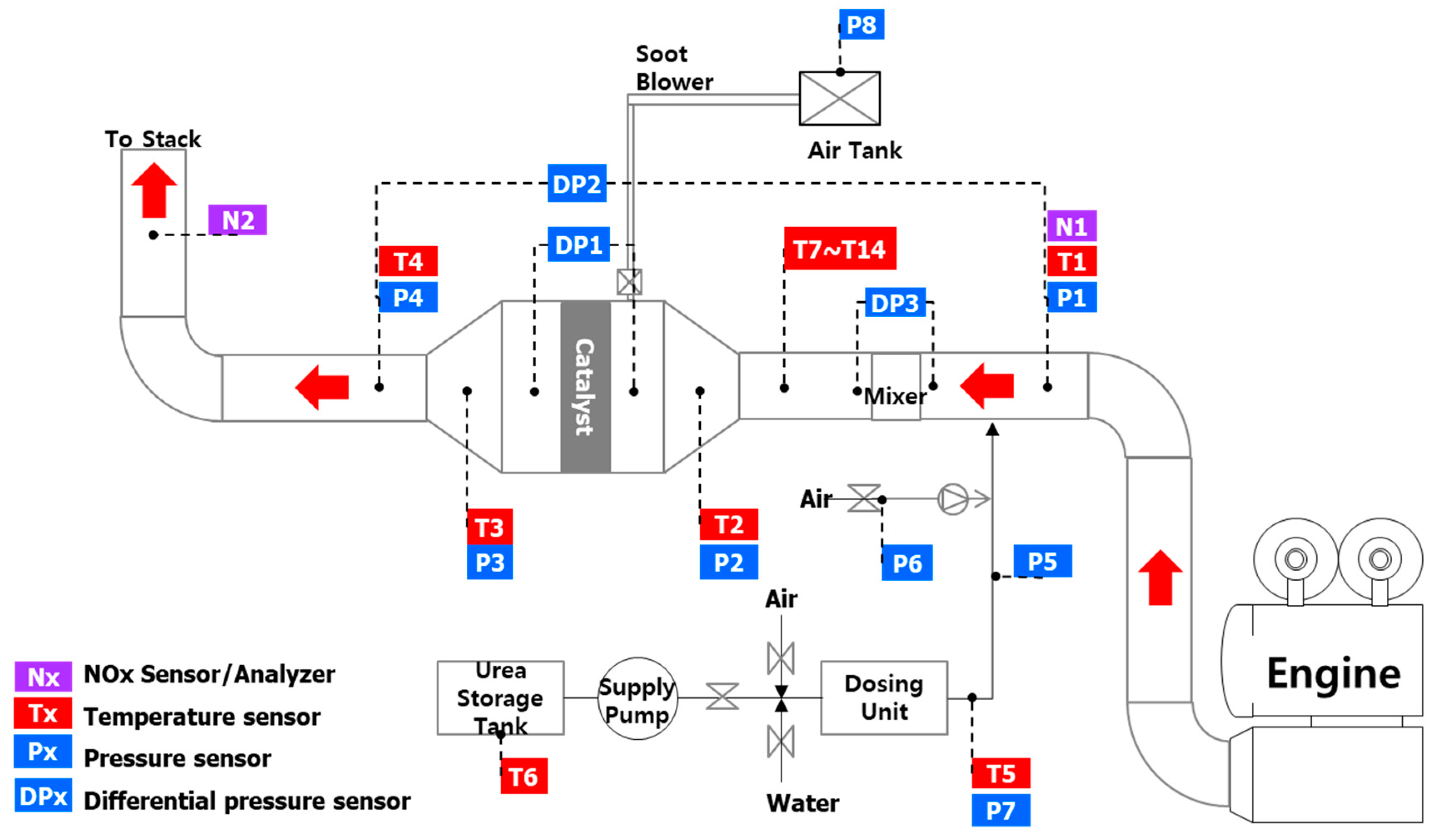
2.2. Experimental Apparatus
3. Results
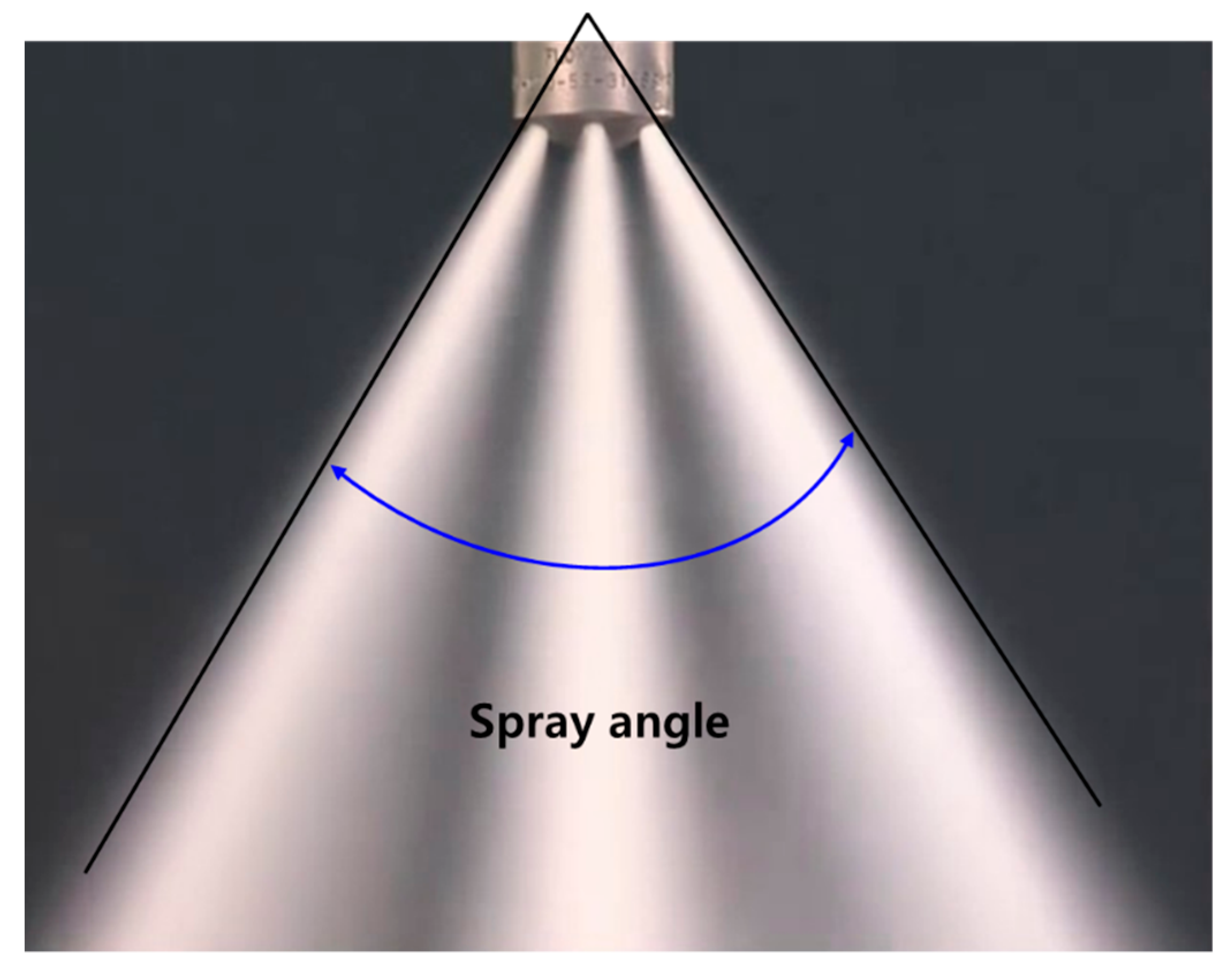
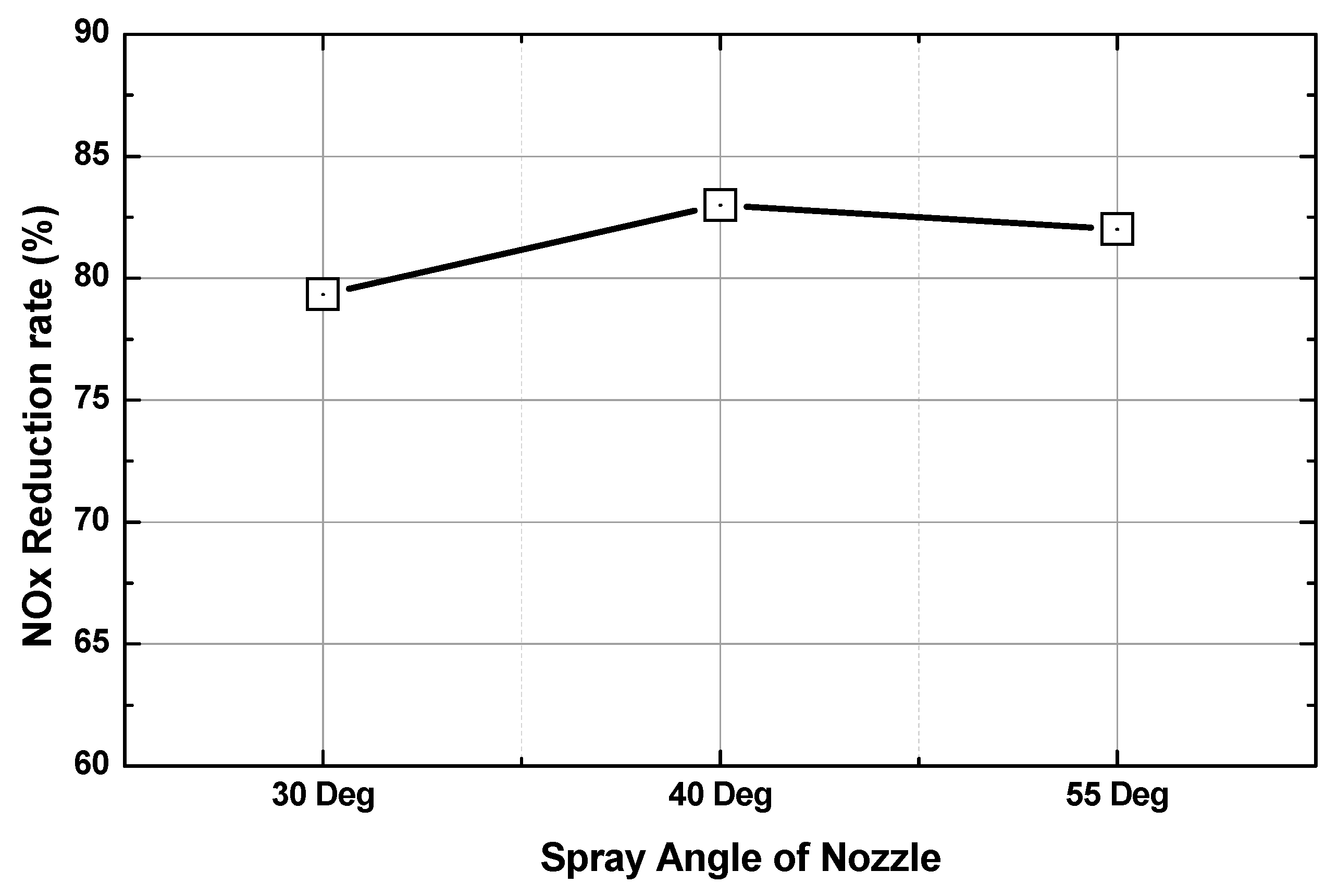
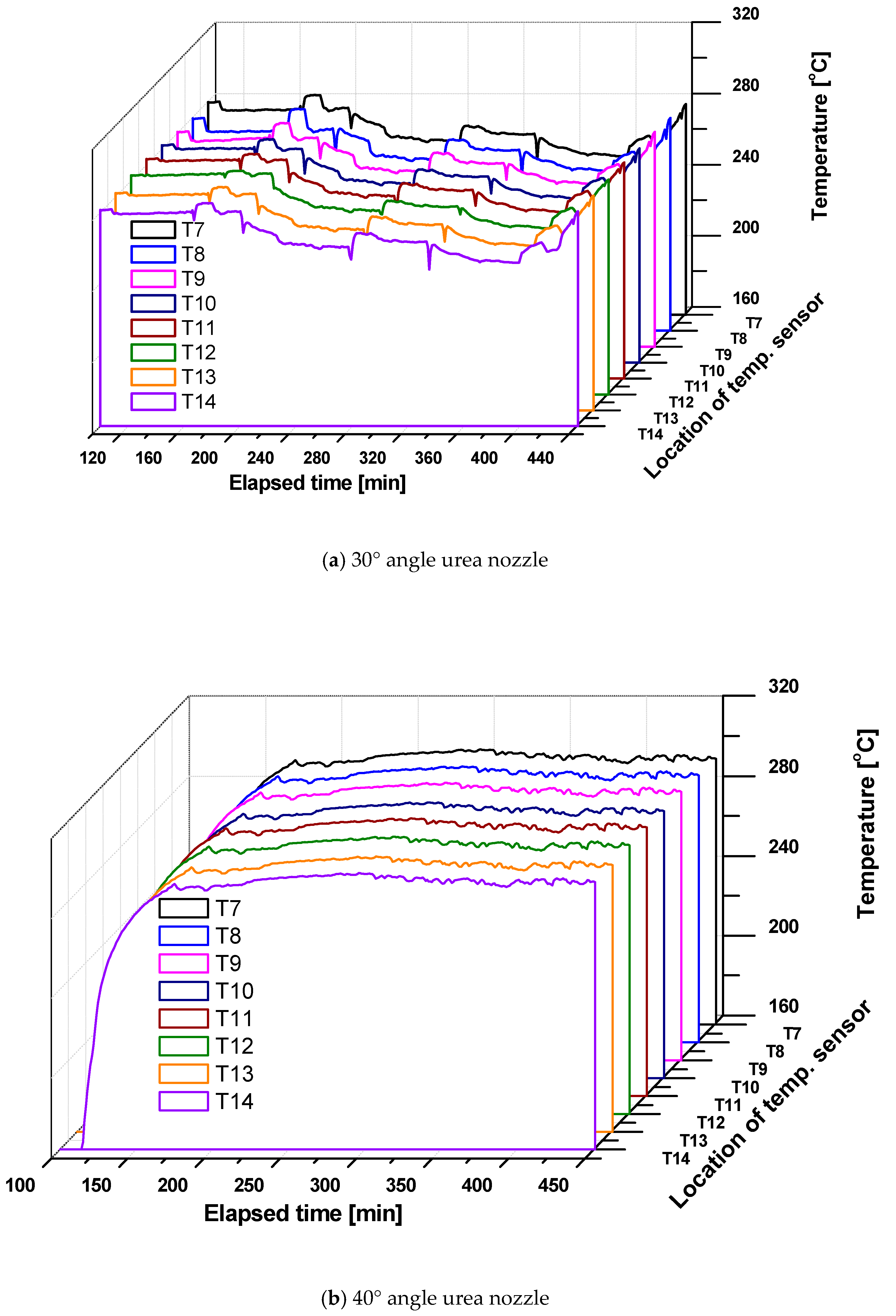
3.1. NOx Reduction Characteristics in Relation to Spray Angle and Distance of the Nozzle
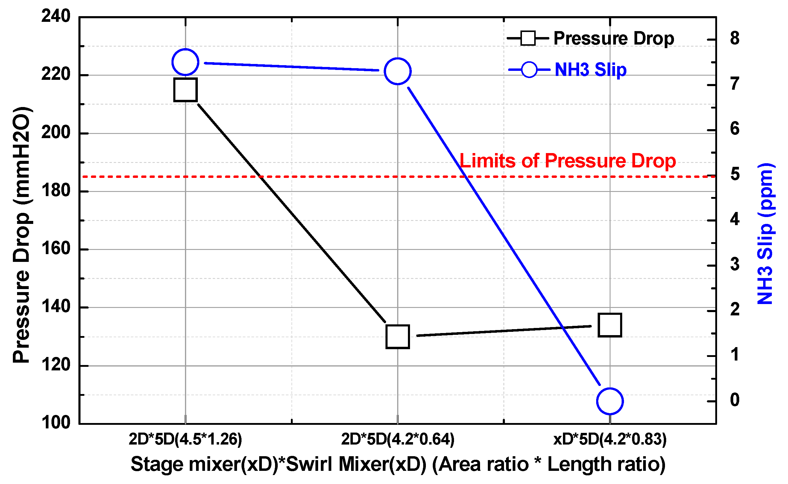
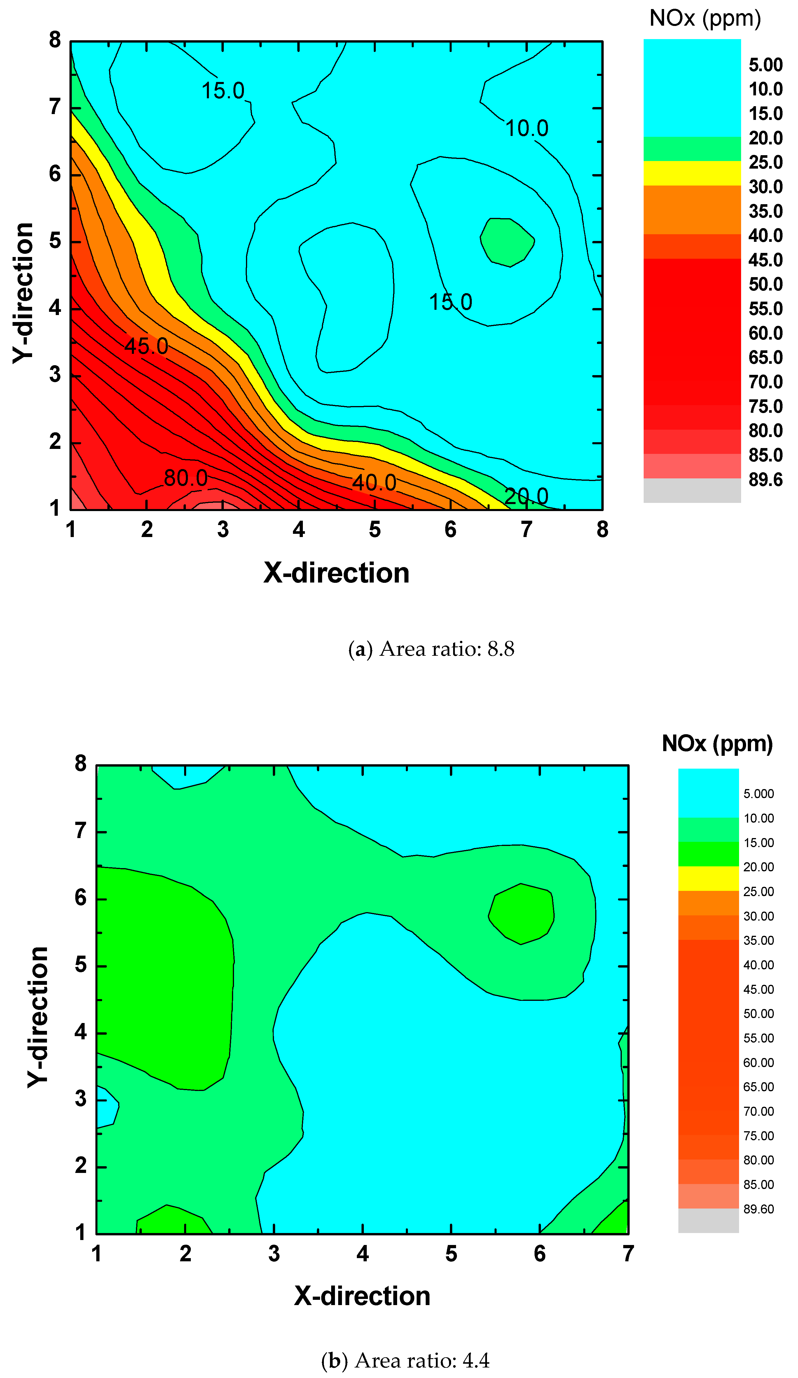
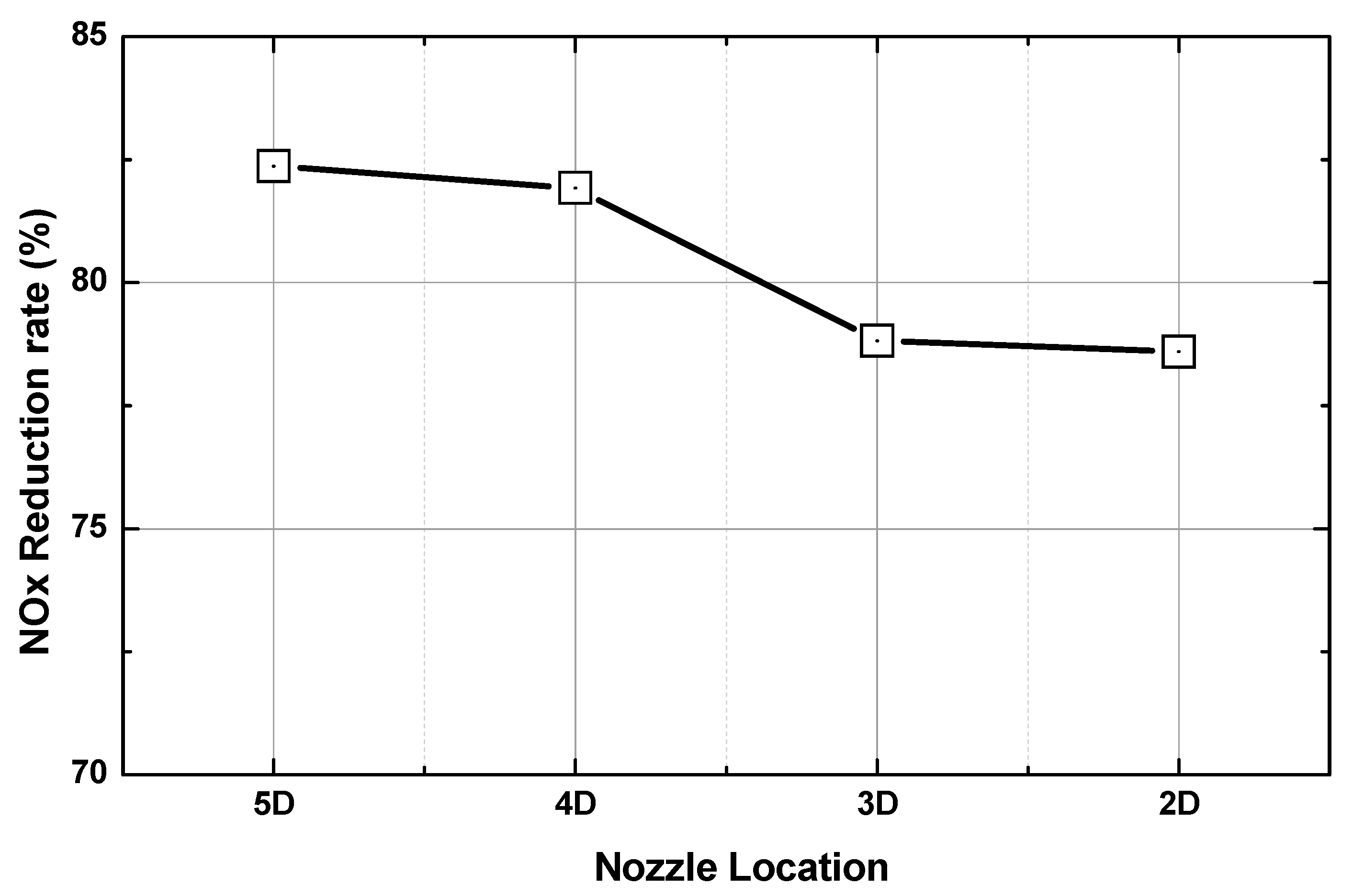
3.2. NOx Reduction Characteristics in Relation to the Location of Stage and Swirl Mixer
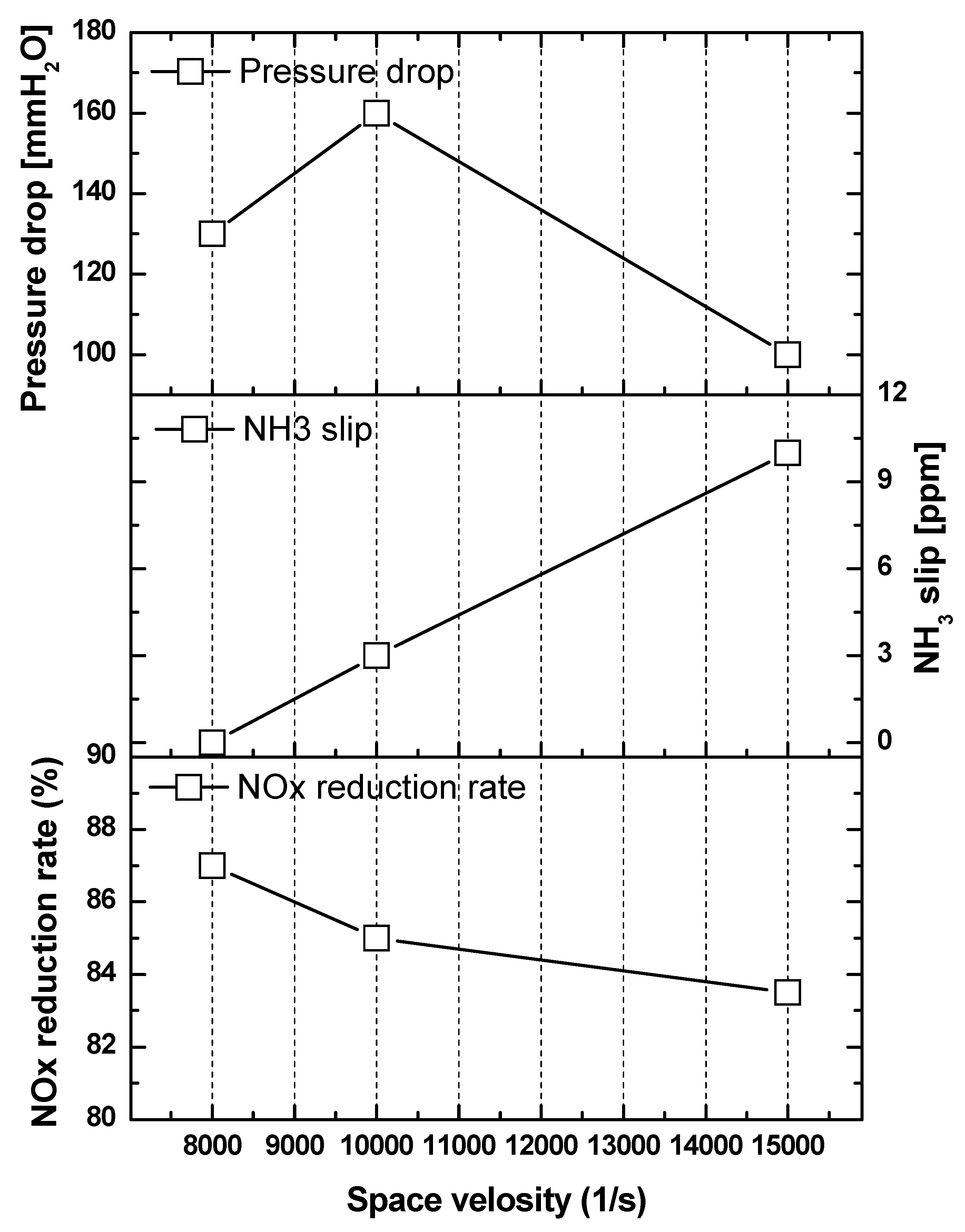
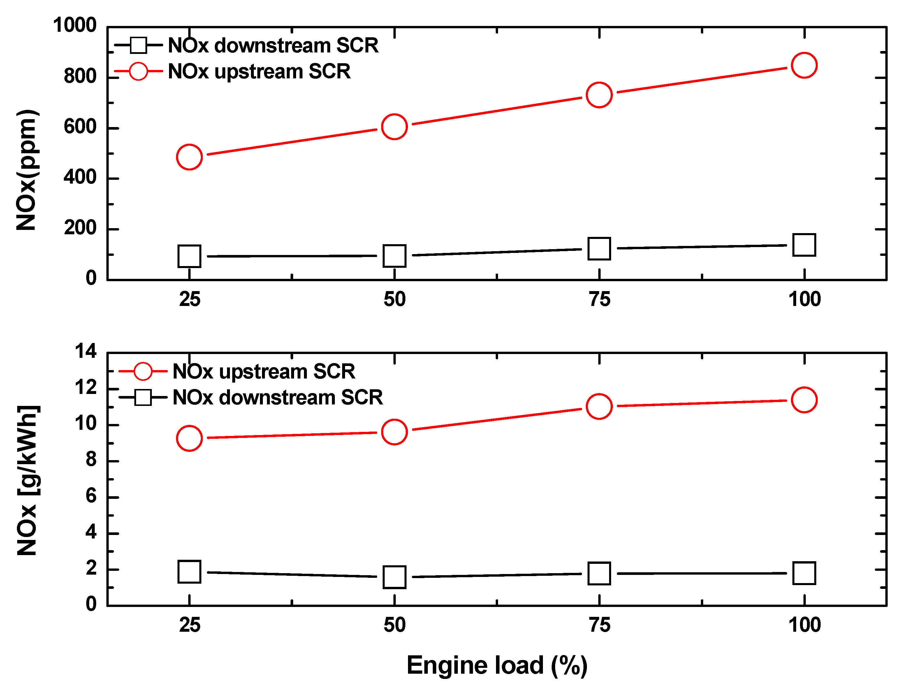
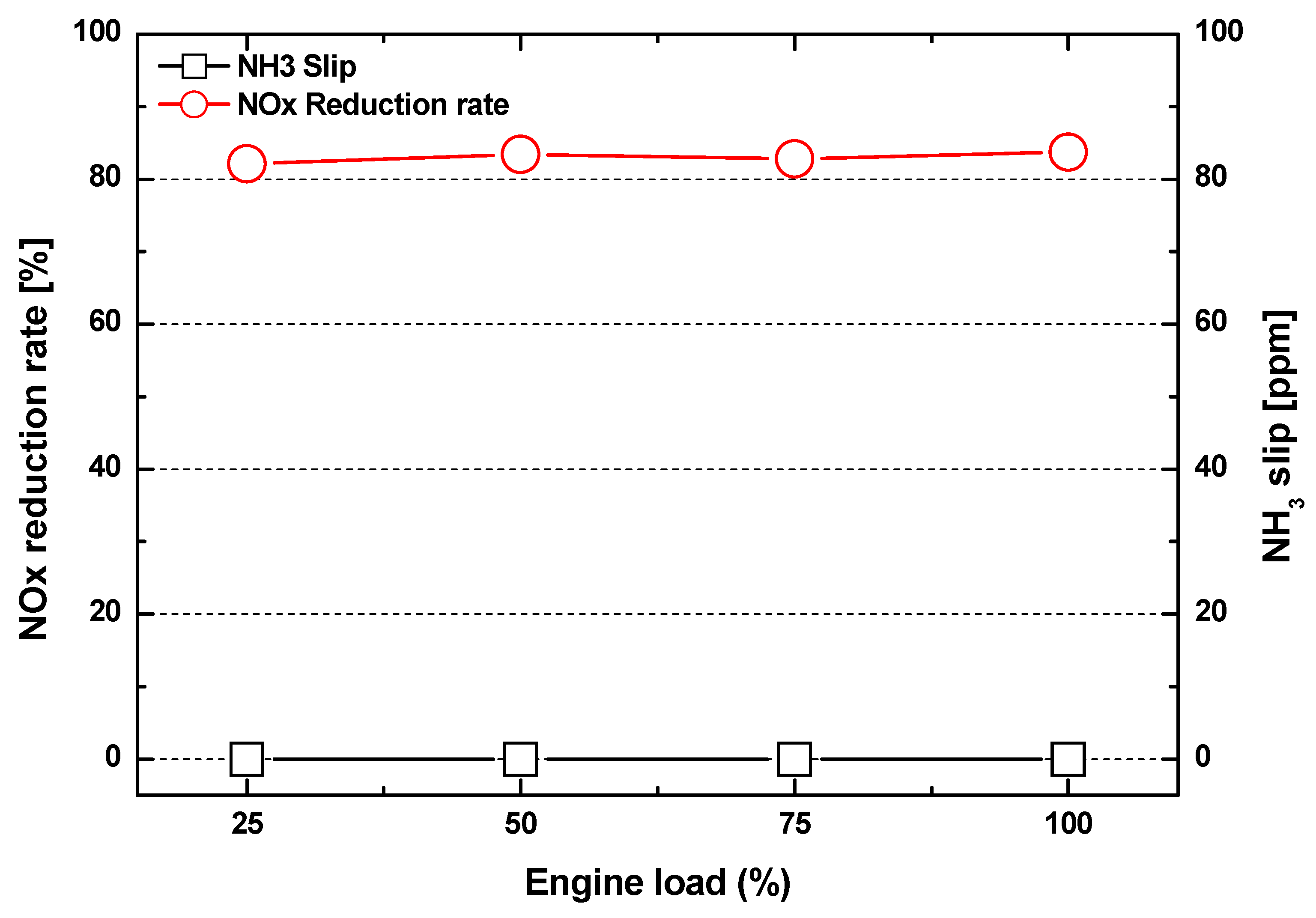
3.3. Performance of NOx Reduction Rate in Relation to Maximum Continuous Rating Conditions
4. Conclusions
- (1)
- Nozzles were selected considering the NOx conversion and NH3 uniformity characteristics according to the spray angles of the urea nozzles. Through the temperature distribution characteristics considering the spray characteristics of the sprayed urea, a uniform distribution of temperature, and reduced NOx were obtained when the spray angle was 40°.
- (2)
- To optimize the urea nozzle position, mixer position, and reactor aspect ratio, the NH3 slip was optimized for the total differential pressure of the system. The results of this study reveal that the swirl mixer was located 5D away from the reactor and the area ratio of the reactor was 4.2.
- (3)
- The NOx reduction rate and NH3 slip characteristics in relation to MCR conditions using the optimized SCR system indicated that the NOx reduction rate exceeded 80% in all MCR conditions. Finally, the SCR system developed in this study proved that the performance of the SCR system satisfied the IMO regulatory requirements.
Author Contributions
Funding
Conflicts of Interest
Acronyms
| EGR | Exhaust gas recirculation |
| SCR | Selective catalytic reduction |
| IEM | Internal engine modification |
| DWI | Direct water injection |
| HAM | Humid air motors |
| FEW | Fuel–water emulsion |
| LNG | Liquefied natural gas |
| DN | Pipe diameter |
| xD | Position of mixer located xD away from reactor inlet |
| Dh | Hydraulic diameter |
| TPD | Temperature programming desorption |
| DCU | Dosing control unit |
| FTIR | Fourier transform infrared spectrometer |
| MCR | Maximum continuous rating |
| MDO | Marine diesel oil |
| SV | Space velocity (1/h) |
| IMO | International Maritime Organisation |
References
- Heywood, J.B. Internal Combustion Engine Fundamentals, 1st ed.; McGraw-Hill: New York, NY, USA, 1988. [Google Scholar]
- Lee, C. Performance evaluation of a urea-selective catalytic reduction system in a marine diesel engine. Proc. Inst. Mech. Eng. Part M J. Eng. Marit. Environ. 2017, 231, 801–808. [Google Scholar] [CrossRef]
- Magnusson, M.; Fridell, E.; Ingelsten, H.H. The influence of sulfur dioxide and water on the performance of a marine SCR catalyst. Appl. Catal. B Environ. 2012, 111–112, 20–26. [Google Scholar] [CrossRef]
- Zheng, Y.G. The Study on a New Method for Flue Gas Denitration of Marine Diesel Engine; Dalian Maritime University: Dalian, China, 2012. [Google Scholar]
- Yu, W.X. Plasma Desulfurization and Denitrification and Its Application in the Study of Marine Diesel Engine Exhaust Treatment; Wuhan Textile University: Wuhan, China, 2013. [Google Scholar]
- Bunger, J.; Krahl, J.; Munack, A.; Ruschel, Y.; Schröder, O.; Emmert, B.; Westphal, G.; Müller, M.; Hallier, E.; Brüning, T. Strong mutagenic effects of diesel engine emissions using vegetable oil as fuel, Arch. Toxicol. 2007, 81, 599–603. [Google Scholar] [CrossRef] [PubMed]
- Busca, G.; Larrubia, M.A.; Arrighi, L.; Ramis, G. Catalytic abatement of NOx: Chemical and mechanistic aspects. Catal. Today 2005, 107–108, 139–148. [Google Scholar] [CrossRef]
- Forzatti, P. Present status and perspectives in de-NOx SCR catalysis. Appl. Catal. A Gen. 2001, 222, 221–236. [Google Scholar] [CrossRef]
- Forzatti, P.; Nova, I.; Tronconi, E.; Kuatov, A.; Thøgersen, J.R. Effect of operating variables on the enhanced SCR reaction over a commercial V2O5-WO3/TiO2 catalyst for stationary applications. Catal. Today 2012, 184, 153–159. [Google Scholar] [CrossRef]
- Chiker, F.; Nogier, J.P.; Bonardet, J.L. Sub-monolayer V2O5-anatase TiO2 and Eurocat catalysts: IR, Raman and XPS characterisation of VOx dispersion. Catal. Today 2003, 78, 139–147. [Google Scholar] [CrossRef]
- Emission Technology–MarQuip B.V. Exclusive Yacht Exhausts. Available online: https://www.marquip.nl/yacht-exhaust-systems/emission-technology/ (accessed on 6 March 2017).
- Vejlgaard-laursen, M. MAN Diesel & Turbo, Denmark. ‘Controlling Tier III Technologies. In Proceedings of the 28th CIMAC World Congress, Meeting the Future of Combustion Engines, Helsinki, Finland, 6–10 June 2016; p. 15. [Google Scholar]
- Wärtsilä Finland Oy. Wärtsilä Environmental Product Guide, 4th ed.; Wärtsilä, Marine Solutions: Vaasa, Finland, 2015. [Google Scholar]
- Assessments and Standard Division, Office of Transportation and Air Quality, U.S. Environmental Protection Agency. Use Testing Program for Heavy-Duty Diesel Engine and Vehicles: Technical Support Document; EPA420-R-05-006; United States Environmental Protection Agency: Washington, DC, USA, 2005.
- MARPOL Convention 73/78; Annex VI; IMO: London, UK, 2008.
- Park, J.K.; Oh, J.M.; Kim, H.I.; Lee, C. Combustion characteristics of MDO and MDO emulsion in automotive diesel engine. Trans. Korean Soc. Mech. Eng. B 2012, 36, 945–951. [Google Scholar] [CrossRef]
- Kim, M.; Oh, J.; Lee, C. Study on Combustion and Emission Characteristics of Marine Diesel Oil and Water-In-Oil Emulsified Marine Diesel Oil. Energies 2018, 11, 1830. [Google Scholar] [CrossRef]
- Verschaeren, R.; Schaepdryver, W.; Serruys, T.; Bastiaen, M.; Vervaeke, L.; Verhelst, S. Experimental study of NOx reduction on a medium speed heavy duty diesel engine by the application of EGR (exhaust gas recirculation) and miller timing. Energy 2014, 76, 614–621. [Google Scholar] [CrossRef]
- Bhaskar, K.; Nagarajan, G.; Sampath, S. Optimization of FOME (fish oil methyl esters) blend and EGR (exhaust gas recirculation) for simultaneous control of NOx and particulate matter emissions in diesel engines. Energy 2013, 62, 224–234. [Google Scholar] [CrossRef]
- Jafarmadar, S. Multidimensional modeling of the effect of EGR (exhaust gas recirculation) mass fraction on energy terms in an indirect injection diesel engine. Energy 2014, 66, 305–313. [Google Scholar] [CrossRef]
- Lee, C.H.; Lee, K.H. An experimental study of the combustion characteristics in SCCI and CAI based on direct-injection gasoline engine. Exp. Therm. Fluid Sci. 2007, 31, 1121–1132. [Google Scholar] [CrossRef]
- Lee, K.; Lee, C. An experimental study of the extent of the operating region and emission characteristics of stratified combustion using the controlled autoignition method. Energy Fuels 2006, 20, 1862–1869. [Google Scholar] [CrossRef]
- Lee, C.H.; Lee, K.H. An experimental study on the combustion and emission characteristics of a stratified charge compression ignition (SCCI) engine. Energy Fuels 2007, 21, 1901–1907. [Google Scholar] [CrossRef]
- Cimino, S.; Lisi, L.; Tortorelli, M. Low temperature SCR on supported MnOx catalysts for marine exhaust gas cleaning: Effect of KCl poisoning. Chem. Eng. J. 2016, 283, 223–230. [Google Scholar] [CrossRef]
- Guo, M.; Fu, Z.; Ma, D.; Ji, N.; Song, C.; Liu, Q. A short review of treatment methods of marine diesel engine exhaust gases. Procedia Eng. 2015, 121, 938–943. [Google Scholar] [CrossRef]
- Azzara, A.; Rutherford, D.; Wang, H. Feasibility of IMO ANNEX VI Tier III Implementation Using Selective Catalytic Reduction; International Council on Clean Transportation: Washington, DC, USA, 2014. [Google Scholar]


| Tier | Effective Date | NOx Limit (g/kWh) where, n Is rpm | ||
|---|---|---|---|---|
| n < 130 | 130 ≤ n ≤ 2000 | n > 2000 | ||
| Tier 1 | 2000 | 17 | 9.8 | |
| Tier 2 | 2011 | 14.4 | 7.7 | |
| Tier 3 | 2016 | 3.4 | 1.96 | |
| (1) Nozzle | Nozzle Angle (°) | |||
| 30 | 40 | 55 | ||
| Nozzle Location | ||||
| 3D | 4D | 5D | ||
| (2) Mixer | Stage Mixer | Swirl Mixer | ||
| No | 0D | 2D | 5D | |
| (3) Reactor | Area Ratio | |||
| 8.8 | 4.2 | |||
| Item Descriptions | Specifications |
|---|---|
| Engine type | 4-stoke turbo-charged DI Marine generator engine |
| Number of cylinders | 6 |
| Bore × Stroke (mm) | 230 × 300 |
| Fuel injection system | Mechanical pumping system |
| (Max. 1400 bar) | |
| Maximum continuous rating (MCR) | 780 kW/720 rpm |
| Fuel Type | Marine Diesel Oil (MDO) |
|---|---|
| Engine speed (rpm) | 720 |
| MCR conditions | 25%, 50%, 75%, 100% |
© 2019 by the authors. Licensee MDPI, Basel, Switzerland. This article is an open access article distributed under the terms and conditions of the Creative Commons Attribution (CC BY) license (http://creativecommons.org/licenses/by/4.0/).
Share and Cite
Kim, D.; Lee, C. SCR Performance Evaluations in Relation to Experimental Parameters in a Marine Generator Engine. J. Mar. Sci. Eng. 2019, 7, 67. https://doi.org/10.3390/jmse7030067
Kim D, Lee C. SCR Performance Evaluations in Relation to Experimental Parameters in a Marine Generator Engine. Journal of Marine Science and Engineering. 2019; 7(3):67. https://doi.org/10.3390/jmse7030067
Chicago/Turabian StyleKim, Dongkyu, and Changhee Lee. 2019. "SCR Performance Evaluations in Relation to Experimental Parameters in a Marine Generator Engine" Journal of Marine Science and Engineering 7, no. 3: 67. https://doi.org/10.3390/jmse7030067
APA StyleKim, D., & Lee, C. (2019). SCR Performance Evaluations in Relation to Experimental Parameters in a Marine Generator Engine. Journal of Marine Science and Engineering, 7(3), 67. https://doi.org/10.3390/jmse7030067