Article

Identifying the Design Alternatives and Flow Interference of Tuna Purse Seine by the Numerical Modelling Approach

1
Fisheries College, Ocean University of China, Qingdao 266003, China
2
College of Marine Sciences, Shanghai Ocean University, Shanghai 201306, China
3
Faculty of Marine Science, Tokyo University of Marine Science and Technology, Minato, Tokyo 108-8477, Japan
4
School for Marine Science and Technology, University of Massachusetts Dartmouth, New Bedford, MA 02744, USA
5
Shimonoseki Research Institute, Nichimo Co., Ltd., Shimonoseki, Yamaguchi 750-1136, Japan
6
Institute of Industrial Science, The University of Tokyo, Kashiwa, Chiba 277-8574, Japan
*
Author to whom correspondence should be addressed.
J. Mar. Sci. Eng. 2019, 7(11), 405; https://doi.org/10.3390/jmse7110405
Submission received: 5 October 2019 / Revised: 31 October 2019 / Accepted: 6 November 2019 / Published: 8 November 2019
(This article belongs to the Section Ocean Engineering)

Abstract

:
Dynamic responses of tuna purse seine to currents were numerically studied with regard to the vertical subsidence and global load distribution, and determinant attributes were identified. We rebuilt the submerged geometry of a purse seine net using the lumped mass method with hydrodynamic coefficients obtained from measurements of the prototype material, as well as a mesh grouping method, which corrects the twine diameter and netting material density for the equivalent net by introducing the compensation coefficient. Uneven tension distribution showed that it was vulnerable to high loads in the bunt area at shooting and along the lead line at pursing. High loads were present at the convex sections of net circles in the direction of the current. Higher shooting speeds resulted in well-balanced sinking, while a reduced hanging ratio of netting panels was beneficial to faster sinking. While large mesh sizes reduce water resistance and increase sinking velocity, extensive use should be cautioned in terms of the sensibility to stress. Comparing two options of different proportions of large-mesh panels, mesh sizes doubled for 15 strips versus 5 strips, suggesting that the 15 strip option would pose a higher risk of strand vulnerability, while the 5 strip option may be a more balanced alternative with a lower mesh density and a lower mesh stress.

1. Introduction

Tuna purse seine is one of the largest and technologically sophisticated fishing gears, which has been the predominant contributor to the total annual landings of various tuna species [1,2,3]. The development of tuna purse seines has undergone a series of trials and errors for several decades since the first use of nylon materials in purse seines in 1956. Feedback loops of fishing performance in the sea and design alterations on the land promoted its evolution, together with matching vessels and their deck machinery and wheelhouse equipment. Net configurations, however, vary throughout the world. For example, Japanese fleets often use knotless webbing of polyamide and polyester as net material, while braided knotted webbing with heavier sinkers are popular with U.S., European Union, and Chinese vessels [4]. Typically, a seine net has a combination of tapered net panels of different mesh sizes, which constitute the different parts of the gradual transition from the bunt to the main body of the gear. The top of the net is framed by a float line with distributed buoyancy to keep the top edge of the net on the surface, while a metal chain is attached to the lower edge to facilitate sinking. A purse line runs through purse rings spaced along the lower edge so that the bottom of the purse seine can be closed. A purse seining operation starts by an encircled cast surrounding the shoal of fish near the sea surface, which thereafter impounds the fish by pursing [5,6]. It is thus essential to ensure a rapid deployment and quick descent of the net to prevent the fish from escaping before the completion of pursing. Different from other stationary or mobile fishing gears, purse seines suffer from a continuous and irregular change of tracks and shapes owing to vessel manipulation and currents on the surface and at depth. Therefore, purse seines behave with dynamic equilibrium characteristics over time and space during the entire operation.
The net shape is potentially subjected to impacts from net construction, operational skill, and procedures, as well as the presence of and changes in ocean currents. In particular, the geometrical shape could be severely deformed when exposed to rough seas with strong surface currents or unfavorable combinations of multi-layer currents. The magnitude of current velocity, for instance, as demonstrated from a mixed factorial model, has a quadratic effect in impeding vertical sinking [7]. However, alternative shooting patterns can effectively reduce such negative effects by changing the relative orientation between the net circle and the current. Different shooting patterns, such as forward-set, counter-set, or cross-set, can lead to various shape-transforming reactions [8].
Improvement in fishing performance can be achieved through alternative structures of fishing gear to increase energy efficiency or to improve handling and maneuvering. A large number of studies reported design alternatives by either setting up a small-scale model net to reconstruct the actual conditions in flume tank experiments or directed field measurements of full-scale nets regarding netting materials [9], hanging ratio [10], and net structure [11]. Although both methodologies are valid, challenges remain owing to the following reasons: (i) scale effects increase inaccuracy in results owing to the small-scale model net’s fit to the flume tank; (ii) the large dimension of prototypes in the field has a very limited field of view.
Technical disadvantages in both the model and field experiment have led to extensive application of numerical approaches to help in the understanding of the geometry of submerged nets in fishing operations. Among available numerical models, the lumped mass method with connected springs based on individual twine, and the finite element method with a trussed net element, are the most representative models. For either method, it depends on the accurate estimates of hydrodynamic coefficients, which have been substantially studied in fluid load tests [12,13,14,15,16]. There is, however, no universally accepted empirical formula because of the influence of mixed factors such as Reynold’s number, solidity ratio, and netting material. For purse seines, the earliest mature dynamics model was developed using the mass-spring method with mass concentrated to make the simulated shape visible [17]. Successive research demonstrated the validity of the model with measured data from the sea trial, which evaluated the effects of netting density and sinker weight, among other factors [18]. Owing to effective monitoring and prediction of the net shape in the numerical approach, more details and arguments were put forward, for example, the transformation of the float line and purse line as the seiner drifted toward inside the net circle [19]; the substitution of a large-mesh panel with a prototype for superior performance of sinking and mechanics [20]; and the possibility of controlling the depth of the lower edge of the net by regulating the shooting speed to avoid grounding [21].
Scientific assessment and prediction of net performance in advance contribute to the improvement of efficiency in the stage of design or modification, and to the prevention of abortive casting and net damage during the operation. Gear innovation has been experiencing a global prevalence of larger mesh sizes in purse seines. For example, tuna purse seines used by Chinese fleets often have float lines with lengths of over 1600 m, and are made up of 29 strips of netting panels with a maximum mesh size of 260 mm in the main body and 90 mm in the bunt. Japanese-style purse seines even have larger meshes in some portions of the net—more than 300 mm, and even approaching 450 mm in some cases. Enlarged meshes can not only allow faster sinking, but also possibly reduce the catch of juvenile tuna. However, whether (and where) to use large meshes should be carefully evaluated as a matter of trade-off between low water resistance (higher sink velocity) and high probability of mesh breakage. We thus applied a dynamic simulation of the lumped mass method to reproduce the underwater dynamic behavior of the net, and to provide insights into the distribution of tuna purse seine load at the termination of shooting and pursing, so as to provide optimal netting assemblage. We also refined the meshing grouping method by distinguishing the twine diameter and netting material density between prototype and equivalent net. To improve the accuracy of the results, we also conducted flume tank tests to obtain hydrodynamic characteristics of nylon netting used in the purse seine to provide the empirical formula of drag and lift force coefficients in relation to attack angle, solidity, and Reynold’s number. From the above, we identified design alternatives and how current interferences would account for the rationality of the structure and operation of the purse seine from mesh size, hanging ratio, shooting speed, and current pattern, which influence net deformation.

2. Physical Model Framework and Prototype Validation

2.1. Lumped Mass Method

Purse seine is a combination of some basic components including netting panel, sinker, float, and rope, which differ as particular geometric units in physical properties. Topologically, the sinker and float are simplified to spheres with only external forces, while the rope and mesh are considered finite elements of a cylinder elastically trussed to the nodes. In the lumped mass method, a mesh bar is considered as a cylindrical unit, but with the load and mass uniformly transferred to the knots on both ends. Between mass points is assumed to be a spring, which allows tensile forces to be exerted on it. Mass points are connected together in this way to maintain system function.

2.2. Mechanics Analysis

The motion of mass points in the fluid is dominated by the resultant apparent weight W, tensile force T, and fluid force F, where apparent weight is the result of buoyancy B and gravity G (Figure 1a). For a single mesh bar, apparent weight is expressed as follows:
W = G + B = ( ρ p ρ w ) π 4 d 2 l 0 g ,
where ρp is the density of the net material, ρw is the density of the fluid, d is the diameter of the net bar, l0 is the initial length of the bar, and g is the gravitational acceleration.
The bar elements are assumed to be elastic in traction and incompressible in compression, that is, free force when the distance between two mass points is less than the initial length of the bar. The tensile force, acting on two adjacent mass points, is a linear augment with elongation of the bar element. It is represented by the following equation with regards to the tensile force between the given mass point and one of the adjacent mass points:
T = E A ( | r | l 0 ) l 0 n ,
where E is the Young’s modulus, A is the sectional area of bar equal to πd2/4, r is the vector from mass point to its adjacent mass point, and n is the unit vector of r . The total tensile force of the given mass point is the resultant vector of tensile forces between this mass point and others connecting it.
Fluid exerts two forms of force, the inertial force and the velocity-induced hydrodynamic force, which is composed of drag force FD and lift force FL. Mass points, which situate in the unsteady flow, experience inertial force along the flowing direction from the accelerating fluid and additional mass force derived from the velocity change of the surrounding fluid under disturbance. However, in the case of a uniform current, owing to the accelerated motion of mass points, the fluid particles around the mass points are still disturbed and will exert the additional inertial force on the mass points. For each mesh bar, the drag and lift force are expressed as follows, respectively:
F D = 1 2 C D ρ w s ( | v v p | ) 2 n d ,
F L = 1 2 C L ρ w s ( | v v p | ) 2 n l ,
where CD is the drag coefficient; s is the projection area of bar equal to d·l0; v is the vector of flow; n d is the unit vector of drag; v p is the vector of the motion for mass point; CL is the lift coefficient; and n l is the unit vector of lift force, which lies in the plane formed by the vector of drag and cylinder, and perpendicular to the direction of drag force.
The direction vectors of drag and lift force are defined as follows:
n d = v v p | v v p | ,
n l = ( r × n d ) × n d | ( r × n d ) × n d | r n d | r n d | .

2.3. Mesh Grouping Method

Given diamond-mesh netting with the mesh numbers m × n, the grouping ratio r was defined, which represented an equivalent net with total number of meshes decreased by r2 times (Figure 1b). We first determined the twine diameter of equivalent net based on the criteria of constant hydrodynamic force. In most cases, the sinking process of seine net was considered to be the situation of netting parallel to flow. We fixed the relationship between drag coefficient CD0 and Reynold’s number by defining a new characteristic length as the product of twine diameter and solidity ratio. On the basis of non-linear fit, the dependence of drag coefficient CD0 was expressed as follows:
C D 0 = 0.9 Re s 0.2 ,
where Re s is new-defined Reynold’s number with the characteristic length expressed as d·S.
In order to retain the constant of hydrodynamic force, the following equation can be derived as follows:
( d 2 l ) 0.2 d l = ( d e 2 l e ) 0.2 d e l e ,
where d and l are the diameter and net bar length of the prototype, respectively; de and le are the diameter and net bar length of the equivalent net, respectively; and le/l = r.
On the basis of the above formula, we can obtain the twine diameter of the equivalent net as follows:
d e = d r 4 3 .
In order to retain the constant of gravity in water, it is necessary to compensate for the density of material, that is, the equivalent net adopts a different density of netting material from the prototype. Thus, the equation can be satisfied as follows:
( ρ ρ w ) m n l π d 2 = ( ρ e ρ w ) m e n e l e π d e 2 ,
where ρ is the density of netting material; terms with subscript e corresponds to the equivalent net.
Thus, the compensation coefficient τ of material density for the equivalent net can be obtained as follows:
τ = ρ e ρ = r 5 3 ( 1 ρ w ρ ) + ρ w ρ .

2.4. Kinematic Equation

Dynamic simulation is actually a problem by solving the motion of mass point through time. The basic kinematic formula of the mass point can be expressed as follows:
m a = F D + F L + T + W m a ,
where m is the mass of a mass point; a is the acceleration of the mass point in motion; and m′ is the inertial mass caused by the accelerated motion of the mass point, which is expressed as follows:
m = ρ w ( 1 + λ ) ,
where is the volume of the mass point, and λ is additional mass coefficient. As suggested by Hossenni et al. [20], the additional mass coefficient for a sphere is a constant of 0.5; for a cylinder, it is equivalent to the sine function of the angle of attack θ, and is computed as follows:
sin θ = 1 ( | ( v v p ) r | | ( v v p ) | | r | ) 2 .
Taking into account the lumped mass and force, the motion function of any mass point in the topology with the index (i, j) can be expressed as follows:
m ( i , j ) = 1 n k ( i , j ) [ T + 1 2 ( F D + F L + W ) ] = n k ( i , j ) m ( i , j ) = 1 [ 1 2 ( m + m ) ] a ,
where nk (i, j) is the number of adjoining mass points around the mass point with the index (i, j).

2.5. Hydrodynamic Coefficients

To estimate the empirical formulae of hydrodynamic coefficients, we performed tests on nylon netting in a circulating flume tank of Tokyo University of Marine Science and Technology (TUMST), with the working section of 9.0 m in length, 2.2 m in width, and 1.95 m in depth. The net panel was configured to a stainless-steel framework of 70 cm × 70 cm. A total of eight samples of netting with various solidities were placed in the direction of normal and parallel to the flow at current velocities ranging from 30 to 110 cm s−1 with 10 cm s−1 intervals. Netting panels inclined to the flow by attack angles at intervals of 10° from 10° to 80° were also measured, with each azimuth separately at current velocities of 40, 60, 80, and 100 cm s−1. The acting force was recorded by three-component force balance (full capacity 5 kgf and accuracy ±0.015 kgf) at a frequency of 20 Hz for a period of 20 s on average. The coefficients consolidated the Reynold’s number based on twine diameter (Re, ranged from 500 to 2200), attack angle (θ), and solidity ratio (S) using nonlinear regression, and obtained the following empirical formulae:
C D = 4.38 Re n 0.118 S 0.17 sin 2 θ + 0.4 Re n 0.06 S 0.33 cos 2 θ ,
C L = ( 0.34 S 0.042 sin θ + 1.15 S 0.34 cos θ ) sin θ cos θ ,
where the solidity ratio (S) is usually used to describe the geometric character of mesh. In our simulation, it was time-varying and defined as the proportion of the normal projected area of strands to the outline area after submersion.
In the case of a low attack angle, it is known that a “shadow effect” may occur as fluid transits from upstream strands to downstream strands, causing a reduction of velocity and corresponding fluid force. The influence of the shadow effect is considered maximal when the net panel is set parallel to the current. For the case when the attack angle is zero, the drag coefficient formula is given in the following form:
C D 0 = 0.23 Re n 0.06 S 0.33 .

2.6. Computation Condition

For the shooting process, we implemented idealized motion in a circular track and imitated realistic operation where the initial feature started from all nodes stacking centrally, and moved counterclockwise in a circle until submergence in proper sequence for free-sinking driven by gravity and hydrodynamics. The shooting speed was set to be 6 Kn, that is, the normally averaged vessel speed in actual operations. For pursing process, we assumed that the net was retrieved at a fixed pursing speed of 1 m s−1, and thus subject to varied towing force from the winch. The simulation was performed on a PC platform (Intel Core i5-5200, 2.2 Hz and 4 GB RAM). The grouping ratio r and speed ratio (prototype to equivalent net) were set to 100 and 1.54, respectively, as the rational choice depending on the memory and running time. A total of 3100 mass points were involved in the system with a step size of one millisecond. As the input arguments, Young’s modulus and density for nylon twine were set to be 200 GPa and 1140 kg m−3, respectively; the sinking chain and floats were regarded as an iron sphere with a constant drag coefficient of 0.47 and density of 7900 kg m−3.

2.7. Numerical Solution

Regarding the fact of a complicated stiff equation sensitive to the algorithm, we used an implicit predictor–corrector method based on i + 1 iterations to ensure the precision and stability of the numeric solution. We assumed that the velocity vp and acceleration a of mass points at time k = 0 are infinitely close to 0. The initial value (0-th iteration) of velocity and coordinate y at time k + 1 are acquired by the Euler method as follows:
{ v p k + 1 ( 0 ) = v p k + Δ t a k y k + 1 ( 0 ) = y k + Δ t v p k a k + 1 ( 0 ) = f ( y k + 1 ( 0 ) , v p k + 1 ( 0 ) ) .
Velocity and coordinate at (i + 1)th iterations at time k + 1 are repetitiously corrected by a trapezoid formula as follows:
{ v p k + 1 ( 1 ) = v p k + Δ t 2 [ a k + a k + 1 ( 0 ) ] v p k + 1 ( i + 1 ) = v p k + Δ t 2 [ a k + a k + 1 ( i ) ] y k + 1 ( 1 ) = y k + Δ t 2 [ v p k + v p k + 1 ( 0 ) ] y k + 1 ( i + 1 ) = y k + Δ t 2 [ v p k + v p k + 1 ( i ) ] a k + 1 ( i + 1 ) = f ( y k + 1 ( i + 1 ) , v p k + 1 ( i + 1 ) ) .

2.8. Prototype Verification

Field measurement was carried out onboard a Chinese tuna purse seiner during an actual fishing operation within the exclusive economic zone (EEZ) of Papua New Guinea. We performed a general linear fit (generalized linear model, GLM) to the dataset using an identity link function to extract the contributing factors associated with the sinking depth, and obtained the standardized regression model (see model protocol in Zhou et al. [7]). This is reliable for predicting the maximum sinking depth applicable for any cases; therefore, it can be used to compare simulation results under the same conditions. The design drawing and parameter specification of actual fishing gear is shown in Figure 2, Table 1, and Table 2.

3. Results

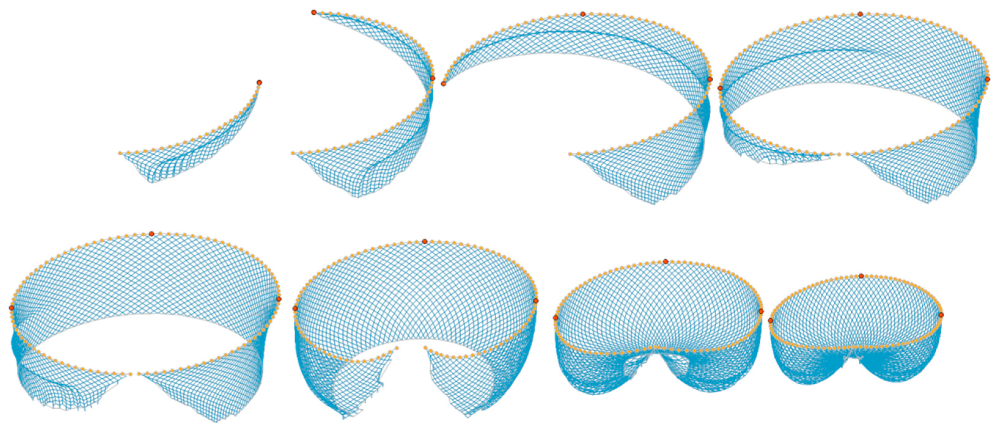
The entire shooting and pursing time of the computation required 15 and 30 min, respectively. As a case of simulation in static water, the wall of netting vertically spread to achieve the expected maximum working depth before pursing started. Further subject to towing tension of the seiner, a semi-ellipsoid encirclement was gradually formed, accompanied by the circular float line shrinking and transmuting into a heart shape (
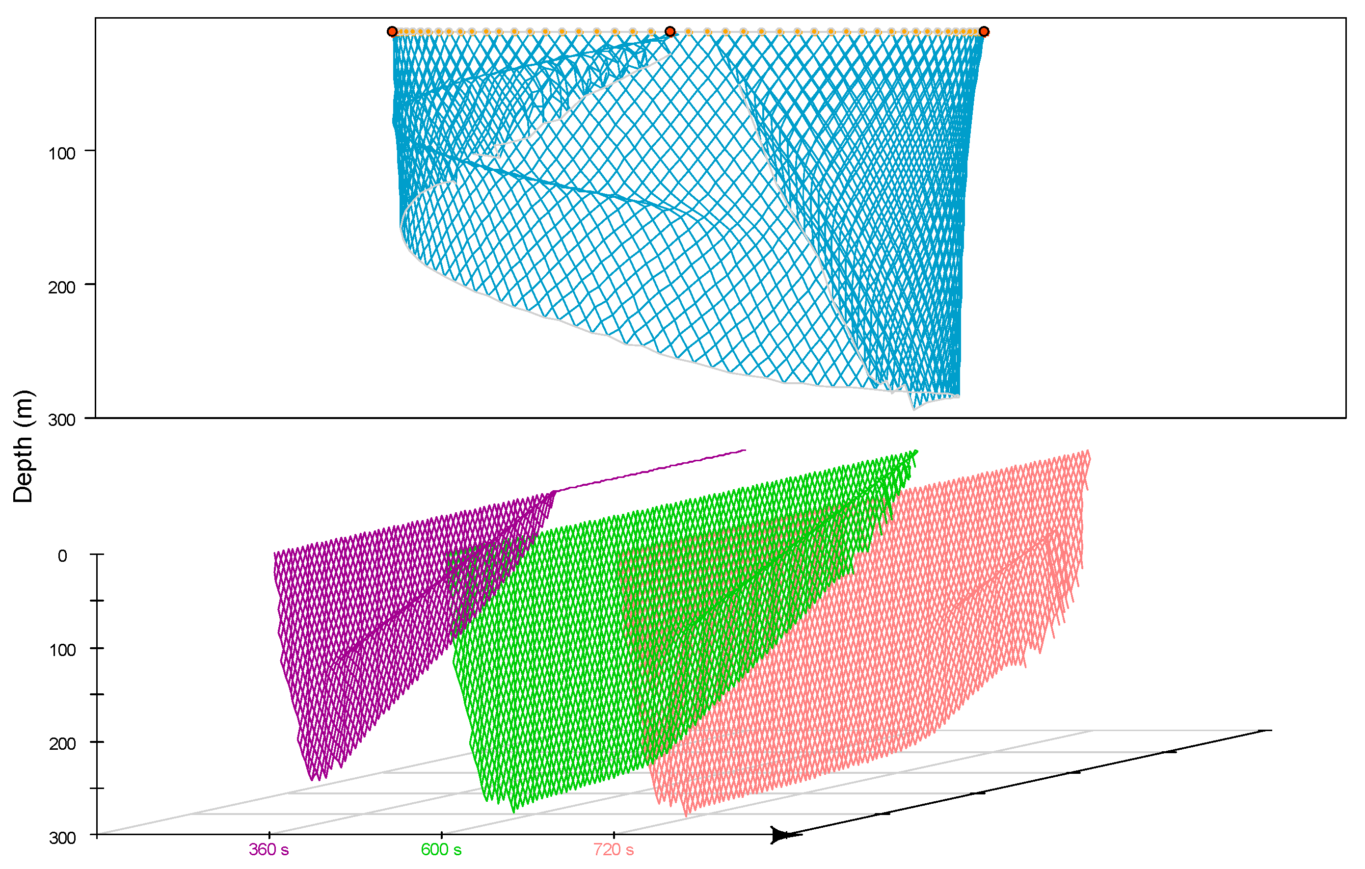
Figure 3). The lead line on the bunt side was at the farthest at nearly 300 m, and the rearward was getting increasingly shallower as shooting finished (equivalent to 600 s, Figure 4 top). The latter half part experienced net bundling, where the central section of netting received less sufficient deployment. At 360 s during shooting, the majority of netting was under inadequate extension. At 120 s after pursing, however, almost three-quarters of the lead line touched its terminal depth (
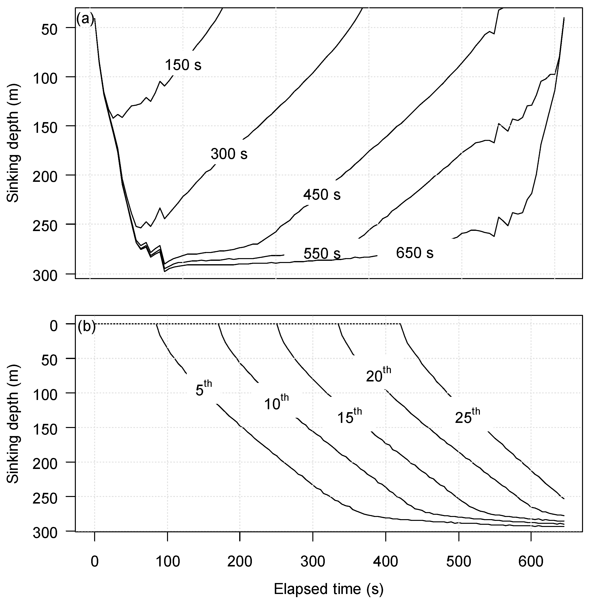
Figure 4 bottom). The detailed behavior of the lead line without flow interference is shown in Figure 5a for the vertical configuration at different time phases, and Figure 5b for the different sections depicting their continuous sinking process.
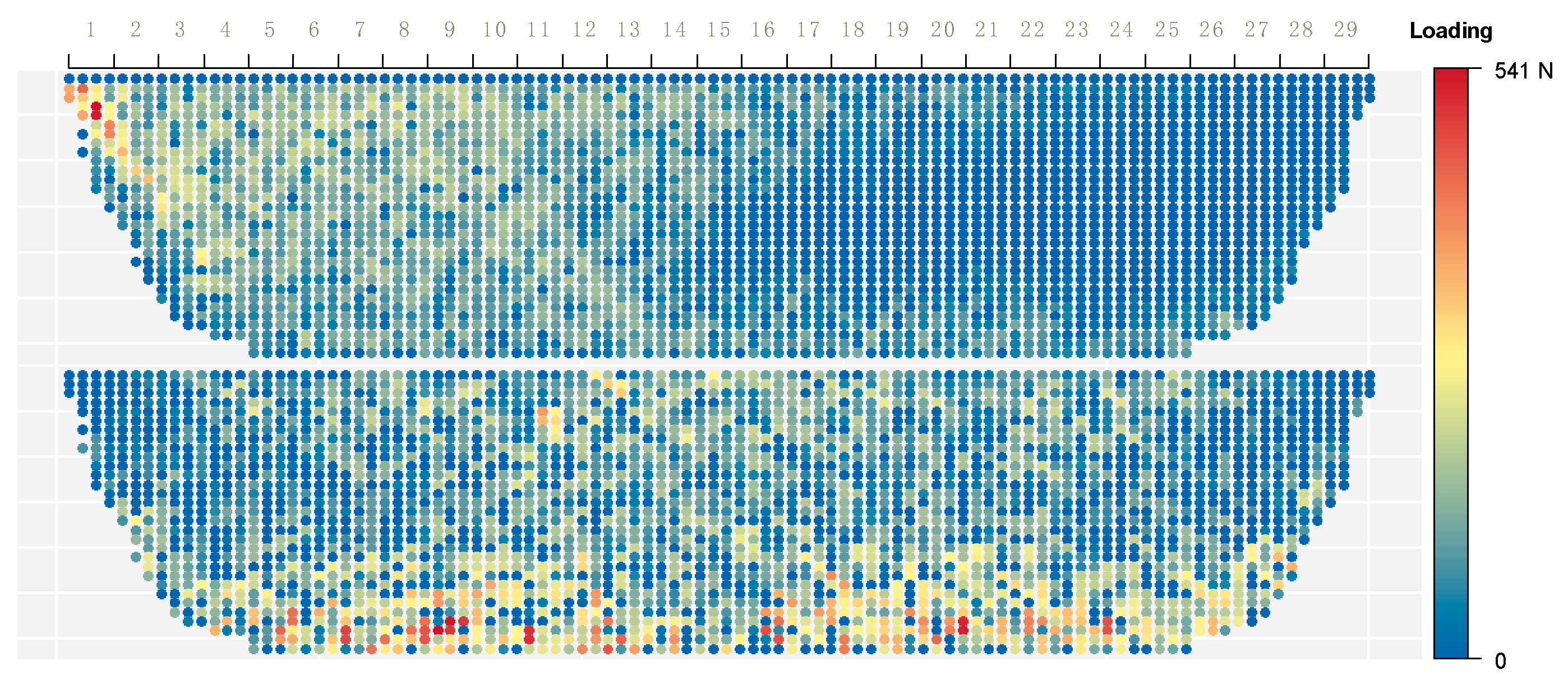
There were 29 strips of netting panels for the overall layout from the bunt to main body in the simulation. Load distribution on each knot showed that at the end of shooting (Figure 6 top), high load areas concentrated in the bunt with a maximum loading of 541 N, followed by the 3rd to 15th strips of the main body, as well as the lower edge along the lead line. From the 16th strip, they were less likely to suffer high loads, except near the bottom. As a result of the hauling force of the purse line during the pursing phase, high load regions spread dominantly at the low edge along the lead line and transmitted upward to the upper main body, with less loads at the two extremities (Figure 6 bottom).
In the seven cases where currents of different directions were applied, an assessment of the validation of simulation results was made by comparing them with the standardized results from the GLM model for the field measurements on the maximum sinking depth of the middle part of the lead line (Table 3). Underestimation was indicated for five cases, excluding case 2 (two-layers shear current) and case 4 (net mouth down the current). Large relative average errors exceeding 10% (over 30 m in absolute difference) appeared in those sets where the net mouth was either down the current or against the current, such as cases 2 (15.82%), 3 (13.81%), and 4 (15.40%). There was a close match for the rest of the cases, especially for case 7 (0.86%), that is, shooting in static water.
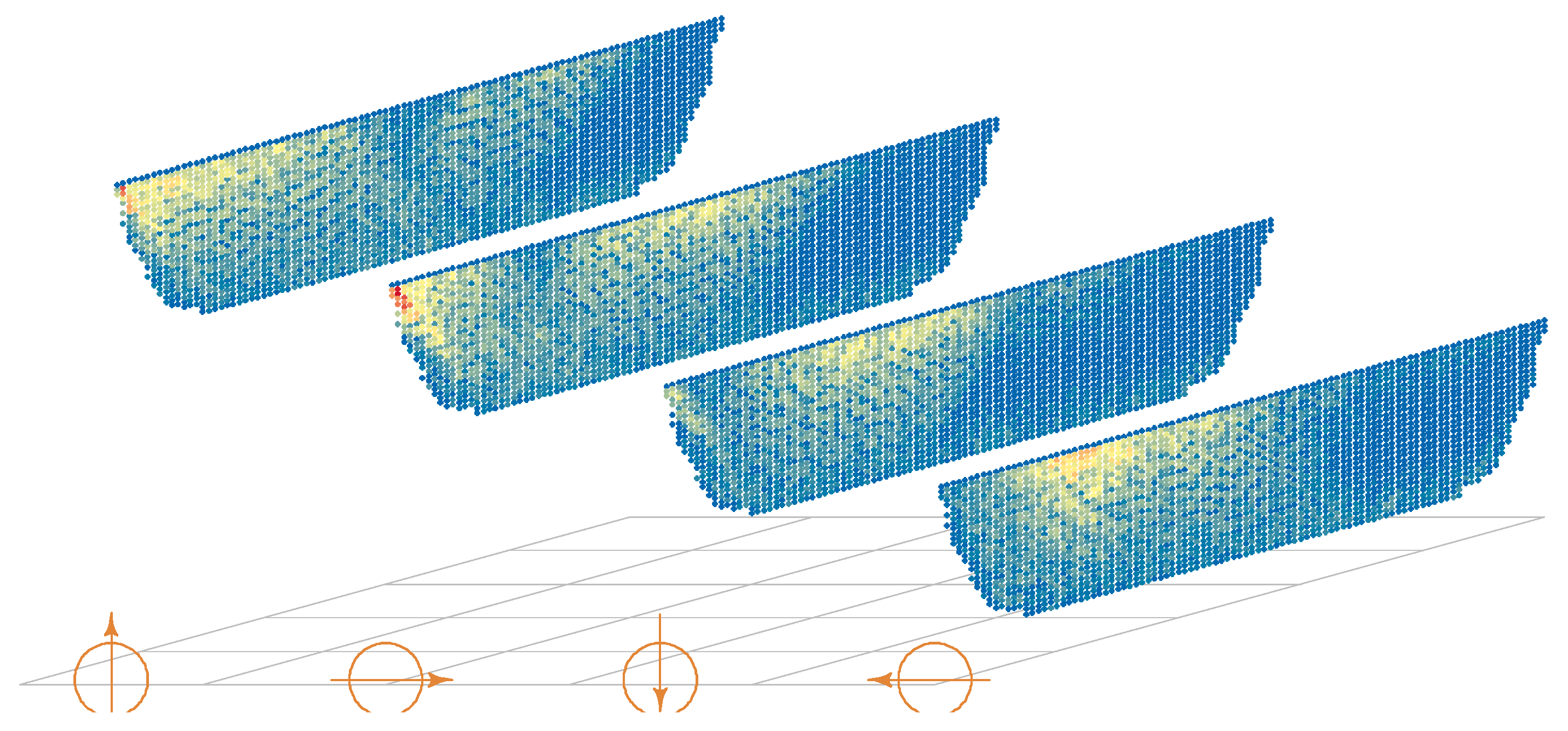
When 0.4 Kn of steady current was applied in the entire water column, we examined net shape and dynamic changes for four shooting patterns on the basis of current direction relative to the orientation of net mouth: 0 (counter-set), 90 (right-cross-set), 180 (forward-set), and 270 degrees (left-cross-set) (Figure 7). In the counter-set, high load was located at the upper area spanning from the bunt to around the 11th strip of the main body, followed by a later section of the main body. The middle section of the net was subjected to less load. The right-cross-set showed higher load in both the bunt and middle upper section. On the contrary, the highest tension for the left-cross-set was between the bunt and middle upper section. Forward-set experienced the lowest load among all the shooting patterns, mostly distributed in the 10th to 16th strips close to the central part of the net. For those two modes of current in the opposite direction (either counter-set to forward-set, or left-cross-set to right-cross-set), the load distributions were always mutually complementary.
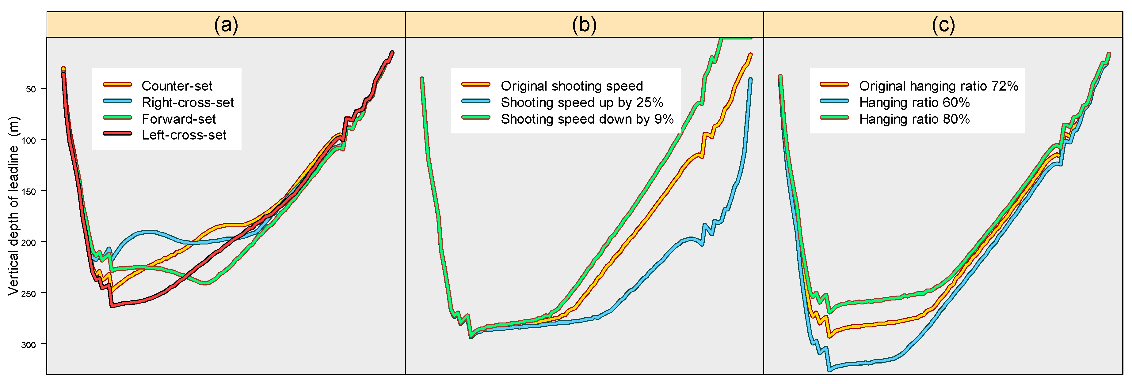
Vertical depth configurations of the lead line for different patterns at the end of the shooting are shown in Figure 8a. Left-cross-set provided better sinking behavior with the central part of the net approaching the depth of 260 m over the other three types of sets. In comparison, the right-crossing-set resulted in a maximum depth of no more than 220 m, particularly the central part of the lead line, which seemed to have been suppressed during the course of sinking. Counter-set had considerable sinking in the anterior part of the lead line close to the bunt side, but gradually got shallower toward the wing end. In contrast, forward-set produced more uniform sinking, resulting in a large proportion of lead line at a depth around 240 m.
Comparison of sinking depth at the normal shooting speed with that increased by 25% and that reduced by 9% showed that a higher shooting speed would contribute to greater sinking depth of the lead line at the end part (Figure 8b). The simulation of three types of nets with the average hanging ratio of 72% (normal, currently in common use), 60%, and 80% revealed that the net with a smaller hanging ratio would sink to a greater depth (Figure 8c).
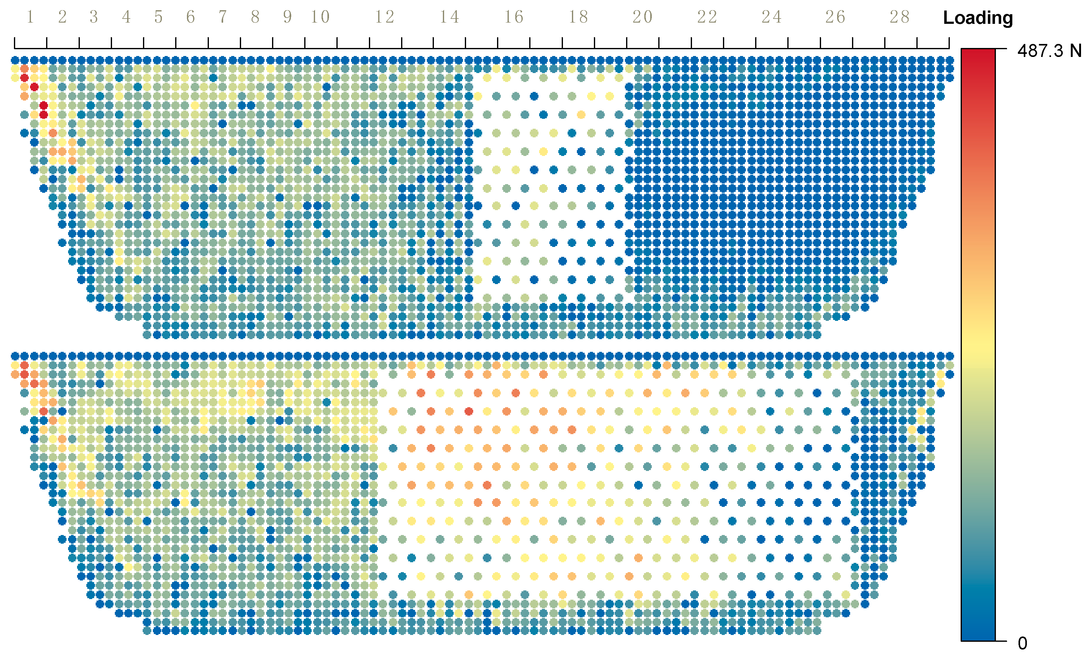
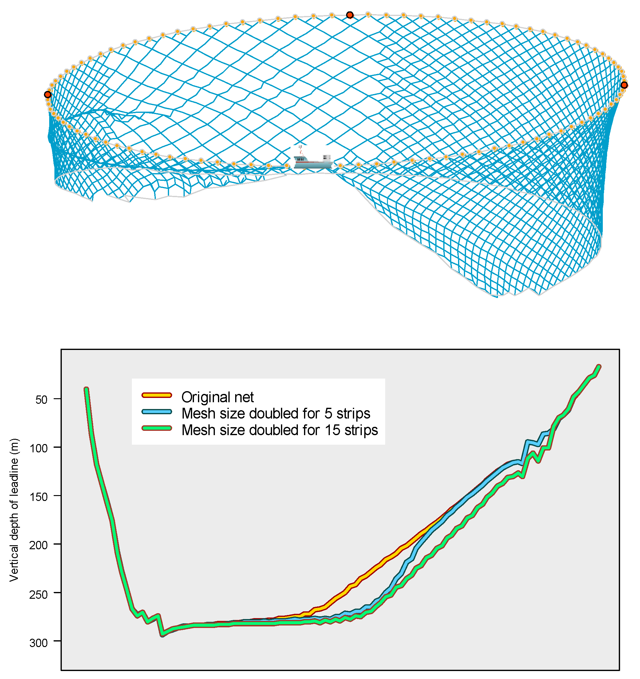
In order to evaluate the impact of larger mesh size on load-bearing and sinking performance, two alternatives were simulated: substituting the original mesh with a double-sized mesh with the same twine diameter across five successive from the 15th to 19th strips, or 15 strips from the 12th to 26th strips. For the first alternative, the bunt was found to be under strong load with maximum loading of 487.3 N. In addition, the replaced area was also a subset of the sub-heavy loading area covering from the 6th to 19th strips of the main body (Figure 9 top). In comparison, the second alternative displayed broader high-stress regions, including the bunt and strips 12 to 20 (Figure 9 bottom). However, lower mesh density as a result of using a larger mesh size reduced water resistance, which significantly accelerated the sinking of the lead line in the area (Figure 10).

4. Discussions

Both field measurements and model experiments are technically challenging in the observation of tuna purse seines owing to their large scale. A critical question is whether a model experiment based on the similarity criterion would provide dependable results (e.g., net shape and acting force) under which a scale effect is still unknown [
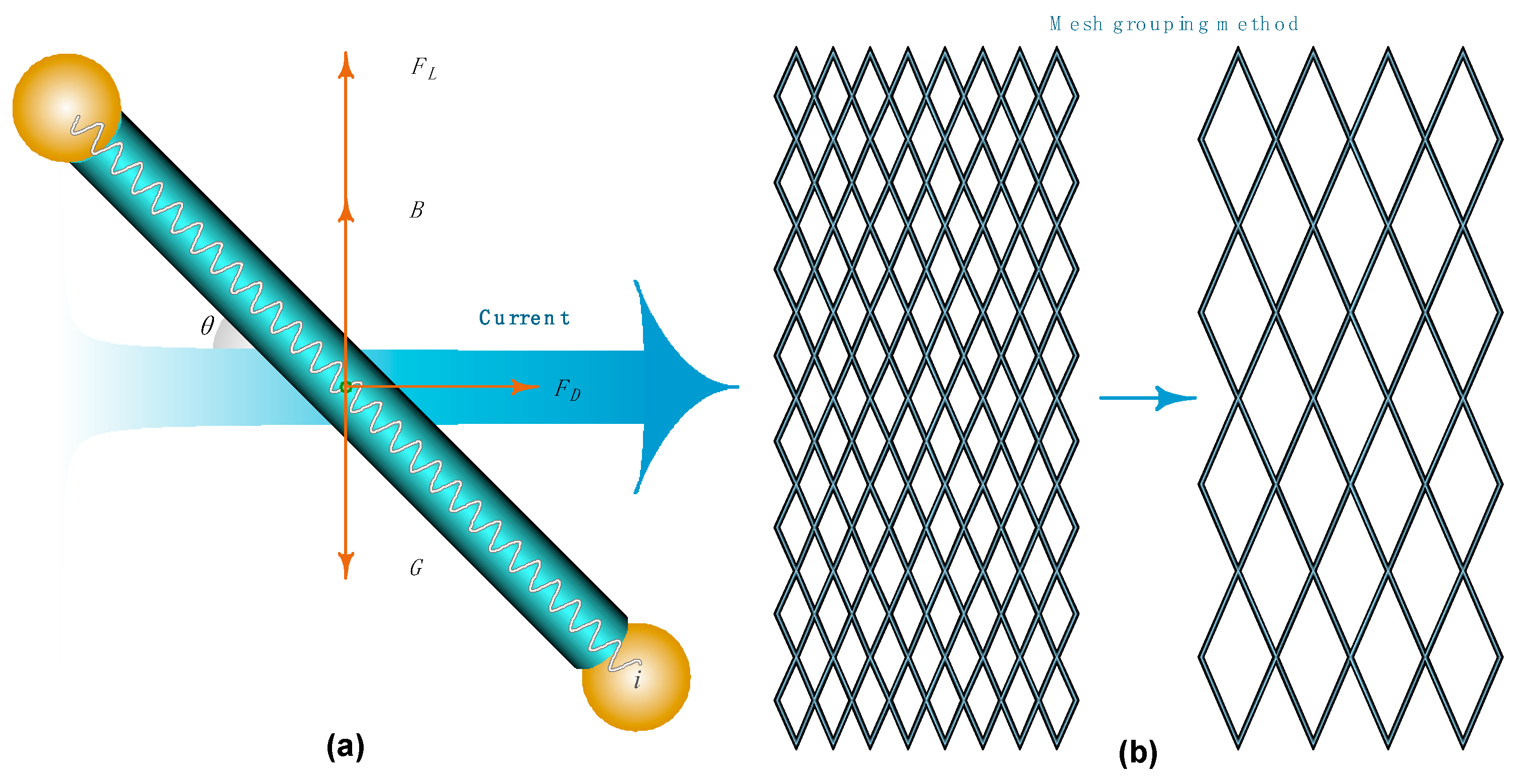
20]. As an alternative approach, we adopted numerical simulation to investigate the overall geometry and dynamics changes under the interference of different flows and design modifications. As accurate results of the simulation are highly dependent upon accurate estimates of fluid forces, hydrodynamic coefficients of prototype material were tested in this study, which consolidated the Reynold’s number, attack angle, and solidity ratio into the integrated empirical formulae. This further improved the understanding of the force of fluid passing through the netting on the basis of previous studies by taking into account the dual effects of the solidity ratio associated with the attack angle. Positive correlations dominated in the dependence of drag coefficient at high attack angles, while negative correlations dominated at low attack angles. We also provided a separate fit concerning netting parallel to currents in this case where the “shadow effect” achieves the maximum. However, when the netting falls into low attack angles (ca. within 20 degrees) relative to the incoming flow, downstream strands suffering the masking from upstream ones will be subjected to less fluid force, thus leading to decreasing drag coefficients. Owing to the limitation of experiment protocol, we were unable to obtain a more accurate empirical coefficient at a low attack angle, which may prevent our model from further improvement in the accuracy of prediction.
Considering tremendous mesh units of a large dimension prototype (billions of meshes for a tuna purse seine), the simulation of physical fishing gear is almost impossible to realize owing to the limitation of computer memory and lengthy runtime. The mesh grouping method was commonly applied to merge a number of meshes into one, so as to compose a lower-density equivalent net on the premise of maintaining consistent dominant forces [22,23]. The purpose of mesh grouping is to make the numerical simulation more efficient by reducing the computation time and loads, as well as maximally reducing the difference of the shape, force, and motion between the prototype and equivalent net. Previous studies proposed the constancy of a strand’s projected area and volume and derived different equivalent diameters to maintain the same total hydrodynamic force and mass [21]. On this basis, we further refined the mesh grouping method by introducing the compensation coefficient to distinguish the density of netting material between the prototype and equivalent net. This method solves the difficulty arising from the fact that the dominant forces for gear moving in the water, that is, hydrodynamic force and gravity, could not be maintained consistently simultaneously before and after grouping, and thus has more advantages over previous methods in the precise prediction of gear deformation and sinking.
Simulation results on the maximum depth of the middle part of lead line revealed over 30 m difference from that predicted by the GLM model based on field measurement for cases 4, 3, and 2, corresponding to forward-set, counter-set, and mixed two-layers shear current set, respectively. Those sets shared a common feature that the middle part of the net was almost normal to the current, revealing that improvement of hydrodynamic coefficients was still needed for our model. It is, however, commonly believed that the GLM model inherently has forecasting bias owing to its assumption of linear dependence between the sinking depth and current direction. Furthermore, the physical model idealized and simplified the actual condition, where some details were not always taken into consideration. For example, the current velocity imposed in the simulation was assumed to be a uniform averaged value, as opposed to varying current profiles from surface to deep layer in the field, which contribute to more complicated deformation of gear. As a simplified net structure, the model only constructed a general shape with tapered conformation in two wing ends and a consistent hanging ratio, while it was unable to fully reproduce the real prototype. In the process of operation, in the bundle part of the unfolded net, it was assumed that every mesh bar suffered completed fluid force, neglecting the fact that the sagging panels stack up and experience less drag. In addition, the solidity ratio was considered as a constant, while it underwent dynamic changes of low-to-high in the process from shooting to pursing.
The layout of the seine net is a meticulous assemblage of multi-panels that needs to give consideration to both how to minimize the net volume and to ensure integrity under uneven strains. In general, the bunt has the smallest mesh size of around 90 mm, but with thicker net twine; its size is usually reduced from the float line until close to the lower edge, where thicker twines are used in order to bear weight. Horizontally, there is successive transition by gradually increasing the mesh size and decreasing the twine diameter from the bunt to the main body. Simulation provided some insights into loading dynamics of netting planes over the operational period. High-load regions were located at the first half section in the shooting process, of which the bunt received the most tension. The entire lower region close to the lead line suffered higher loads during pursing, whereas the back wing sections were always less likely to suffer high loads. Therefore, it is suggested that netting panels with thicker twine and smaller mesh sizes should be used in those high-loading regions to ensure the firmness of the system.
Previous studies reported the effect of flow on the net geometry. When imposing 1 knot flow, the shape of net can measurably deform [18]. Through further consideration of complicated flow fields, another simulation case depicted that the net operating across a great water depth with non-uniform multilayer flow suffers from disordered geometry [19]. However, it has so far received much less concern about mechanics and characteristics of interfering factors from the orientation of the current relative to the net. Our results showed that the part away from the bunt had less tension for all cases of current directions (see Figure 7). Load distributions were mutually complementary for any two types of sets in relation to the opposite current: convex sections of net circles to which the current headed were always under a high load, whereas concave sections were almost stress free. The simulation results suggest that left-cross-set would provide the best sinking performance with the central part approaching the greatest depth of up to 260 m (Figure 8a). We also found that the forward-set contributed to more even sinking of the central part of the net, in contrast to dramatic variations in the depth of lead line in the counter-set, which was similar to Zhou et al. [8], who observed in a model experiment a curving inward and outward lead line configuration for forward-set and counter-set, respectively. In practice, judgment of shooting bearing relative to current direction in advance is of vital importance to the manipulation of the purse seine net. Forward-set may lead to the net drifting towards the underside of the seiner, while counter-set may cause increasing tension of the purse line. In contrast, right/left-cross-set may be the preferred operative mode, with the latter additionally conducive to the sinking.
Shooting speed was proven to be important for controlling the grounding of the seine. Rapid setting to finish the net circle in time can prevent the net from touching the sea-bed [21]. In open-sea areas with great depth, higher shooting speed can reduce the restriction of the boat to the part of the net just released from the boat, which would contribute to more uniform sinking of the net. Additionally, the choice of hanging ratio should reconcile the netting volume, sinking performance, and strand tension. An averaged hanging ratio of 0.72 in the main body is commonly used in Chinese tuna purse seines. Although the results showed that the hanging ratio of 0.6 would be more preferable for faster sinking, a decreasing hanging ratio will increase the amount of netting material. In terms of costs, the hanging ratio of 0.707 can provide the highest utilization of net panels, as well as a minimum amount of material at a certain dimension of gear.
Chinese tuna purse seine fleets setting productively on free-swimming schools have only taken around 40% of their total sets, resulting in heavy reliance on sets around fish aggregating devices (FADs). In response to increasingly restrictions on FADs sets by different regional fisheries management organizations (RFMOs), developing fishing strategies and operational methods that improve success rates and catch efficiency would encourage shifts to fish on free-swimming schools. Sinking velocity is considered as one of the most important parameters for successfully targeting free-swimming schools. Large sized meshes (usually larger than 300 mm) increase sinking and have been reported to increase the probability of success [20,24]. However, use of large-mesh netting should be taken conservatively as it may increase the vulnerability of strands. This study evaluated two options of large-meshed panels. Despite greater improvement in sinking depth with 15-strip large mesh options, there is an excessive risk in terms of the broader high-stress regions. By contrast, a 5-strip large mesh alternative would be preferable with the compromise of reasonable sinking velocity improvement and low mesh loads.

5. Conclusions

In the study, we employed the lumped mass method coupled with the tank tests of hydrodynamic coefficients to rebuild the underwater dynamic geometry of tuna purse seines during operation. A mesh grouping method was developed in order to efficiently make calculations based on different twine diameters and densities of netting material between a prototype and equivalent net.
Loading distribution dynamics suggested that the highly centralized region located at the first half section in the shooting process, especially for the bunt experiencing highest loads. During pursing, however, the entire lower region close to the lead line suffered higher loads, as opposed to less loads exerted on the back wing. Load distributions were often mutually complementary in the case of any two scenarios of opposite currents. In other words, convex sections of the net circle to which the current headed were under high load, whereas concave sections were almost stress free.
Simulation results suggested that the left-cross-set obtained the best sinking performance among all set types. Rapid shooting can contribute to deeper sinking for the lead line that is posteriorly released and will thus notably promote more balanced sinking. A reduced hanging ratio was a preferable alternative to faster sinking. Two alternatives of using large-mesh panels suggested that 5-strip double-size mesh panels would produce more balanced benefits compared with the 15-strip alternative owing to its potential high risk of strand vulnerability.

Author Contributions

Conceptualization, C.Z., L.X., F.H. and P.H.; Data curation, F.H. and T.K.; Funding acquisition, C.Z., L.X., X.W. and R.W.; Investigation, C.Z., H.T., F.H. and S.D.; Methodology, C.Z., L.X., T.K., R.W. and S.D.; Validation, C.Z., H.T. and X.W.; Writing – review & editing, C.Z., L.X. and P.H.

Funding

This research was done through financial support from the National Natural Science Foundation of China (No. 41806110, 41606110, 31902426, and 41506151); Shanghai Sailing Program (19YF1419800); and the Social Development Project of Zhejiang Public Welfare Technology Research (No. 2016C33083).

Conflicts of Interest

The authors declare no conflict of interest.

References

  1. Hare, S.R.; Harley, S.J.; Hampton, W.J. Verifying FAD-association in purse seine catches on the basis of catch sampling. Fish. Res. 2015, 172, 361–372. [Google Scholar] [CrossRef] [Green Version]
  2. Groeneveld, R.A.; Quaas, M.F. Promoting selective fisheries through certification? An analysis of the PNA unassociated-sets purse seine fishery. Fish. Res. 2016, 182, 69–78. [Google Scholar] [CrossRef]
  3. Brouwer, S.; Pilling, G.; Hampton, J.; Williams, P.; McKechnie, S. The Western and Central Pacific Tuna Fishery: 2015 Overview and Status of Stocks; Pacific Community: Noumea, New Caledonia, 2016; pp. 1–46. [Google Scholar]
  4. Itano, D.G. Super Superseiner. In Proceedings of the 15th Standing Committee on Tuna and Billfish, Honolulu, HI, USA, 22–27 July 2002. [Google Scholar]
  5. Ben-Yami, M. Purse Seining—FAO Fishing Manuals; Fishing New Books: London, UK, 1994; pp. 1–406. [Google Scholar]
  6. Hall, M.; Roman, M. Bycatch and Non-Tuna Catch in the Tropical Tuna Purse Seine Fisheries of the World; FAO Fisheries and Aquaculture Technical Paper No. 568; FAO: Rome, Italy, 2013; pp. 1–249. [Google Scholar]
  7. Zhou, C.; Xu, L.; Tang, H.; Wang, X. In-situ dynamics of tuna purse seine deployment in various operations and currents. Fish. Sci. 2015, 81, 1003–1011. [Google Scholar] [CrossRef]
  8. Zhou, C.; Xu, L.; Hu, F.; Kumazawa, T. The kinetic deformation of tuna purse seine: A model experiment on different shooting patterns at uniform current. Fish. Res. 2015, 169, 18–25. [Google Scholar] [CrossRef]
  9. Kim, S.J.; Park, J.S. Characteristics of the motion of a purse seine. (1) The sinking behaviour of a model purse seine with different netting materials. Bull. Korean Soc. Fish. Technol. 1995, 31, 362–371. [Google Scholar]
  10. Shin, J.; Imai, T.; Fuwa, S.; Ishizaki, M. A model experiment on the characteristics of fishing gear of lampala net. Nippon Suis. Gak. 1998, 64, 759–767. [Google Scholar] [CrossRef]
  11. Katiandagho, M.E.; Imai, T. Fundamental studies on the fishing efficiency of purse seine. Mem. Kagoshima Univ. Res. Center S. Pac. 1985, 6, 229–247. [Google Scholar]
  12. Balash, C.; Colbourne, B.; Bose, N.; Raman-Nair, W. Aquaculture net drag force and added mass. Aquacult. Eng. 2009, 41, 14–21. [Google Scholar] [CrossRef]
  13. Swift, M.; Fredriksson, D.; Unrein, A.; Fullerton, B.; Patursson, O.; Baldwin, K. Drag force acting on biofouled net panels. Aquacult. Eng. 2006, 35, 292–299. [Google Scholar] [CrossRef]
  14. Tsukrov, I.; Drach, A.; DeCew, J.; Swift, M.R.; Celikkol, B. Characterization of geometry and normal drag coefficients of copper nets. Ocean Eng. 2011, 38, 1979–1988. [Google Scholar] [CrossRef]
  15. Zhan, J.M.; Jia, X.P.; Li, Y.S.; Sun, M.G.; Guo, G.X.; Hu, Y.Z. Analytical and experimental investigation of drag on nets of fish cages. Aquacult. Eng. 2006, 35, 91–101. [Google Scholar] [CrossRef]
  16. Shimizu, H.; Mizukami, Y.; Kitazawa, D. Experimental study of the drag on fine-mesh netting. Aquacult. Eng. 2018, 82, 80–85. [Google Scholar] [CrossRef]
  17. Lee, C.W.; Lee, J.H.; Cha, B.J.; Kim, H.Y.; Lee, J.H. Physical modeling for underwater flexible systems dynamic simulation. Ocean Eng. 2005, 32, 331–347. [Google Scholar] [CrossRef]
  18. Kim, H.Y.; Lee, C.W.; Shin, J.K.; Kim, H.S.; Cha, B.J.; Lee, G.H. Dynamic simulation of the behavior of purse seine gear and sea-trial verification. Fish. Res. 2007, 88, 109–119. [Google Scholar] [CrossRef]
  19. Kim, Y.H.; Park, M.C. The simulation of the geometry of a tuna purse seine under current and drift of purse seiner. Ocean Eng. 2009, 36, 1080–1088. [Google Scholar] [CrossRef]
  20. Hosseini, S.A.; Lee, C.W.; Kim, H.S.; Lee, J.H.; Lee, G.H. The sinking performance of the tuna purse seine gear with large-meshed panels using numerical method. Fish. Sci. 2011, 77, 503–520. [Google Scholar] [CrossRef]
  21. Riziotis, V.A.; Katsaounis, G.M.; Papadakis, G.; Voutsinas, S.G.; Bergeles, G.; Tzabiras, G.D. Numerical and experimental analysis of the hydroelastic behavior of purse seine nets. Ocean Eng. 2013, 58, 88–105. [Google Scholar] [CrossRef]
  22. Tsukrov, I.; Eroshkin, O.; Fredriksson, D.; Robinson, S.M.; Celikkol, B. Finite element modeling of net panels using a consistent net element. Ocean Eng. 2003, 30, 251–270. [Google Scholar] [CrossRef]
  23. Bessonneau, J.S.; Marichal, D. Study of the dynamics of submerged supple nets (applications to trawls). Ocean Eng. 1998, 25, 563–583. [Google Scholar] [CrossRef]
  24. Takagi, T.; Miyata, S.; Fusejima, I.; Oshima, T.; Uehara, T.; Suzuki, K.; Nomura, Y.; Kanechiku, M.; Torisawa, S. Effect of mesh size on sinking characteristics of purse seine net: A parametric study by numerical simulation. Fish. Eng. 2014, 51, 11–19. [Google Scholar]
Figure 1. Illustrated interpretation. (a) Mechanical compositions of individual net twine in the flow. (b) Mesh grouping method. Netting of the mesh numbered 8 × 8 was grouped into equivalent nets with the grouping ratio r = 2 with constant mesh size.
Jmse 07 00405 g001
Figure 2. The net plan of the purse seine gear with 29 strips of netting panels. K is a measure of length equal to 1.515 m. Letters indicate the identifier of net panels with different mesh sizes or twine thicknesses.
Jmse 07 00405 g002
Figure 3. Snapshots from the sequential simulation of behavior of tuna purse seine from shooting to pursing in stationary water.
Jmse 07 00405 g003
Figure 4. Front view of the seine net in stationary water, showing the instant sinking depth at the end of shooting (top), and the horizontally unfolded plane for three typical points in time after shooting started: 300 s (during shooting, purple), 600 s (end of shooting, green), and 720 s (during pursing, orange) (bottom).
Jmse 07 00405 g004
Figure 5. Sinking behavior without flow interference. (a) Vertical configuration and depth of lead line at time phases of 150 s, 300 s, 450 s, 550 s, and 650 s. (b) Changing sinking depth with elapsed time for the 5th, 10th, 15th, 20th, and 25th strips.
Jmse 07 00405 g005
Figure 6. Load distribution at the knots of unfolded seine net made up of 29 strips, at the end of shooting (top) and during pursing (bottom). The averaged breaking strength of strands was measured to be ca. 1700 N.
Jmse 07 00405 g006
Figure 7. Load distribution (refer to color key in Figure 4) under four scenarios of current directions relative to southward net mouth at a steady current of 0.4 Kn in the entire water column, from left to right, counter-set, right-cross-set, forward-set, and left-cross-set.
Jmse 07 00405 g007
Figure 8. Vertical depth of the entire lead line at the end of shooting. (a) Under four types of settings at 0.4 Kn uniform current: counter-set, right-cross-set, forward-set, and left-cross-set. (b) Under different shooting speeds: normal, 1.25 times the normal, and 0.91 times the normal. (c) Three types of net with different average hanging ratio: 72% (normal), 60%, and 80%.
Jmse 07 00405 g008
Figure 9. Load distribution at the end of shooting of two alternative nets with the mesh size doubled from the original mesh size of 260 mm across five successive strips from the 15th to 19th strips (top) and 15 strips from the 12th to 26th strips (bottom). The averaged breaking strength of strands was measured to be ca. 1700 N.
Jmse 07 00405 g009
Figure 10. Three-dimensional shape for the net (top panel, five-strip large mesh net only) and the vertical depth of the entire length of the lead line at the end of shooting (bottom panel) for the original net, and the alternative net with its mesh size doubled for 5 strips and 15 strips.
Jmse 07 00405 g010
Table 1. Specifications for net panels for different parts of the purse seine.
SectionSub-SectionMaterialTwine Diameter (mm)Mesh Size (mm)Mesh (T × N)Number of Panels
AA1Nylon6.0135120 × 101
A2240 × 101
A3380 × 101
A4540 × 101
A5240 × 101
A6180 × 101
A7120 × 101
A8560 × 1030
A9560 × 1030
B Nylon5.790840 × 1222
CC1Nylon4.490840 × 1223
C2840 × 1222
DD1Nylon4.1590840 × 1223
D2840 × 1224
EE1Nylon3.890840 × 1224
E2840 × 1223
E3840 × 1221
FF1Nylon3.790840 × 1223
F2840 × 1224
F3840 × 1221
GG1Nylon3.4590840 × 1228
G2840 × 1224
HH1Nylon3.45105720 × 1001
H2720 × 1001
H31440 × 1001
H42880 × 1001
II1Nylon2.7105720 × 1003
I2720 × 1001
I31440 × 1001
I41440 × 1001
JJ1Nylon2.4105720 × 10014.5
J2720 × 10018.5
J3720 × 10012
KK1Nylon2.4210360 × 509.5
K2360 × 5023.5
LL1Nylon2.4260290 × 80228
L2290 × 8011
L3290 × 8011
L4290 × 8010
M Nylon2.7210360 × 5021
NN1Nylon6.0300640 × 201
N2480 × 201
N3360 × 201
N4260 × 201
N5160 × 201
O Nylon3.7127600 × 8026
PP1Nylon2.7210360 × 5023
P2360 × 5025
QQ1Nylon2.4210360 × 5024
Q2360 × 5018
R Nylon3.45210360 × 5025
S Nylon3.7120630 × 5029
TT1Nylon2.4210360 × 1501
T2360 × 1501
Table 2. Specification for accessory components.
AccessoriesSpecificationDescriptor
FloatMaterialEthylene Vinylacetate Copolymer
Buoyancy500 N m−1
Float lineMaterialNylon
Diameter20 mm
Total length1619 m
Sinking chainMaterialIron
Bar diameter12.7 mm (1/2″) and 15.9 mm (5/8″)
Total length1960 m
Weight in water3.54 kg m−1 (1/2″) and 6.17 kg m−1 (5/8″)
Purse lineMaterialIron
Diameter26 mm
Total length2900 m
Purse ringMaterialIron
Number120
Weight in water Each 5.24 kg
Table 3. A comparison between the standardized maximum depths of the middle part of the lead line from the field measurement and those from simulation under seven cases. Relative average error ε is defined as the absolute value of difference between the model-predicted and simulation-based depth divided by model-predicted depth. GLM, generalized linear model.
Shooting Duration (s)Current Speed at 60 m (Kn)Current Speed for 120 m (Kn)Current Direction at 60 m (°)Current Direction at 120 m (°)Net Mouth Orientation (°)Predicted Depth by GLM (m)Simulated Depth (m)Relative Average Error ε
15000.40.4090180224.93213.525.07%
25000.40.41800180194.33225.0815.82%
35000.40.400180237.53204.7213.81%
45000.40.4180180180219.53253.3415.40%
55000.40.49090180228.53219.773.83%
65000.40.44545180233.03213.148.53%
75000000180255.38253.180.86%

