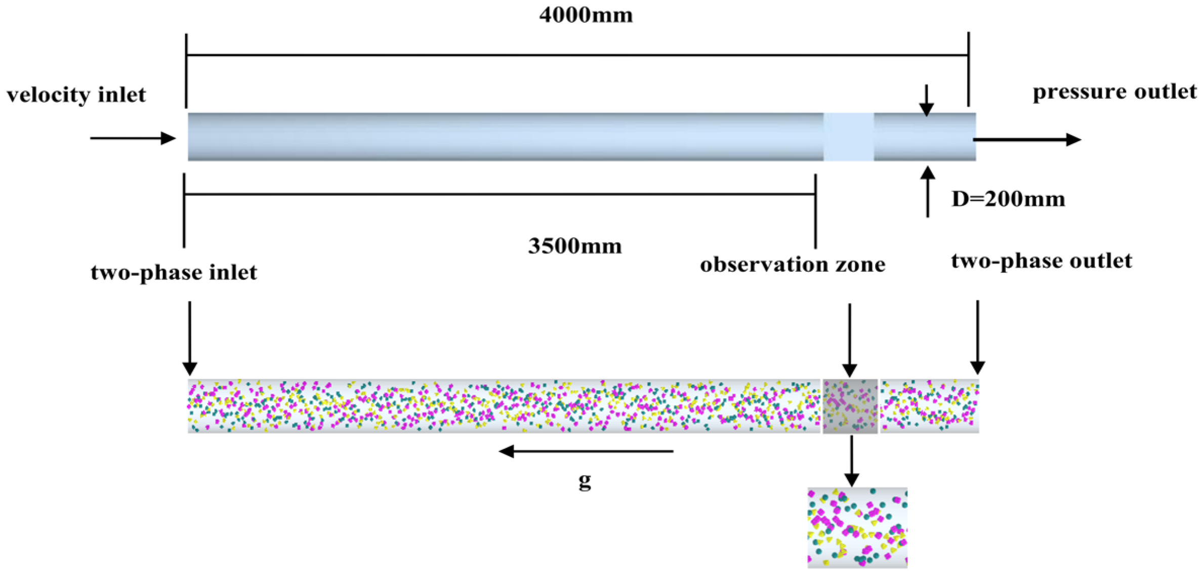
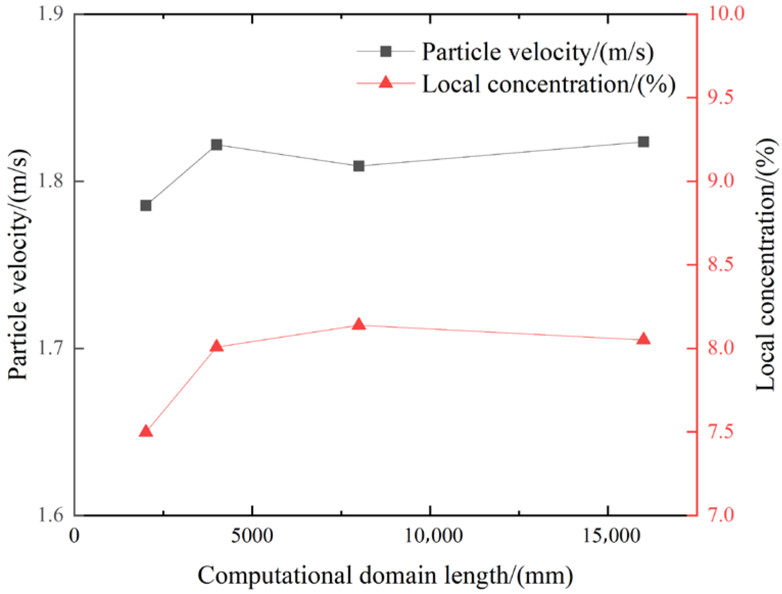
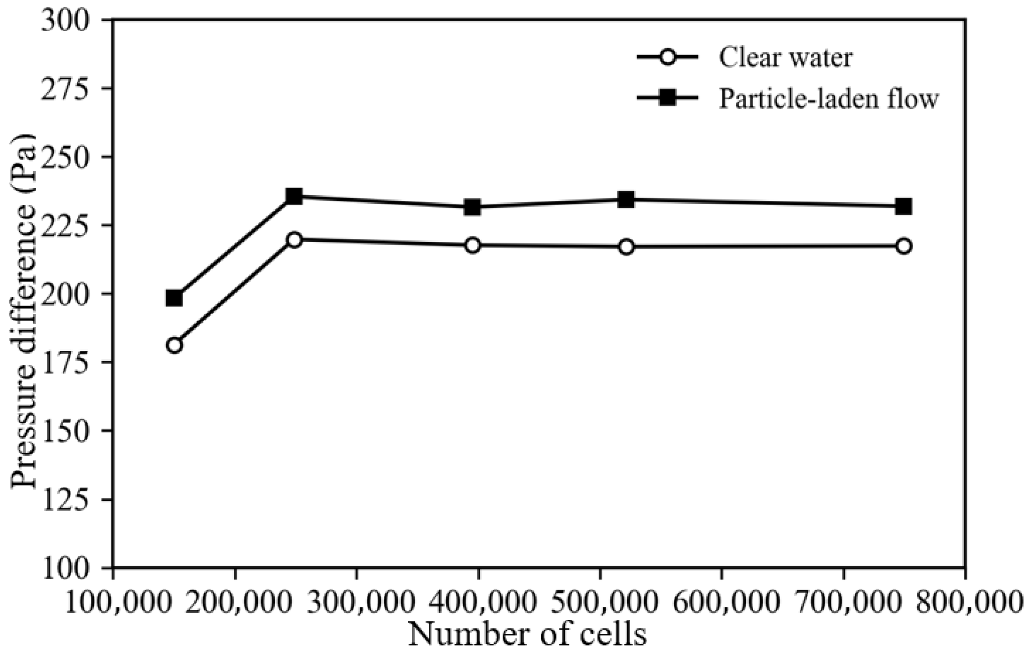
1. Introduction
With the progressive depletion of the grade of terrestrial mineral resources and the sustained increase in demand for strategic metals, the efficient exploitation of seabed mineral resources, such as deep-sea polymetallic nodules, cobalt-rich crusts, and polymetallic sulfides, has become a major research focus in the fields of marine engineering and resource utilization. As the core link connecting subsea mineral collection to surface support platforms in deep-sea mining systems, the vertical lifting system directly determines the continuous transport capacity of ore particles, overall system energy consumption, and operational safety [
1,
2]. Existing vertical transport schemes for deep-sea mining mainly include hydraulic lifting, pneumatic lifting, and their derivative forms. Among them, hydraulic pipeline lifting is widely regarded as one of the most promising technical approaches because of its relatively mature system configuration, strong conveying capacity, and high engineering feasibility [
3,
4]. However, deep-sea mining slurry generally constitutes a solid–liquid two-phase mixture characterized by high solids concentration, broad particle size distribution, and strong heterogeneity. The suspension, collision, aggregation, and redispersion of particles during long-distance transport in vertical pipelines substantially increase the complexity of the flow mechanisms and may induce local high-concentration retention, elevated pressure drop, and even pipeline blockage, thereby imposing more stringent requirements on the stable operation of the lifting system [
5,
6,
7,
8].
Extensive efforts have been devoted, both domestically and internationally, to the investigation of solid–liquid two-phase flow in deep-sea mining lifting pipelines through theoretical analysis, numerical simulation, and experimental research. Based on vertical lifting-pipeline models, Su et al. [
5], Dai et al. [
6], and Li et al. [
9] systematically examined motion characteristics, pressure distribution, and transport performance of deep-sea mineral particles within the pipeline, demonstrating that flow rate, particle concentration, and particle size are the key factors governing lifting performance. With respect to the transport mechanism of coarse particles in vertical pipelines, Zhao et al. [
10] established a velocity distribution model for coarse-particle slurry flow in vertical pipes. Huang et al. [
7], Zhang et al. [
11], and Chen et al. [
12] elucidated the fundamental transport behaviors of coarse particles from the perspectives of critical non-deposition velocity, critical suction velocity, and particle kinematics, respectively. Sun et al. [
13] further developed a probabilistic model for transport efficiency that incorporates particle size distribution. Meanwhile, Kaushal et al. [
14], Pedersen et al. [
15], and Jerez-Carrizales et al. [
16] provided comprehensive reviews of numerical simulation and flow-prediction methods for multiphase pipeline flow, offering important guidance for the modeling of complex multiphase transport in pipeline systems.
With the advancement in computational fluid dynamics and the discrete element method, CFD-DEM (Computational Fluid Dynamics–Discrete Element Method) coupling has gradually become an important tool for elucidating particle–fluid interactions in deep-sea mining systems. This method enables the simultaneous characterization of the evolution of the continuous-phase flow field and the collision, slip, and agglomeration behaviors of discrete particles, and has demonstrated strong applicability in studies of deep-sea mining lifting pipelines and key pumping components [
17,
18,
19,
20,
21]. In recent years, Yang et al. [
22] investigated the effects of feed concentration, particle gradation, and particle density on the transport characteristics in vertical pipelines; Wan et al. [
23] examined the two-phase flow behavior of coarse particles under forced-vibration conditions; Li et al. [
24] analyzed the conveying behavior of particles with wide particle size gradation in deep-sea vertical pipelines; and Wang et al. [
25] and Hu et al. [
26] further focused on the effects of irregularly shaped and non-spherical mineral particles on local concentration, flow stability, and transport efficiency. These studies have shown that significant coupling exists among particle shape, particle size distribution, and operating parameters, and that such interactions exert a non-negligible modulating effect on local flow-field structures and the spatial distribution of particles.
Although existing studies have provided an important theoretical foundation for vertical lifting in deep-sea mining, several limitations still remain in the current body of research. First, many previous investigations have focused on system-level schemes, internal flow within lifting pumps, or the influence of specific single factors [
27,
28], whereas systematic studies on the evolution of local concentration, variations in local flow rate, and particle distribution patterns of coarse-particle slurry during the initial mixing stage and early stabilization stage within vertical straight-pipe sections remain relatively limited. Second, although progress has been made in studies concerning particle size distribution, particle density, and non-sphericity effects, comparative analyses of key factors, including inlet velocity, feed concentration, particle size, and particle shape within a unified framework are still scarce, particularly regarding quantitative discussion aimed at engineering parameter selection. For coarse-ore particles generated after comminution in deep-sea mining operations, these parameters directly affect particle suspension capacity, collision frequency, the extent of local accumulation, and pipeline transport efficiency. Further investigation is therefore clearly warranted.
Accordingly, in this study, a CFD-DEM coupling approach within an Euler–Lagrange framework was employed to investigate a deep-sea mining vertical lifting pipeline. Focusing on the effects of inlet velocity, feed concentration, particle size, and particle shape, the variations in local concentration, local flow rate, and particle volume fraction distribution within the pipeline were systematically analyzed. On this basis, differences in particle transport behavior and mixing uniformity under various operating conditions were compared, the mechanisms by which key parameters influence vertical lifting performance were elucidated, and a theoretical basis was established for the subsequent parameter optimization, experimental design, and engineering application of deep-sea mining lifting systems.
2. Theory and Methods
2.1. Governing Equations
A CFD-DEM coupling approach within an Euler–Lagrange framework was employed to describe the solid–liquid two-phase flow of slurry in the vertical pipeline. The continuous seawater phase was treated as an incompressible Newtonian fluid, whereas the translational and rotational motions of the discrete ore particles were tracked using DEM. To account for the influence of particle spatial occupancy on the fluid flow, the continuous-phase volume
fraction was introduced, and the governing equations for the fluid phase can be written as follows [
29]:
where
denotes the Nabla operator;
is the fluid velocity within the pipeline (ms
−1);
is the fluid density (kgm
−3);
p is the pressure (Pa);
is the viscous stress tensor (Pa); and
is the particle–fluid momentum-exchange source term (N·m
−3), which characterizes the feedback of the discrete phase on the continuous phase.
The particles were treated as rigid bodies, and their translational and rotational motions are governed by Newton’s second law and the angular momentum equation, respectively [
30,
31]:
where
is the mass of the ore particle (kg);
is the particle velocity (ms
−1);
is the collision force acting on the particle (N);
is the hydrodynamic force exerted by the fluid on the particle (N);
is the moment of inertia of the ore particle (kgm
2);
is the angular velocity of the particle (rads
−1);
is the contact torque exerted on the particle by other ore particles (Nm); and
is the hydrodynamic torque acting on the particle due to the surrounding fluid (Nm).
It should be noted that the inertial effect of particle motion is inherently represented by the left-hand side of Equation (3), i.e., msdvs/dt, and is therefore not introduced as an additional independent force term in the present simulations.
2.2. Particle Force Models and Assumptions
In principle, particles undergoing unsteady motion in a solid–liquid flow may be subjected to multiple hydrodynamic contributions. However, not all of these contributions are necessarily activated as independent force models in a CFD-DEM simulation. In the present study, particle translation and rotation were solved by Newton’s second law and the angular momentum equation, respectively. Therefore, particle inertia is inherently accounted for by the acceleration term in Equation (3), rather than being treated as a separate external force. To avoid unnecessary repetition of force terms that have already been extensively discussed in previous studies, only the forces explicitly considered in the present simulations are described here, including gravity, fluid drag, Saffman lift, Magnus lift, fluid-induced torque, and particle–particle/particle–wall contact forces.
2.2.1. Gravity
Gravity is determined by the particle mass itself and can be expressed as follows [
30,
31]:
where
is the gravitational force acting on the particle (N);
is the particle diameter (m);
is the density of the ore particle (kgm
−3); and
is the gravitational acceleration (m
−2).
2.2.2. Fluid Drag
When particles move through a flow field, they experience resistance from the surrounding fluid, which constitutes the primary hydrodynamic force governing their transport behavior. The drag force can be expressed as follows [
30,
31]:
where
is the drag force acting on the particle (N);
is the drag coefficient;
is the fluid density (kg m
−3);
is the projected area of the ore particle (m
2);
is the local fluid velocity in the vertical pipeline corresponding to the particle-center position (m s
−1); and
is the velocity of the particle (m/s).
2.2.3. Saffman Force
Saffman force arises from the presence of a velocity gradient in the vertical pipe flow, and its effect becomes appreciable only when the ore particles are relatively large and the flow-velocity gradient is sufficiently strong. Its governing expression is given as follows [
30,
31]:
where
is the Saffman lift force acting on the particle (N);
y is the transverse coordinate (m); and
denotes the velocity gradient of the flow field (s
−1).
2.2.4. Magnus Force
When a body moves and rotates in a flow field, a lift force is generated, which alters its direction of motion. This force is referred to as the Magnus force. Its governing expression is given as follows [
30,
31]:
where
is the Magnus lift force acting on the particle (N);
is the angular velocity of the particle (rad s
−1); and
is the diameter of particle i (m).
The Saffman force is a shear-induced lift force associated with the local velocity gradient of the flow field. In a shear flow, the fluid velocities on the two sides of a particle are different, resulting in an asymmetric distribution of shear stress and pressure around the particle and thus producing a lateral lift force. By contrast, the Magnus force originates from particle rotation relative to the surrounding fluid. Its physical origin lies in the asymmetric pressure distribution caused by the combined effect of particle spin and translational motion. Therefore, the Saffman force is shear-induced, whereas the Magnus force is rotation-induced.
2.2.5. Contact Forces and Torque
In addition to the hydrodynamic forces, particle–particle and particle–wall interactions were considered through the Hertz–Mindlin (no slip) contact model, as described in
Section 3.4. The corresponding contact forces and torques were incorporated into the particle translational and rotational equations of motion.
2.3. CFD-DEM Method
To accurately characterize the solid–liquid two-phase flow behavior in the vertical lifting pipeline, a bidirectionally coupled CFD-DEM method was employed in the present study. The continuous seawater phase was solved using ANSYS Fluent 2023R1, whereas the discrete ore particles were tracked using EDEM. Within this Euler–Lagrange framework, the carrier fluid was treated as a continuous phase and the ore particles were treated as discrete bodies, allowing the simultaneous description of the evolution of the fluid flow field and the motion, collision, and transport behavior of particles.
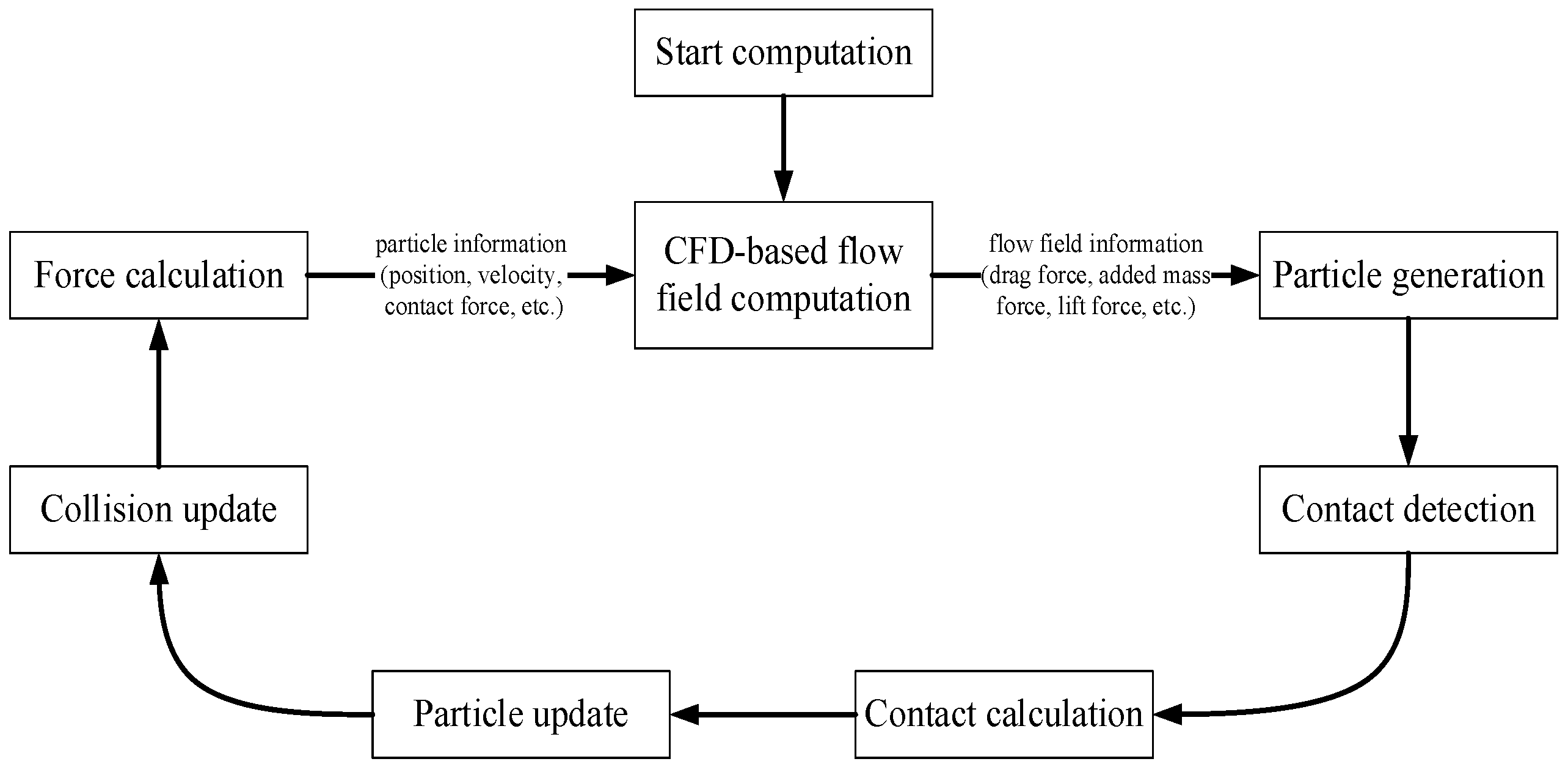
The coupling procedure is illustrated schematically in
Figure 1. At each coupling time step, the CFD solver first updated the local flow field and transferred the relevant flow information, including velocity, pressure, and velocity-gradient-related quantities, to the DEM solver. Based on these local fluid data, the hydrodynamic forces acting on the particles were evaluated. The DEM solver then performed particle motion integration, contact detection, and contact force calculation, and updated the particle positions, velocities, and rotational states. Subsequently, the particle information, such as particle distribution, velocity, and local volume fraction, was fed back to the CFD side to update the particle–fluid momentum-exchange source term and local phase distribution in the governing equations of the continuous phase. Through this repeated exchange of flow-field information and particle-state information, the bidirectional coupling between the continuous and discrete phases was achieved during the entire simulation process.
Within the present software implementation, particle inertia was inherently accounted for through Newton’s second law and was therefore not introduced as an additional independent force term. The hydrodynamic force models explicitly considered in the present simulations included fluid drag, Saffman lift, Magnus lift, and fluid-induced torque, while particle–particle and particle–wall interactions were modeled using the Hertz–Mindlin (no slip) contact model. In this way, the present CFD-DEM framework was able to capture both the influence of the fluid flow on particle suspension and transport and the feedback effect of the particle phase on the local flow structure.
Compared with one-way coupling, the present bidirectional CFD-DEM framework is more suitable for describing slurry transport in a vertical lifting pipe, where strong particle–fluid interaction, particle accumulation, and momentum exchange are essential features of the flow.
4. Analysis of Simulation Results
4.1. Effect of Inlet Velocity on Lifting Performance
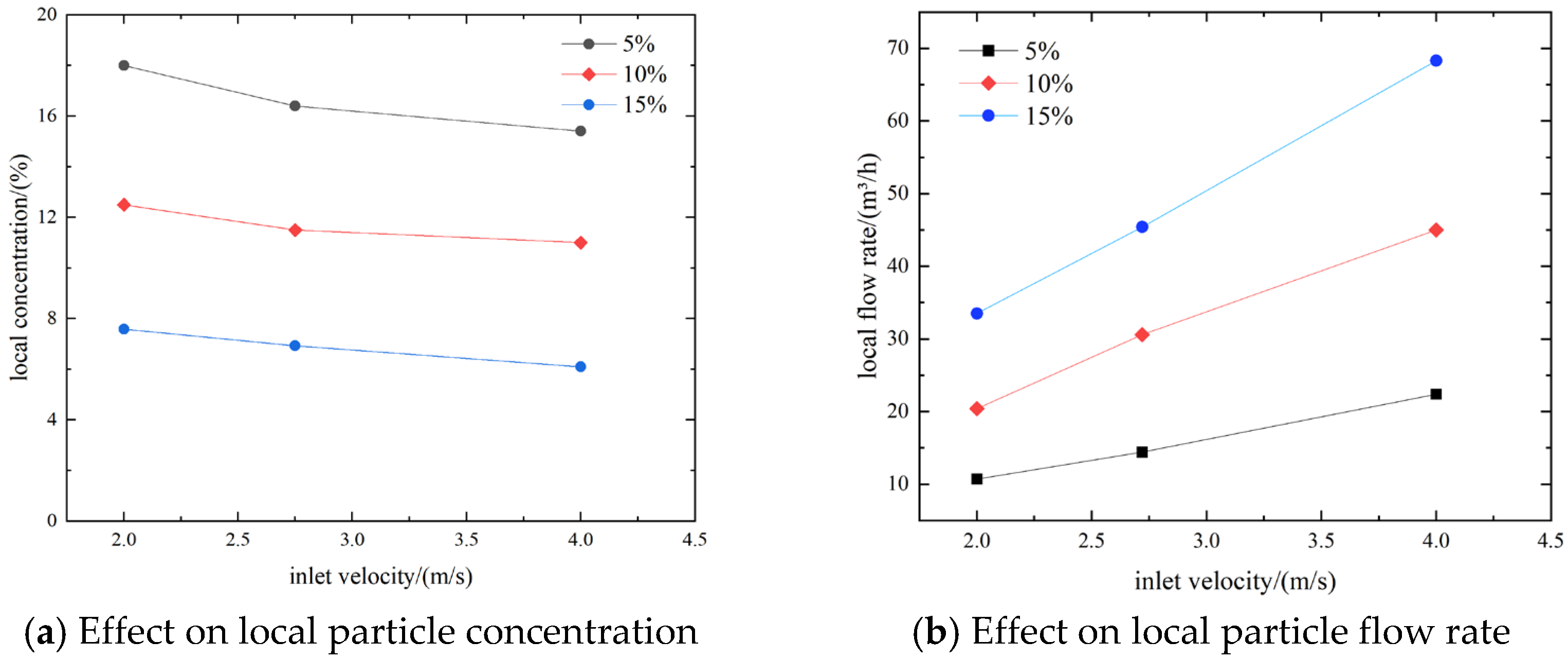
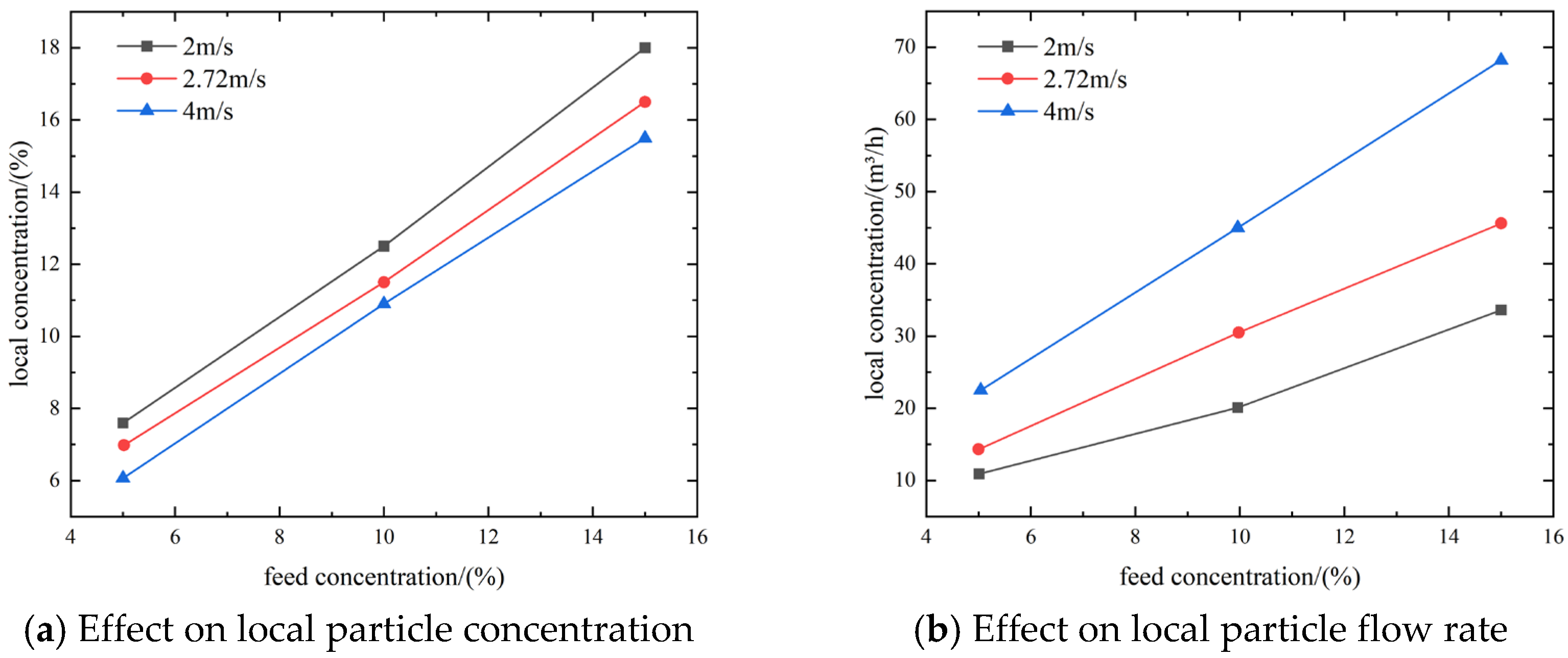
During the hydraulic lifting of crushed ore particles in deep-sea mining, the fundamental particle properties, such as particle size and density, can generally be regarded as known. Therefore, the selection of an appropriate inlet velocity and feed concentration is critical to the design of a deep-sea mining vertical lifting system. In this section, spherical particles are taken as a representative case to examine the influence of inlet velocity on particle transport behavior. In the simulations, the diameter of the spherical particles was set to 20 mm, and three inlet velocities, namely
= 2, 2.72, and 4 m/s, were considered. CFD-DEM coupling was employed to simulate the transport behavior of coarse spherical particles in the vertical lifting pipeline, with particular attention given to the local concentration and local flow rate of the spherical particles. The results are presented in
Figure 7a,b.
Figure 7a,b illustrates the effects of inlet velocity
on the local concentration and local flow rate of spherical particles in the vertical lifting pipeline, respectively. As shown in
Figure 7a, when the feed concentration
was 5%, the local concentration gradually decreased from 7.6% to 6.1% with increasing inlet velocity, corresponding to a total reduction of 1.5%. When the feed concentration
was 10%, the local concentration decreased from 12.53% to 10.94%, corresponding to a total reduction of 1.59%. When the feed concentration
was 15%, the local concentration decreased from 18.01% to 15.47%, corresponding to a total reduction of 2.54%. These results indicate that the local concentration decreases with increasing inlet velocity, and that the rate of decrease becomes more pronounced as the feed concentration increases. It can also be inferred from the figure that, if the inlet velocity were reduced below 2 m/s, the local concentration within the vertical lifting pipeline would increase further. However, considering the suspension requirement of particles in the vertical lifting pipeline, an excessively low inlet velocity would likely lead to pipeline blockage.
This trend can be physically explained by the enhanced fluid-carrying capacity at higher inlet velocities. As the inlet velocity increases, the drag force exerted by the fluid on the particles becomes stronger, which improves particle suspension and weakens the tendency of particles to accumulate locally within the pipe. Meanwhile, the higher axial liquid velocity shortens the residence time of particles in the observation section, so fewer particles remain locally at a given instant. In addition, stronger fluid motion promotes more rapid momentum exchange and mixing between the solid and liquid phases, which suppresses particle clustering and reduces local solids holdup. Therefore, although a higher inlet velocity increases the particle transport rate, it decreases the local particle concentration measured in the pipeline section.
As shown in
Figure 7b, when the feed concentration
was 5%, the local flow rate increased gradually from 10.78 m
3/h to 22.58 m
3/h with increasing inlet velocity, corresponding to an increase of 11.8 m
3/h. When the feed concentration
was 10%, the local flow rate increased from 20.36 m
3/h to 45.15 m
3/h, corresponding to an increase of 24.79 m
3/h. When the feed concentration
was 15%, the local flow rate increased from 33.64 m
3/h to 68.29 m
3/h, corresponding to an increase of 34.65 m
3/h. These results indicate that the local flow rate increases approximately linearly with increasing inlet velocity, and that the rate of increase becomes greater as the feed concentration rises. It can therefore be inferred that a higher inlet velocity and a higher feed concentration are beneficial for improving the transport efficiency of the vertical lifting pipeline. However, an excessively high inlet velocity will increase the pressure loss along the pipeline and impose more stringent performance requirements on the lifting pump.
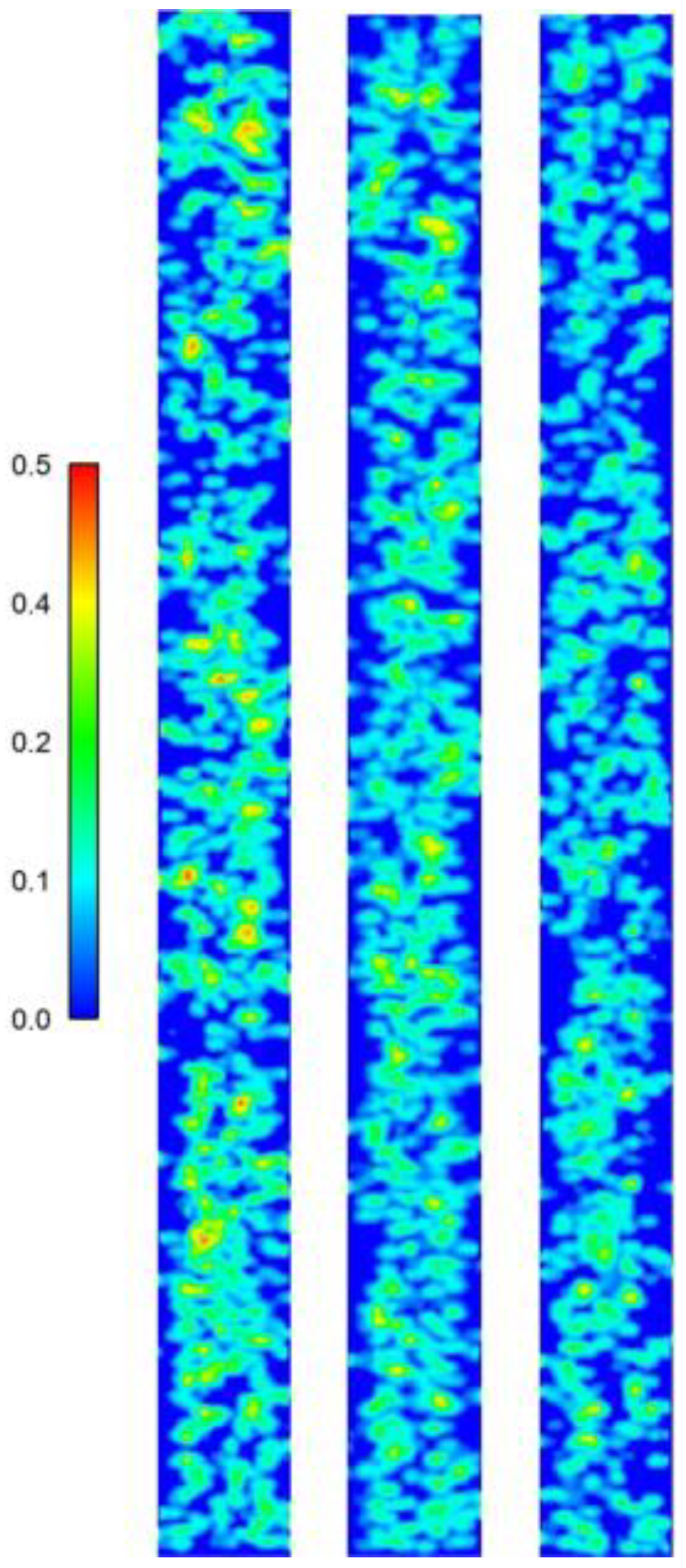
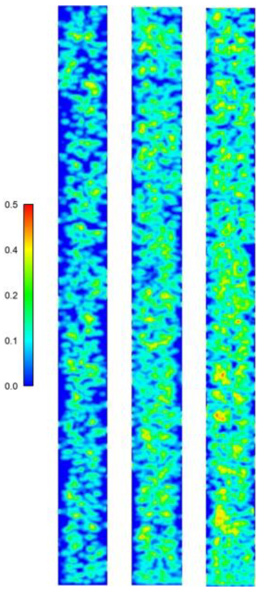
Figure 8 presents the volume fraction contours of spherical particles in the pipeline under the condition of a feed concentration
= 5% and inlet velocities
= 2, 2.72, and 4 m/s. At higher inlet velocities, the solid–liquid two-phase flow formed by spherical coarse particles and the fluid enters a uniformly mixed state more rapidly. Under lower inlet velocity conditions, by contrast, the transition of the spherical particles and the fluid into a uniformly mixed state becomes slower. Meanwhile, it can also be observed from
Figure 8 that, at lower inlet velocities, the particle concentration in the vertical lifting pipeline is higher. This finding is consistent with the results shown in
Figure 7a.
Physically, this behavior is mainly associated with the enhancement of fluid-carrying capacity and particle suspension at higher inlet velocities. When the inlet velocity is low, the upward drag exerted by the fluid is relatively weak compared with the combined effects of particle weight, interparticle collisions, and wall interactions. As a result, particles are more likely to remain locally accumulated, and the development of a uniformly mixed solid–liquid flow becomes slower. In contrast, as the inlet velocity increases, the stronger fluid drag and momentum exchange promote particle entrainment and upward transport, reduce particle residence time in the local pipe section, and weaken local high-volume fraction regions. Consequently, the particle phase becomes more uniformly distributed across the pipe, and the transition toward a stable mixed flow state is accelerated.
4.2. Effect of Feed Concentration on Lifting Performance
Building on the analysis in the preceding section, spherical particles were again taken as a representative case to investigate the effect of feed concentration on particle transport behavior. In the simulations, the diameter of the spherical particles was set to 20 mm, and the feed concentration
was specified as 5%, 10%, and 15%. CFD-DEM coupling was employed to simulate the transport behavior of spherical particles in the vertical lifting pipeline, with the local concentration and local flow rate of the spherical particles analyzed accordingly. The results are presented in
Figure 9a,b.
Figure 9a,b illustrates the effects of feed concentration
on the local concentration and local flow rate of spherical particles in the vertical lifting pipeline, respectively. As shown in
Figure 9a, when the inlet velocity
was 2 m/s, the local concentration increased from 7.6% to 18.01% with increasing feed concentration, corresponding to an increase of 10.41%. When the inlet velocity
was 2.72 m/s, the local concentration increased from 6.67% to 16.43%, corresponding to an increase of 9.76%. When the inlet velocity
was 4 m/s, the local concentration increased from 6.1% to 15.47%, corresponding to an increase of 9.37%. These results indicate that the local concentration increases with increasing feed concentration, while the rate of increase in local concentration decreases slightly as the inlet velocity rises. At the same time, the local particle concentration in the vertical lifting pipeline is greater than the feed concentration
, suggesting that particle retention is likely to occur within the pipeline.
As shown in
Figure 9b, when the inlet velocity
was 2 m/s, the local flow rate increased from 10.78 m
3/h to 33.64 m
3/h with increasing feed concentration, corresponding to an increase of 22.86 m
3/h. When the inlet velocity
was 2.72 m/s, the local flow rate increased from 14.51 m
3/h to 45.36 m
3/h, corresponding to an increase of 30.85 m
3/h. When the inlet velocity
was 4 m/s, the local flow rate increased from 22.58 m
3/h to 68.29 m
3/h, corresponding to an increase of 45.71 m
3/h. These results show that the local flow rate increases approximately linearly with increasing feed concentration, and that the rate of increase becomes higher as the inlet velocity rises.
Based on the results shown in
Figure 9, it may be inferred that selecting a higher feed concentration together with a higher inlet velocity can significantly improve the transport efficiency of the vertical lifting pipeline. However, a higher feed concentration also leads to an increase in the local concentration within the pipeline, thereby raising the risk of pipeline blockage. In addition, it increases the frequency of particle–particle and particle–wall collisions, which in turn causes a greater pressure loss along the vertical lifting pipeline during transport. Therefore, the selection of transport velocity and feed concentration should comprehensively account for multiple factors so as to determine an appropriate conveying velocity and slurry concentration.
Figure 10 presents the particle volume fraction contours of spherical particles in the pipeline for an inlet velocity of
= 2.72 m/s and feed concentrations
= 5%, 10%, and 15%. It can be seen from the figure that a higher feed concentration leads to a higher local concentration within the vertical lifting pipeline. Under conditions of relatively high feed concentration
, the solid–liquid two-phase flow formed by the spherical particles and the fluid reaches a uniformly mixed state more rapidly. However, the particle volume fraction contours in
Figure 10 under the condition of
= 15% also show that, although the spherical coarse particles and the fluid appear to be in a mixed state, a pronounced particle aggregation phenomenon still occurs within the vertical lifting pipeline. Such particle aggregation is unfavorable for hydraulic transport in the vertical lifting pipeline. Once the hydraulic conveying velocity changes, the aggregation phenomenon may be further intensified, thereby increasing the risk of blockage in the lifting pipeline. Therefore, in selecting the slurry transport concentration, a relatively low conveying concentration should be considered in order to mitigate particle aggregation and accumulation.
4.3. Effect of Particle Size on Lifting Performance
During the mixed hydraulic lifting of ore particles in deep-sea mining, particle size is also an important factor affecting the lifting performance of the vertical lifting system. Even when the inlet velocity and feed concentration are fixed, differences in particle size can still alter the transport behavior of particles within the lifting pipeline and the overall lifting efficiency of the system. In this section, spherical particles are taken as a representative case to analyze the effect of particle size on particle transport behavior. The inlet velocity was set to
= 2.72 m/s, the feed concentration
was specified as 5%, 10%, and 15%, and the diameter of the spherical particles was set to
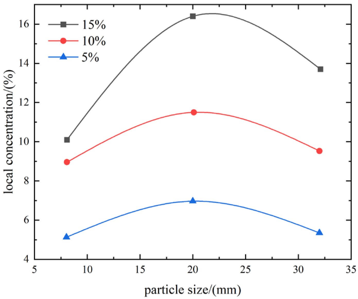
= 10, 20, and 30 mm. CFD-DEM coupling was employed to simulate the transport behavior of spherical particles in the vertical lifting pipeline, and the local concentration of spherical particles within the pipeline was analyzed. The results are shown in
Figure 11.
Figure 11 illustrates the influence of particle diameter on the local concentration in the vertical lifting pipeline and reveals the relationship between particle diameter
and local concentration. As the particle diameter
increased from 10 to 30 mm, the local concentration of particles in the vertical lifting pipeline exhibited a trend of first increasing and then decreasing. This indicates that, under different feed concentrations
, the variation pattern of local concentration remained essentially consistent as the particle diameter increased from 10 to 30 mm, with the local concentration reaching its maximum at approximately
= 20 mm. Furthermore, it can also be observed that when the particle diameter was
= 10 mm and the feed concentration
was relatively high (
= 10% and 15%), the local concentration in the vertical lifting pipeline was lower than the feed concentration
. This suggests that the local concentration in the vertical lifting pipeline is not necessarily greater than the feed concentration. A possible explanation for this phenomenon is that smaller particles exhibit better flow-following behavior under conditions of relatively high feed concentration and inlet velocity, such that particle retention becomes less pronounced, resulting in a local concentration lower than the feed concentration.
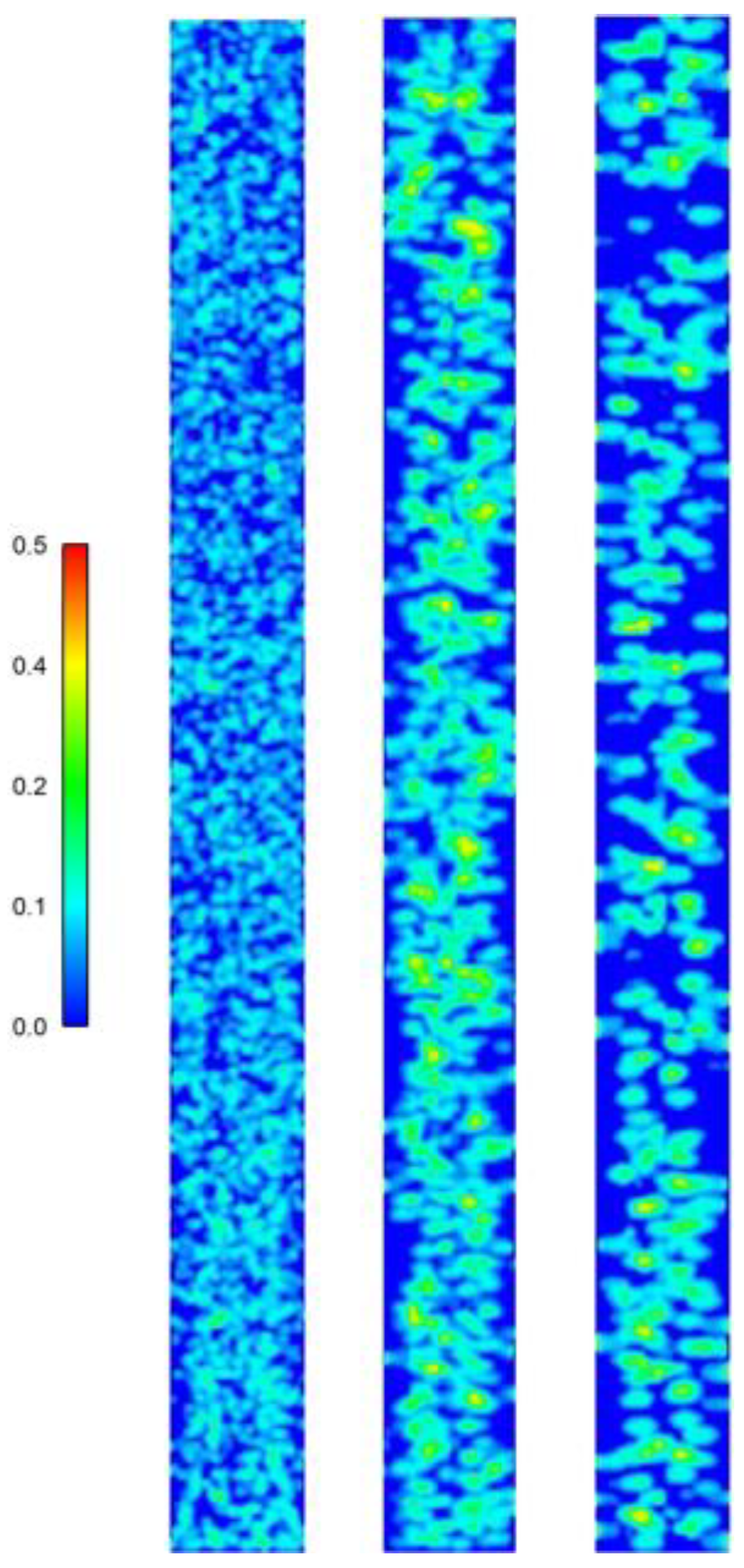
Figure 12 presents the particle volume fraction contours of spherical particles in the pipeline for an inlet velocity of
= 2.72 m/s, a feed concentration of
= 5%, and particle diameters
= 10, 20, and 30 mm. It can be clearly observed from the contours that when the particle diameter is relatively small (
= 10 mm), the solid–liquid two-phase flow formed by the spherical coarse particles and the fluid enters a uniformly mixed state more rapidly, and the mixed flow within the vertical lifting pipeline becomes more homogeneous. By contrast, when the particle diameter is larger, the transition of the mixed flow to a uniformly mixed state becomes slower, and particle aggregation is more likely to occur. This phenomenon is highly unfavorable for hydraulic transport in the vertical lifting pipeline. If particle aggregation is further intensified, blockage may develop, ultimately leading to pipeline obstruction.
4.4. Effect of Particle Shape on Lifting Performance
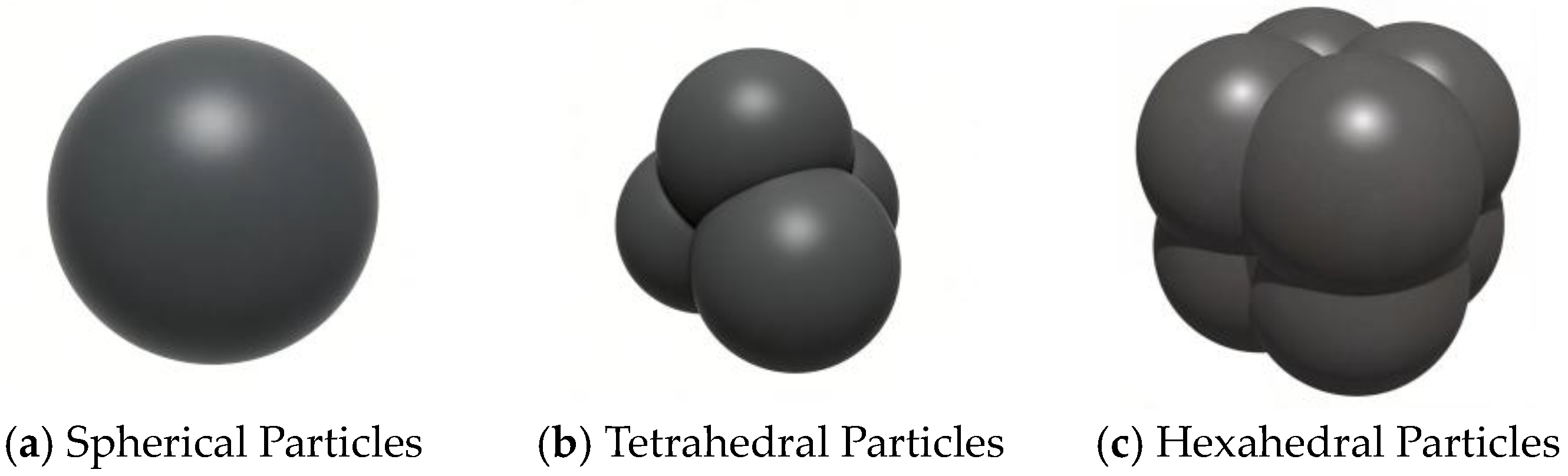
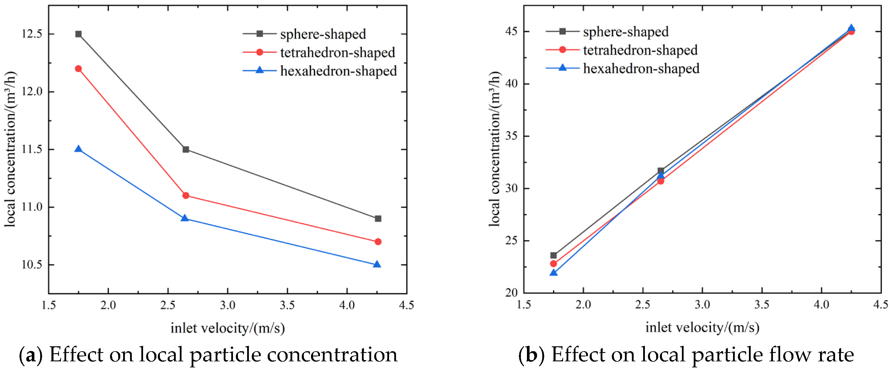
In practical deep-sea mining lifting systems, the lifted ore particles exhibit a variety of shapes, and particles with different geometries may display distinct transport behaviors in the vertical lifting pipeline. In this section, three particle shapes, namely spherical, tetrahedral, and hexahedral particles, were considered. Three inlet velocities,
= 2, 2.72, and 4 m/s, were selected, while the feed concentration was fixed at
= 10%. CFD-DEM coupling was employed to simulate the transport behavior of these three types of irregular particles in the vertical lifting pipeline, and the local concentration and local flow rate of the particles were analyzed. The results are shown in
Figure 13a,b.
Figure 13a,b illustrates the effects of inlet velocity
on the local concentration and local flow rate of irregular particles in the vertical lifting pipeline, respectively. As shown in
Figure 13a, when the particle shape was spherical, the local concentration gradually decreased from 12.53% to 10.94% with increasing inlet velocity, corresponding to a total reduction of 1.59%. When the particle shape was tetrahedral, the local concentration decreased from 12.15% to 10.75%, corresponding to a total reduction of 1.4%. When the particle shape was hexahedral, the local concentration decreased from 11.54% to 10.56%, corresponding to a total reduction of 0.98%. These results indicate that the local concentration decreases progressively with increasing inlet velocity. Under conditions of relatively low inlet velocity, the effect of particle shape on the local concentration in the vertical lifting pipeline is more pronounced.
As shown in
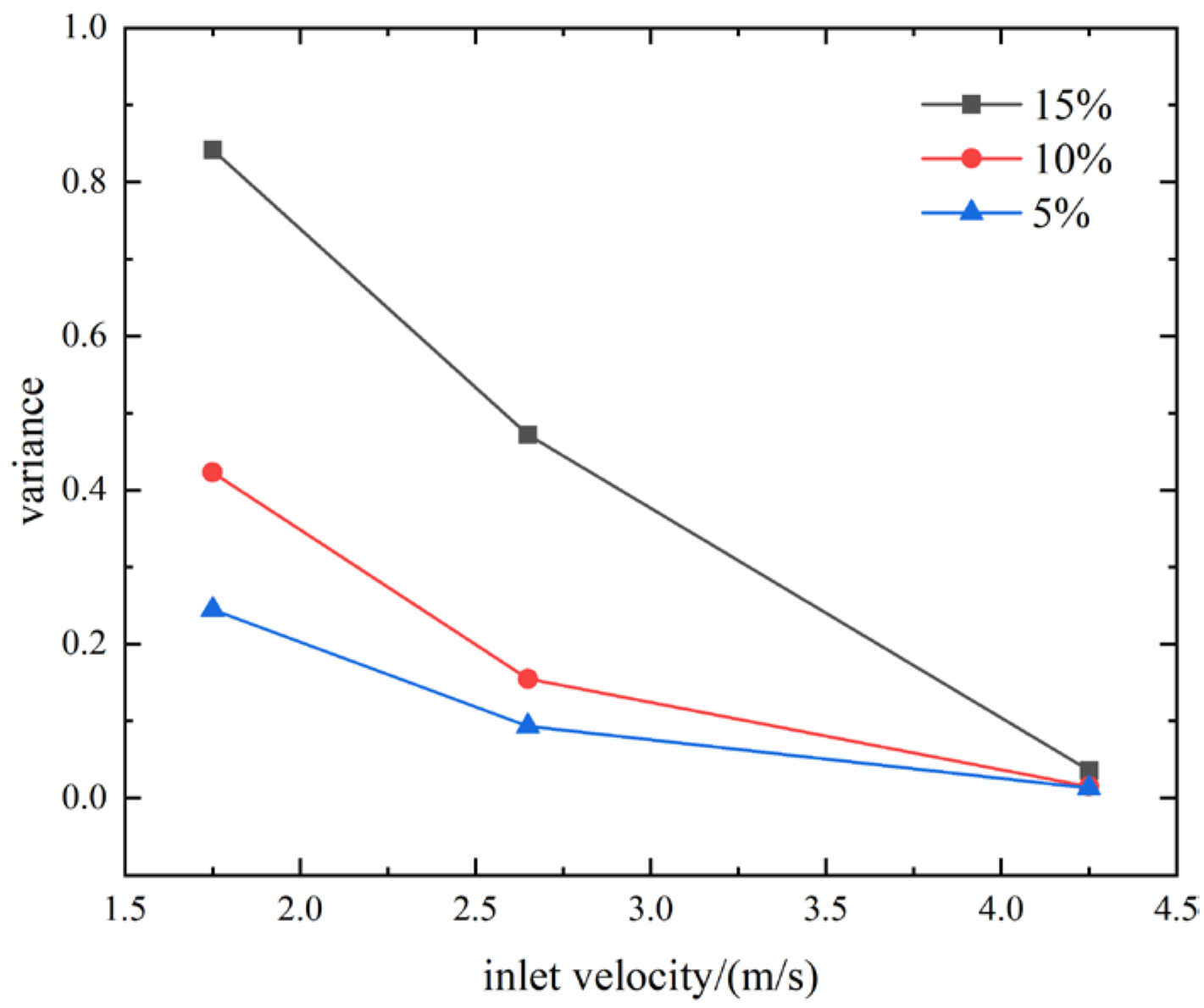
Figure 13b, the influence of particle shape on the local flow rate gradually decreases with increasing inlet velocity. In order to more clearly quantify the effect of particle shape on the local flow rate in the vertical lifting pipeline, the variance of the local flow rates of the three particle shapes was used in
Figure 14 to represent the shape effect. A larger variance indicates a stronger influence of particle shape on the local flow rate, whereas a smaller variance indicates a weaker influence. As can be seen from
Figure 14, when the inlet velocity was 2 m/s, the variance values corresponding to the three feed-concentration conditions were 0.25, 0.42, and 0.84, respectively, indicating that the effect of particle shape on the local flow rate becomes more pronounced as the feed concentration increases. However, with increasing inlet velocity, the influence of particle shape on the local flow rate gradually weakens, and when the inlet velocity reached 4 m/s, the effect of particle shape on the local flow rate under the three feed-concentration conditions approached zero. These results indicate that under conditions of relatively high feed concentration and low inlet velocity, particle shape exerts a pronounced influence on the local flow rate in the vertical lifting pipeline. By contrast, as the inlet velocity increases and the feed concentration decreases, the influence of particle shape on the local flow rate becomes progressively weaker.
4.5. Implications for Engineering Practice
- (1)
Inlet velocity plays a dominant role in the mixing uniformity, local concentration distribution, and transport efficiency of the vertical lifting process. A low inlet velocity delays two-phase mixing and increases the local concentration, thereby elevating the risks of particle accumulation and blockage. A high inlet velocity reduces the local concentration and increases the particle transport rate, but an excessively high velocity significantly increases the pressure drop and energy consumption along the pipeline.
- (2)
At a fixed inlet velocity, feed concentration determines the trade-off between particle throughput and transport stability. A low feed concentration corresponds to a relatively low particle flux and transport efficiency, whereas a high feed concentration facilitates the mixing process but is more likely to induce local accumulation and increase the risk of blockage.
- (3)
Particle size significantly affects flow uniformity and engineering feasibility. Smaller particles (e.g., 10 mm) help reduce local concentration peaks and improve flow uniformity, thereby lowering the probability of blockage, but they also impose higher requirements on crushing and separation processes. Larger particles slow the mixing process and place greater demands on pump lifting capacity.
- (4)
The influence of particle shape on local concentration and local flow rate is mainly manifested under conditions of low inlet velocity and high feed concentration. As the inlet velocity increases, the shape effect gradually weakens. Within the investigated inlet velocity range (2–4 m·s−1), the local concentration of spherical particles is higher than that of tetrahedral and hexahedral particles.
4.6. Limitations and Future Work
Nevertheless, the present study still has several limitations. First, the numerical model focuses on the initial mixing and early stabilization stages of solid–liquid two-phase flow in a local vertical straight-pipe section, rather than the full kilometer-scale transport process in an actual deep-sea lifting system. Second, the particles were simplified into several representative sizes and shapes, while more complex characteristics, such as wide particle size distributions, particle breakage, and stronger irregularity, were not considered. Third, the simulations were conducted under idealized operating conditions and did not include full system-level coupling with lifting pumps, transient flow fluctuations, or variations in deep-sea environmental conditions. In addition, direct experimental data corresponding to the present pipe configuration and operating condition matrix are not yet available, and thus a dedicated experimental validation has not been conducted in this study. Therefore, the current model should be regarded as a physically enhanced numerical framework for comparative parametric analysis, rather than a fully validated predictive tool for all engineering scenarios. In future work, larger-scale simulations, more realistic particle descriptions, and experimental validation under representative vertical lifting transport conditions will be carried out to further assess and improve the reliability and engineering relevance of the present model.