1. Introduction
The pursuit of accurate and efficient marine environmental monitoring remains significantly constrained by the limitations of conventional observational methods, which typically suffer from low spatiotemporal resolution, significant transmission latency, and fragmented spatial coverage [
1,
2]. These challenges impede the realization of real-time, three-dimensional, and high-resolution collaborative perception across maritime and aerial domains [
3]. To address this, the development of cross-medium acoustic–radio collaborative networks, which seamlessly integrate underwater acoustic and surface radio communications, has emerged as a pivotal technological pathway for unified and real-time data transmission throughout the marine three-dimensional space [
4,
5]. Such networks architect a cohesive data return framework by interconnecting underwater sensor nodes, sea surface buoy nodes, and aerial unmanned nodes with dual acoustic–radio capabilities. These nodes form a three-dimensional communication network spanning air, sea surface, and underwater environments to improve the speed and reliability of marine data acquisition.
Within this integrated “underwater-surface-air” architecture, the routing protocol functions as the “central nervous system.” Its design critically determines core performance metrics for cross-medium data transfer—including throughput, packet delivery ratio (PDR), and end-to-end delay—forming the foundational element for the system’s reliable and efficient operation.
Currently, marine networks predominantly consist of sea surface radio networks and underwater acoustic networks. Research on routing methods is accordingly divided into two main categories: sea surface radio routing and underwater acoustic routing. Sea surface network routing typically employs traditional radio network routing protocols and their improved variants, primarily including table-driven routing (e.g., DSDV, OLSR) [
6,
7], on-demand routing (e.g., AODV, DSR) [
8,
9], geographic routing (e.g., GPSR) [
10], hybrid routing, and intelligent routing [
11,
12]. Underwater acoustic network routing mainly encompasses geographic routing (e.g., VBF, DBR) [
13,
14], virtual zone-based routing (e.g., HH-VBF, HARB) [
15], opportunistic routing (e.g., SBR) [
16], and intelligent routing [
17], among others. Reactive routing protocols such as AODV are widely adopted in surface ad hoc networks due to their low maintenance overhead. However, when directly applied to cross-media networks incorporating highly latent and disruption-prone underwater acoustic links, their control packet flooding mechanisms can induce severe underwater collisions. Existing underwater acoustic routing protocols primarily focus on addressing localization challenges and adapting to dynamic link conditions. For instance, depth-based routing approaches (e.g., DBR) offer efficient solutions for uploading data to surface gateways, while the concept of opportunistic routing provides a framework for selecting reliable relays in time-varying channels. Nevertheless, the application of acoustic routing protocols in cross-media transmission networks faces significant limitations, including performance mismatches with radio links and difficulties in ensuring real-time routing performance. In summary, most existing routing methods are designed for single-medium networks and are ill-suited for heterogeneous networks integrating both acoustic and radio transmission media.
In acoustic–radio collaborative networks, underwater acoustic and radio transmission methods exhibit significant disparities in data rate, latency, and link stability. To address these differences, existing approaches generally fall into two categories: separate networking above and below the sea surface or integrated cross-media networking.
Several efforts have been made to design routing mechanisms tailored to such heterogeneous environments. For instance, ref. [
18] proposed a hop-count-based underwater acoustic routing protocol using multiple buoy nodes to minimize the hop distance from underwater nodes to the surface, complemented by radio opportunistic routing in the surface layer—though it only supports unidirectional transmission. Similarly, ref. [
19] introduced an opportunistic routing algorithm incorporating depth weighting and residual energy for underwater segments and location-based priority sorting for surface forwarding, yet it remains constrained to unidirectional data flow. Other works, such as [
20], adopted a cross-media adaptive strategy combining AODV for surface routing and HH-VBF for underwater routing, with pre-transmission link delay estimation to decide between media. However, this method requires prior knowledge of the destination location. More recently, ref. [
21] presented a hybrid routing protocol (RAOH) that partitions the network into surface and acoustic subnetworks, applying on-demand routing and opportunistic forwarding to reduce signaling overhead and delay.
Despite these advances, most current protocols still rely on segmented networking strategies and are predominantly designed for upward (underwater-to-surface) communication, thereby limiting their applicability in bidirectional or dynamic marine scenarios. Moreover, the direct application of conventional ad hoc routing protocols like AODV or OLSR in cross-media settings often leads to excessive control overhead, frequent underwater collisions, and degraded end-to-end performance due to the inherent mismatch between radio and acoustic link characteristics [
22].
To overcome these limitations, this paper proposes an enhanced routing framework for acoustic–radio collaborative networks. In contrast to prior works, our approach does not assume unidirectional traffic or a priori destination information, nor does it depend on fully separated subnetworks. Instead, we introduce a unified routing mechanism that coordinates medium-aware path selection with cross-layer link stabilization. Specifically, our contributions include the following:
- (1)
A modality-aware route initiation scheme, in which surface relay nodes intelligently steer route requests according to the destination’s modality—acoustic or radio—thereby curtailing superfluous broadcasting in the acoustic domain;
- (2)
A composite link stability metric that jointly optimizes hop count and channel quality, facilitating reliable path selection beyond minimal-hop routing;
- (3)
An on-demand HELLO messaging strategy coupled with a dual-reply confirmation mechanism from underwater destinations, which collectively reduce control flooding in acoustic links and expedite route establishment.
These innovations collectively address key shortcomings of existing protocols—such as control overhead, delay–hop mismatch, and link instability—while enabling efficient bidirectional communication in integrated acoustic–radio marine networks.
In contrast to existing cross-medium protocols such as [
20,
21], which typically employ a segmented approach (radio AODV for surface and geographic routing for underwater), CACN-OAODV introduces a unified medium-aware initiation mechanism. This enables buoy nodes to intelligently filter RREQs based on the target node type, fundamentally reducing the broadcast storm at the water–air interface.
The remainder of this paper is organized as follows.
Section 2 elaborates on the acoustic–radio collaborative network framework, including the composition of aerial, surface buoy, and underwater nodes. To ensure the realism of the simulation environment, we introduce and detail four transmission loss models (air-to-air, air-to-sea surface, sea surface-to-sea surface, and underwater acoustic) as well as tailored MAC layer protocols for radio and acoustic channels. This section also evaluates the performance of conventional routing protocols (AODV, DSDV, OLSR) across three scenarios (underwater-to-underwater, underwater-to-air, air-to-underwater), focusing on key metrics such as PDR, throughput, and end-to-end delay, and identifies critical issues of AODV (excessive control overhead, low PDR, high latency, and unstable links).
Section 3 presents the performance validation of the proposed CACN-OAODV protocol. We first determine the optimal parameter
for the link stability factor, then compare CACN-OAODV with conventional protocols in the three scenarios, quantifying improvements in PDR, throughput, and delay.
Section 4 analyzes the core reasons for performance gains, discusses the impact of node mobility on routing stability, and outlines limitations and future research directions. Finally,
Section 5 summarizes the key innovations of the CACN-OAODV protocol and its effectiveness in enhancing the performance of marine cross-medium acoustic–radio collaborative networks.
2. Materials and Methods
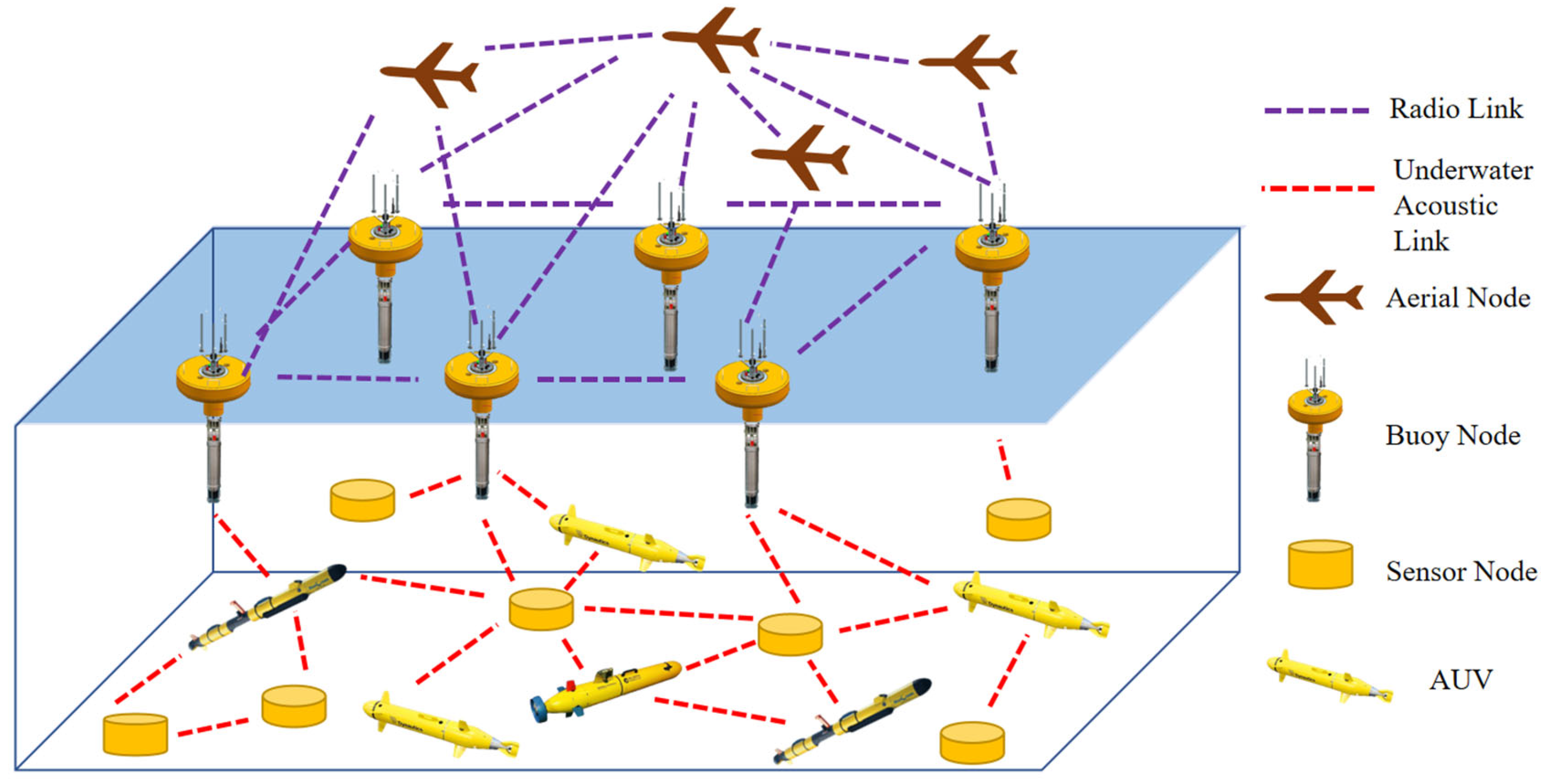
An above-water and underwater acoustic–radio collaborative network can be regarded as a heterogeneous Mobile Ad Hoc Network (MANET). It consists of aerial nodes, surface buoy nodes, and underwater nodes. Nodes above and on the sea surface use radio for communication, while underwater nodes use acoustics. Surface buoy nodes are equipped with both radio and acoustic communication capabilities, enabling cross-medium data transfer. All nodes are mobile with speeds depending on their type. The overall topology of the proposed acoustic–radio collaborative network is illustrated in
Figure 1. When establishing an acoustic–radio collaborative network, it is necessary to consider the transmission loss models for underwater acoustics and radio, as well as the MAC layer protocols.
In this paper, the following radio and underwater acoustic transmission loss models are used.
- (A)
Radio transmission loss models
Three wireless transmission loss models are employed: air-to-air, air-to-sea surface, and sea surface-to-sea surface. The air-to-air model represents the transmission link loss between control aircraft. This is point-to-point transmission, so the traditional Friis propagation loss model [
23] can be used. The other two models are developed separately based on the height difference between the sending and receiving nodes. If this difference is large, the air-to-sea transmission loss model should be used [
24]. This model incorporates the pitch angle, altitude difference, and the presence of obstacles between nodes.
The probability of line-of-sight communication depends on environmental conditions, the positions of the aerial nodes and water surface buoys, and the height of aerial nodes, which is given by
where
h is the height difference between the nodes, r is the horizontal distance between the water surface buoy node and air node, and
is the elevation angle between these nodes. The parameters
z1 and
z2 depend on the environment, and the values used here are
z1 = 4.88 and
z2 = 0.43. The path loss for line-of-sight and non-line-of-sight communication is
respectively, where
is the carrier frequency, c is the speed of light,
is the distance between the nodes, and
and
are the additional transmission losses for line-of-sight and non-line-of-sight communication, which are 0.1 and 21, respectively, based on the results in [
25]. Combining the above expressions gives the air–sea transmission path loss, which is given by
The sea surface-to-sea surface transmission loss model is the improved SPM model that incorporates dual path reflection and water vapor absorption [
26], with the formulation as follows:
Ls is the SPM transmission loss, is the dual path reflection transmission loss, is the cloud and fog attenuation loss, and is the water vapor absorption attenuation loss. The dual path reflection model can be significant for radio waves close to the sea.
- (B)
Underwater acoustic transmission loss models
The acoustic–radio collaborative network uses acoustic communication underwater. The underwater acoustic transmission link model in the NS-3 simulation platform [
27] is employed. The attenuation of sound waves is
is the signal frequency;
is the distance between nodes;
) is the underwater acoustic propagation loss, which is related to the distance between nodes; dm is the distance traveled by the sound waves;
is the sound absorption coefficient; and k is the attenuation factor. If the transducer sound is viewed as a spherical extension, then k = 1, and if it is a cylindrical extension, k = 2. According to Thorp’s empirical formula, the sound absorption loss when
is
when
is
The underwater noise model is
is ocean turbulence noise,
is wind and wave noise, and
is shipping noise, all of which are given by
is the thermal noise; s is the shipping factor, which, for light to heavy shipping, is in the range [0, 1]; and w is the wind speed.
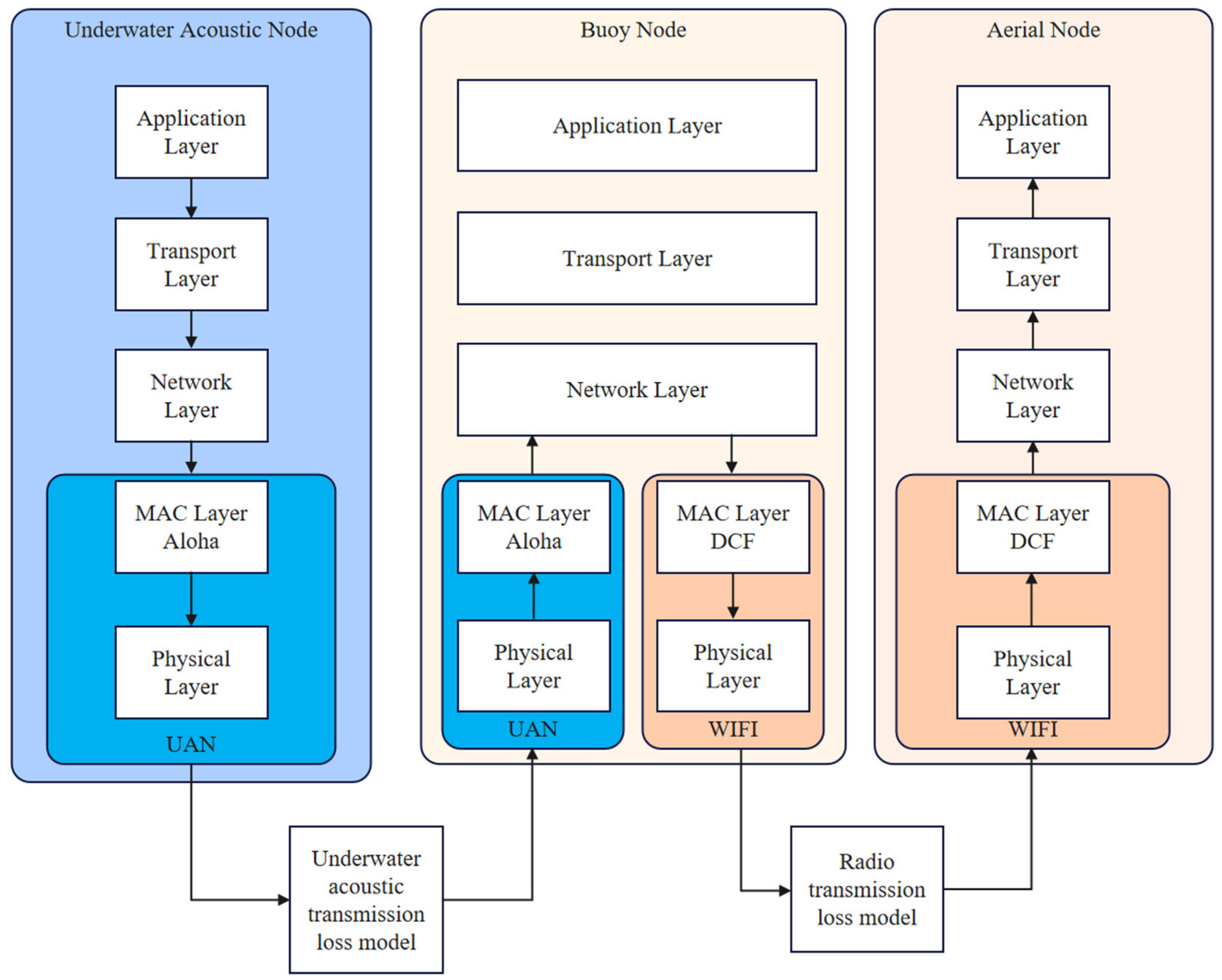
In the acoustic–radio collaborative network, two MAC protocols are employed, tailored to the characteristics of the two-transmission medium. The underwater acoustic MAC layer uses the “send as long as there is data” Aloha protocol. For the radio MAC layer, the 802.11 protocol in Distributed Coordination Function (DCF) mode is employed. At the application layer, network sockets are used to transmit and receive data packets. The User Datagram Protocol (UDP) is employed in the transport layer to provide a connectionless service to minimize the transmission of control signaling and reduce energy consumption.
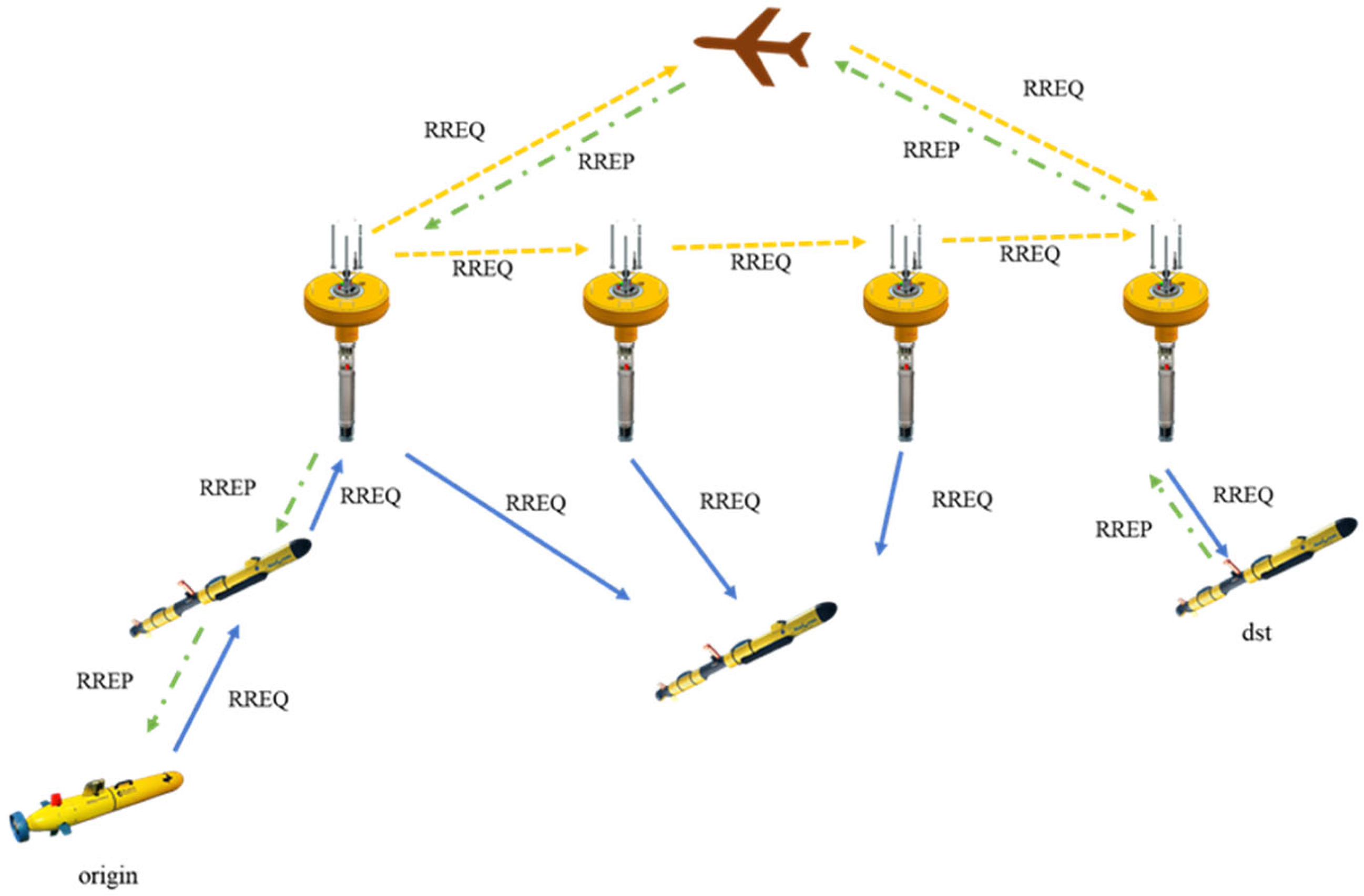
Since the network layer is decoupled from the other layers, the data in both types of links are combined into network layer packets to integrate underwater acoustic and radio data. Each acoustic–radio buoy node is assigned two IP addresses, one for underwater acoustic communication and the other for radio communication. The acoustic–radio collaborative network framework is illustrated in
Figure 2.
To evaluate general communication patterns, we define a bidirectional traffic matrix. It comprises 11 communication pairs, including 5 uplink flows (underwater-to-air), 5 downlink flows (air-to-underwater), and 1 local underwater pair. All nodes utilize UDP for data transmission, with a constant bit rate (CBR) of 10 kbps for acoustic links and 2 Mbps for radio links and a fixed packet size of 320 bits.
Conventional routing protocols can be categorized into three types based on table maintenance: on-demand, table-driven, and geographic location-based. Since the acoustic–radio collaborative network considered here has mobile nodes, exchanging location information between nodes in real time can result in significant overhead. Therefore, geographic location-based protocols are not suitable.
In AODV routing, if a source node with data to send does not have a route to the destination node, a routing request is broadcast to discover a path. Upon receiving this request, a node first establishes a route to the source node and then checks its routing table for a route to the destination node. If such a route exists, it returns a routing reply; otherwise, it increases the hop count and broadcasts the routing request. A surface buoy node receiving a routing request employs both its underwater acoustic and radio communication devices to forward the routing request. When a node with a valid route to the destination node or the destination node is reached, it unicasts a routing reply along the path to the source node. Upon receiving this reply, the source node establishes a route to the destination node and begins data transmission. AODV routing in the acoustic–radio collaborative network is illustrated in
Figure 3.
All nodes in the network periodically broadcast Hello messages. When a node receives a Hello message, it establishes a neighbor relationship. If a node does not receive a Hello message from a given neighbor for an extended period, it checks its routing table to see if there is a route that passes through this node. If such a route exists, a Routing Error (RERR) message is sent along this route back to the source node to notify that the route has become invalid.
With the DSDV protocol in the acoustic–radio collaborative network, each node maintains a routing table, and these tables are periodically broadcast. Buoy nodes use both underwater acoustic and radio communication devices to send their routing tables. When a new node joins the network, it broadcasts its information. When other nodes receive this information, they update their routing tables and broadcast the updated tables. This ensures that all nodes have current path information for all nodes in the network.
In the acoustic–radio collaborative network, the OLSR protocol requires all nodes to periodically send HELLO messages. Buoy nodes use both underwater acoustic and radio communication devices to transmit these messages. All nodes randomly select several Multi-Point Relay (MPR) nodes to ensure that each node is connected to at least one MPR node. MPR nodes broadcast Topology Control (TC) messages across the network, which contain information about their child nodes. Only MPR nodes can forward TC messages. Each node establishes and updates the network topology and obtains a global routing table. When a node needs to communicate, it consults the routing table to obtain the necessary routing information.
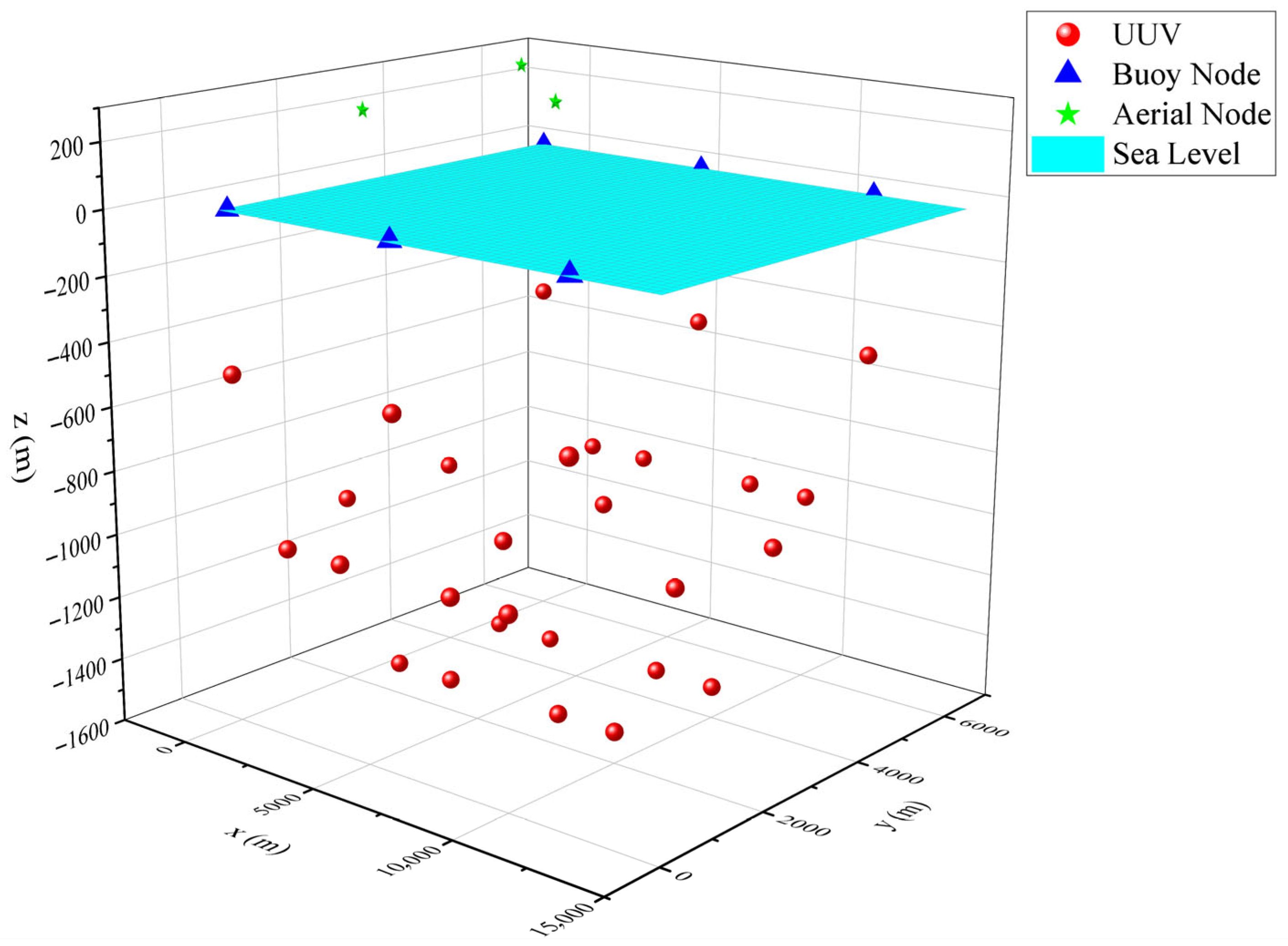
The performance of the three routing protocols is evaluated on the marine cross-medium acoustic–radio collaborative network. The underwater acoustic transmission range is generally shorter than that of radio, so there are more underwater acoustic nodes than radio nodes. The underwater nodes are deployed at different depths, with shallow nodes serving as relay nodes. The topology used for the simulations is shown in
Figure 4. The network consists of 28 underwater nodes, 6 sea surface buoy nodes, and 3 aerial nodes. The simulation parameters are given in
Table 1.
In this paper, simulation is used to evaluate the performance of the acoustic–radio collaborative network using the AODV, DSDV, and OLSR protocols. The PDR, throughput, and end-to-end delay were obtained for three transmission scenarios: both the send and receive nodes at a depth of 1000 m underwater, the send node 1000 m underwater and the receive node in the air, and the send node in the air and the receive node 1000 m underwater. The routing overhead was also obtained for the scenario where both send and receive nodes are at a depth of 1000 m underwater.
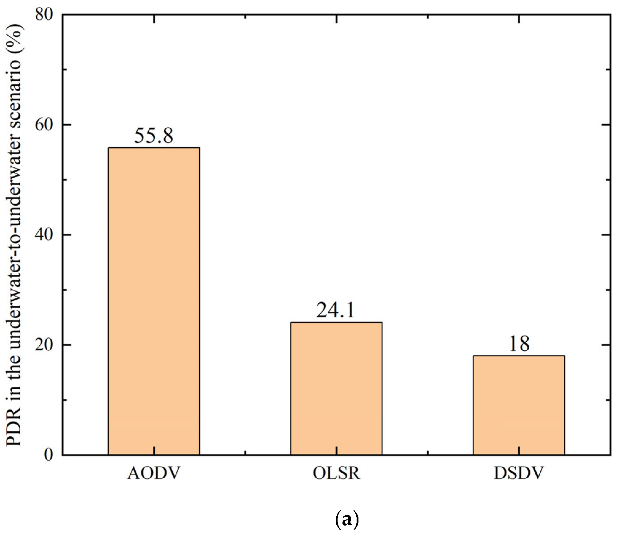
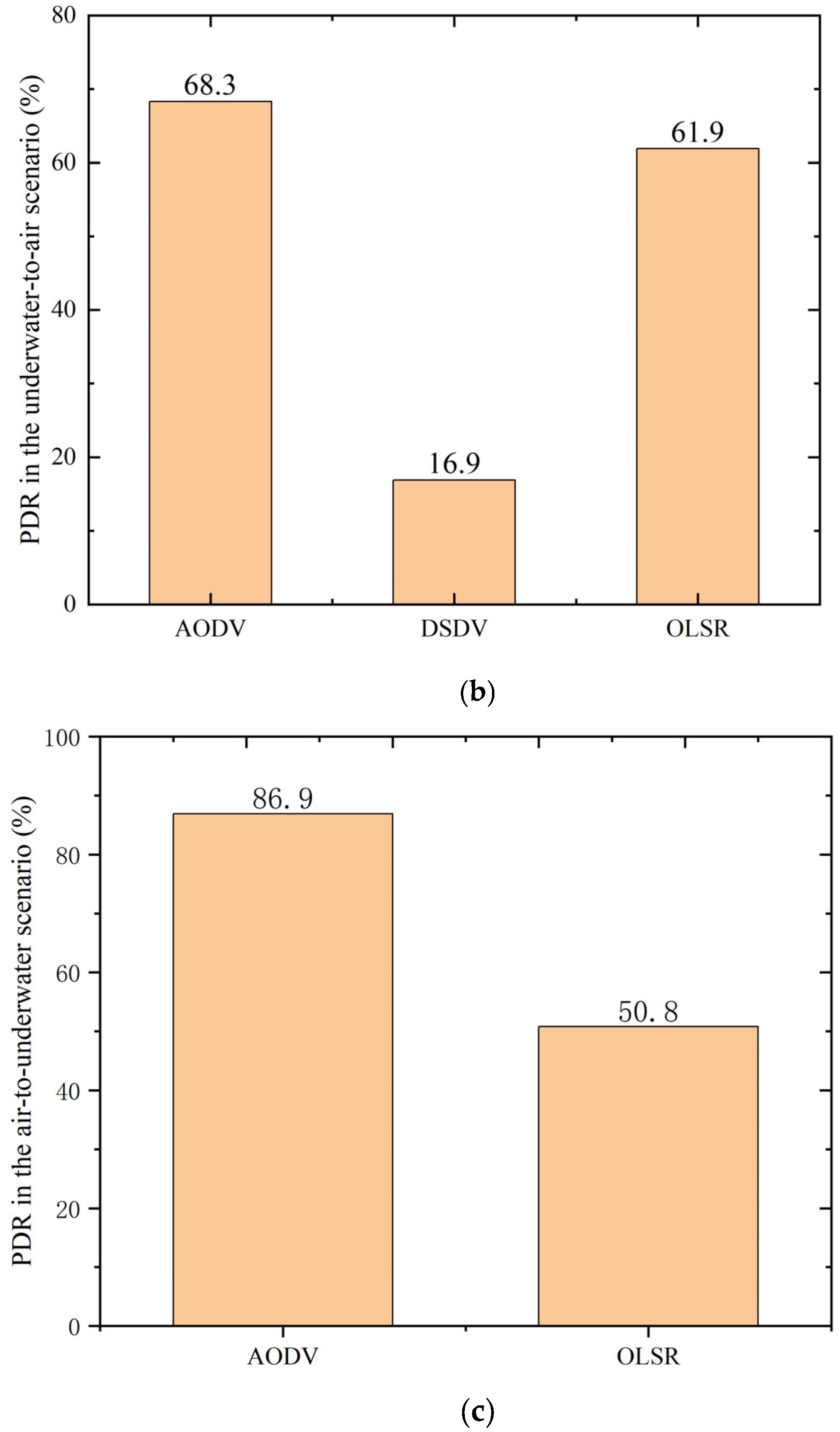
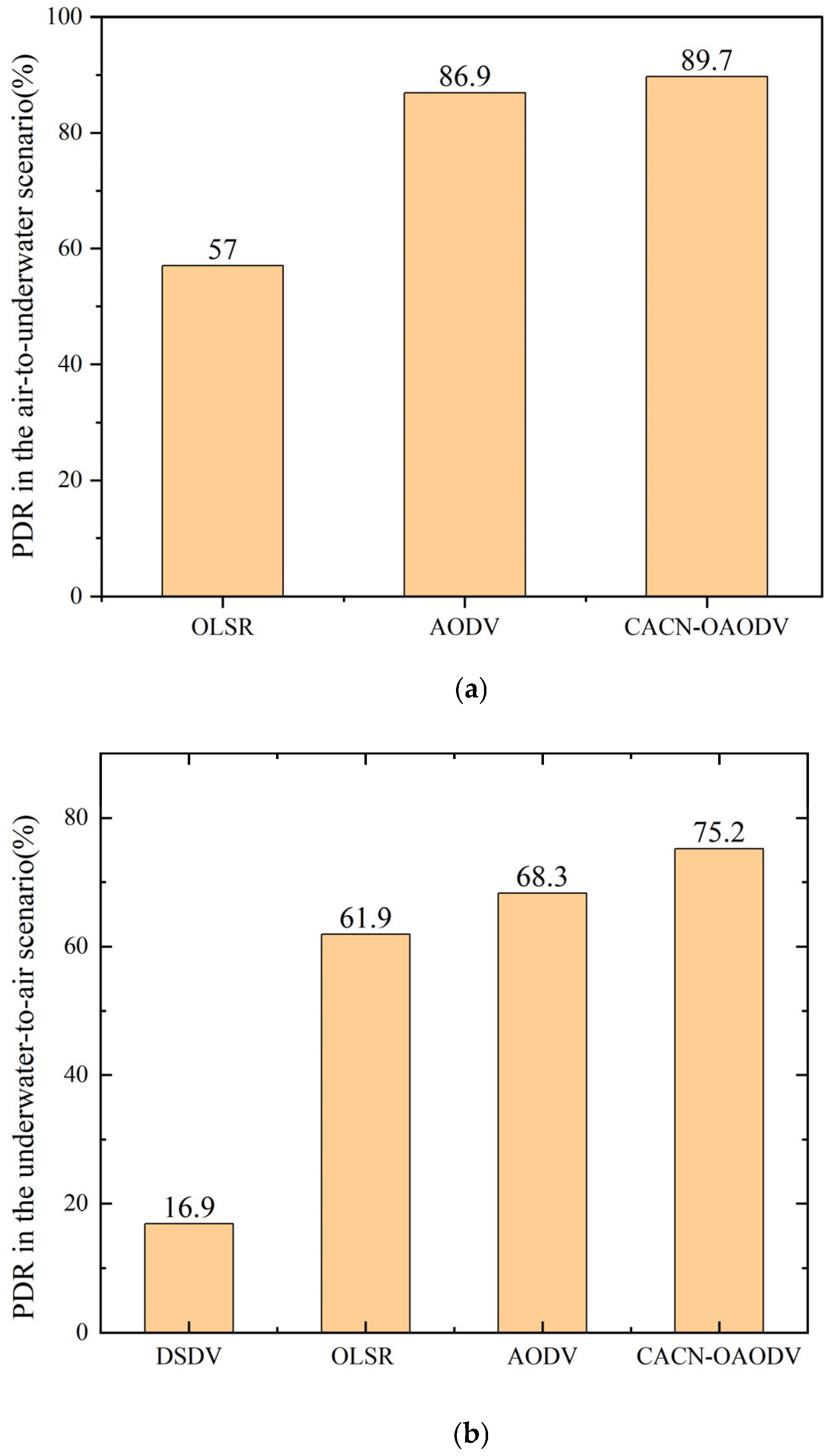
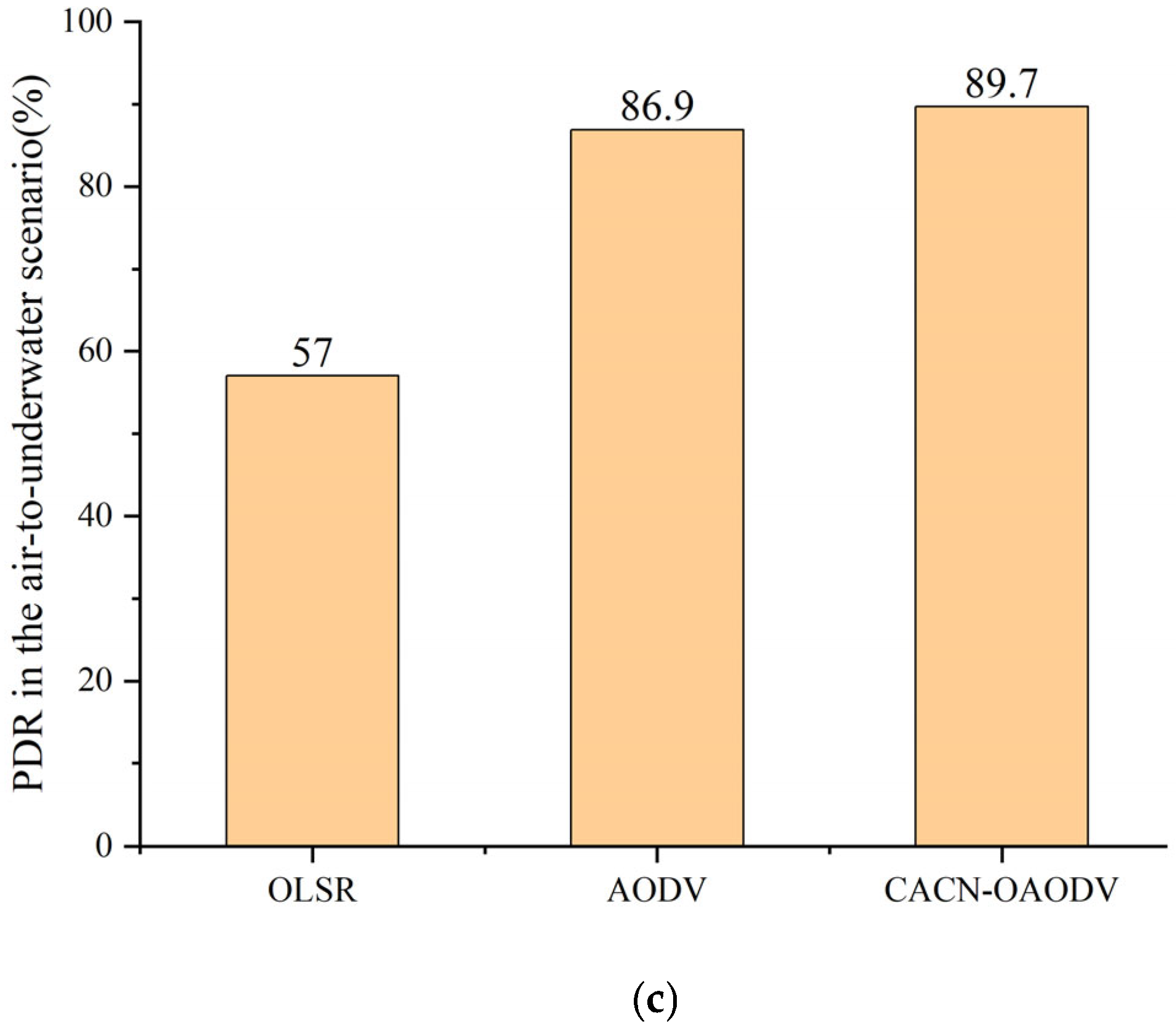
The PDR for the three scenarios is given in
Figure 5. It can be observed that among conventional routing protocols, AODV achieves relatively higher PDR than DSDV and OLSR. However, its performance is still limited by excessive control overhead and frequent route disruptions in heterogeneous acoustic–radio environments. In the underwater-to-underwater scenario, AODV outperforms OLSR by approximately 31%, and in the underwater-to-air and air-to-underwater scenarios, the difference is about 6% and 36%, respectively. AODV is superior because OLSR and DSDV are table-driven routing protocols that require continuous maintenance of global routing tables. This results in significant routing overhead and increases the likelihood of packet collisions in underwater acoustic channels. In contrast, AODV is an on-demand routing protocol, so the overhead for routing establishment and maintenance is lower, which reduces the probability of packet collisions. Specifically for the air-to-underwater scenario, DSDV simulation was conducted, but no valid data (e.g., PDR, throughput) were obtained. This stems from DSDV’s table-driven mechanism: continuous global routing table maintenance causes excessive overhead, amplified in the radio–acoustic air-to-underwater environment, leading to total packet collision or loss.
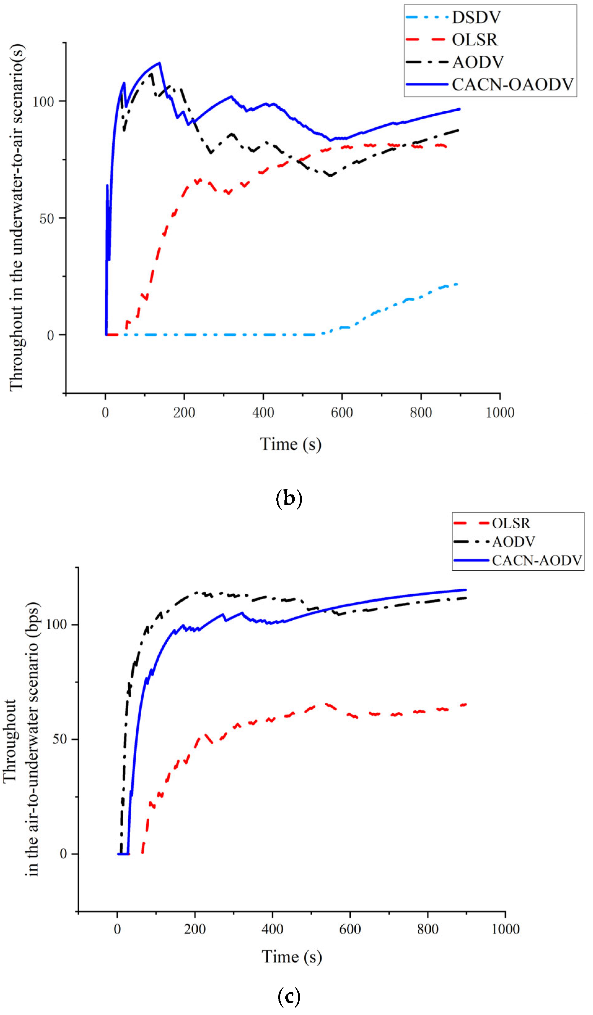
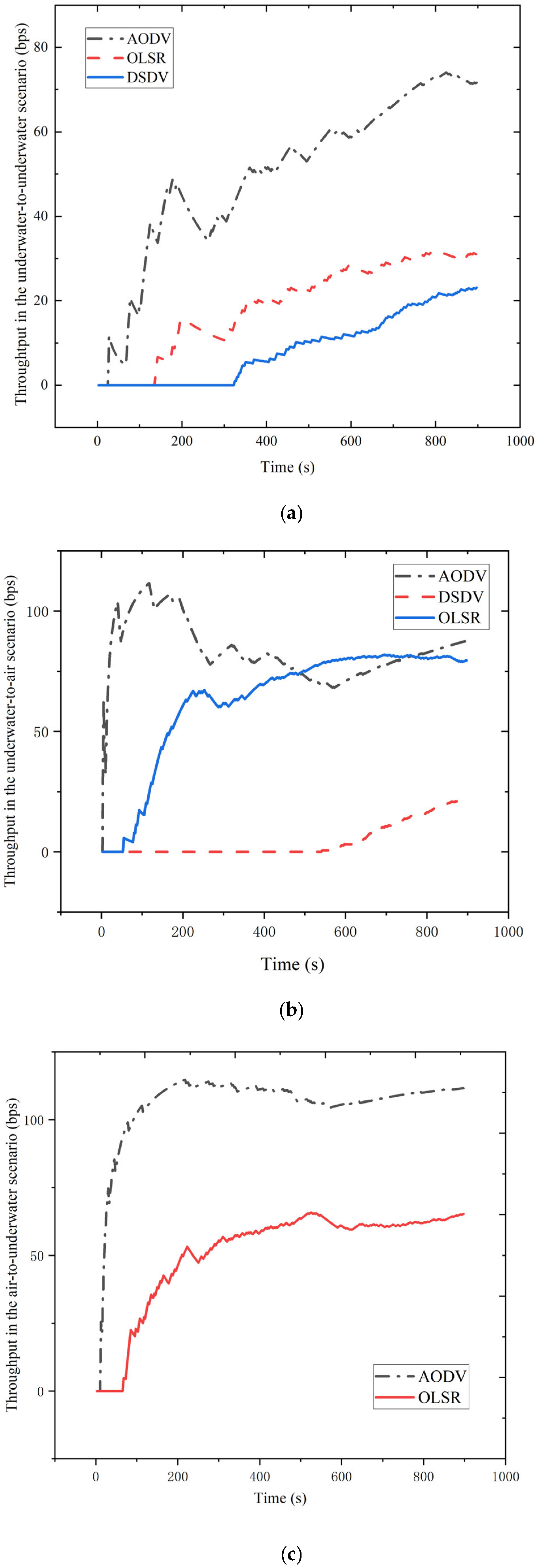
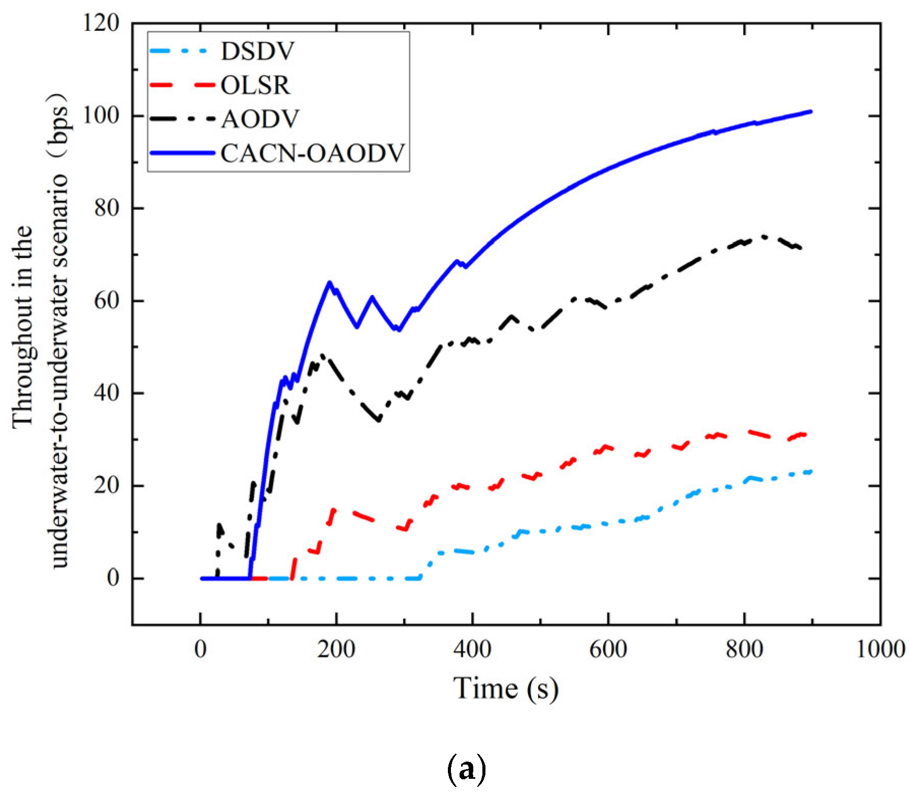
The throughput for the three scenarios is given in
Figure 6. This shows that in all cases, AODV provides higher throughput among conventional routing protocols; however, its performance degrades under dynamic cross-medium conditions. It outperforms OLSR by approximately 40 bps in the underwater-to-underwater scenario and by about 8 bps and 46 bps in the underwater-to-air and air-to-underwater scenarios, respectively. DSDV has a throughput of 0 in the air-to-underwater case. Note that after 200 s, the throughput of AODV in the underwater-to-air scenario begins to decline. This is due to the high mobility of aerial nodes, which causes frequent changes in the network topology. This necessitates routing re-establishment, which leads to a decrease in throughput. In contrast, OLSR continuously updates routes, resulting in a more stable throughput compared to AODV.
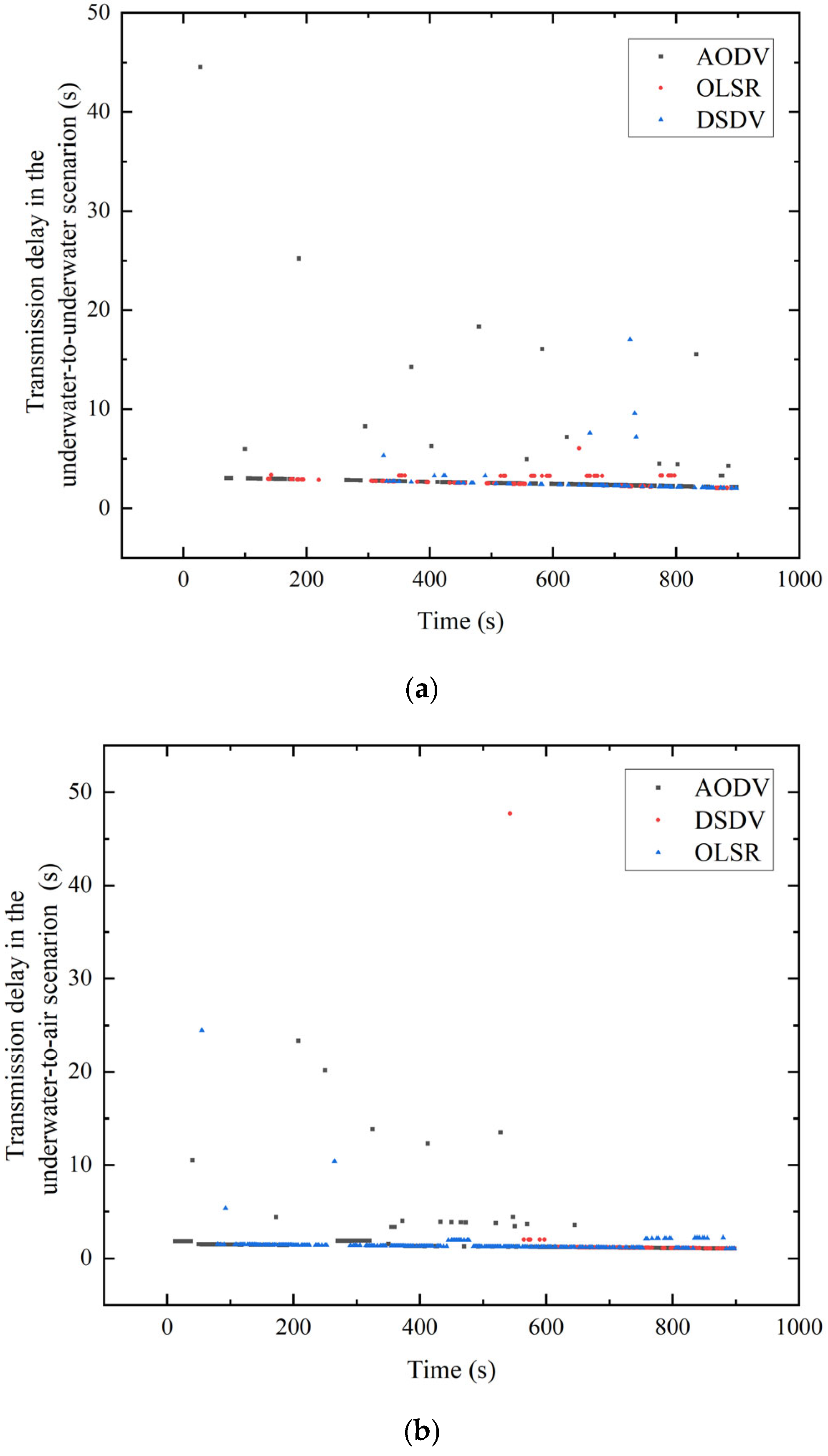
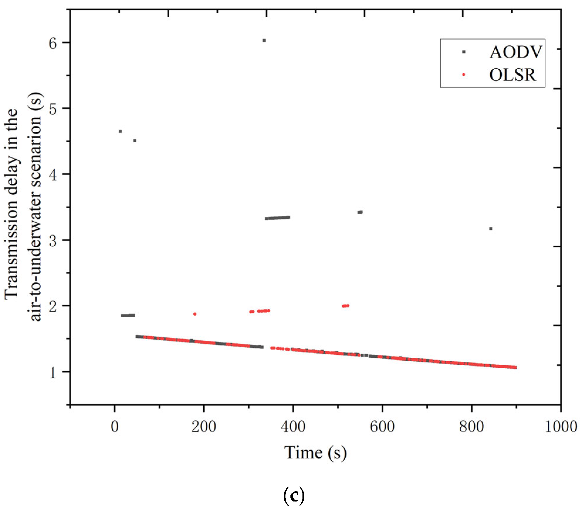
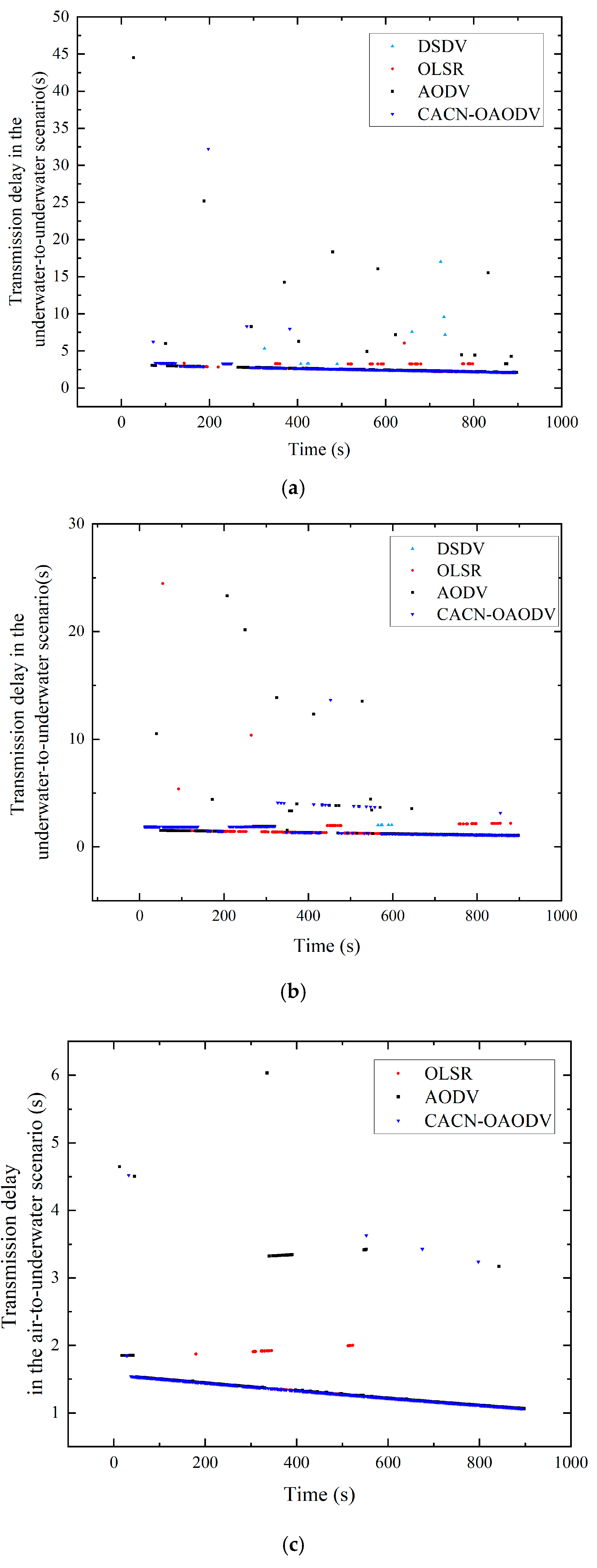
The delay for the three scenarios is given in
Figure 7, and the average delay is summarized in
Table 2. In the underwater-to-underwater scenario, the average delay of OLSR is approximately 0.48 s lower than that of AODV. From
Figure 7, it can be observed that OLSR is more stable compared to AODV and DSDV. In the underwater-to-air scenario, the average delay of OLSR is about 0.27 s lower than that of AODV, and in the air-to-underwater case, it is around 0.16 s lower. However, with DSDV, many packets failed to reach the destination nodes, and this is not reflected in the average delay. Thus, the end-to-end delay for DSDV is not meaningful.
Figure 7 shows that AODV has many more instances of high delay compared to OLSR. OLSR exhibits more stable delay performance compared to AODV in certain scenarios. In contrast, AODV is an on-demand routing protocol that checks for an existing route to the destination node before sending data. If no route exists, the data are cached, and a routing request is initiated to discover a path, which increases the transmission delay.
Although the AODV routing protocol provides good network performance, there are major issues that necessitate improvements. First, each route in the routing table of every node has a lifetime. If a route exceeds its lifetime, the source node must initiate a routing request. In addition, nodes not on the transmission path broadcast Hello messages, which increases traffic on the underwater acoustic channel and so reduces the PDR of the acoustic–radio collaborative network.
The AODV routing protocol is based on the principle of minimum hop count. Since the speed of radio waves is much higher than that of underwater acoustic waves, the minimum hop count in the acoustic–radio collaborative network does not necessarily correspond to the minimum delay. Therefore, the speed of the waves should be considered to reduce the overall delay. The nodes in the acoustic–radio collaborative network are mobile, which can lead to broken communication links. Once a link breaks, the route must be reestablished, which affects the overall network transmission efficiency. Therefore, when establishing routes, the distance between nodes should be considered to improve the performance.
The issues identified with the AODV routing protocol in cross-medium acoustic–radio collaborative networks are excessive route notification packets, high delay, and unstable links. To address these issues, we propose an Optimized AODV protocol for the Cross-medium Acoustic–Radio Collaborative Networks (CACN-OAODV). It is based on an optimized mechanism for distance-aware stability. The improvements to AODV are given below.
First, to reduce the number of route notification packets, after a route is established, nodes no longer set a route expiration time. Instead, nodes determine whether a route is invalid based on whether they receive periodic HELLO messages from neighbors. Second, surface cross-medium nodes specify the relevant communication devices for data transmission based on the destination node type. When the underwater acoustic communication device of a cross-medium node receives a routing request message, if the destination is an aerial node, the request is forwarded directly via the buoy radio communication device, and the underwater acoustic communication device does not forward it. This reduces underwater overhead. If the destination is an underwater node, two scenarios are considered. If the surface cross-medium node receives a routing request from an underwater node, it forwards the request using its radio communication device, and if the radio communication device of the surface cross-medium node receives a routing request, it forwards the request simultaneously via both the underwater acoustic and radio communication devices. Third, after a node receives a routing reply and establishes a route, it is configured to periodically send HELLO messages for route maintenance, while other nodes that have not established routes do not send HELLO messages. This reduces the overall packet transmission and thus the communication burden. Finally, after an underwater destination node receives a routing request, it sends two consecutive RREPs to the source node to improve the success rate of route establishment over unreliable communication links.
In the RREQ packet, a lifetime is set, which represents the maximum number of hops the routing request packet can traverse. If the number of hops this packet has traversed exceeds this maximum, it will not be forwarded. Due to the significant difference in speeds between underwater acoustic and radio waves, the minimum hop count is converted into a minimum delay using a weight applied to the hop numbers. The weight of the hops using radio transmission is lower than the weight of the hops using underwater acoustic transmission. The hop count for a routing request is then
a is the weight of a hop using underwater acoustic transmission, Hopuw is the number of underwater hops for the routing request, b is the weight of a hop using radio transmission, and is the number of hops using radio transmission.
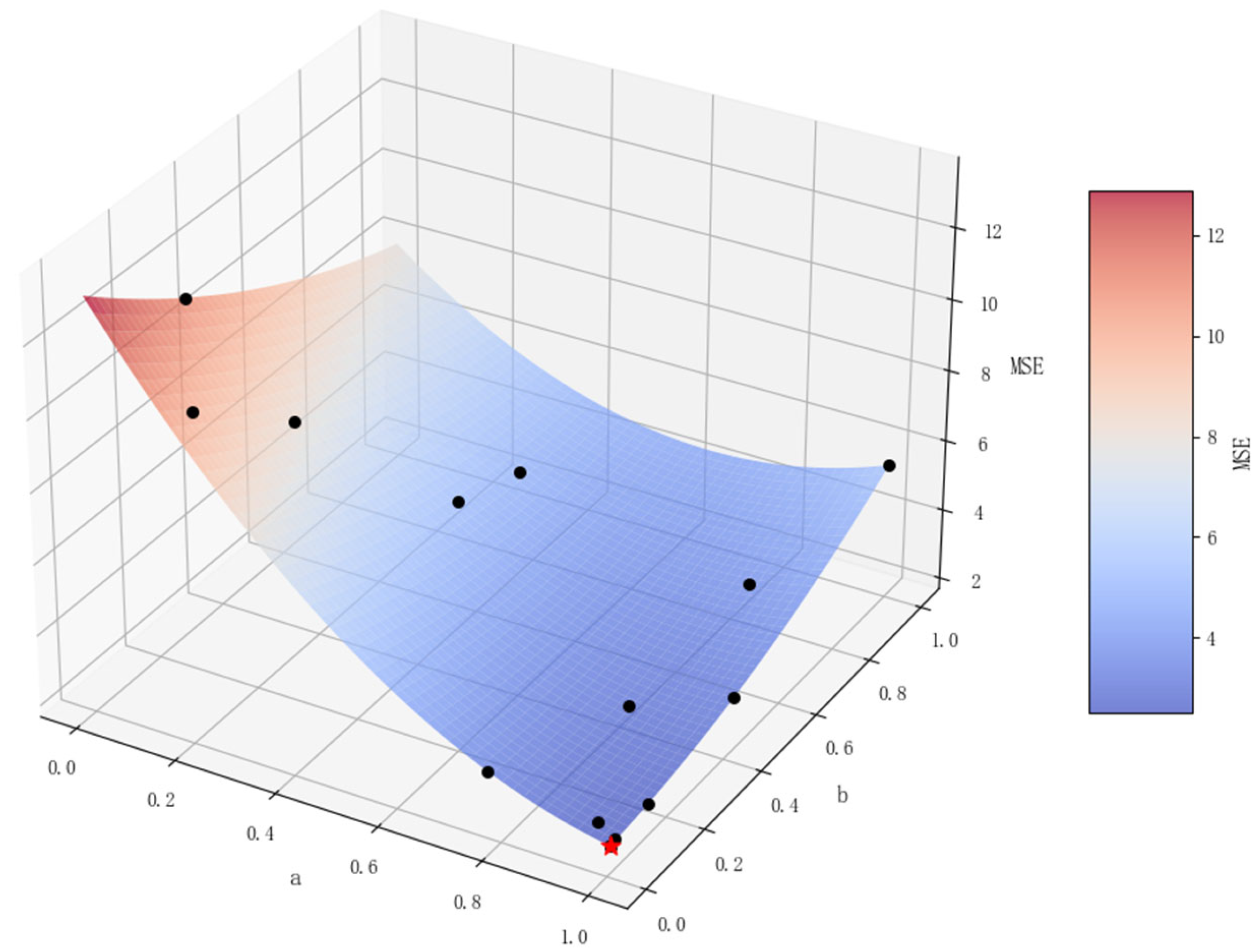
Bayesian optimization [
28] is employed to determine the weights a and b. This involves continuously updating the posterior probability distribution of the parameters to find the optimal solution. The goal is to minimize the difference between the predicted routing delay and the actual routing delay. Therefore, the objective function is the Mean Squared Error (MSE) given by
n is the number of samples,
delayi is the actual transmission delay of the
ith sample,
is the underwater acoustic hop count of the
ith path,
is the radio hop count of the
ith path, and a and b are the parameters to be optimized with 0 < a ≤ 1 and 0 < b ≤ 1. The optimization is illustrated in
Figure 8. This shows that after 25 iterations, the optimal weights are a = 1.0 and b = 0.01, and the MSE is 2.46.
A link stability factor is employed for underwater acoustic data transmission based on the distance between adjacent nodes and is given by
d is the distance between the nodes, R is the maximum communication radius, and ε × R is the critical communication distance. Beyond the critical distance, the communication link is considered to be unstable and may result in packet loss. The parameter ε was determined via simulation of underwater transmission scenarios to obtain the network PDR.
The Aggregate Link Stability Factor (ALLRQ) is defined as the sum of all single-hop link stability factors (RQs) on the specified path
where n is the number of hops. The Average Link Quality (AVGRQ) is
A higher AVGRQ indicates better link quality. Routing requests need to include previous hop information, so the message format is modified as follows: the last hop geographic location information and ALLRQ are added to the RREQ message, and AVGRQ is added to the RREP message.The modified RREQ message format is detailed in
Table 3, and the modified RREP message format is shown in
Table 4.
Although Equations (17)–(19) explicitly use distance the impact of SNR and node mobility is intrinsically captured through the threshold . We set based on simulation analysis to represent the boundary where the SNR remains above the decoding threshold. By restricting route selection within this distance, the protocol effectively accounts for link degradation caused by relative node movement (2–3 m/s) and acoustic noise.
- (A)
Protocol Design
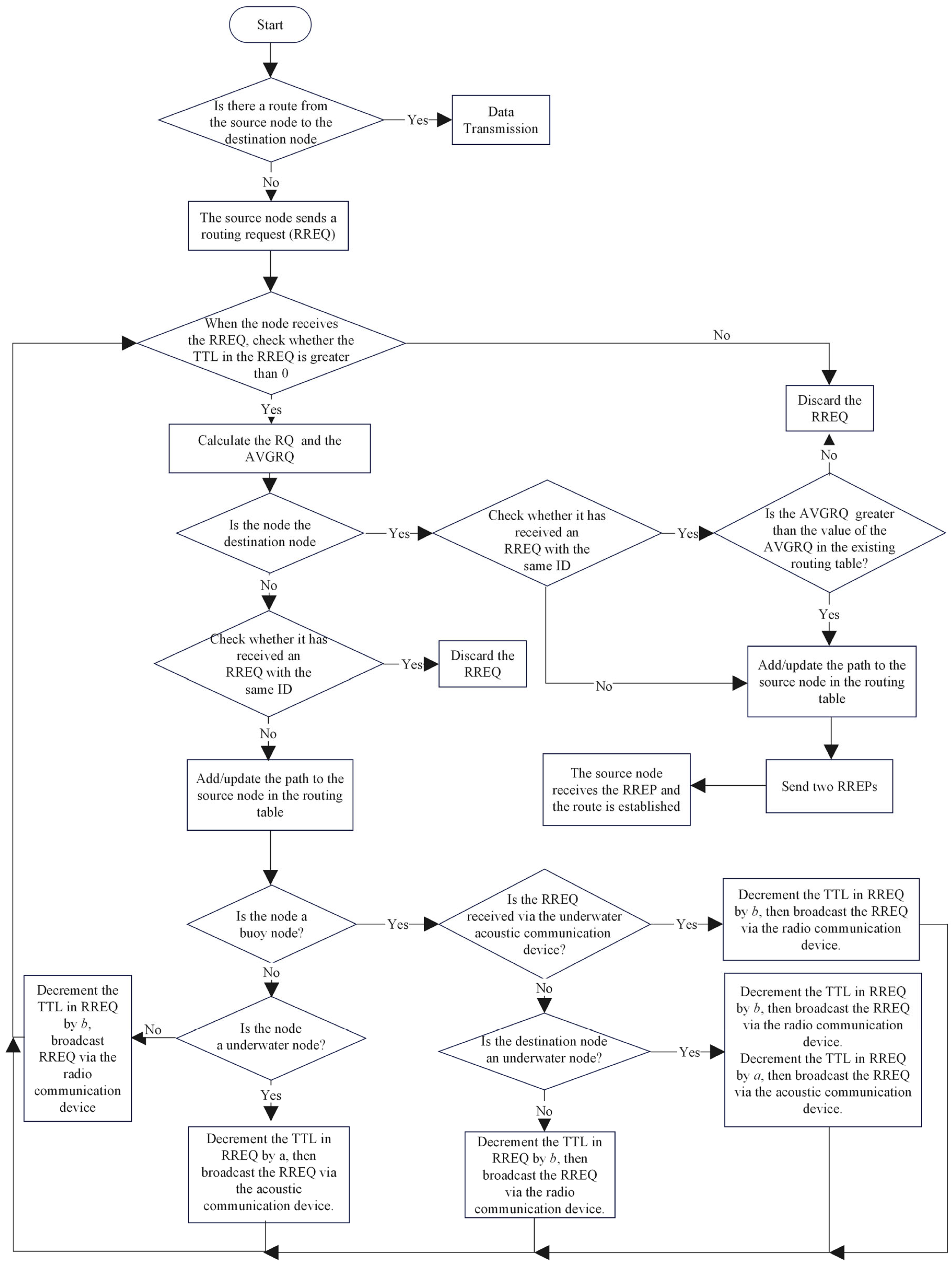
The CACN-OAODV route discovery process is illustrated in
Figure 9.
The route discovery steps are as follows.
Verify the availability of a valid route to the destination node. If such a route exists, data transmission is initiated. Otherwise, an RREQ message containing the Time to Live (TTL) is broadcast.
Upon receiving an RREQ, an intermediate node first verifies if TTL > 0. If this is satisfied, the node calculates the distance of the previous hop, computes the hop link RQ, adds this to ALLRQ in the RREQ, and divides by the hop count to obtain the new AVGRQ.
The node determines whether it is the destination node. If yes, proceed to Step 4; otherwise, go to Step 5.
The node checks whether an RREQ with the same ID has been received. If no, it stores the path to the source node in the routing table and sends two RREPs to the source node. If such an RREQ exists, the node evaluates whether the current AVGRQ exceeds the existing value in the routing table. If yes, the path to the source node is stored or updated in the routing table; otherwise, the RREQ is discarded.
The node checks whether it has received a duplicate RREQ. If yes, the RREQ is discarded. If no, the node stores the reverse path to the source in its routing table and, depending on its node type, proceeds to Step 6 or Step 7.
For buoy nodes, the forwarding method is determined based on both the receive communication device of the RREQ and the destination node type. If the RREQ is received via an underwater acoustic communication device, the TTL is decremented by b, and the message is forwarded solely via the radio device.
If the RREQ is received from a radio device and if the destination node is not an underwater node, TTL is decreased by b, and it is forwarded via radio only, but if the destination node is an underwater node, TTL is decreased by b and a, respectively, and it is forwarded via both the radio and underwater acoustic communication devices.
For non-buoy nodes, if it is an underwater node, TTL is decremented by a, and the RREQ is forwarded via the underwater acoustic communication device. If it is an aerial node, TTL is decremented by b, and the RREQ message is forwarded via the radio communication device.
The above steps are repeated by the next-hop node upon receiving the RREQ.
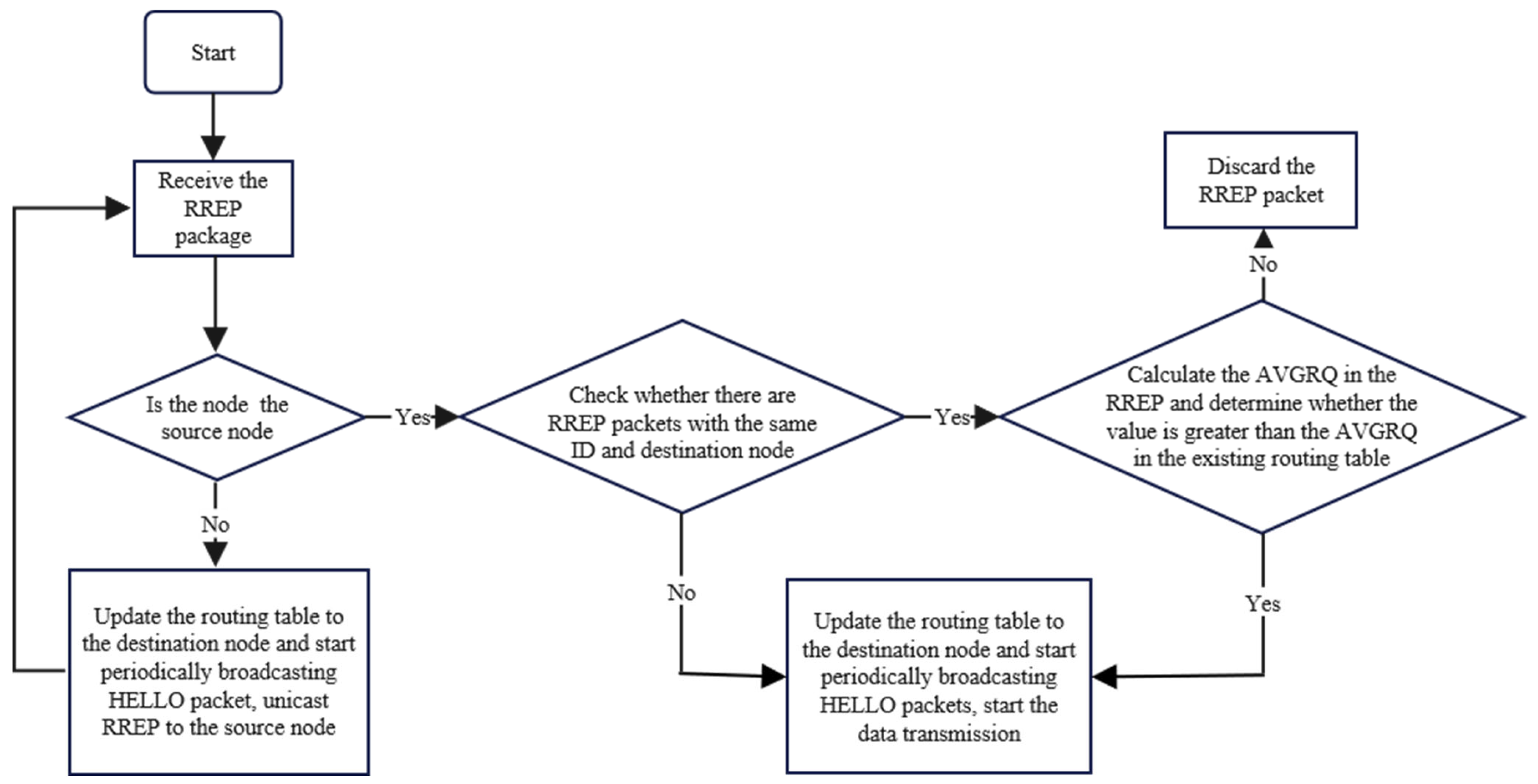
The CACN-OAODV route reply steps are illustrated in
Figure 10.
The route reply steps are as follows.
When a node receives an RREP message, it first checks whether it is the source node. If no, proceed to Step 2; otherwise, go to Step 3.
The node updates the path information to the destination node in its routing table, initiates periodic HELLO message broadcasts to maintain neighbor relationships, and then forwards the RREP message to the source node via unicast.
Check whether there is a duplicate RREP message in the message list with the same ID and destination node. If no, proceed to Step 4; otherwise, go to Step 5.
Update the routing table, broadcast HELLO messages periodically, and begin data transmission.
Calculate the AVGRQ for the received RREP and compare it with the existing AVGRQ value in the routing table. If the new value does not exceed the current value, discard the RREP message; otherwise, go to Step 6.
The node updates its routing table, enables periodic HELLO packet broadcasts, and begins data transmission.
The specific weights are derived via Bayesian optimization to minimize the Mean Squared Error (MSE = 2.46) of end-to-end delay. A weighted TTL is superior to a fixed delay budget (in seconds) because it dynamically accommodates the speed difference between acoustic and radio waves, preventing the premature discarding of valid high-latency underwater routes.
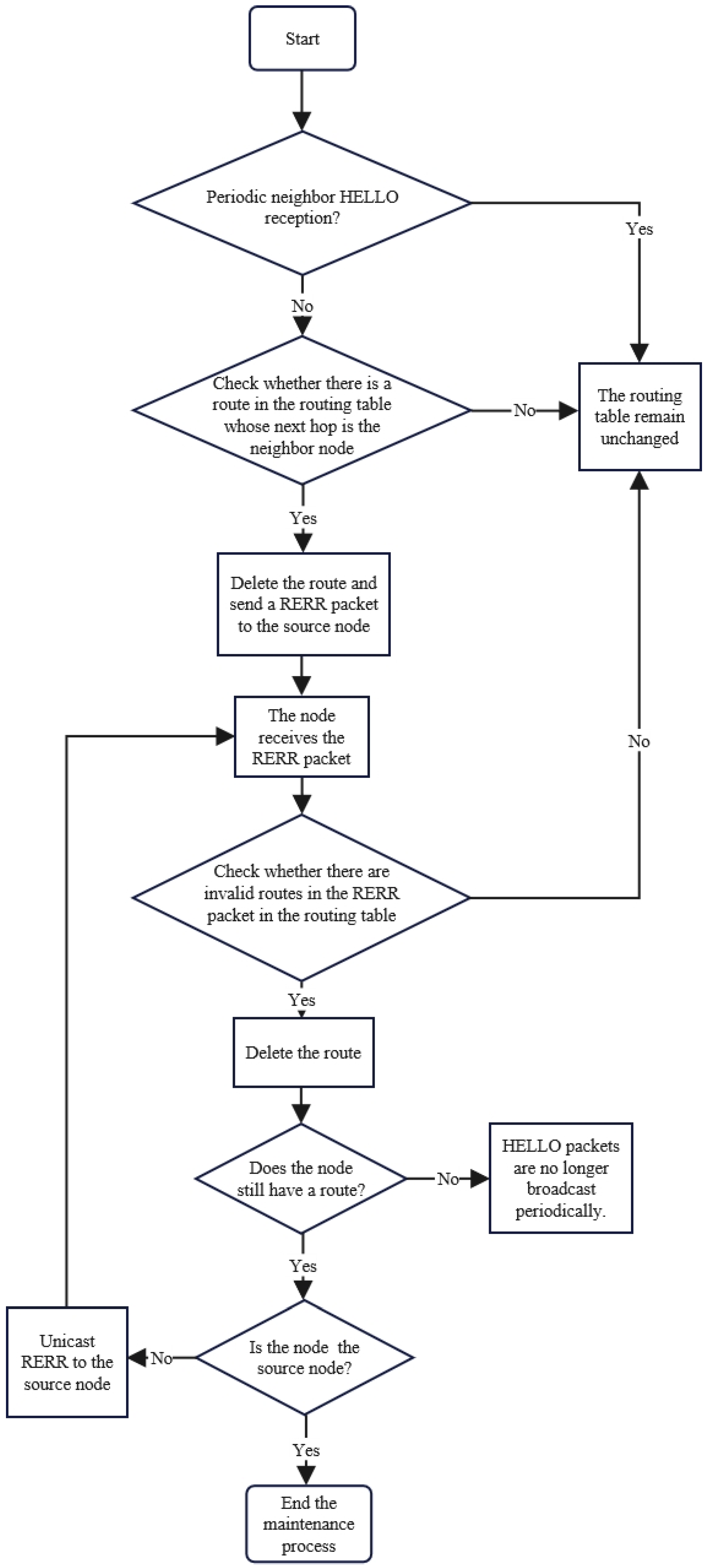
After a route is established, all nodes on the path regularly broadcast Hello packets and begin routing maintenance. The CACN-OAODV route maintenance steps are illustrated in
Figure 11.
The route maintenance steps are given below.
A node monitors whether Hello messages are received periodically from a neighboring node.
If Hello messages are received normally, the routing table remains unchanged. If Hello messages are not received, the node verifies whether any route in the routing table uses this neighbor as the next hop. If no route exists, maintenance ends. Otherwise, the corresponding routes are deleted from the routing table, and RERR messages are transmitted to the associated source nodes.
If an RERR message is received, the node checks its routing table for routes corresponding to this notification. If routes are found, they are removed.
The routing table is assessed. If it is empty, Hello message broadcasts are ended. If routes remain, determine whether you are the source node. If no, send RERR messages to the source nodes. Otherwise, terminate route maintenance.
- (B)
Proposed protocol evaluation
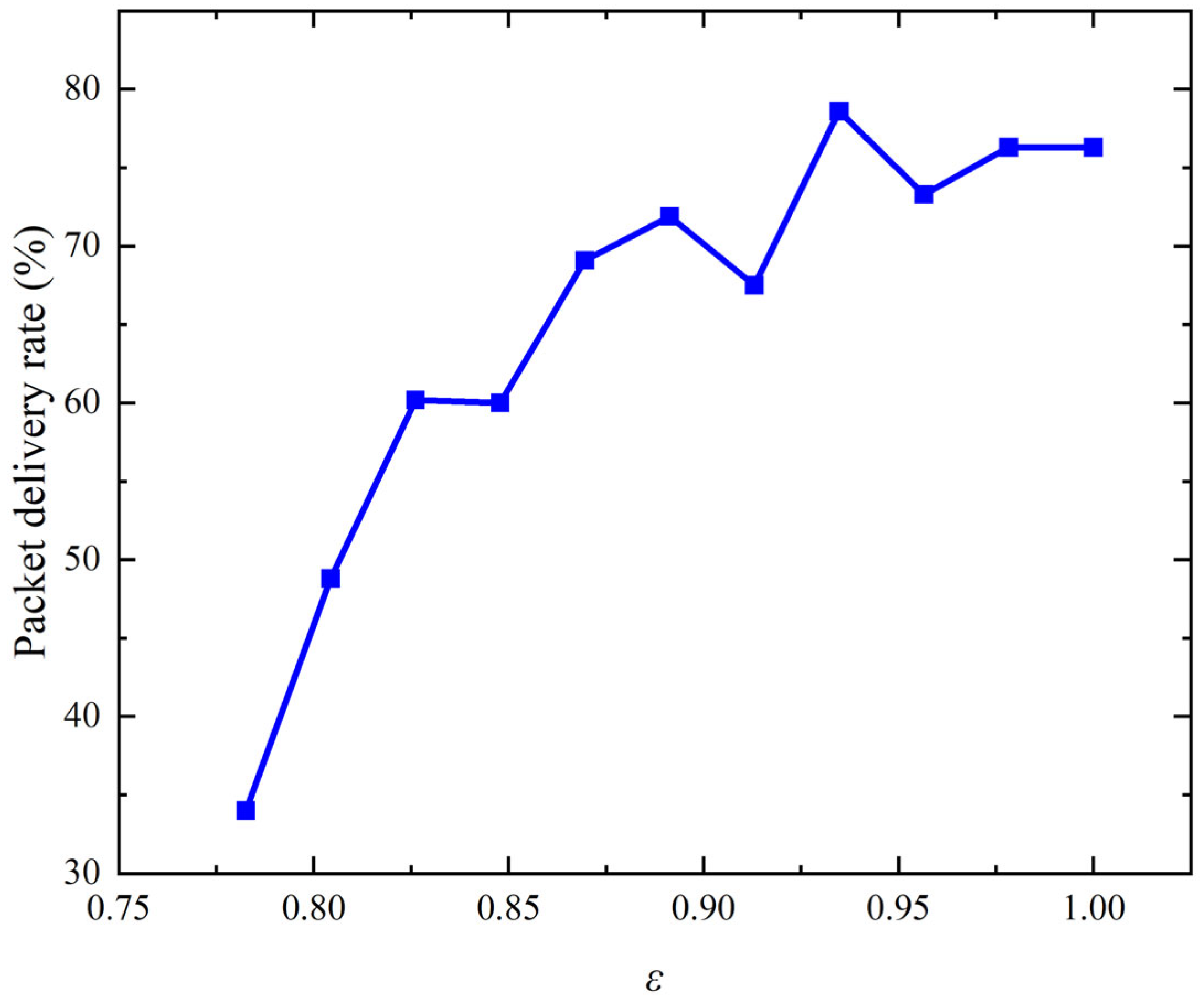
To determine ε, data transmission in underwater-to-underwater scenarios was simulated and the PDR obtained. The results in
Figure 12 show that, in general, as ε increases, the PDR also increases. When ε is 0.94, the PDR reaches its maximum, so ε is set to 0.94.
Regarding duplicate packets, nodes discard redundant RREPs unless the new improves by more than 10%. While the dual RREP mechanism increases the acoustic control overhead by approximately 10%, it leads to an overall reduction in total control traffic by significantly decreasing the frequency of route reconstructions.
We utilize on-demand HELLO packets with a 2 s interval. To handle intermittent packet loss in acoustic channels, a 1 s hysteresis timer is implemented. A route is only marked as stale if no HELLO or data packets are received from the next hop after three consecutive intervals and a secondary RREQ probe fails.
To limit overhead, we implement the following: (1) link quality pruning, discarding RREQs from unstable links; (2) duplicate handling, where a duplicate RREP is only accepted if its is higher than the current path; and (3) adaptive RREP, where the destination sends two consecutive RREPs to improve success rates in lossy acoustic channels. This increases local control bytes by ~10% but reduces the global collision rate to below 8% by preventing route storms.
All network simulations in this paper were implemented on the Network Simulator 3 (ns-3, Version 3.28, developed and maintained by the ns-3 project community, hosted by the University of Washington, Seattle, WA, USA), with the Aqua-Sim Next Generation (Aqua-Sim NG, Version 1.0, UWSN Lab, University of Connecticut, Storrs, CT, USA) module for underwater acoustic channel modeling. Simulation data processing was performed using MATLAB (R2023a, MathWorks Inc., Natick, MA, USA), and all figures in the manuscript were plotted using Origin (Version 2023b, OriginLab Corporation, Northampton, MA, USA).