1. Introduction
With the continuous increase in the density of maritime navigation, the navigation environment for ships has become more complex, and ship safety has become a key issue of concern in the world today. The investigation results of maritime accidents show that the professional quality and driving ability of crew members are of great significance to ensure the safety of ships and cargo [
1]. Traditional ship driving training mainly focuses on maritime internships, which not only have a high economic cost but also cause serious pollution. Maritime internships are even more lacking in training scenarios, making it difficult to realistically and comprehensively reproduce various complex maritime environments [
2], and thus unable to meet the current requirements for crew training. The use of a six-degree-of-freedom ship driving simulator for ship driving training is not restricted by factors such as time, climate, and site and has the advantages of low cost, high efficiency, good safety, and energy conservation [
3]. Therefore, it is an urgent issue to establish a comprehensive, efficient, and environmentally friendly training method to improve the skill level and strain capacity of ship drivers and then improve the safety of maritime traffic.
Ship simulation driving equipment can simulate the real ship driving environment. By operating the equipment and virtual environment, it can simulate and reproduce the operation logic and motion response of the actual ship. Ship simulators are generally equipped with simulation control devices, simulation computer devices, and visual simulation devices. Through numerical calculation and real-time simulation models, the driving simulator can simulate the ship’s motion response to control inputs and provide visual and dynamic feedback to the operator through the instruments and motion systems in the cockpit. Varela et al. [
4] constructed a 3D desktop ship simulation system, which utilized an image processing unit to enhance the real-time performance and authenticity of the simulation and integrated the calculations of ship motion and wave motion. Katie Aylward et al. [
5] utilized virtual reality technology to study the ship operation training for seafarers in the Arctic waters. Ham et al. [
6] developed a ship simulation system by introducing a six-degree-of-freedom motion platform, studied wave motion and ship motion, and ultimately integrated it into a six-degree-of-freedom platform driving simulator.
In the abovementioned research on virtual ship motion simulation, the existing methods for simulating the motion attitude of virtual ships are still not realistic enough in terms of the simulation effect of the driver’s body sensation during the ship’s handling response process. The existing methods are more reflected in the accuracy of the ship motion research, but the ship motion characteristics in the process of ship driver’s somatosensory reproduction have not been widely studied. It is necessary to make targeted improvements in response to the body sensation reproduction requirements of the driving simulator.
To reproduce the jolting sensation of the driver during the ship driving process, existing ship driving simulators generally take the acceleration and angular velocity generated by the actual or virtual ship movement as input and realize the body sensation reproduction of the ship driver on a six-degree-of-freedom motion platform. However, due to the limited travel of each degree of freedom on the six-degree-of-freedom platform, it is almost impossible to directly reproduce the motion state of the ship. To overcome the above problems and restore the body sensation of ship drivers as much as possible within the limited six-degree-of-freedom travel, some related studies have been conducted. Min-Chul Kong et al. [
7] designed a virtual simulation scheme for ships, which can simulate the maritime perception situation and generate virtual perception data. Nehaoua et al. [
8,
9] extracted the optimal parameters of the filter using the gradient descent method, taking into account the displacement, velocity limit, and motion sensing error of the moving platform, and applied it to the two-degree-of-freedom platform. This improved algorithm makes it difficult to determine the fitness function and weight parameters in a timely and accurate manner according to the changing input, and there are many design parameters and differential equations. It has disadvantages such as a large computational load and a long computing cycle. Casas et al. [
10,
11] incorporated genetic algorithms into the optimal filter and added motion compensation signals to the motion simulator, thereby enhancing the authenticity of motion. Nehaoua et al. [
9,
12] compared classical, adaptive, and optimal washing algorithms in a small driving simulator. They believed that the classical washing algorithm had the characteristics of a simple structure and high performance. Casas et al. [
13] also optimized on the basis of the classic washing algorithm, improving the motion fidelity and the utilization rate of the platform’s motion space. Chen et al. [
14] compared the perception of motion between the classical washing algorithm and the adaptive washing algorithm. Han Lei, Xiong Xiaohua et al. [
15,
16] incorporated the human sensory model through the classical washing algorithm and applied it to the flight simulator for training flight pilots. LI Panpan et al. [
17] designed a new optimal control washing algorithm, which improved the fidelity of motion simulation by reasonably adjusting the weight matrix. Chen Weixing et al. [
18] introduced analog control to process motion signals, maintaining the authenticity of the motion signals and enhancing the reproduction effect of the motion platform on the motion signals. Wang Xiaoliang et al. [
19] applied fuzzy control to the train simulator washout algorithm and focused on improving the low-frequency acceleration, thereby verifying the fidelity of the motion washout algorithm and reducing the phase error caused by fixed parameters. Wang Hui and Zhu Daoyang et al. [
20] established fuzzy control based on the human motion sensory threshold for the phase delay problem. Li Ruzhou et al. [
21] improved by applying the fuzzy algorithm to the adaptive motion washout algorithm, enhancing the parameter adjustment ability and thereby improving the motion reproduction effect. Not only will the external conditions affect the ship’s motion, but also the ship’s design and construction standards, fin stabilizers, and other ship equipment will affect the ship’s motion characteristics. Diatmaja et al. [
22] and Rahmaji et al. [
23] have studied the relevant influence laws.
To sum up, the existing research can only improve the execution effect of the six-degree-of-freedom platform under a single speed and acceleration command to a certain extent, but it cannot provide a realistic sense of continuum. In this paper, a six-degree-of-freedom motion model of a virtual ship is constructed by using the idea of the MMG separated ship motion model and the wave simulation method. The numerical values of the body-sensing characteristics of the corresponding virtual ship in the motion state are provided. The driver’s body-sensing reproduction is realized by using the human perception model, and the effectiveness of the method is verified through experiments.
In this article, the semicircular canal model and otolith model are used to describe the human body’s perception of acceleration. The human acceleration perception model has been successfully applied to the six-degree-of-freedom platform washout algorithm, which improves the realism of the six-degree-of-freedom platform in simulating ship drivers’ turbulence. At the same time, the traditional washout algorithm is improved and applied to the six-degree-of-freedom platform. The research described in this article also has limitations. If the simulated environment is complex, sea conditions and the ship tonnage are small, and the heave motion is obvious, the heave sensation cannot be restored, and further research is needed in the future.
The three main contributions of this study are as follows.
Based on the MMG separated ship motion model and the FFT wave simulation method, the ship attitude simulation under low sea conditions is realized. Compared with the previous ship motion model, the improved method proposed in this paper can obtain the six-degree-of-freedom motion data of the ship with more obvious acceleration characteristics. Under the premise of reasonable assumptions, it can improve the operation efficiency of multi-ship simultaneous simulation and is more suitable for running in the navigation simulator.
The human sensory deception mechanism is established by integrating the semicircular canal model and the otolith model. The perception parameters are incorporated into the washing algorithm to effectively simulate the human body’s perception of ship movement and enhance the realism of the driver’s body sensation in the simulated environment. Compared with the existing six-degree-of-freedom virtual navigation equipment, this research can increase the continuity of the somatosensory simulation in the limited six-degree-of-freedom platform motion range and overcome the problem of the unreal human in the process of left-right, front-end, and back displacement. However, in the actual composition of ship navigation, the continuous motion of the above displacement often occurs easily.
By optimizing the structure of the classic washing algorithm and combining the sensory model output to control the six-degree-of-freedom platform, experiments show that the correlation between the platform motion data and the actual ship data is as low as 81.2%, verifying the effectiveness of the body-sensing reproduction.
The rest of this article is organized as follows: In
Section 2, the ship motion and wave environment are modeled. In
Section 3, the proposed body-sensing reproduction method is introduced. In
Section 4, the established method is tested and verified under different conditions. In
Section 5, the conclusion is stated.
2. Modeling of Ship Motion and Extraction Method of Somatosensory Characteristics
2.1. Ocean Wave Simulation
The impact of waves on ship attitude is critical to ship attitude simulation. In a virtual ocean scenario, the motion of a virtual ship is primarily influenced by virtual waves. To enhance the realism of virtual ship attitude simulation, a virtual wave model is established in this paper through the superposition of sine and cosine waves, with the superposition value computed by the Fast Fourier Transform (FFT) algorithm.
In the process of wave simulation, it is divided into mechanical feature simulation and visual feature simulation. The key step of wave simulation is to simulate the positions of discrete force points and visual points. Firstly, visual simulation is required, followed by mechanical simulation. In this model, wave height is treated as an independent variable, representing the height of point
at time
, denoted as
;
is a point on the horizon, expressed as
. The calculation method is shown in Formula (1) as follows:
refers to a point on the horizon, expressed as ; is the height of this point at time , obtained by superposing a series of sine waves; is a two-dimensional vector, i.e., , , ; and are integers are dimensionless intermediate variables. Similarly, taking N and M as dimensionless intermediate variables, they can be calculated from n and m. and . After the FFT process, the height of the discrete point on the sea surface can be obtained.
When only the effect of wind on waves is considered, the wave spectrum can be represented by the well-known empirical Phillips spectrum function as follows:
, is the gravitational acceleration; is the wind speed; is the wind direction; is a constant; is eliminate waves that are perpendicular to the wind direction. It is found in the experiment that when the wave number is very large; the convergence of this formula is very poor. Therefore, a correction term is multiplied by the Phillips spectrum formula, where .
From this, the Fourier wave amplitude of the wave can be obtained as follows:
where
and
are mutually independent Gaussian random numbers,
. When the propagation frequency
is known, the Fourier wave amplitude at time
is obtained as follows:
only the vertical offset of each point on the horizontal plane is discussed in this formula.
Similarly, the horizontal offset is obtained by the derived Fourier wave amplitude value, as follows:
therefore, the position of each grid point
on the horizontal plane is
, where
is the proportional coefficient; the height is
as derived previously.
2.2. Ship Motion Model
Before deriving the ship motion equation, the following assumptions are made:
- (1)
Assume that the environmental condition is infinite water depth.
If the water depth in the navigation area of a ship is too shallow, it will cause serious shallow water effects, increasing the navigation resistance and additional mass of the ship. The ship discussed in this article is a steel sea vessel, which mostly navigates in dedicated waterways or open waters. Therefore, the influence of shallow water effects is ignored, and wireless water depth is assumed.
- (2)
The ship is a bilaterally symmetric rigid body with constant mass, and its geometric shape does not change.
When a ship is sailing at sea, regardless of the material used to make its hull, it will inevitably undergo small deformations when subjected to wave impacts and the influence of its own propulsion system. Additionally, the weight of the ship’s hull will change with the attachment of marine organisms, which will interfere with the ship’s motion characteristics. But the abovementioned interference is very small and will form over a long period of time. To simplify the operation, the reasonable assumption mentioned above is made according to the usual practice.
- (3)
The influence of waves on the propeller force and the rudder force is not considered.
Waves have a negligible impact on the hydrodynamic performance of ship propellers, and this small influence was already considered in the design of ship propellers. Therefore, this article makes reasonable assumptions about this situation and ignores this influence.
- (4)
The changes in hydrodynamic derivatives caused by wave action during movement are not considered.
The influence of hydrodynamic derivatives on ship motion is minimal, especially for large steel vessels, which can be completely ignored. Therefore, this article makes reasonable assumptions and ignores the changes in hydrodynamic derivatives caused by wave action during ship movement.
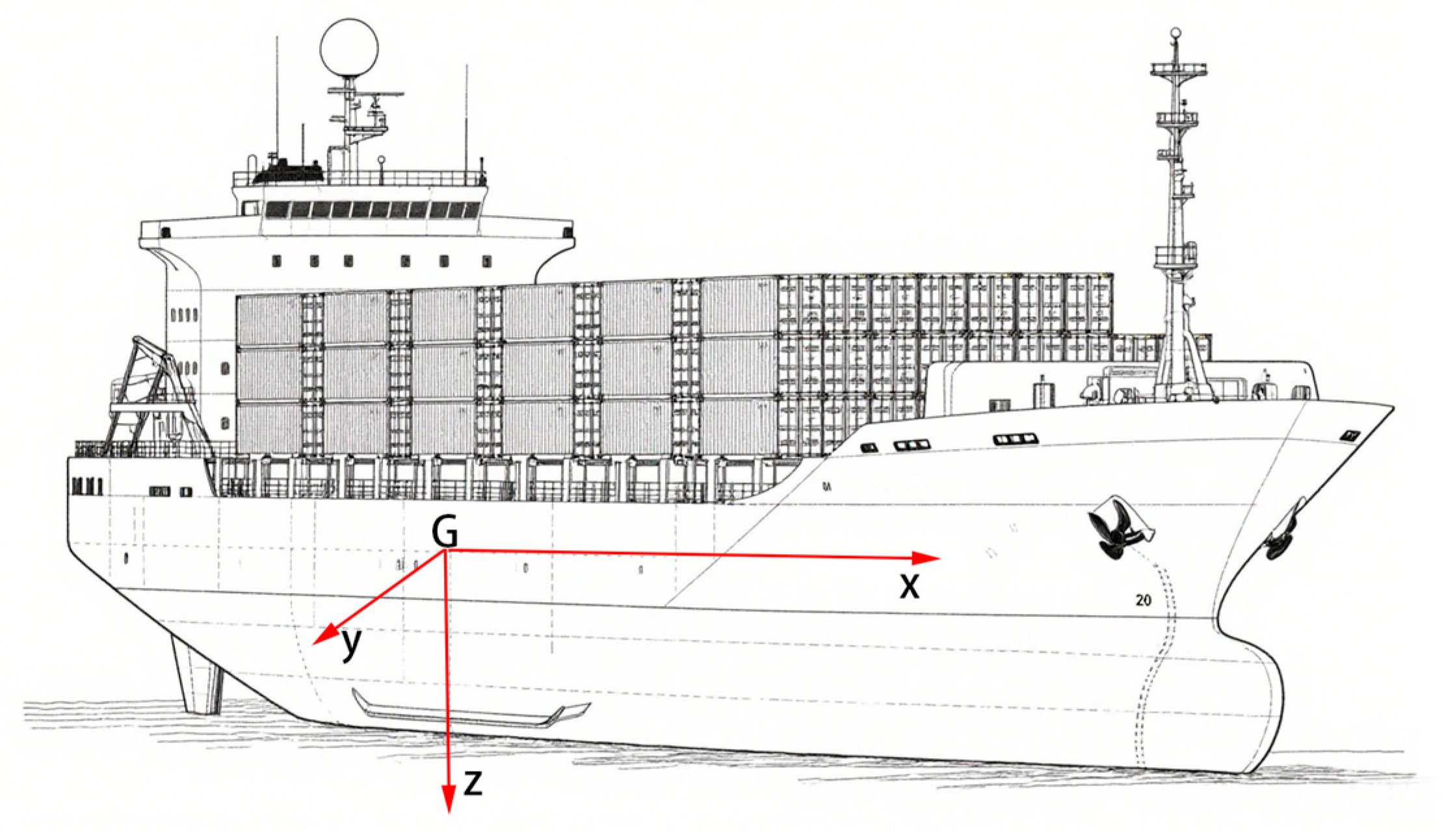
According to the kinetic energy theorem and momentum theorem, the forces and torques acting on the ship can be expressed as components along the x, y, and z axes, respectively. The positive direction of the
x-axis points toward the bow of the ship; the positive direction of the
y-axis points toward the starboard side of the ship; the
z-axis is perpendicular to the hull, with its positive direction pointing toward the bottom of the ship. The coordinate system is illustrated in
Figure 1.
2.3. Feature Extraction of Body Sensation
2.3.1. Solution of Hull Stress
The calculation of the added mass and added moments of inertia of the inertial fluid forces acting on ships is usually based on fluid dynamics theory and numerical calculation methods. The three-spectrum multivariate regression analysis method is adopted in this paper, and the ship planar added mass estimation formula is obtained as follows:
in Formula (6),
is the coefficient, which is taken according to the actual ship size and mass; m is the mass of the ship; B is the width of the ship; L is the length of the ship; d is the draft of the ship.
In the torque of inertia of ship accessories, complex factors need to be considered. Generally, the torque of inertia of the ship itself and the torque of inertia of the accessories are mixed and estimated using an empirical formula as shown below:
in Formula (7), generally
.
is the coefficient, which depends on the type of ship and can be estimated by Formula (8) as follows:
The additional torque of inertia of the ship’s pitch and the added mass of the heave can be estimated according to the following empirical formula:
in Formula (9),
is the waterline coefficient of the ship;
is the prismatic coefficient of the ship.
The viscous hydrodynamic behavior of a ship in still water is mainly influenced by three aspects: the geometric characteristics of the ship itself, the fluid characteristics of the flow field in which it is located, and the motion state of the ship. First, the interaction between the hull and surrounding fluid is directly determined by the geometric characteristics of the ship, including shape parameters such as length, breadth, depth, mass, and block coefficient. The intensity of the resistance and fluid forces acting on the hull during its motion in the fluid is directly determined by the size and shape coefficients of the ship. Second, the intensity of the viscous fluid forces is significantly influenced by the physical properties of the fluid, such as fluid density, viscosity coefficient, gravitational acceleration, and surface tension coefficient. Finally, the trajectory of the ship in water is determined by the motion state of the ship, including ship speed, linear acceleration, angular velocity, and steering, thereby determining the relative motion between the fluid and the hull. Combined with the Guidao Model [
22], the dynamic force and torque of viscous fluid can be approximated as follows:
In Formula (10), is the straight-line resistance; , , and are the longitudinal fluid dynamics caused by pitch and yaw; , , , and are linear fluid forces and torques; , , , , , and are nonlinear fluid forces and torques.
- (1)
Longitudinal fluid dynamic coefficient
The calculation of the straight-line resistance coefficient is an important part of the mathematical model of ship motion. However, it is computationally complex, and theoretical analysis is generally adopted for approximate calculation at present, which can be expressed as follows:
In Formula (11), S is the wet surface area of the hull, which can be estimated by the Songhai formula , is the displacement volume; is the waterline length; k is the area coefficient, which is determined by the ship’s width B and draft d; is the total straight-line resistance coefficient.
The total straight-line resistance coefficient
approximately includes the friction resistance coefficient and the residual resistance coefficient C
r, which can be expressed as follows:
In Formula (12),
is calculated by the following formula proposed by ITTC:
is the Reynolds number, which is expressed as .
The fluid dynamic derivatives
,
, and
are calculated as follows:
- (2)
Lateral fluid dynamic
The approximate estimation formula for linear fluid dynamic derivatives is as follows:
in Formula (17),
is the draft of the ship;
is the average value of the ship’s draft;
is aspect ratio. The influence of trim
is not considered in this paper, and
is set to 0.
The approximate estimation formula of nonlinear fluid dynamic derivative is as follows:
- (3)
Rolling hydrodynamic torque
According to Formula (19), the viscous fluid dynamics of rolling motion can be expressed as follows:
In Formula (20), , where is generally taken as 0.06.
The
Z-axis coordinate Z
H of the point of action of the lateral fluid dynamic Y
H is as follows:
In Formula (21), Z
g is the height of the ship’s center of gravity from the baseline; a is the height coefficient of the lateral force action point.
- (4)
Heave and pitch fluid dynamic torque
By analyzing the second-order linear differential equations for the coupling of pitch and heave motions in regular waves, the viscous fluid dynamics and torques associated with heave and pitch motions can be obtained as follows:
The parameters of the heave and surge torques can be obtained from the empirical formula of Tasai [
24], which can be expressed as follows:
where C
w is the waterline coefficient; C
p is the prismatic coefficient;
.
2.3.2. Calculation of Propeller Thrust Characteristics
During the movement of a ship, the propeller generates thrust by overcoming the resistance of water, becoming one of the main sources of power to propel the ship.
Forces induced by the propeller are provided by the following formula:
In the above formula, Xp is the axial thrust of the propeller; Yp is the lateral force; Np is the ship bow torque. Under normal circumstances, the lateral force and yawing torque generated by the propeller are usually small. To simplify the calculation, Yp and Np are set to 0. Among these parameters, is the density of water; n is the propeller rotational speed; tp is thrust deduction coefficient; Dp is the propeller diameter; is the propeller thrust coefficient, which is calculated by a second-order polynomial of the propeller advance ratio .
The propeller thrust reduction coefficient t
p can be estimated according to the Hankshire formula, which is as follows:
In Formula (26), C
p is set to 0.65 in this paper. The advance coefficient J
p is specifically expressed as follows:
where n still denotes the propeller rotational speed. The calculation formula for the wake coefficient is as follows:
is the drift angle at the propeller, expressed as . is the drift angle at the center of gravity of the ship, and r is the radius of the propeller.
2.3.3. Calculation of Rudder Blade Force Characteristics
During ship movement, rudder force is also an important component of ship maneuvering. It plays a decisive role in the direction adjustment and attitude control of the ship.
The rudder force and torque are provided by the following:
In Formula (29), FN is the normal pressure acting on the rudder blade surface; tR is the rudder drag deduction coefficient; is the rudder angle; aH and xH are the coefficients characterizing the hydrodynamic interaction between the hull and the rudder; xR and ZR are the longitudinal and vertical distances from the rudder force to the center of gravity of the ship, respectively.
The normal pressure F
N acting on the rudder blade surface is calculated as follows:
where A
g denotes the area of the rudder blade. U
R is the effective inflow velocity at the rudder, and its specific formula is as follows:
U
R is the effective longitudinal velocity of the incoming flow in the rudder, expressed as follows:
In Formula (32), h is the height of the rudder,
; u
p is the effective flow velocity into the paddle, expressed as
; k is the rudder speed factor; s is the slip of the paddle.
is the effective lateral velocity of the incoming flow to the rudder, and the formula is as follows:
is the effective angle of attack of the incoming flow in the rudder, and the formula is as follows:
In Formula (34),
is the coefficient of rectification on the hull. In the process of analyzing the force on the rudder, the roughness of the rudder blade surface will have a significant impact on the calculation results. Relevant research has conducted a systematic analysis, such as the simplified formula proposed by Shigunov [
25], and can be expressed as follows:
2.4. Comprehensive Motion Sensation Characteristics Considering Disturbance Forces
Ocean surface winds, non-uniform currents, and irregular short-peak waves are the main external environmental disturbances to ship motion. Random wind acting on a ship will cause changes in forces and torques, which in turn affect the ship’s planar and rotational motions. In order to quantitatively describe this influence, the wind load coefficient is usually used for estimation. However, ships usually encounter nonlinear and uncertain winds and waves in actual movement. It is very complicated to use mathematical formulas to accurately describe the environmental disturbance. In actual ship maneuvers, accurate estimation of the effects of wind and waves is crucial to describing the ship’s motion.
Wind is one of the environmental factors that affect the six-degree-of-freedom motion of ships. The forces and torques generated by random wind acting on the ship affect both the planar and rotational motions of the ship. According to the wind load coefficient, the wind load is estimated by the following formula, which is specifically expressed as follows:
In Formula (35), is the air density; UA is the wind speed; AF and AS are the front and side projections of the ship; L is the length of the ship; CX, CY, CN, and CK are the wind load factors, respectively. In practical situations, the wind torque of heave and pitch motion can be neglected. Therefore, only the forces along the x-axis and y-axis and the torque caused by the rotations along the x-axis and z-axis are considered in this system.
The regression equations for wind load coefficients C
X, C
Y, and C
N are as follows:
c is the circumference of the lateral projection area above the waterline; e is the distance from the centroid of the lateral projection area above the waterline to the bow; M is the number of masts or centerline struts in the lateral projection area; A
SS is the lateral projection area of the ship’s superstructure.
Regarding the calculation of wave force, under the premise of infinite water depth, the wave force is calculated based on the linear theory assumption, and the first-order wave force and second-order wave drift force are established. The influence of the first-order wave force on the ship is mainly reflected in the pitch and heave motions, while the influence on the bow motion is relatively small. The second-order wave drift force is the main factor that determines the drift distance of a ship in waves.
The calculation of the first-order wave force is based on the Froude-Krylov hypothesis, and the wave pressure on the outer surface of the ship is converted into an integral along the volume using Gauss’s theorem [
25], thereby representing the wave force acting on the ship under the influence of regular waves. The disturbance force and torque of the wave acting on the ship on the x, y, and z axes are expressed as follows:
Ships are subjected to forces and torques caused by waves during navigation, which will affect the movement of the ship. The motion caused by waves is irregular, which makes modeling complicated. For the convenience of calculation, the steady-state forces induced by waves (along the surge, sway, and pitch directions) are considered in this system as follows:
H
a is the effective wave height;
is the encounter angle; L is the length of the hull; U is the ship speed; C
XW, C
YW, and C
NW are the experimental coefficients in the regular wave, which are calculated using Shigunov’s [
26] empirical formula as follows:
3. Driver’s Bumpy Feeling Reproducing Method
In
Section 2, this paper constructs a ship motion model and obtains the six-degree-of-freedom motion characteristics of the ship based on the ship motion model. In this chapter, the law of human six-freedom perception and the simulation method are discussed. The characteristics of ship motion attitude provided by the above motion model are the basis for the input value of the washout algorithm based on the law of human perception because the basic idea of somatosensory simulation in this paper is to simulate continuous acceleration by using gravity transformation.
3.1. Human Somatosensory System and Simulation Methods
The design of the ship motion simulator is based on the working principle of the human motion perception system, and the purpose of body-sensing reproduction is achieved by deceiving human senses. Human balance maintenance and spatial orientation mainly rely on the coordination of the visual, somatosensory, and vestibular systems. Among them, vision and human sensation are influenced by external environmental and spatial stimuli. The vestibular system is an internal balance regulator. The coordinated action of these three systems enables the human body to perceive movement and maintain balance in a real environment. In the existing research, the related studies of visual simulation are relatively mature, with various rendering methods and mature presentation means. The human somatosensory system mainly includes sensory information from muscles, joints, and skin, and sensory deception can also be intentionally induced using devices such as hair dryers and electric motors. However, the deception research of the vestibular system is still relatively rare. The vestibular system is located in the ear and is the sensory organ responsible for balance in the body. The vestibular system is composed of otoliths and semicircular canals, which perceive different movements, respectively. Moreover, the vestibular system has a certain threshold for perceiving motor function. Movements below this threshold cannot generate sufficient bioelectricity for the human body to sense. The semicircular canals are responsible for the perception of angular velocities such as rotation, pitch, and roll, and the otoliths are responsible for the perception of linear acceleration and deceleration up and down, forward and backward, left, and right. When the gravitational force and acceleration or deceleration on the human body change, the fluid in the soft tissue flows under the action of an external force, which drives the capillary fiber structure to generate electrical signals in the nerve center, ultimately causing the human body to produce a sense of movement.
3.1.1. Human Otoliths Model and Parameter Calibration
Otoliths are organs used to sense the acceleration of the human body in all directions and control the balance of the body and are responsible for sensing linear motion and acceleration. Due to the special structure of otoliths, the acceleration felt by the human body is the combined force of gravity and external force, which is called specific force. This is caused by the human body’s inability to distinguish the coupling effect of gravity on acceleration. The specific force is the vector difference between the linear acceleration of the driver’s head coordinates and the gravitational acceleration. The specific expression is as follows:
where f
A represents the specific force produced by otoliths; a represents the linear acceleration of the external force acting on the human body; and g represents the acceleration of gravity.
The human otoliths model was first developed by Young and Oman by using the spring-mass-damping model to simulate body sensation and obtain the input–output relationship of otoliths in a steady system [
27]. The model block diagram is shown in
Figure 2.
The transfer function of the otolith model combined the input specific force
with the perceived specific force
, and its specific expression is as follows:
where k is the gain factor;
is the dominant operator in neural processing terms;
is the long-term constant; and
is the short-term constant. In the existing studies, otolith model parameters have been systematically calibrated in the process of aircraft flight simulation and off-road vehicle driving simulation, and the calibration basis and adjustment method are provided, which are limited by the time limit of this study. At the same time, in order to prevent repeated work, the model parameters are used as shown in
Table 1 [
28].
3.1.2. Human Semicircular Canal Model and Parameter Calibration
The semicircular canal is an organ for the human body to sense the angular velocity of motion. The human semicircular canal model is composed of three C-shaped tubular structures that are vertically distributed to each other, as shown in
Figure 3.
The transfer function of the semicircular canal model combines the input angular velocity
with the perceived angular velocity
, and its specific expression is as follows:
where
is the long-term constant,
is the adaptive time constant, and
is the short-term constant. In the existing studies, the parameters of the semicircular canal model have also been systematically studied and calibrated. From the existing results, it is suitable for this study. The specific parameters are shown in
Table 2 [
28].
3.2. Classic Washout Algorithm
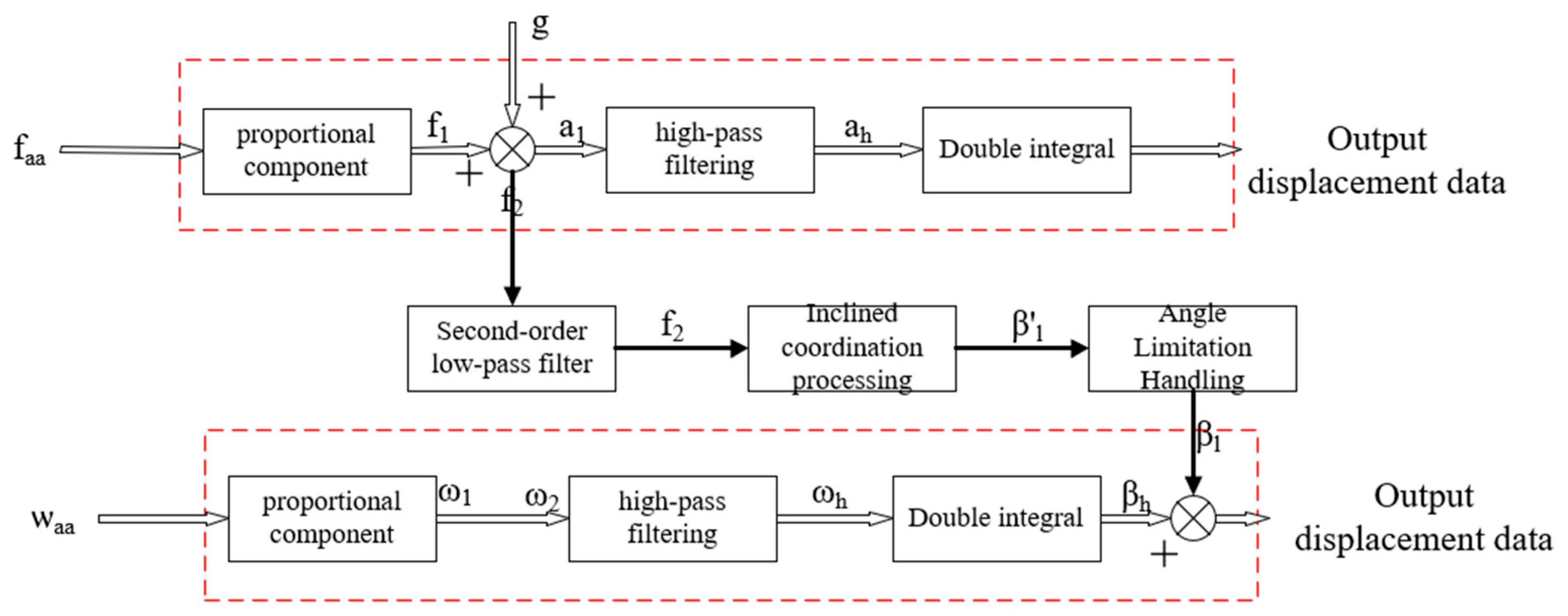
The actual range of motion of a ship is infinite. However, the spatial range of the parallel 6-DOF platform adopted in motion simulation is greatly restricted. The core objective of the washout algorithm in ship motion simulation is to fully simulate the motion characteristics of real ships within a limited spatial range. The core of the algorithm is to make full use of the acceleration in the form of specific force perceived by the human vestibular system, which cannot distinguish whether the perceived acceleration is generated by real ship motion or caused by gravity components. Therefore, the washout algorithm simulates the continuous acceleration motion of real ships by leveraging the acceleration components caused by gravity, which achieves a highly realistic simulation of the motion state of real ships within a limited motion space. The design principle of the classic washout algorithm is shown in
Figure 4.
The basic working principle of the washout filtering algorithm is to process the specific force signals perceived by the human vestibular system, which achieves a highly realistic simulation of the real ship’s movement within a limited motion space. The specific force signal is divided into high-frequency and low-frequency parts. Among them, the high-frequency signal represents the instantaneous acceleration. Firstly, to prevent the motion signal from causing the analog platform to exceed the limit, the proportional link is adopted to adjust to the input of the washing algorithm. Secondly, the high-frequency signal undergoes the coordinate transformation to obtain the specific force in the ship’s inertial coordinate system. This specific force is added to the gravity vector to obtain the corresponding acceleration . Then, the acceleration is processed through a high-frequency filter to obtain the angular velocity of the moving platform. In addition, the diagonal velocity is integrated twice to convert it into the displacement information of the platform. For the specific force of the low frequency part, the low frequency filter is used to filter out the high frequency signal, so as to obtain the low frequency specific force signal. In this step, the platform is tilted to create a component of gravity to simulate the continuous acceleration motion of the ship. To maintain the stability of the simulation process, the tilt coordination introduces an angle , which is adjusted to ensure that the platform operation does not exceed the working range. Finally, the tilting angle is limited to obtain the angle after the amplitude is limited. This process ensures that the comparative signal of the acceleration part is reasonably restored in the simulation platform, thereby achieving a realistic simulation of the ship’s motion.
Another part of the washout filtering algorithm is the processing of diagonal velocity signals to fully simulate the rotational motion of a real ship within a limited motion space. Firstly, the angular velocity signal perceived by the vestibular system is scaled through the proportional link to obtain the angular velocity . This step is to prevent the input signal from exceeding the maximum angular range of the analog platform’s movement, which ensures the stability of subsequent processing. Subsequently, the angular velocity transformation matrix is used for coordinate transformation, and the perceived angular velocity signal is converted from the platform coordinate system to the inertial coordinate system to obtain . After the coordinate transformation is completed, the signal is processed through a high-pass filter to filter out the low-frequency components and only retain the high-frequency angular velocity information to obtain . The purpose of this step is to extract the rapid rotation information related to the ship’s movement to ensure the high-frequency response of the simulation. After the integral processing of the high-frequency angular velocity signal, the angle transformation information of the platform was obtained. Next, the angle signal processed by low-pass filtering, and the angle signal processed by high-pass filtering are added to obtain the angles of the 6-DOF motion platform to roll, pitch, and yaw of the ship. This comprehensive processing procedure simulates the rotational motion of ships by effectively utilizing the angular velocity signals perceived by the human vestibular system, which provides a more realistic and accurate sense of motion for ship simulation driving.
3.2.1. Input Part
To avoid the problem that the motion platform of the ship driving simulation is restricted by the limited stroke of the six electric cylinders, preprocessing measures need to be taken to limit the input acceleration signal or angular velocity signal to ensure that it is within a reasonable range. This preprocessing uses the linear proportional scaling method, which adjusts the signal size by linear mapping to ensure that the output signal is within a predetermined amplitude range to prevent out-of-limit movement of the platform. The limited preconditioning provides a more controllable and stable motion environment for the simulator, which enables the ship driving simulator to reproduce the ship motion experience more realistically and safely in the simulated driving situation. The linear scaling expression used in this paper is as follows:
In the pre-processing of the wash-out algorithm, the input of the specific force signal undergoes two important steps, namely, clipping processing and coordinate transformation. Firstly, the main purpose of limiting the specific force signal is to avoid the out-of-limit movement of the platform caused by the excessive input acceleration signal or angular velocity signal. Then, the coordinate transformation of the specific force signal is to transform the signal from the hull coordinate system to the inertial coordinate system. The importance of this step is to ensure that the specific force signal matches the coordinate system of the simulator in the following processing. Through the matrix transformation, the specific force signal can be correctly processed in the inertial coordinate system, which provides an accurate input signal for the subsequent washing-out algorithm. The conversion formula is as follows:
where f
2 is the specific force in the inertial coordinate system, L
S is the transformation matrix of the specific force signal from the hull coordinate system to the inertial coordinate system, and f
1 is the specific force in the confined rear body coordinate system.
Similarly, the input angular velocity is first limited and then converted to the angular velocity in inertial coordinates. The transformation formula is expressed as follows:
where
represents the angular velocity in the inertial coordinate system;
represents the angular velocity in the restricted hull coordinate system; and
represents the transformation matrix for converting the angular velocity from the hull coordinate system to the inertial coordinate system.
3.2.2. High-Pass Acceleration Channel
The high-pass filter is responsible for filtering out the high-frequency part of the linear acceleration signal and plays a crucial role in simulating the instantaneous acceleration perception of a 6-DOF motion platform. The general equation of a high-pass filter is as follows:
The acceleration high-pass channel adopts a third-order high-pass filter, and its transfer function is as follows:
where
is the second-order damping ratio,
represents the second-order natural response frequency, and
is the natural response frequency of the first-order inertial part.
3.2.3. Inclined Coordinate Channel
The function of the inclined channel is to simulate the continuous acceleration sensation generated by low-frequency acceleration. However, due to the physical limitations of the motion platform, continuous translational simulation of the motion platform is not feasible. The inclined channel converts the input low-frequency acceleration into an inclined angle through a low-pass filter and generates a gravitational acceleration component parallel to the moving platform through the inclined angle, thereby simulating continuous acceleration. Since the tilt angle is only intended to simulate sustained acceleration, the inclined process cannot be perceived by the human body; thus, the inclined speed must be lower than the body’s feeling threshold. The inclined coordination channel adopts a second-order linear low-pass filter, and its transfer function is as follows:
where
is the low-frequency component of specific force on the
X-axis in the hull coordinate system (
),
is the
X-axis component of specific force in the hull coordinate system (
),
is the second-order low-pass filter cutoff frequency of the
X-axis direction (
), and
is the damping ratio of the second-order low-pass filter in the
X-axis direction, and it is dimensionless.
is the low-frequency component of specific force on the Y-axis in the hull coordinate system (), is the Y-axis component of specific force in the hull coordinate system (), is the second-order low-pass filter cutoff frequency of the Y-axis direction (), and is the damping ratio of the second-order low-pass filter in the Y-axis direction, and it is dimensionless.
3.2.4. High-Pass Angular Velocity Channel
The high-pass angular velocity channel washes out the angular displacement of the platform by performing high-pass filtering processing on three rotational motions: roll, pitch, and yaw. The specific process is to scale the angular velocity signal of the ship motion, filter out the low-frequency signal through a high-pass filter, and simulate the high-frequency motion of the ship in the sailing by reproducing the high-frequency angular velocity signal.
Therefore, the high-pass angular velocity channel adopts a second-order high-pass filter, and its transfer function is as follows:
In Equation (50), represents the second-order damping ratio coefficient; represents the second-order natural response frequency (rad/s).
4. Results
4.1. Experimental Methods and Environment
To verify the effectiveness of the virtual ship motion simulation and attitude simulation, a real ship is used for sea navigation to record navigation environment data and ship trajectory. Ship simulation experiments are conducted in a virtual environment, with conditions such as wind speed and direction set to match those of a real ship, and the virtual ship’s navigation trajectory is recorded. Conduct ship simulation driving experiments in a virtual environment. Set the same wind speed, wind direction, and other conditions as the actual ship’s navigation. Record the virtual ship’s navigation trajectory and compare it with the real ship’s navigation trajectory. Verify the effectiveness of the ship motion model. Meanwhile, the ship attitude data during the real ship movement process is compared with the virtual ship attitude data during the simulated driving process to verify the simulation effect of the virtual ship attitude.
To verify the effectiveness of the ship driver’s motion simulation model, the correlation index between the real ship attitude data and the attitude data of the six-degree-of-freedom platform is first analyzed to illustrate the acceleration simulation effect. At the same time, 20 crew members with more than 3 years of maritime work experience are hired to conduct a simulated ship driving experience evaluation. The closest to the real ship in terms of physical feel is 5 points, decreasing sequentially. The closest to the real ship in terms of physical feel is 0 points.
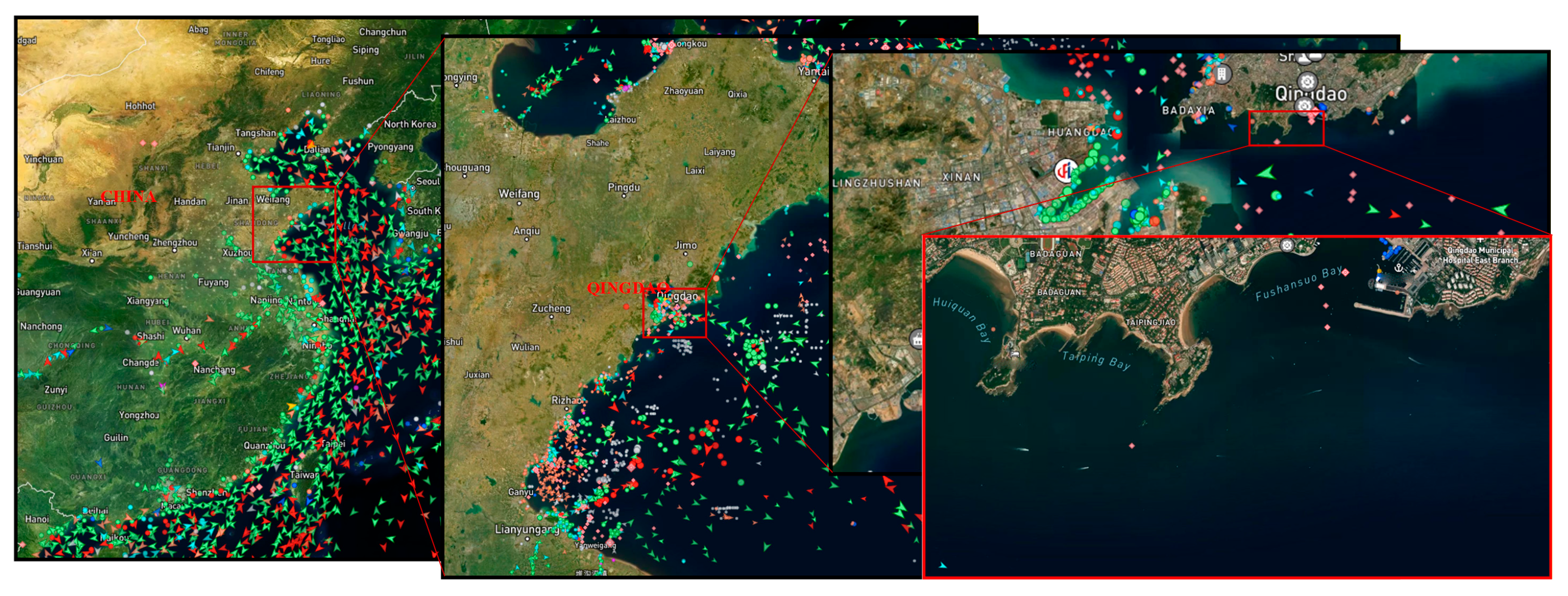
The real ship experiment is conducted in the relevant waters of Yinhai Wharf in Shinan District, Qingdao. The location of the research area is shown in
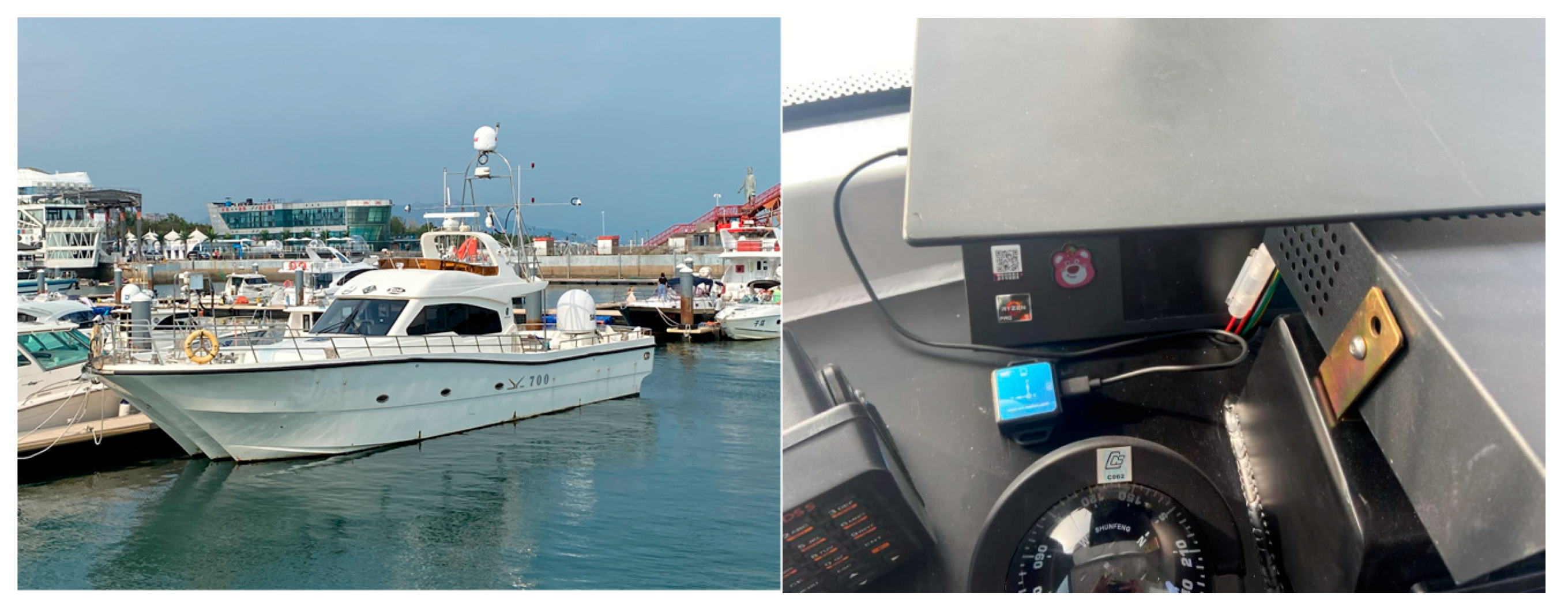
Figure 5. The ship is equipped with a six-freedom sensing device, model “Witt WT901SDCL” (Shenzhen Weite Intelligent Technology Co., Ltd., Shenzhen, China). The high-precision positioning equipment selected is the “Qianxun Zhicun FindCM 5-star 16-frequency” model (Qianxun Location Network Co., Ltd., Beijing, China). The six-degree-of-freedom platform adopts a small six-axis attitude simulation platform customized and developed by Nanjing Quankong Technology. The comparative data sources are provided by the aforementioned equipment for ship maneuverability experiments and motion reproduction experiments. The experimental vessel is a small to medium-sized yacht made of aluminum alloy. Its main parameters are shown in
Table 3. The photos of the navigation experiment site and the data acquisition device are shown in
Figure 6. Some navigation data of the experimental ship are shown in
Table 4.
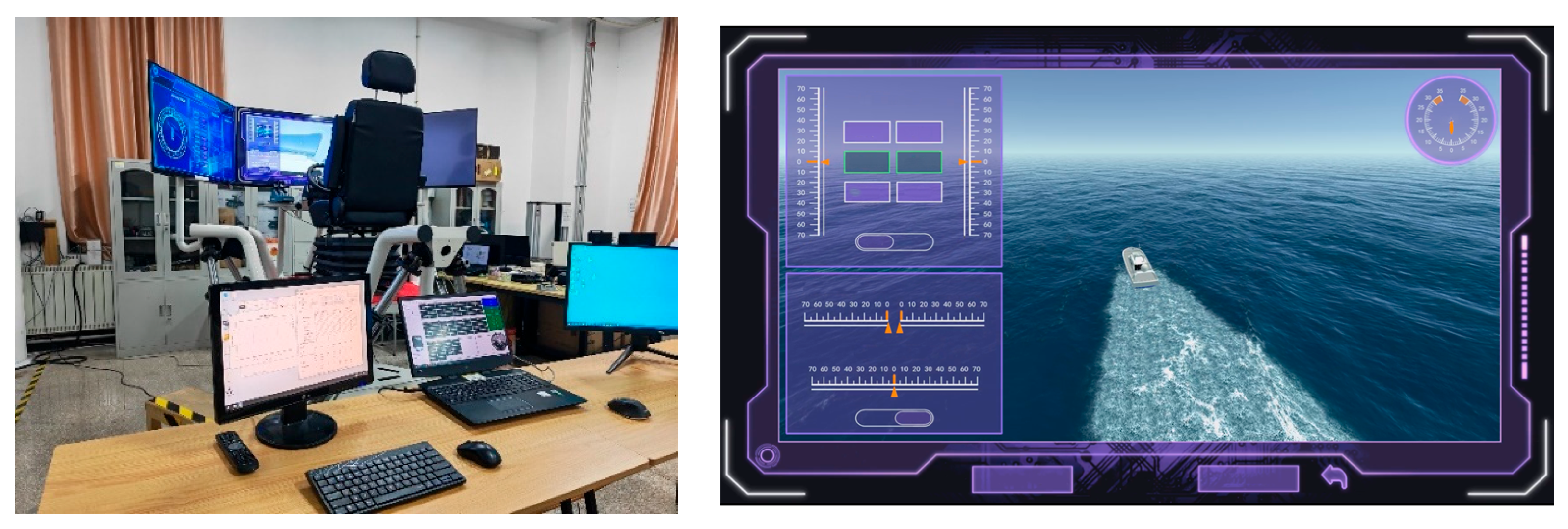
The six-degree-of-freedom motion platform is a parallel mechanism, which consists of a moving platform, a stationary platform, and six identical moving cylinders. The moving cylinder is connected to the moving and stationary platforms by Hooke hinges. The moving platform is connected to the top of the moving cylinder via the Hooke hinge. The stationary platform is connected to the bottom of the moving cylinder. The motion cylinder is electrically driven. The motor controls the movement, extension, and rotation of the motion cylinder, thereby controlling the movement of the moving platform. The parallel six-degree-of-freedom motion platform and virtual experimental scenario used in this research are shown in
Figure 7.
The virtual driving software used in this paper is developed with the personal license version of the unity3d (Version 2019.4.3f1) virtual engine, programmed with the C# language, and uses the 3ds Max (Version 2022) student version to draw the three-dimensional model in the virtual scene. The driving simulation software and the six-degree-of-freedom platform carry out data transmission in the local LAN. The basic transmission mode is UDP network transmission. The six-degree-of-freedom platform driver is written in C. ABB industrial control suite is used to drive the six-degree-of-freedom platform electric cylinder to realize the six-degree-of-freedom angular and acceleration movement of the platform.
The transformation matrix from the angular velocity in the hull coordinate system to the Euler angle rate of change in the inertial coordinate system is
.
is function, is function, t is function, is the current roll angle of the six-degree-of-freedom platform. is the current pitch angle of the six-degree-of-freedom platform.
4.2. Experimental Results Analysis
The data analyzed in this paper mainly include ship trajectory data, six-degree-of-freedom angle data, six-degree-of-freedom angular acceleration data, etc. After statistics, the amount of data collected is not very large, so the data analysis is mainly carried out using MATLAB (Version R2025a 25.1.0.2943329), Python (Version 3.12), and other general tools and programming languages.
4.2.1. Navigation Trajectory Experiment
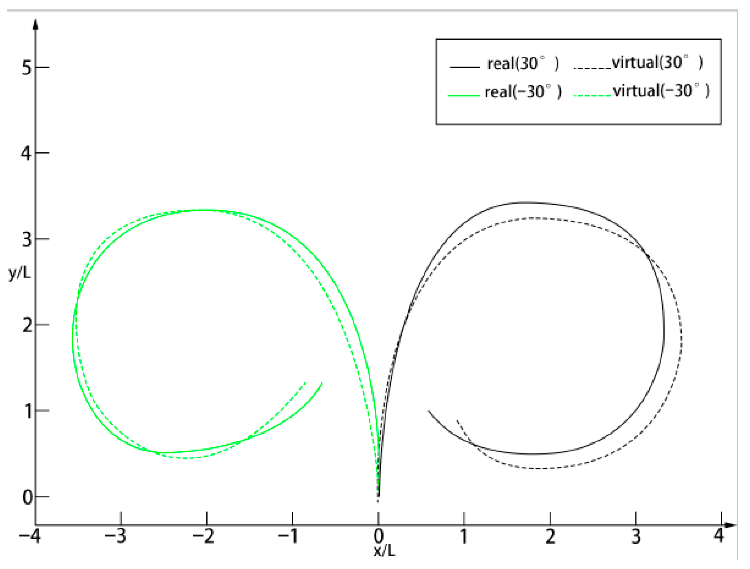
To verify the accuracy of the ship’s trajectory, a ship turning experiment is conducted under low sea state conditions with light winds and waves. The real ship’s trajectory is compared with the virtual ship’s trajectory. Based on the established ship motion model, the fourth-order Runge–Kutta method is used to solve the model with a step size of 0.1 s. Simulation data is obtained through simulation calculation. The experimental data from sea trials are compared with the simulated data. The turning circle elements, such as steady turning diameter, maximum heel angle, and stable heel angle, are analyzed.
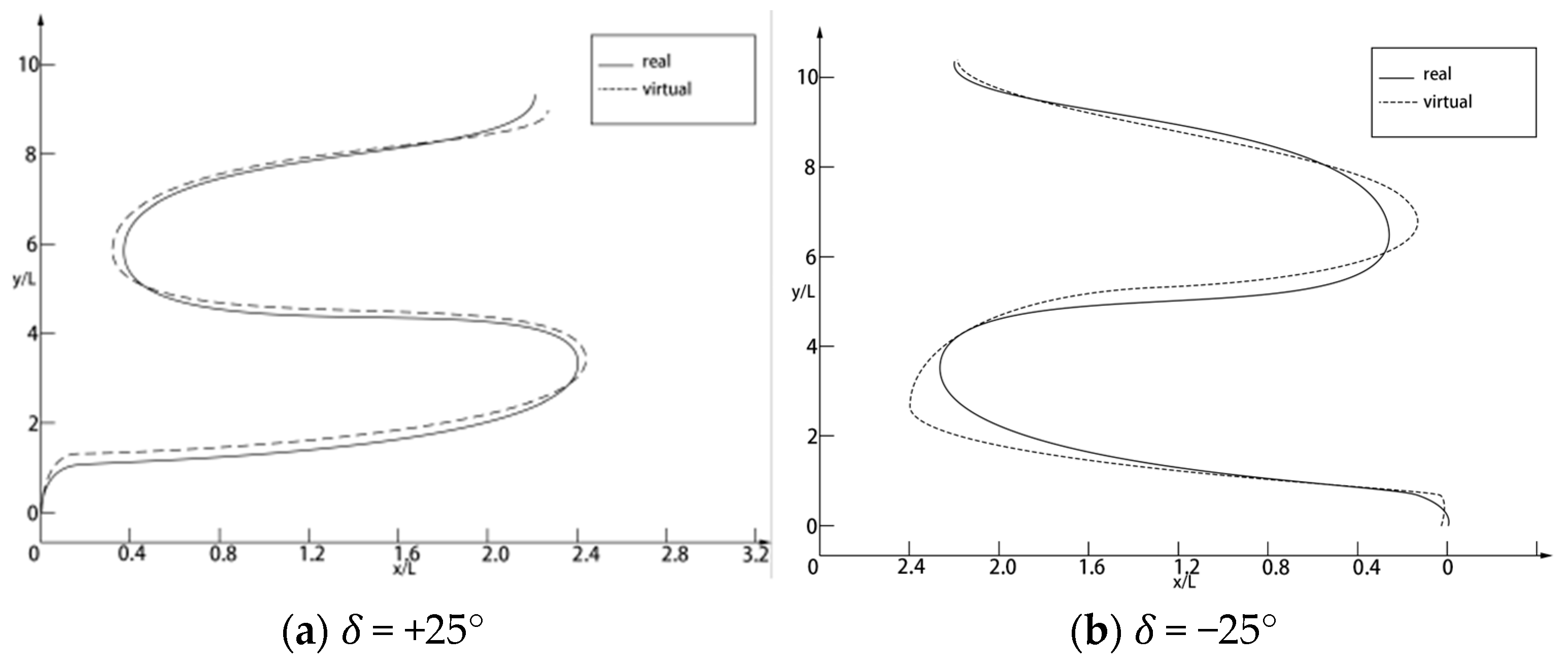
The simulated ship speed is eight knots. The rudder angle is ±30° (left rudder is −, right rudder is +). The approximate curve of the ship’s motion is recorded. The experimental process curve is shown in
Figure 8. The Z-shaped simulation and test results using ±25°/25° rudder angles are shown in
Figure 9. In addition, a comparison of turning indices, including forward distance and tactical diameter, is shown in
Table 5.
According to
Figure 8, the rotational trajectory at a rudder angle of ±30° shows that after entering the steady rotation circle, the rotational trajectories of the two are consistent and basically match. According to
Figure 9, the Z-shaped test trajectory shows a good fit between the two turns and is stable, meeting the required ship motion capability.
In
Table 5, the relative errors in the forward distance for left-hand drive and right-hand drive are 11.3% and 9.7%, respectively. The tactical diameter errors for the left and right rudders are 6.2% and 8.3%, respectively. The two exceedance angles are compared in
Table 6. Due to the interference of the marine environment on ship navigation, it has regularity in a certain period. Therefore, in the process of ship motion simulation, the error of the motion trajectory compared with the real ship trajectory is less than 15%, which shows that the ship motion model is effective. The correlation errors for +25° are 18.6% and 20.1%, respectively. The errors for −25° are 23.4% and 16.9%, respectively. The motion trajectory and data show that the experimental results and simulation results of the model are in good agreement. The constructed ship motion model is proven to have high accuracy in the description of ship motion in a planar environment and can be applied to ship motion simulation in a virtual scene.
4.2.2. Flight Attitude Simulation Experiment
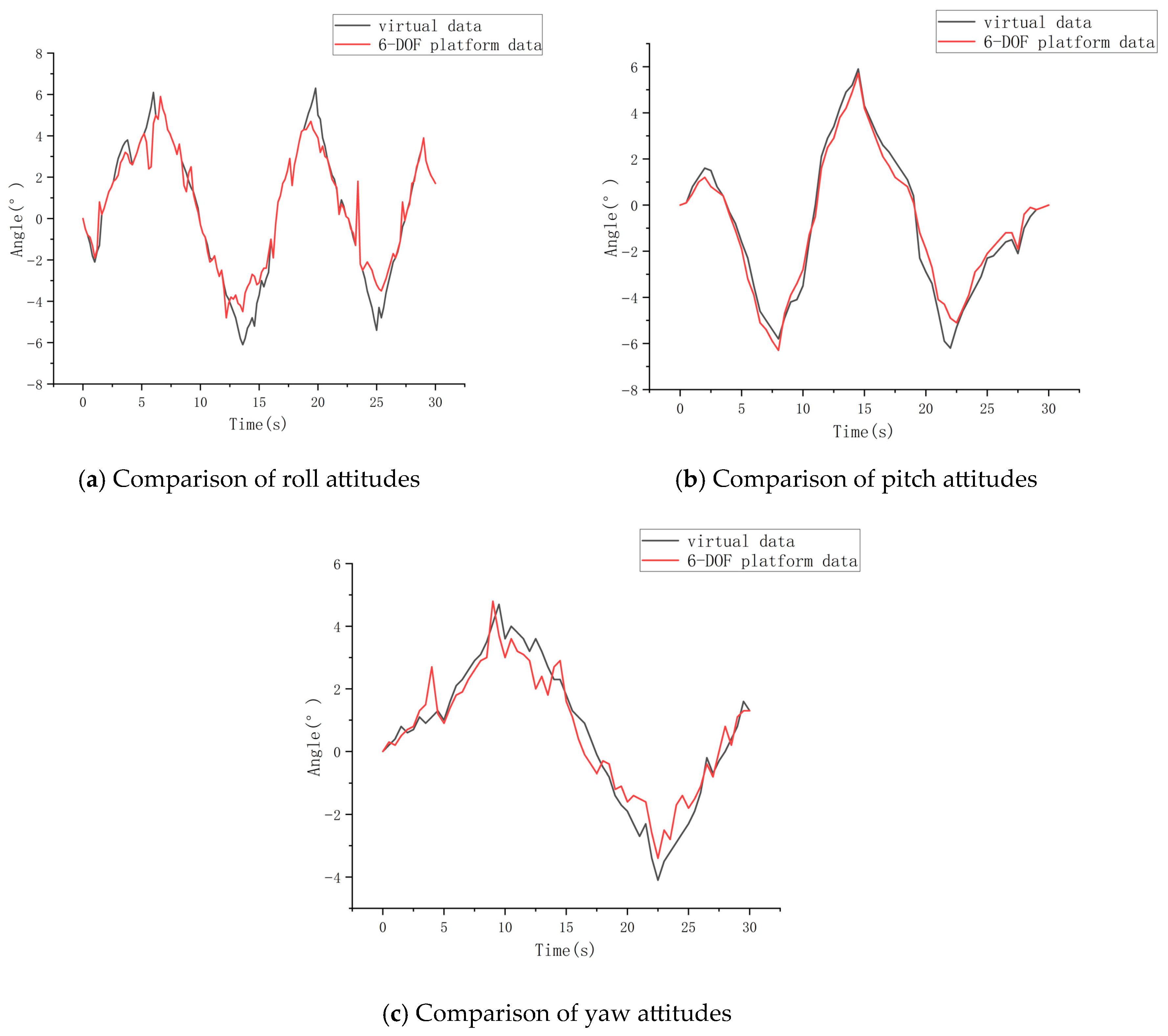
In a 30 s virtual motion scene, the images of the virtual ship’s motion attitude and the motion fit of the six-degree-of-freedom motion platform are shown in
Figure 10. Since heave, sway, and pitch are simple displacement variables in ship attitude simulation during navigation. Their measurement methods are relatively simple. To simplify the experimental process, only the ship’s roll, pitch, and bow degrees of freedom were collected in this experiment to verify the effectiveness of the ship attitude simulation.
Figure 10a shows roll,
Figure 10b shows pitch, and
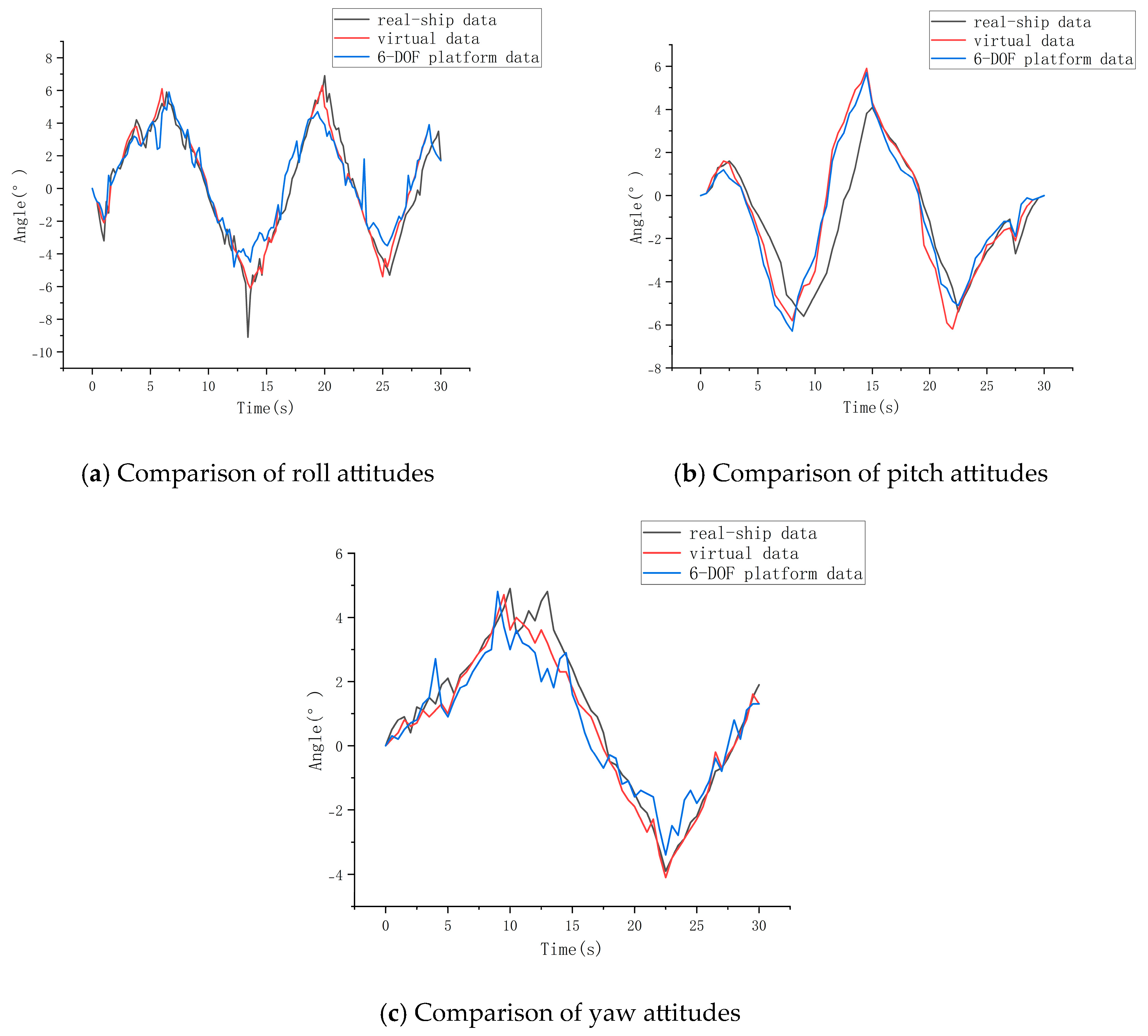
Figure 10c shows bow roll. Overall, the motion curves in roll, pitch, and yaw have similar shapes. The overall trend of ship motion is consistent. The maximum relative error rates for the three motion states are 36.5%, 43.1%, and 34.6%, respectively. Higher error values usually occur when the motion posture changes drastically because the motion platform has a limited motion space and will produce limited motion for drastic movements. The error rate of the bow roll is lower than that of the roll and pitch. The high-frequency motion of bow rolling is relatively small during ship operation. The angle of motion is smaller compared to roll and pitch; the simulation effect of the ship attitude during stable motion is better.
4.2.3. Driver’s Sensory Experience Reproduction Experiment
- (1)
Correlation analysis of posture feature data
To verify whether the virtual driving experience closely resembles the real-world experience under low sea conditions with light winds and waves, the correlation of attitude data is used as an evaluation index. Simultaneously, data from the actual ship, the virtual ship’s output, and the six-degree-of-freedom platform’s execution (i.e., the virtual pilot’s experience data) are compared. The correlation between real ship data and execution data of the six-degree-of-freedom platform is used as an evaluation index for tactile reproduction. The correlation between real ship data and virtual ship data is used as an evaluation index for the simulation effect of the virtual ship, which also shows that the sea environment simulated by the virtual ship is similar to that of a real ship.
Analysis of real ship data, virtual ship data, and motion data from a six-degree-of-freedom motion platform is shown in
Figure 11. The roll deflection angle under simulated sway acceleration is shown in
Figure 11a. The pitch deflection angle under simulated sway acceleration is shown in
Figure 11b. The bow roll angle is shown in
Figure 11c. As can be seen from the figure above, under the same wind and wave loads, the virtual ship’s attitude is almost identical to that of the real ship. The motion trends are the same, which indicates that the virtual ship has a good simulation effect on the motion attitude of the real ship. The correlation coefficients of the six-degree-of-freedom motion platform with the real ship’s motion attitude are 89.3%, 81.2%, and 83.6%, respectively. Similarly, although the limiting action of the motion platform on high-frequency motion signals results in a slightly lower reproduction rate of violent motion compared to low-frequency motion, the trend of ship motion can still be reflected. The sensory experiences of humans on real ships and six-degree-of-freedom platforms can be reflected in the correlation of data. It is shown in the data that the correlation coefficient between the six-degree-of-freedom platform and the real ship is the lowest at 81.2%. The attitude data change trend and amplitude change characteristics of the six-degree-of-freedom platform are consistent with the real ship data. Therefore, the platform can reproduce the ship’s driver’s sense of motion in low sea states to a certain extent.
- (2)
Simulated driving experience rating
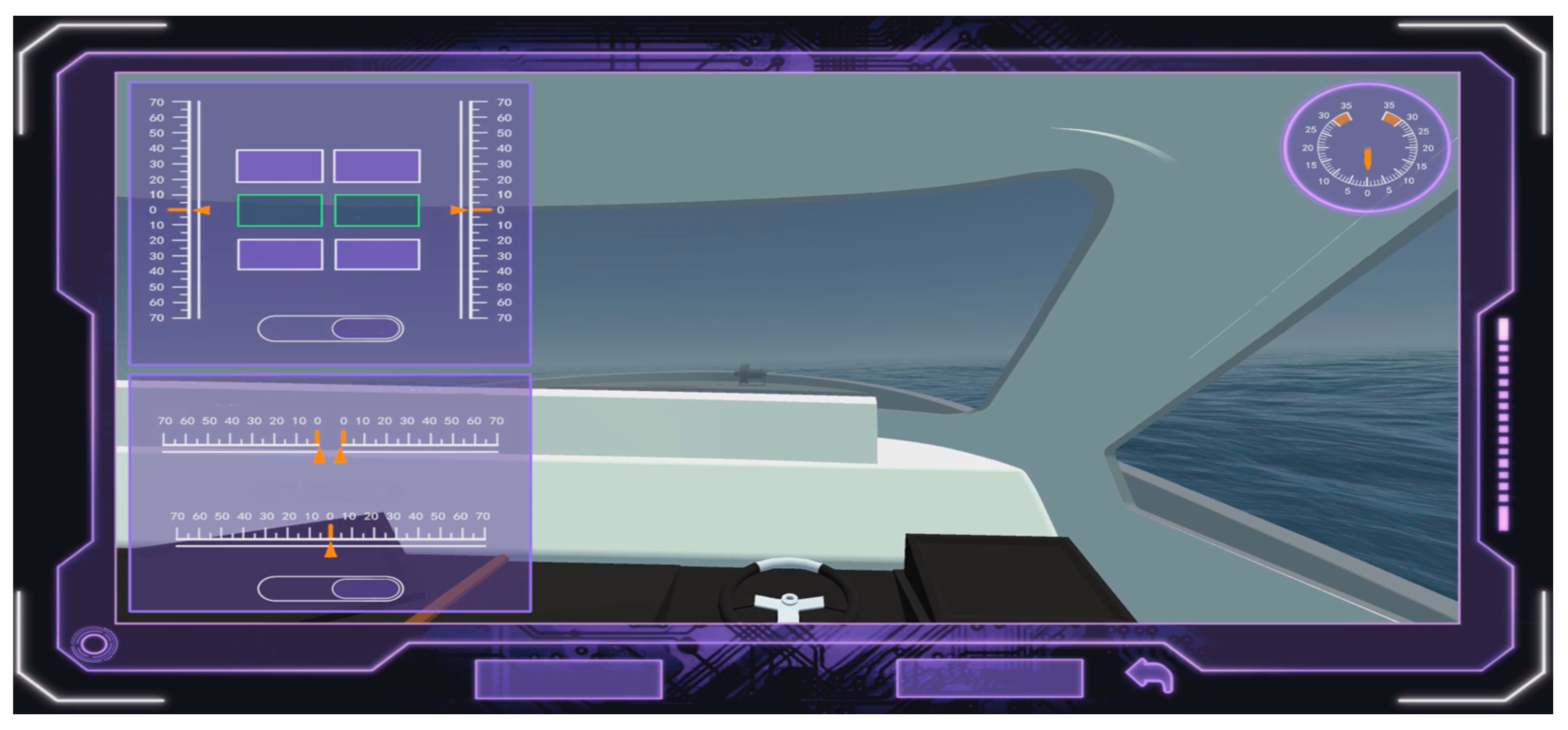
A fixed virtual navigation route is used in the simulated driving experiment. The same low sea state setting is used. The weather conditions and visibility conditions are set to clear. The virtual environment scene is shown in
Figure 12.
Each virtual driving experiment lasts 15 min, starting directly from the sea, eliminating the docking and undocking processes. The first 5 min of the experiment are the equipment adaptation period. The requirement is to perform three maneuvers consecutively within five minutes: straightening the vehicle, turning left at 25 degrees, and turning right at 25 degrees. During this period, participants familiarize themselves with the driving simulator and adapt to the visual experience, minimizing the impact of visual factors on their sensory evaluation.
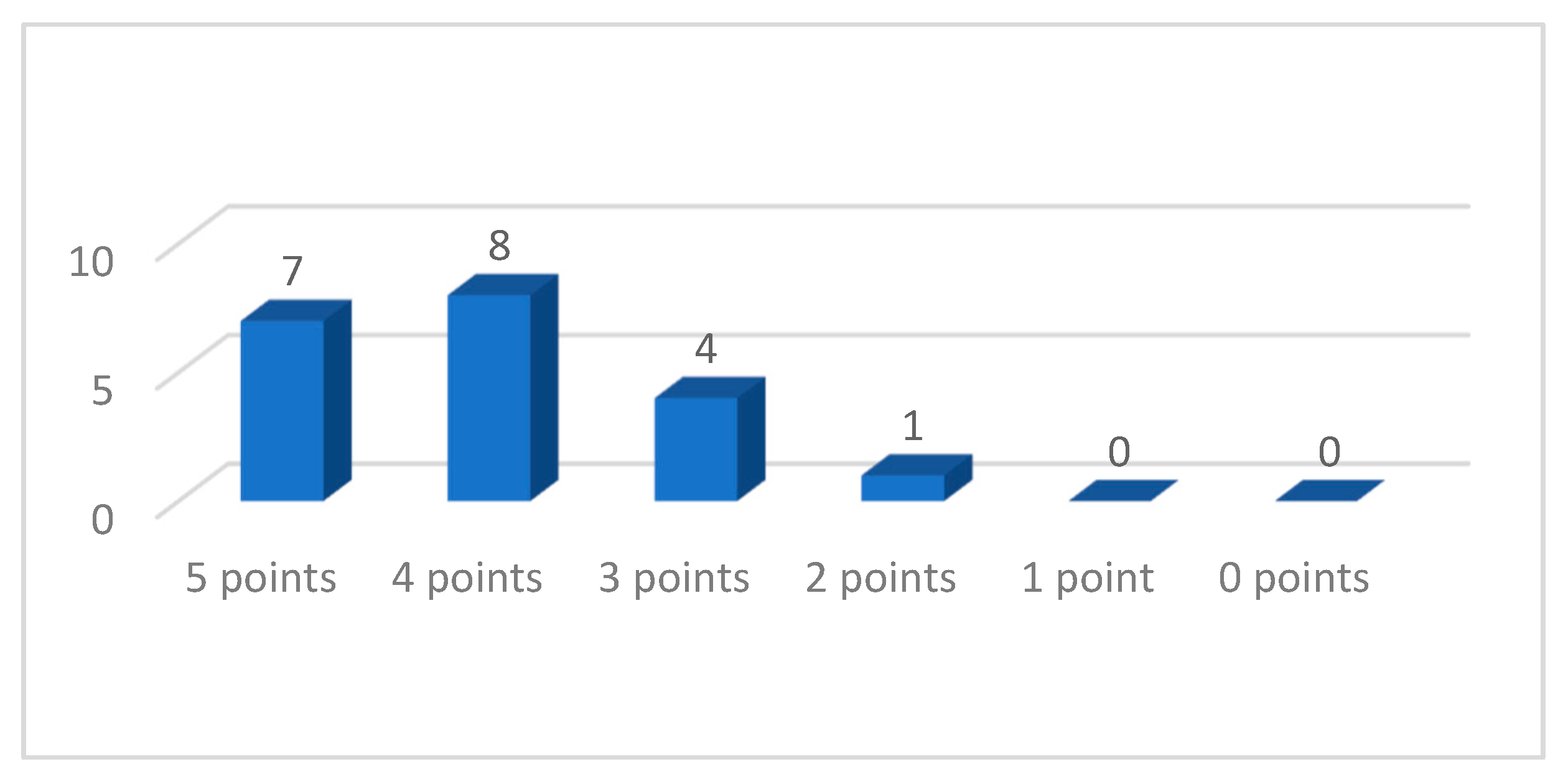
Twenty captains and crew members with more than three years of experience working on yachts are recruited to participate in the experiment. They are all male and between the ages of 24 and 32. The results of their driving experience are shown in
Figure 13.
It is stipulated in the experiment that a score of 5 is awarded for the closest physical experience to the real ship, decreasing sequentially, with a score of 0 for a completely different experience. A score of 4 or higher is considered a good representation of the physical experience. The driving experience scoring results show that 15 people, accounting for 75% of the total, gave a score of 4 or higher, indicating a good representation of the physical experience.
After the real ship data acquisition experiment on the sea, the heave often has little effect on the human sensory during the navigation of ships over 100 m, and the roll, pitch, and heave are relatively easy to directly control the angle and angular acceleration in the six-degree-of-freedom platform to realize the reproduction of the driver’s sensory perception. On the basis of this study, subsequent researchers can directly add roll, pitch, and heave commands to the washout algorithm and use the additional reproduction commands to realize the reproduction of the ship driver’s body feeling in high sea conditions.




 ,
,