

Article

A Modified Constrained Groove Pressing Process (MCGP) for Enhanced Strength and Microstructural Refinement of Deoxidized High-Phosphorus (DHP) Copper Sheets: Potential Implications for Marine Component Reliability
by
Mohsen Forouzanmehr
1,
Mohammad Reza Dashtbayazi
1,
Kazem Reza Kashyzadeh
2 and
Mahmoud Chizari
3,*
1
Department of Mechanical Engineering, Shahid Bahonar University of Kerman, Kerman 7618868366, Iran
2
Department of Transport Equipment and Technology, Academy of Engineering, Peoples’ Friendship University of Russia (RUDN University), 6 Miklukho-Maklaya Street, Moscow 117198, Russia
3
School of Physics Engineering and Computer Science, University of Hertfordshire, Hatfield AL10 9AB, UK
*
Author to whom correspondence should be addressed.
J. Mar. Sci. Eng. 2026, 14(16), 1455; https://doi.org/10.3390/jmse14161455
Submission received: 18 June 2026 / Revised: 21 July 2026 / Accepted: 4 August 2026 / Published: 7 August 2026
(This article belongs to the Special Issue Marine Equipment Intelligent Fault Diagnosis)

Abstract

Deoxidized high-phosphorus (DHP) copper is widely used in marine heat-exchangers and seawater piping, where long-term structural reliability demands both high strength and a deformation-tolerant microstructure to resist damage initiation. Constrained groove pressing (CGP) is a scalable severe plastic deformation route for metallic sheets; however, the sharp trapezoidal junctions of the conventional die impose parasitic bending strains that produce sinusoidal in-plane hardness variations and anisotropic properties. This study introduces a modified CGP (MCGP) process in which the sharp crest and valley of each 45° tooth are replaced by tangent circular arcs (R1 = 1.6 mm at the crest, R2 = 4.8 mm at the valley), removing geometric discontinuities while exactly preserving the groove angle, pitch, and die envelope for drop-in compatibility with existing equipment. DHP copper sheets processed by conventional CGP and MCGP were systematically compared using optical microscopy, SEM, XRD, microhardness, tensile testing, and finite-element analysis. MCGP delivered exceptional mechanical performance: yield strength of 281.19 MPa, ultimate tensile strength of 451.94 MPa (96.4% above the as-received state and 23.8% above conventional CGP), mean hardness of 131.38 HV, and the finest apparent (instrument-uncalibrated) coherent diffraction-domain size of 22.75 nm. Finite-element modelling revealed a lower peak equivalent plastic strain with a more continuously distributed through-thickness deformation path, despite an unchanged nominal grooving strain (≈0.56). Notably, while the modified die redistributes deformation rather than amplifying the nominal strain, the measured through-thickness hardness inhomogeneity factor increased from 7.14% to 21.97% due to strain concentration in the mid-thickness region, indicating that full homogenisation requires further arc-radius optimisation. Nevertheless, the substantial gains in strength and microstructural refinement demonstrate that MCGP offers a promising processing route for producing DHP copper components with enhanced strength and refined microstructures, which may contribute to improved damage tolerance. However, it is acknowledged that direct tests on seawater corrosion, corrosion fatigue, and thermal cycling were not performed in this study; the implications for marine service life are inferred from the established literature on the benefits of grain refinement for corrosion and fatigue resistance. Future work incorporating marine environmental performance tests is recommended to validate these implications.

1. Introduction

The structural reliability of marine equipment depends critically on the damage tolerance and long-term performance of its metallic components, particularly those exposed to cyclic loading, corrosive seawater, and thermal cycling in heat-exchangers and piping systems. Severe plastic deformation (SPD) comprises a family of metal-forming techniques in which large plastic strains are imposed on a workpiece under highly constrained conditions to generate an ultrafine-grained (UFG) microstructure without any macroscopic change in specimen dimensions [1,2]. The accompanying grain refinement to the sub-micron, and in some cases nanometric, scale markedly elevates strength, hardness, and fatigue resistance through the classical Hall–Petch relationship; concurrently, the increased grain-boundary density impedes dislocation slip and suppresses the formation of persistent slip bands that would otherwise nucleate fatigue cracks [3,4].
Among the SPD techniques established for bulk materials, including equal-channel angular pressing, high-pressure torsion, and accumulative roll bonding, CGP has emerged as the most industrially viable route for metallic sheets, owing to its preservation of sheet dimensions, scalability to large areas, and compatibility with standard hydraulic presses [5,6,7]. Originally introduced by Shin et al. [5], CGP subjects a metallic sheet to cyclic shear deformation under plane-strain conditions through alternating pressing between asymmetrically grooved dies (groove angle θ = 45°) and flat dies, with each complete cycle imparting an effective plastic strain of approximately 1.16 distributed across successive shear and straightening stages. A fundamental limitation of the conventional process, however, is the strain inhomogeneity intrinsic to its sharp trapezoidal groove profile: the geometric discontinuity at the groove junctions superimposes a localized bending strain on the intended shear deformation, producing the characteristic sinusoidal hardness distribution observed across the transverse direction of processed sheets and the attendant anisotropy in mechanical response [8,9].
Considerable effort has therefore been directed at suppressing this inhomogeneity. Intermediate and post-process annealing can partially relax the non-uniform strain field and reduce hardness scatter, but at elevated temperatures it promotes abnormal grain growth that erodes the strength gained during deformation [10]. Process-level variants, including rubber-pad CGP, cross-CGP with rotated strain paths, and assorted die-geometry modifications, have each improved deformation uniformity to varying degrees [11]. Curved-groove concepts such as constrained constant-radius pressing and corrugated uniform-pressing dies have shown that replacing the sharp corners with continuous radii directly suppresses the parasitic bending strain, yielding more uniform dislocation structures and reduced property anisotropy [12]. A particularly relevant line of work has tailored the die geometry specifically for copper sheets: constrained studded pressing (CSP) replaces the continuous groove with two rows of orthogonal studs, raising the per-pass effective strain while removing the need to rotate the specimen between steps [13]; a modified CSP variant with asymmetric semicircular studs further increases the attainable groove depth and strain [14]; and systematic studies of stud angle [15] and of groove, studded, and modified-studded geometries [16] have together shown that such designs refine the microstructure and raise the ultimate tensile strength of copper while lowering residual stress. Collectively, these investigations establish that it is the geometric discontinuity of the conventional trapezoidal die, not the shear mechanism itself, that is the principal source of inhomogeneity, motivating a die geometry that retains the proven shear kinematics of CGP while eliminating its sharp transitions.
Despite these advances, the existing curved and stud-based variants achieve homogeneity by departing substantially from the original CGP tooling, altering the groove angle, pitch, or overall die envelope, so that they require purpose-built dies rather than functioning as a drop-in replacement for installed CGP equipment. Moreover, their assessment has been confined almost exclusively to high-purity copper and brass under laboratory conditions. The specific gap addressed by the present study is twofold: (i) the development of a die geometry modification that removes the parasitic bending strain while exactly preserving the 45° groove angle, pitch, and die envelope of conventional CGP (enabling drop-in compatibility with existing equipment), and (ii) the evaluation of this modified process on DHP copper intended for marine service, where the combination of corrosion resistance and mechanical reliability is critical. To date, no study has reported such a modification with drop-in compatibility, nor has such a process been evaluated on DHP copper for marine applications.
Deoxidized high-phosphorus copper, corresponding to UNS C12200, is widely used in marine heat-exchanger and piping components owing to its excellent corrosion resistance in chloride-rich seawater and its immunity to hydrogen embrittlement during thermal processing [17]. Because these components operate under cyclic thermal and mechanical loading, their durability depends not only on strength but also on resistance to corrosion and corrosion fatigue. Comprehensive surveys show that the grain refinement introduced by SPD, while substantially raising strength, does not compromise, and in copper can even enhance, corrosion and corrosion-fatigue performance [18,19]. From the perspective of marine equipment reliability, the homogeneity of the deformed microstructure is of particular importance: strain localisation and property anisotropy create preferential sites for corrosion and fatigue crack initiation, which are among the most common failure modes in seawater-exposed components. By suppressing these heterogeneities, improved SPD routes contribute to fault prevention by delaying the initiation of damage that would otherwise lead to premature component failure. Beyond grain refinement, the reliability of metallic components in service is ultimately governed by their resistance to fatigue crack initiation and propagation, making failure and fracture analysis an essential complement to microstructural characterisation when assessing process-induced property improvements. Recent advances in machine learning and data-driven approaches have demonstrated the potential for accurate fatigue life prediction and reliability assessment of structural components, underscoring the importance of understanding the relationship between microstructure, mechanical properties, and long-term performance. Severe plastic deformation and surface-treatment routes have repeatedly been shown to retard fatigue crack growth and extend service life by refining the microstructure and introducing beneficial compressive residual stresses, highlighting the practical relevance of the homogeneous, defect-tolerant microstructures targeted in the present work [20,21,22].
This materials-focused approach aligns with the marine equipment reliability theme of this Special Issue by addressing the intrinsic material condition that underpins component performance. By improving microstructural homogeneity and suppressing strain-localisation sites, the proposed MCGP process contributes to damage tolerance and extended service life, which are essential for the reliable operation of marine systems. The present study introduces a MCGP process in which the sharp crest and valley of each 45° trapezoidal die tooth are replaced by tangent circular arcs (R1 = 1.6 mm at the crest and R2 = 4.8 mm at the valley), thereby eliminating the geometric discontinuities while preserving the 45° groove angle, pitch, and overall die envelope so that the modified dies remain compatible with existing CGP equipment. Commercially pure DHP copper was selected as the model material owing to its widespread use in marine applications, where microstructural homogeneity and mechanical reliability under service conditions are critical. The evolution of the microstructure and mechanical properties of DHP copper sheets processed by the proposed MCGP route is systematically investigated using optical microscopy, scanning electron microscopy, X-ray diffraction, microhardness measurements, tensile testing, and finite-element simulation. The results are compared against conventional CGP to assess the improvements in deformation uniformity, grain refinement, and mechanical performance.

2. Materials and Methodology

2.1. Material

Commercially pure DHP copper was selected as the starting material to investigate the effects of conventional CGP and the proposed MCGP on the microstructural and mechanical characteristics of processed sheets. DHP copper (UNS C12200), supplied by CSP Co., Kerman, Iran, was chosen owing to its excellent corrosion resistance and widespread use in marine heat-exchanger and piping components. The material corresponds to the Cu-DHP grade, defined by a minimum copper content of 99.9 wt.% and a residual phosphorus content of 0.015–0.040 wt.%, where phosphorus acts as a deoxidizer that suppresses oxide formation and provides immunity to hydrogen embrittlement during thermal processing [17]. The as-received material was cut into sheet specimens of dimensions 75 × 58 × 3 mm3 for the pressing operations.
To obtain a homogeneous, equiaxed, and more formable initial grain structure, and to reduce residual stresses, each sheet was annealed at 600 °C for 1 h, followed by slow furnace cooling and subsequent cooling in still air, producing a fully recrystallized, equiaxed grain structure [22].

2.2. Conventional CGP and MCGP Processes

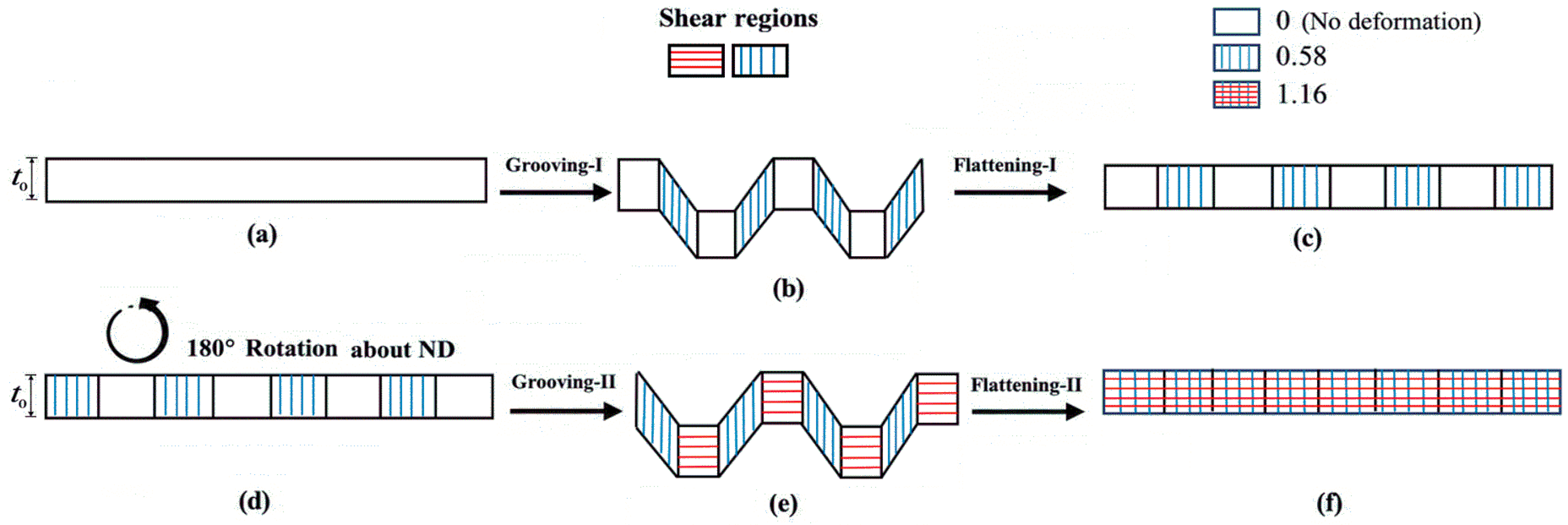
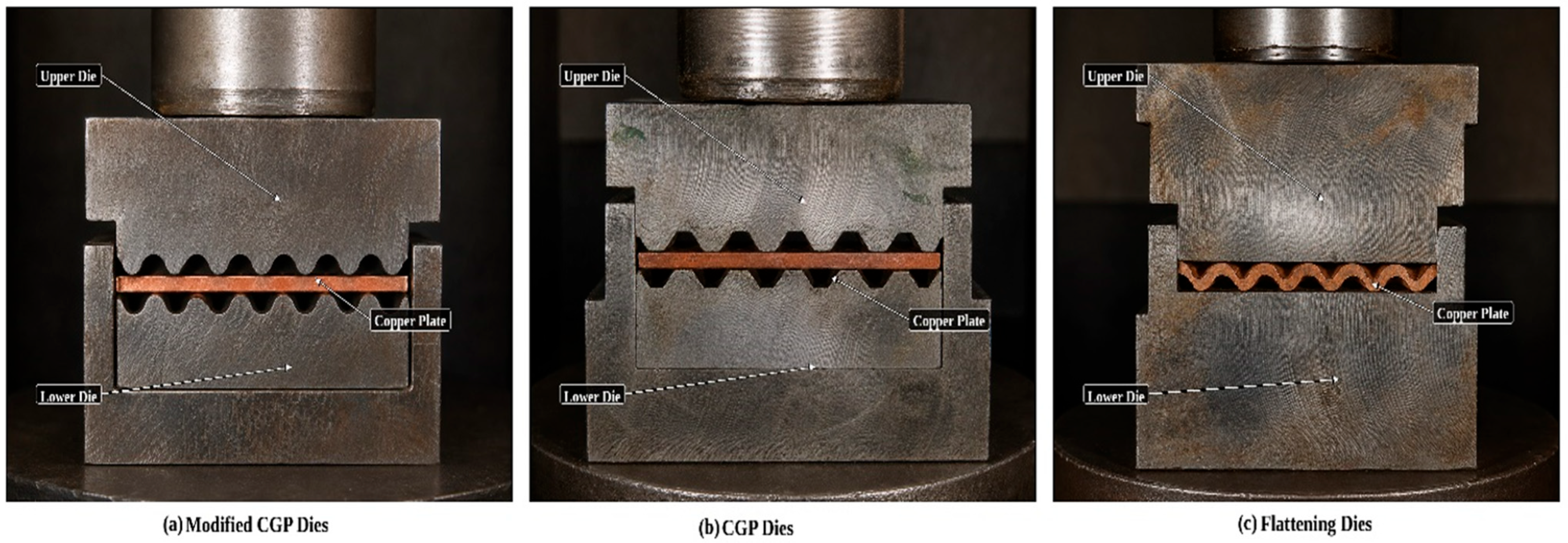
Both the conventional CGP dies (upper grooved, lower grooved, and flat) and the proposed MCGP dies were manufactured from CK60 tool steel (DIN 1.0601; Iran Alloy Steel Co. (IASCO), Yazd, Iran), and all pressing operations were carried out on an Instron hydraulic press with a capacity of 1000 kN (Instron, High Wycombe, UK). In the conventional CGP method, the sheet is subjected to repetitive orthogonal shear deformation under plane-strain conditions by pressing alternately with asymmetrically grooved (45°) and flat dies, as illustrated schematically in Figure 1. In the first pressing, the initial sheet is placed between the grooved dies, the sheet thickness (t) being equal to the gap between the upper and lower grooving dies; the inclined regions of the sheet then undergo pure shear under plane strain (Figure 1b), while the flat regions remain undeformed. Grease was used on the sheets to ensure adequate lubrication during pressing. In the second pressing, the grooved sheet is flattened with flat dies so that the previously deformed regions experience shear in the reverse direction while the undeformed regions remain unchanged (Figure 1c); the effective strain accumulated in the deformed regions after these two steps is approximately 0.58. The specimen is then rotated by 180° about the axis normal to the sheet plane (Figure 1d) so that, in the third and fourth pressings, the previously undeformed regions are grooved and then flattened in turn (Figure 1e). This sequential pressing with grooved and flat dies produces a theoretically uniform effective strain of 1.16 across the sheet after one complete pass (Figure 1f) [12].
In the proposed MCGP process, the sharp crest and valley junctions of each 45° trapezoidal tooth are replaced by two circular arcs inscribed tangentially to the flat and inclined die surfaces, a smaller arc of radius R1 at the crest and a larger arc of radius R2 at the valley. By replacing the sharp junctions with tangent arcs, the geometric discontinuity at each crest and valley is removed together with the localized bending strain it superimposes on the intended shear, while the 45° groove angle, the groove pitch, and the overall die envelope are preserved unchanged, so that the modified dies remain dimensionally interchangeable with existing CGP tooling.
Crucially, the two arc radii are not free design parameters; both are fixed uniquely by the conventional 45° tooth geometry. The dual-radius profile is generated from two mutually tangent circular arcs: the crest arc, of small radius R1, defines the high-curvature region of the profile, while the valley arc, of larger radius R2, governs the low-curvature transition region. The curvature of each segment is defined as
κ = 1 R
where R is the local radius of curvature and κ the corresponding curvature. The crest radius R1 was determined from the circumcircle passing through three characteristic points of the groove profile. From analytical geometry, the circumradius of the triangle defined by these three points is
R 1 = a b c 4 A
where a, b and c are the side lengths of the triangle and A is its enclosed area. The side lengths are obtained from the coordinates of the three points as follows:
a   =   x 2 x 1 2   +   y 2 y 1 2
b = x 3 x 2 2 + y 3 y 2 2
c = x 3 x 1 2 + y 3 y 1 2
and the enclosed area is given by
A = 1 2 x 1 y 2 y 3 + x 2 y 3 y 1 + x 3 y 1 y 2
In a single 2-D coordinate system (x along the groove pitch, y along the groove depth, in mm), the crest arc passes through the two junction points (6, −3) and (9, −3) and the intermediate arc point (7.5, −4.081). Substituting these coordinates into Equation (2) (a = 3.000 mm, b = c = 1.849 mm, A = 1.622 mm2), for the 45° groove profile with groove depth h = 3 mm and groove width 3 mm, yields R1 ≈ 1.6 mm (centre at (7.5, −2.5)), corresponding to the high-curvature crest deformation zone [3,5].
To ensure a smooth strain-transfer path, the valley arc was then introduced under the condition of tangency between the two circles. For two externally tangent circles, the distance between their centres equals the sum of their radii:
d   =   R 1   +   R 2
where R2 denotes the radius of the valley arc. Applying this condition to the conventional 45° groove profile yields the valley radius R2 ≈ 4.8 mm; equivalently, the valley arc passes through (0, 0), (3, 0), and (6, −3), giving R2 = 4.743 mm with its centre at (1.5, −4.5). The groove profile therefore consists of two tangent curvature regions characterised by
κ 1 = 1 R 1 ,   κ 2 = 1 R 2
Substituting the two radii gives κ1 = 1/R1 = 0.625 mm−1 at the high-curvature crest and κ2 = 1/R2 = 0.208 mm−1 at the low-curvature valley. Since R1 < R2, it follows that κ1 > κ2, so the profile possesses a curvature gradient along the deformation path rather than the single, uniform curvature of a constant-radius groove. Geometric continuity between the two arcs is ensured by the common-tangent condition at the junction point T:
d y 1 d x T   =   d y 2 d x T
where T is the common tangent point between the two circular arcs. This condition guarantees C1 continuity (continuous tangent) at the junction. However, because the two arcs have different radii (R1 ≠ R2), the curvatures are different (κ1 = 1/R1 = 0.625 mm−1 ≠ κ2 = 1/R2 = 0.208 mm−1). Therefore, C2 continuity (C1 continuous with curvature gradient) cannot be achieved at the junction, as this would require κ1 = κ2, which is not the case. The profile is therefore characterised by C1 continuity with a curvature gradient (graded curvature) along the deformation path, which eliminates the sharp corner discontinuity of the conventional die while providing a smooth tangent transition between the two curvature zones. Unlike conventional CGP, where plastic deformation is concentrated near the sharp groove corners, the proposed dual-radius design introduces a curvature gradient (graded curvature profile with C1 continuity) that distributes the deformation over a wider region of the groove profile, leading to a smoother strain transition and a reduction in localized strain concentration during processing. The resulting dual-radius profile thus provides a smooth tangent transition from the crest (κ1 = 0.625 mm−1) to the valley (κ2 = 0.208 mm−1), eliminating the sharp corner (infinite curvature) of the conventional die while maintaining C1 continuity. The final groove geometry can therefore be regarded as a curvature-controlled deformation profile, in which the evolution of plastic strain is governed by the local radius of curvature rather than by sharp geometrical intersections. This dual-radius construction represents a fundamental departure from the constant-radius (single-curvature) CCRP geometry [23], in which κ is uniform along the groove: the present design is instead characterised by the radius ratio λ = R2/R1 ≈ 3, which quantifies the degree of curvature gradation between the crest and valley arcs. The resulting die-profile parameters for both the conventional and the modified dies are summarised in Table 1. It is noted that the radius ratio λ = R2/R1 ≈ 3 is not an optimised design parameter but rather a geometric consequence of the tangency conditions imposed on the conventional 45° groove profile. A larger λ (i.e., a smaller R1 relative to R2) would increase the curvature gradient, potentially leading to a more abrupt strain transition at the crest, while a smaller λ (approaching λ = 1, i.e., a constant-radius profile) would reduce the curvature gradient and more closely resemble a single-radius die. The optimal λ for minimising through-thickness strain gradients while maximising strain accumulation would depend on the specific material properties and processing conditions. A parametric study varying λ is recommended for future work to identify the optimal radius ratio for DHP copper and other materials.
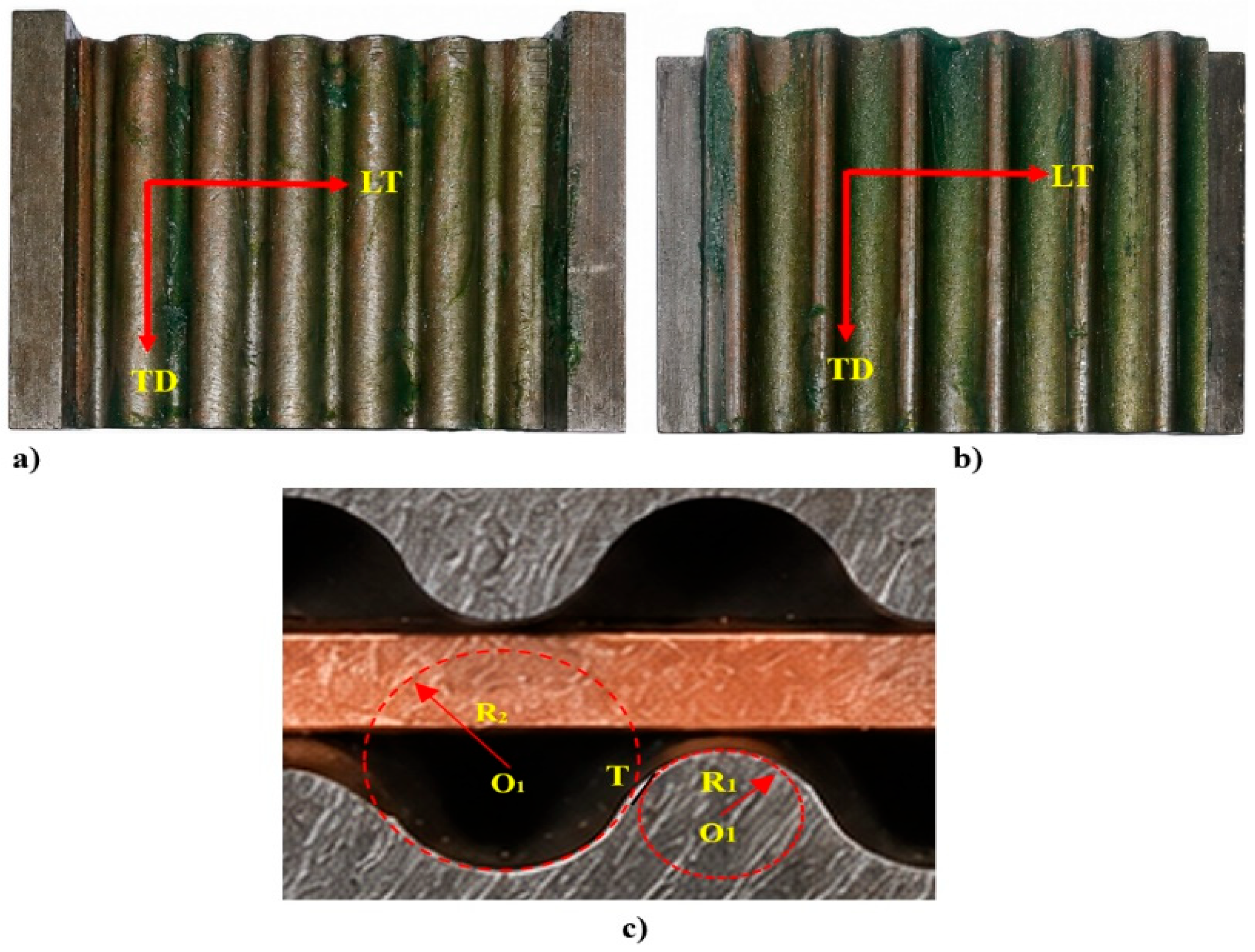
Figure 2 shows the fabricated modified die together with a cross-sectional view, in which the two tangent arcs R1 and R2, their centres, and the common tangent point T are visible. Following this profile, the MCGP tooling was machined from CK60 tool steel and finished by wire EDM; the fabricated tooling assembly is shown in Figure 3.

2.3. Analytical Strain in Conventional CGP

The deformation imposed by the conventional CGP die is idealised as plane-strain simple shear localised in the inclined groove region. For a groove angle φ, the engineering shear strain generated in one effective shearing operation is γ   =   t a n   φ , and the corresponding von Mises equivalent strain is ε e q   =   γ / 3   [3,5]. For the present 45° die, γ   =   t a n   45 °   =   1 , so that a single effective shearing stage imposes an ideal equivalent strain of ε e q , p a s s = 1 / 3     0.577 . This value is widely reported for CGP dies with a 45° groove angle [3,5]. One complete CGP pass comprises two grooving and two flattening operations [5]. Within the ideal shear formulation, each grooving–flattening sequence contributes two effective shear increments, so that the accumulated equivalent strain after one complete pass is ε e q , p a s s = 2 ε e q , s t a g e = 2 0.577     1.16 . More generally, after N passes the ideal accumulated strain is ε e q , t o t a l = 2 N · t a n   φ / 3 , which for φ = 45° and N = 1 again yields 1.16. In the present study the total groove depth (from crest to valley) equals the sheet thickness (3 mm), consistent with the conventional CGP design rule [3]; the crest depth from the flat surface is therefore 1.5 mm (half the total groove depth). The shear strain therefore remains γ = 1 and the theoretical equivalent strain after one complete conventional CGP pass is 1.16. Unlike the conventional die, the proposed MCGP die replaces the sharp crest and valley junctions with two tangent arcs of different radii, so that a single shear angle no longer describes the local deformation. The strain contribution of each arc must therefore be evaluated locally from a curvature-based bending formulation, as developed in the following section.

2.4. Strain Induced in MCGP

The strain imposed by the curved-groove geometry is evaluated following Hill’s general theory of bending [25]. For an element located at radius r in a sheet of thickness t, the true tangential strain is:
ε θ   =   l n r   +   t r   +   0.5 t
where r is the local arc radius of the die and t is the sheet thickness. In plane-strain bending, the width of the sheet is much larger than its thickness, so the change in width is negligible and the deformation is governed by the through-thickness and tangential strains. Introducing the plastic-anisotropy (R) values measured along (R0) and transverse to (R90) the rolling direction, the effective plastic strain produced in a single pressing is
ε e f f = 2 3 R 90 + 1 1 + R 0 + R 0 R 90 1 + R 0 + R 90 × ε θ
For an isotropic material, R0 = R90 = 1, and since one complete pass consists of two grooving and two flattening stages, the per-pass effective strain reduces to
ε e f f = 4 × 2 3 × l n r + t r + 0.5 t
The proposed MCGP die preserves both the nominal 45° groove angle and the 3 mm groove depth of the conventional die, so the nominal shear-based strain of one complete pass remains 1.16, identical to conventional CGP. The modification does not alter the nominal groove angle; it replaces the sharp crest and valley corners with two tangent circular arcs of different radii, a smaller radius R1 = 1.6 mm at the crest and a larger radius R2 = 4.8 mm at the valley. Unlike a constant-radius pressing die, the dual-radius MCGP profile cannot be represented by a single curvature radius. The contribution of the two curved junctions is therefore evaluated locally and reported as a set of local strain indicators that describe how the modified die redistributes deformation, rather than as a replacement for the nominal 1.16 value. Assuming isotropic plastic deformation (R0 = R90 = 1), the local effective bending strain associated with a curvature zone of radius Ri reduces from Equation (7) to
ε b , e q , i = 2 3 l n R i + t R i + 0.5 t
Equation (9) is evaluated separately for the crest radius R1 and the valley radius R2, since the dual-radius profile contains two curvature zones that cannot be represented by a single radius; the resulting local tangential and effective bending strains for each zone are reported in Table 2. If a material element is assumed to experience both curvature zones sequentially during one pressing event, an upper-bound dual-radius strain index further be defined as
ε b , e q , d u a l = 2 3 l n R 1 + t R 1 + 0.5 t + l n R 2 + t R 2 + 0.5 t
These curvature-based values are local analytical strain indicators only. They must not be added to the conventional CGP nominal strain of 1.16 as if they were uniform strain values imposed throughout the whole sheet: the value 1.16 describes the ideal nominal shear strain of one complete 45° CGP pass, whereas the local bending strains obtained from Equations (9) and (10) describe the bending severity introduced by the finite radii of the modified crest and valley junctions. These curvature-based values are local analytical strain indicators only. They must not be added to the conventional CGP nominal strain of 1.16 as if they were uniform strain values imposed throughout the whole sheet: the value 1.16 describes the ideal nominal shear strain of one complete 45° CGP pass, whereas the local bending strains obtained from Equations (9) and (10) describe the bending severity introduced by the finite radii of the modified crest and valley junctions. The corresponding numerical values for each curvature zone are reported in Table 2. The actual equivalent plastic strain distribution is therefore resolved by the finite element simulation of Section 3.
The analytical strain values for the conventional CGP die and the local curvature-based bending indicators for the proposed MCGP die are summarized in Table 2. It is emphasised that the local bending strains reported in Table 2 are not additive to the nominal shear strain of 1.16; they describe the local deformation severity at the curved junctions, while the nominal strain remains the global measure of deformation per pass.

2.5. Microhardness Measurement

The hardness distribution across the thickness of the annealed, conventional-CGP, and modified-CGP processed DHP copper sheets was evaluated using a Shimadzu Type M Vickers microhardness tester (Shimadzu Corporation, Kyoto, Japan) according to the ASTM E384 standard [26]. The measurements were performed under an applied load of 50 gf and a dwell time of 15 s. Prior to testing, the specimens were metallographically prepared through standard grinding and polishing procedures. Microhardness measurements were carried out on the polished cross-section at three characteristic regions across the sheet thickness, namely the upper, middle, and lower sections. For each region, six indentations were performed at intervals of 300 μm, resulting in a total of eighteen measurements for each specimen. The average hardness value and standard deviation were subsequently calculated and reported. This procedure enabled the evaluation of both the local hardness variation and the hardness homogeneity induced by the conventional-CGP and modified-CGP processing routes [8,9].

2.6. Tensile Testing

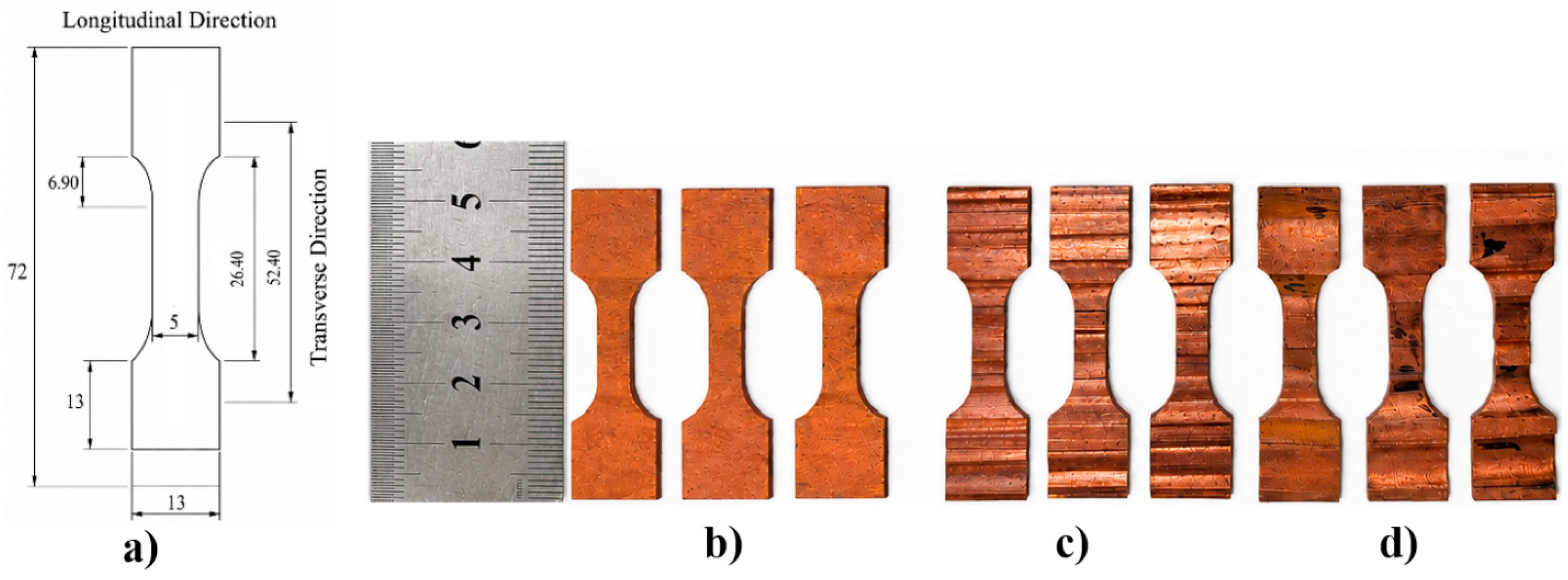
The tensile behaviour of the as-received, CGP-processed, and modified-CGP-processed DHP copper sheets was evaluated in accordance with ASTM E8/E8M [27]. Because the processed sheets were small (each 75 mm × 58 mm × 3 mm), sub-size specimens were used. Three specimens, each 58 mm long and 13 mm wide and retaining the full 3 mm sheet thickness, were extracted from every sheet along the transverse direction (perpendicular to the grooves) so as to capture the effect of the imposed plastic deformation on the mechanical response; their geometry and dimensions are given in Figure 4a, and the machined specimens for the as-received, CGP, and MCGP conditions are shown in Figure 4b–d. To eliminate the residual stresses and thermal damage, the specimens were cut by wire electrical discharge machining (WEDM) on a DK7745F machine (China), which produced a surface roughness of approximately Ra = 0.5 μm. The tests were conducted at room temperature on a SANTAM STM-50 universal testing machine (SANTAM Co., Tehran, Iran) fitted with a 50 kN load cell, at a constant crosshead speed of 0.5 mm/min. Engineering stress–strain curves were derived from the recorded load–displacement data, and the yield strength, ultimate tensile strength, and total elongation were determined for each condition. At least three specimens were tested per condition to ensure repeatability.

2.7. Finite Element Modelling

Finite element simulations were performed in Abaqus/Explicit 2021 (Dassault Systèmes Simulia Corp., Johnston, RI, USA) to resolve the strain distribution developed during the grooving stage of the conventional CGP and the proposed MCGP processes. The material properties used in the simulation, specifically, the true stress–plastic strain curve, were derived from the tensile tests of the annealed material reported in Section 2.6 and presented in Section 3.2. The equivalent plastic strain (PEEQ) contours and through-thickness profiles obtained from the FEM analysis are compared with the experimental hardness and tensile results to validate the deformation kinematics predicted by the model. Because grooving is the primary deformation stage of the CGP route, the equivalent plastic strain obtained from this single stage was taken as the basis for estimating the strain accumulated after one complete pass: in accordance with the analytical treatment of the dies (Section 2.2), one complete pass comprises two grooving and two flattening operations, so that the per-pass strain follows directly from the grooving-stage field. However, it is acknowledged that the FEM results presented here are for a single grooving stage only; a full simulation of the complete pass (including flattening and sample rotation) would be required for a complete description of the strain history. This is a limitation of the present study and is addressed in the discussion of the results. The copper sheet was modelled as a deformable body, whereas the upper and lower dies were defined as rigid surfaces. The mechanical response of the DHP copper was described by an elastic–plastic constitutive model with isotropic strain hardening, using a Young’s modulus of 118 GPa, a Poisson’s ratio of 0.34, and a density of 8960 kg·m−3. The isotropic hardening model was selected because it is the simplest and most computationally efficient model that captures the essential work-hardening behaviour of the material for the purpose of comparing the deformation kinematics of the two die geometries. For the scope of this study, comparing the strain distribution and deformation patterns, the isotropic hardening assumption is considered appropriate. Future work incorporating kinematic or mixed hardening could provide more accurate predictions of residual stresses and springback. Plastic deformation was prescribed through the true stress–plastic strain curve derived from the tensile response of the annealed material.
The engineering stress–strain data measured in tension were converted into true stress and true strain through
σ t r u e   = σ e n g   1 + ε e n g
ε t r u e = l n 1 + ε e n g
and the corresponding plastic strain was obtained by subtracting the elastic component,
ε p = ε t r u e σ t r u e / E
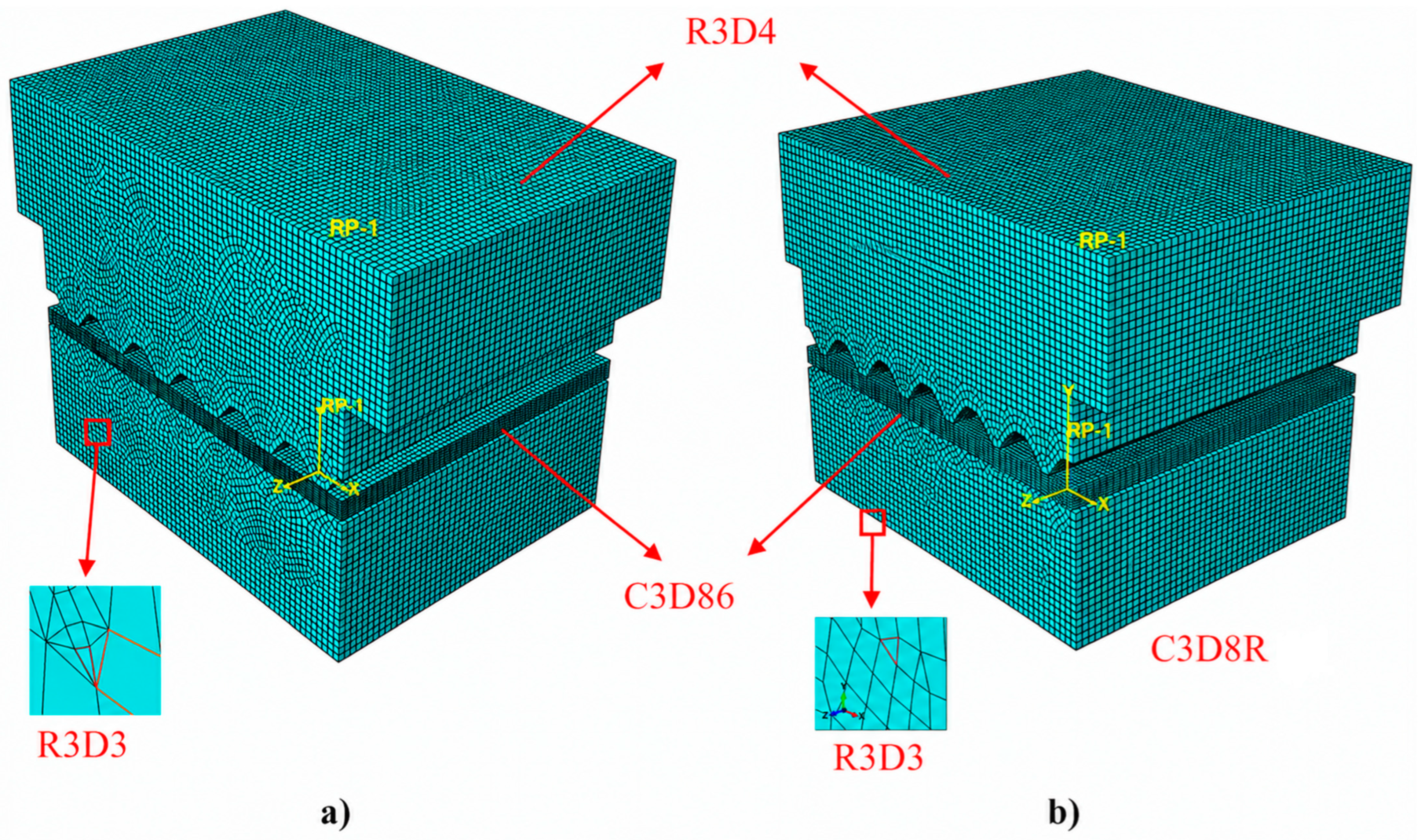
To reproduce the constrained conditions of the grooving operation, the lower die was fully fixed. Reflecting the longitudinal engagement of the sheet within the fixture in the constrained-groove process, the two lateral edges of the sheet were restrained in the longitudinal direction (UX = 0), while the remaining degrees of freedom were left free; the upper die was permitted to translate only in the vertical (pressing) direction. In MCGP, the upper die was driven downward through a total stroke of 4 mm, equal to the total groove depth of 3 mm (matching the sheet thickness) plus the 1 mm clearance retained between the mating dies, so as to complete one grooving stroke. Because constrained groove pressing is a low-speed forming operation, it was treated as quasi-static and solved with the dynamic-explicit procedure [11,28]; the stroke was therefore applied as a constant vertical velocity ramped smoothly from zero through a smooth-step amplitude, which suppresses the initial impact and the spurious stress waves that an abrupt velocity onset would otherwise introduce. The punch velocity was kept sufficiently low so that the kinetic energy remained negligible relative to the internal energy throughout the step, thereby preserving quasi-static equilibrium. Throughout the simulation, the ratio of kinetic to internal energy (ALLKE/ALLIE) was monitored throughout and remained well below the 5% threshold conventionally adopted for quasi-static validity, confirming that inertial effects were negligible and that the dynamic-explicit solution represents a quasi-static deformation. Owing to the lubricant (grease) applied during processing to minimise friction, idealised frictionless contact was assumed at all die-sheet interfaces. For typical grease-lubricated metal-forming operations, the coefficient of friction (μ) is generally in the range of 0.05–0.15. A small but non-zero friction coefficient would introduce additional shear tractions at the sheet surfaces, which could moderately increase the peak PEEQ values (by approximately 5–15%) and slightly increase the strain gradients near the die–sheet contact regions. However, the qualitative conclusions regarding the relative differences between conventional CGP and MCGP, specifically, the lower peak PEEQ and more distributed strain for MCGP, would remain unchanged, as the friction effects would be similar for both die geometries. It is acknowledged that complete frictionless conditions are unattainable experimentally and that residual friction contributes to additional shear tractions at the sheet surfaces; this limitation is addressed in the discussion of the FEM–experimental comparison (Section 3.2). The copper sheet was discretised with eight-node linear hexahedral elements with reduced integration (C3D8R), whereas the rigid dies were represented by four-node (R3D4) and three-node (R3D3) rigid-surface elements. A mesh-convergence study on the peak equivalent plastic strain confirmed numerical accuracy: convergence was reached with 89,856 C3D8R elements for the conventional CGP model and 59,136 for the MCGP model, beyond which further refinement had no significant effect. The groove regions, where the deformation and strain gradients are most severe, were meshed more finely than the lightly deformed regions away from the grooves to balance accuracy against computational cost. The element types, die geometries, and resulting mesh distributions adopted for both the conventional CGP and MCGP models are shown in Figure 5.
The deformation was quantified through the equivalent plastic strain (PEEQ), defined as:
P E E Q   =   [ ( 2 / 3 ) ( ( ε 1 p ) 2   +   ( ε 2 p ) 2   +   ( ε 3 p ) 2 )
where ε 1 p , ε 2 p and ε 3 p are the principal plastic strain components.
The PEEQ contours obtained at the end of the grooving stage were then used to compare the two die geometries in terms of their strain-accumulation capability and the homogeneity of the resulting deformation field.

2.8. X-Ray Diffraction and Microstructural Analysis

The microstructural evolution of the Cu-DHP copper in the as-received, conventional-CGP, and modified-CGP conditions was characterised by X-ray diffraction (XRD), optical microscopy (OM), and field-emission scanning electron microscopy (FE-SEM) using a TESCAN MIRA3 instrument (TESCAN Orsay Holding a.s., Brno, Czech Republic). The metallographic observations were used to examine the grain morphology and deformation-induced fragmentation, whereas the XRD line broadening was used to evaluate the scale of the coherently diffracting domains in the processed material. XRD measurements for the CGP and modified-CGP specimens were conducted using an X’Pert PRO diffractometer (PANalytical B.V., Almelo, The Netherlands) in θ-θ geometry with a Cu anode. Patterns were recorded at 25 °C over 2 θ   =   5.0131 79.9711 ° in continuous mode with a step size of 0.0260°, a fixed divergence slit of 1.0°, and generator settings of 40 kV and 40 mA. The characteristic wavelengths were K α 1   =   1.54060   Å and K α 2   =   1.54443   Å . Because an experimental as-received scan was unavailable, a simulated FCC-Cu reference profile containing the Cu(111), Cu(200), and Cu(220) reflections was generated over the same 2θ range and step size. This reference profile was not used to determine the actual grain size of the annealed material. The Cu(111), Cu(200), and Cu(220) peaks of the experimental patterns were fitted locally using a pseudo-Voigt profile after background subtraction. The full width at half maximum (FWHM) was converted to radians before calculation. Since instrumental broadening was not determined using a standard reference material (e.g., LaB6 or silicon powder), the calculated values are reported as apparent, instrument-uncalibrated coherent diffraction-domain sizes and are used exclusively for comparative purposes between the conventional CGP and MCGP conditions, rather than as absolute grain-size measurements. A rigorous absolute determination of domain size would require calibration of the instrument-specific broadening contribution using a standard material; this is acknowledged as a limitation of the present study. Interplanar spacing was calculated using Bragg’s law [29]:
n λ   =   2 d   s i n θ
For FCC copper, the lattice parameter was calculated from
d hkl = a h 2 + k 2 + l 2 ,   a = d hkl / h 2 + k 2 + l 2
The apparent coherent diffraction-domain size was estimated using the Scherrer equation [29]:
D   =   K λ / β   c o s θ
where D is the coherent diffraction-domain size, K = 0.9, λ = 0.154060 nm, β is FWHM in radians, and θ is the Bragg angle. It must be emphasised that these values are instrument-uncalibrated and are presented only for relative comparison between the two processing conditions. This quantity is not equivalent to the metallographic grain diameter; X-ray line broadening reflects the size of coherently diffracting domains delimited by subgrain boundaries, dislocation cells, and other lattice defects, and is therefore generally smaller than the true grain size [30]. Furthermore, the absence of instrumental broadening correction means that the reported domain sizes are overestimated in terms of refinement; only the relative difference between the CGP and MCGP conditions (approximately 17% finer for MCGP) should be considered as a reliable comparative indicator. A comparative defect-density index was calculated as
δ = 1 / D 2
The index δ was used only for relative comparison between CGP and modified CGP and should not be interpreted as an absolute dislocation density. The uncertainty in D was propagated from the fitted peak-width uncertainty, and Δ δ / δ   =   2 Δ D / D was used for the corresponding defect-density uncertainty. For metallographic examination, specimens sectioned from each condition were mounted, ground on successive grades of SiC abrasive paper, polished to a mirror finish with fine alumina and diamond suspensions, and chemically etched with a copper etchant to reveal the grain boundaries and deformation-induced features. The polished and etched cross-sections were then examined by optical microscopy at a scale of 50 µm to compare the grain morphology, deformation bands, twinning-like features, and grain subdivision. SEM observations were performed at high magnification using secondary-electron imaging; because the SEM contrast is primarily topographic and the grain boundaries are not fully resolved, the SEM images were interpreted in terms of nanoscale surface morphology and deformation-induced features rather than direct grain-size measurement.

3. Results and Discussion

3.1. Microhardness and Deformation Homogeneity

Microhardness provides a spatially resolved measure of both the local hardening produced by each processing route and the uniformity of that hardening through the sheet thickness, the latter being decisive for the in-service reliability of DHP copper components. For every specimen, Vickers indentations were recorded in the upper, middle, and lower regions [26], and the data were used to evaluate the mean hardness, its standard deviation, and the degree of hardness inhomogeneity. The mean hardness of each condition was obtained as
HV avg = 1 n   i = 1 n HV i
where H V a v g is the mean hardness, H V i the measured hardness values, and n is the number of measurements. The scatter of the measurements was quantified by the standard deviation [8,9],
SD = i = 1 n HV i HV avg 2 / n 1
and the relative hardness non-uniformity was expressed through an inhomogeneity factor (IF) [8,9],
IF = SD HV avg × 100
in which a lower IF denotes a more uniform hardness field and a higher IF reflects greater local variation arising from non-uniform plastic flow.
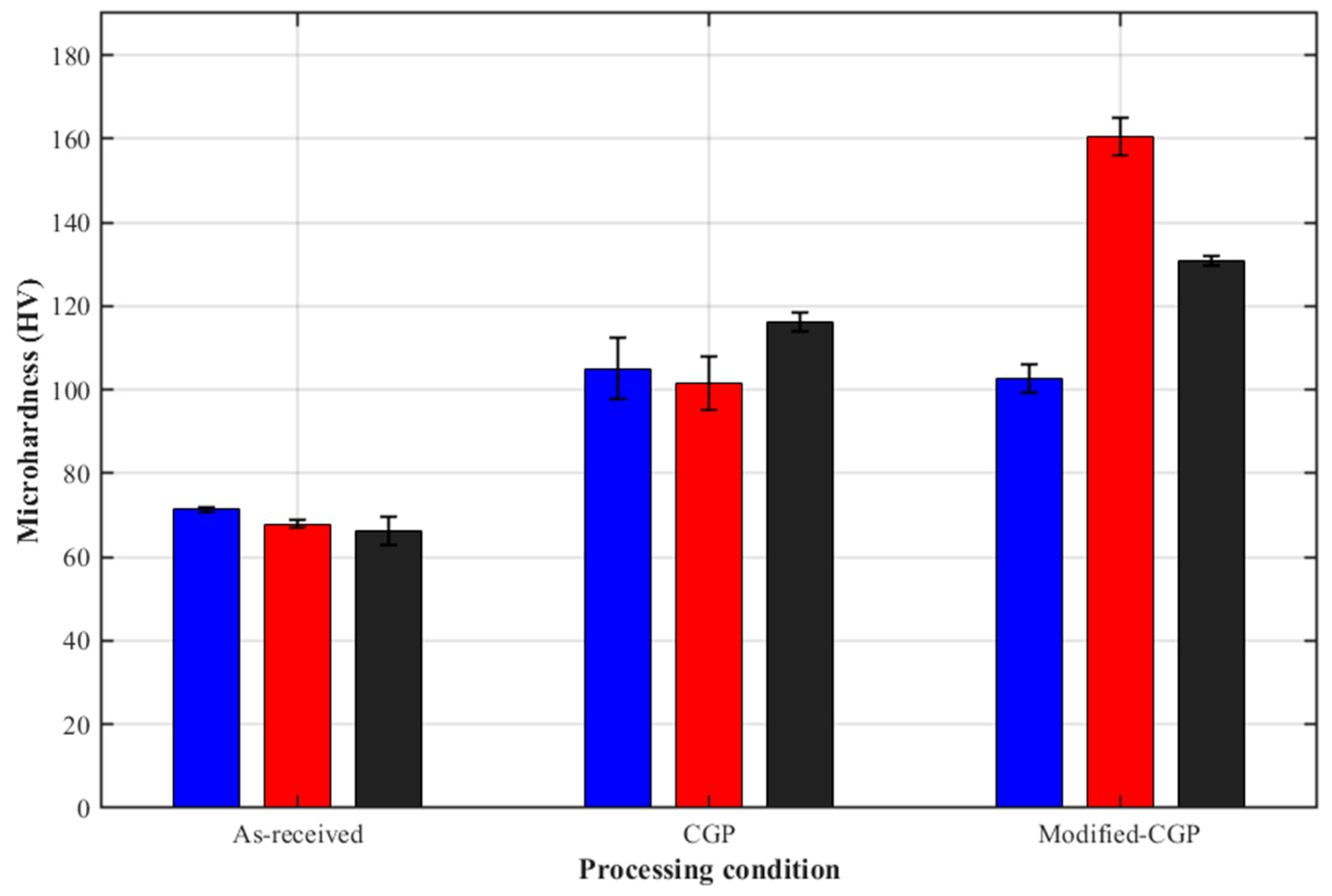
Figure 6 compares the regional hardness measured in the upper, middle, and lower regions of the as-received, conventional CGP, and MCGP specimens; the error bars denote the standard deviation of six indentations per region. In the as-received condition the three regions showed closely matched values (≈66–71 HV; mean ± SD), confirming a nearly homogeneous starting microstructure. Both deformation routes raised the hardness substantially, but the regional balance differed markedly between them. Conventional CGP produced only a moderate spread between regions, with the lower region slightly harder than the upper and middle, whereas MCGP generated a pronounced regional contrast in which the mid-thickness region reached the highest hardness (≈160 HV).
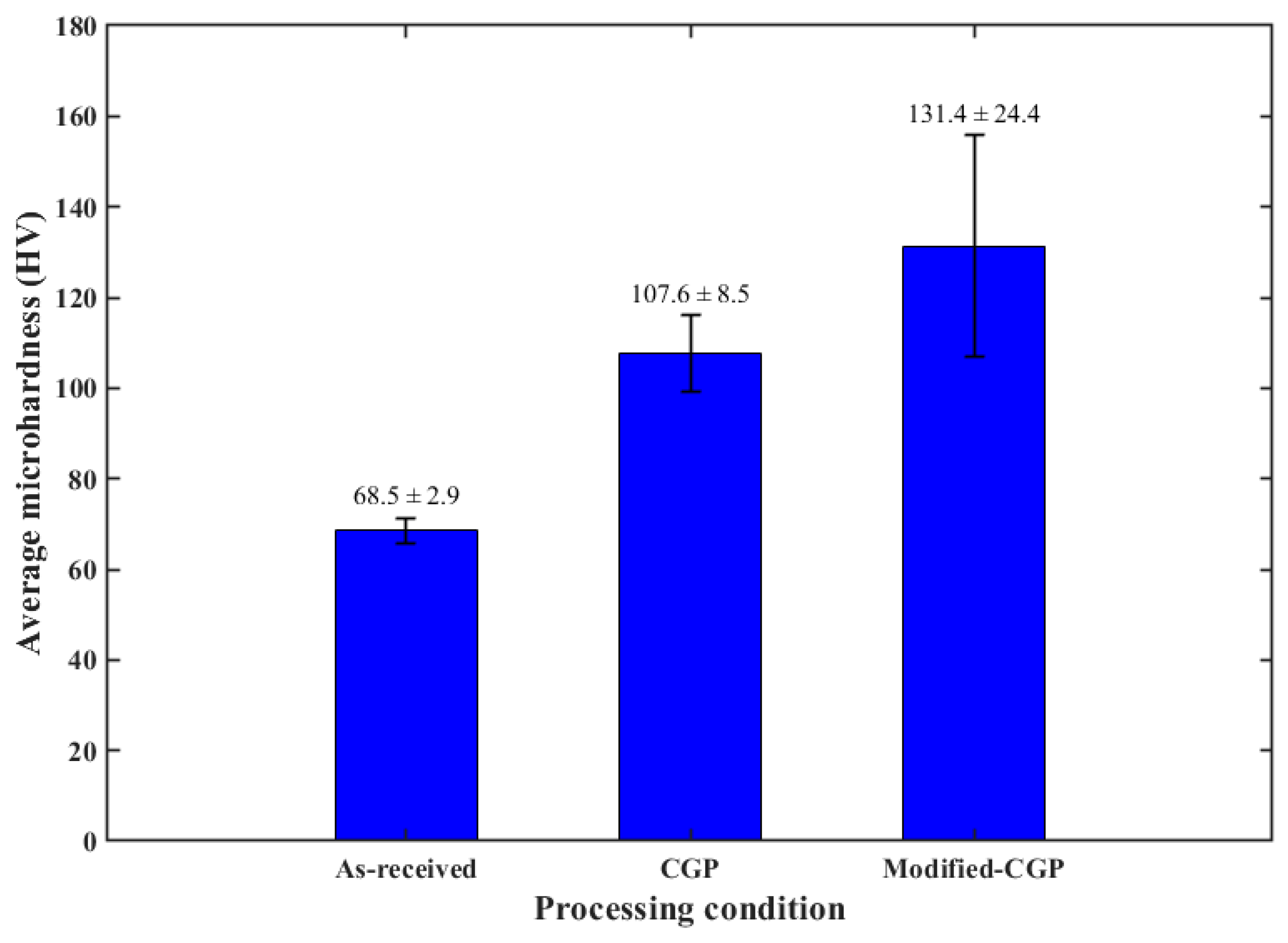
The mean hardness values of the three conditions are compared in Figure 7, where the error bars represent the standard deviation of all eighteen indentations per specimen. The as-received copper exhibited a baseline hardness of 68.50 ± 2.9 HV (n = 18). Conventional CGP raised the mean hardness to 107.62 ± 8.5 HV (n = 18), an increase of approximately 57.1%, which is attributed to the strain hardening accumulated during the repeated grooving and flattening stages [10].
The MCGP specimen attained the highest mean hardness, 131.38 ± 24.4 HV (n = 18), corresponding to increases of approximately 91.8% relative to the as-received state and 22.1% relative to conventional CGP. This larger hardening response is consistent with the higher equivalent plastic strain imposed by the MCGP die during the grooving stage (FEM peak PEEQ ≈ 0.395 for MCGP versus ≈ 0.586 for conventional CGP, as shown in Section 3.3). It is emphasised that these values are for a single grooving stage; a complete CGP pass comprises two grooving and two flattening stages, so the cumulative strain is higher. However, the relative ranking of the two processes (MCGP > conventional CGP) is consistent across the single-stage FEM results and the experimental hardness measurements. Notably, the considerably larger standard deviation of the MCGP specimen (±24.4 HV) already indicates a wider hardness distribution, which is examined in detail below.
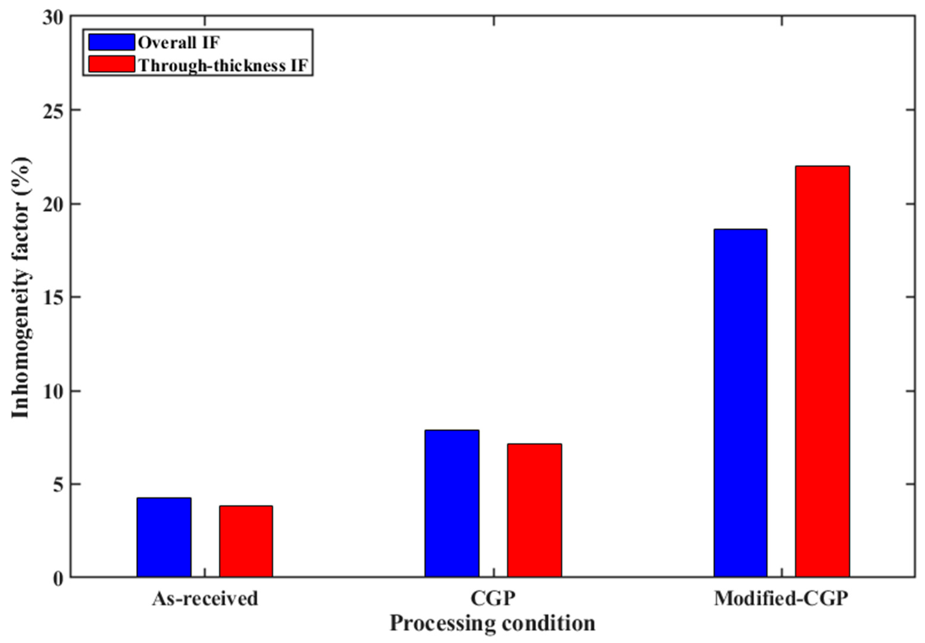
The overall and through-thickness inhomogeneity factors of the three conditions are compared in Figure 8. The overall IF increased from 4.60% ± 0.5% in the as-received state to 7.85% ± 0.8% after conventional CGP and to 18.60% ± 1.2% after MCGP, while the corresponding through-thickness IF rose from 3.82% ± 0.4% to 7.14% ± 0.7% and 21.97% ± 1.5%, respectively. The systematic growth of IF with processing confirms that severe plastic deformation introduces through-thickness strain gradients into the sheet [8]. The markedly higher IF of the MCGP specimen originates primarily from the elevated hardness of the mid-thickness region rather than from random measurement scatter, as corroborated by the regional and longitudinal profiles in Figure 6 and Figure 9.
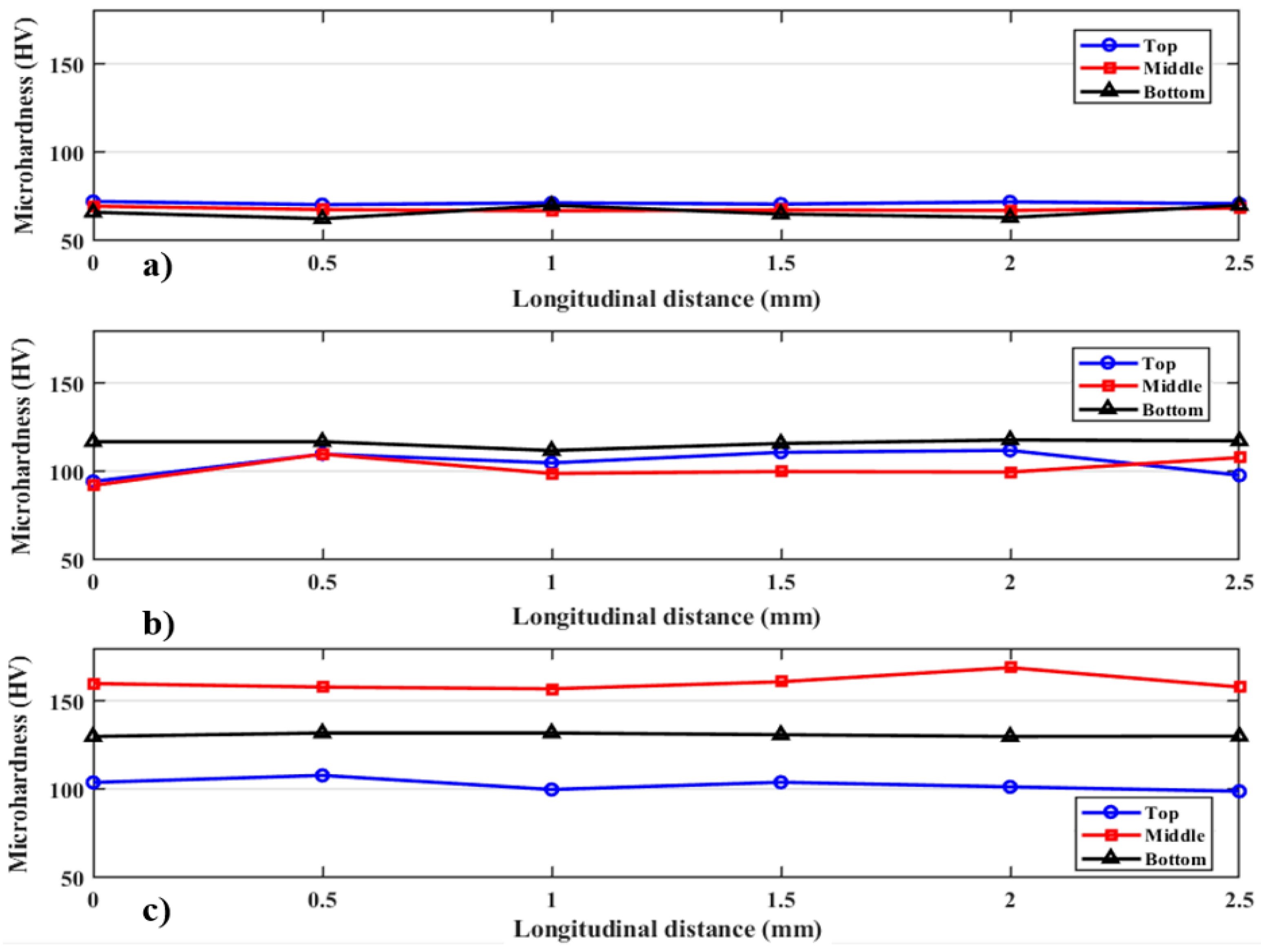
The longitudinal hardness profiles, measured at 0.5 mm intervals in the upper, middle, and lower regions, are presented in Figure 9. The as-received specimen (Figure 9a) displayed only minor fluctuations about its baseline, consistent with its uniform initial microstructure, whereas both processed conditions developed clear region-to-region differences. In conventional CGP (Figure 9b) the lower region remained consistently harder than the upper and middle regions, indicating a moderate, one-sided strain accumulation across the thickness. In MCGP (Figure 9c) the contrast was considerably stronger: the mid-thickness region exhibited the highest hardness (≈155–170 HV), well above the lower (≈130 HV) and upper (≈100 HV) regions, pointing to intense strain accumulation in the central deformation zone.
The hardening produced by both routes can be rationalised in terms of dislocation storage during severe plastic deformation. As straining proceeds, the dislocation density rises and interactions intensify, increasing the resistance to further slip. This dependence is captured by the Taylor relation [31]
σ = σ 0 + α   G   b   ρ
where σ is the flow stress, σ0 the friction stress, α a material constant, G the shear modulus, b the Burgers vector, and ρ the dislocation density. The hardness increments measured after CGP and MCGP processing are therefore consistent with progressive dislocation multiplication, grain subdivision, and microstructural refinement [1,4]. Overall, both processes effectively strengthen the DHP copper sheet, with MCGP delivering the larger hardening response owing to its greater strain-accumulation capacity; the accompanying rise in through-thickness IF, however, indicates that this additional strengthening is concentrated in the central deformation zone rather than distributed uniformly across the thickness.

3.2. Tensile Behaviour and Mechanical Properties

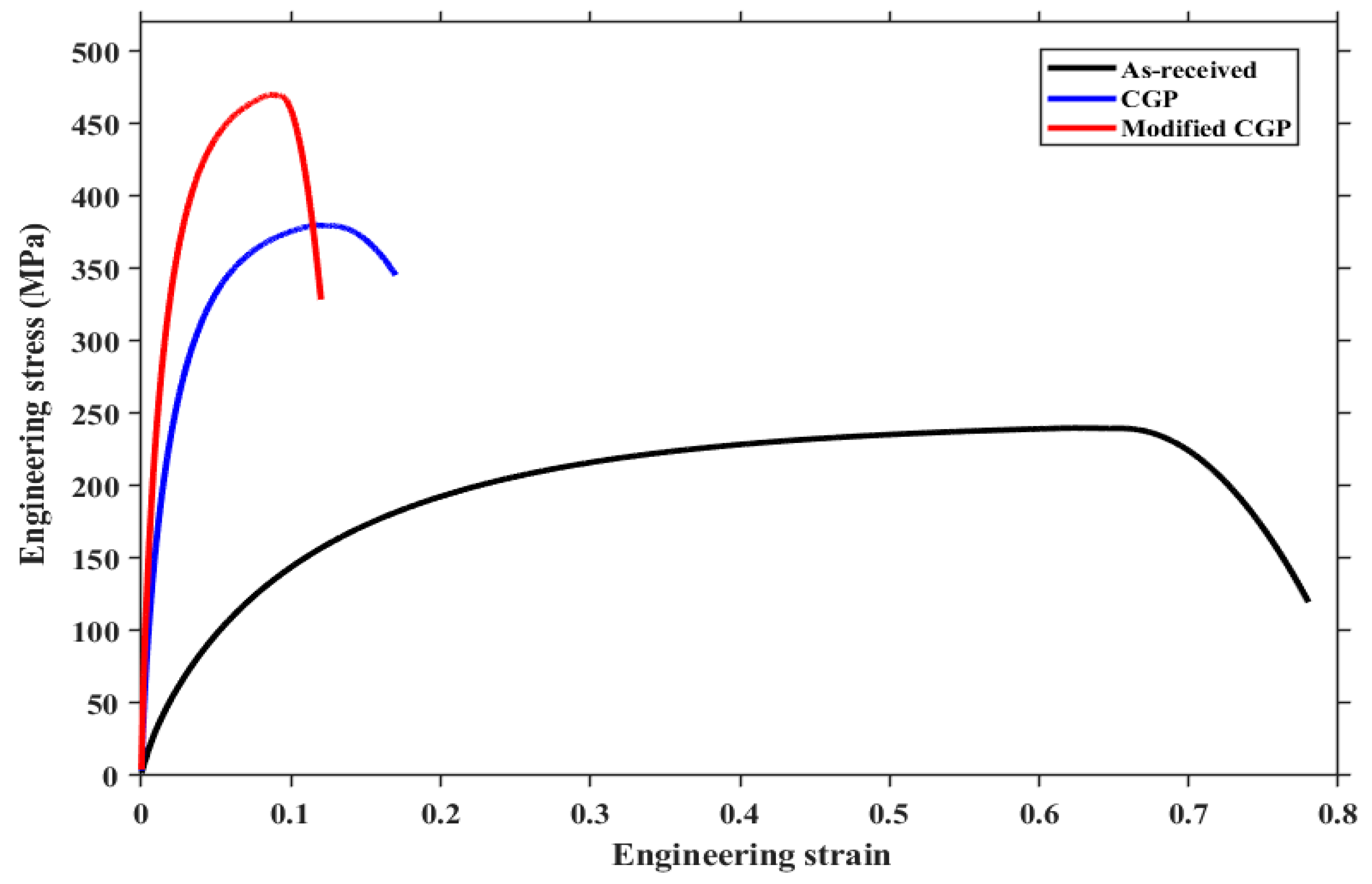
Figure 10 presents the average engineering stress–strain curves of the as-received, conventional CGP, and modified CGP (MCGP) specimens, each curve representing the mean of three independent tensile tests [27]. The as-received material exhibited the lowest flow stress and the largest tensile strain, whereas both processed conditions showed a pronounced upward shift in the stress–strain response, reflecting the work hardening and grain refinement introduced by severe plastic deformation. Conventional CGP raised the ultimate tensile strength (UTS) from 230.06 MPa in the as-received state to 365.03 MPa, while the MCGP specimen exhibited the highest response, reaching 451.94 MPa. This strengthening was accompanied by a progressive loss of ductility, the total elongation decreasing from 77.94% in the as-received condition to 16.96% and 12.15% after conventional CGP and MCGP processing, respectively.
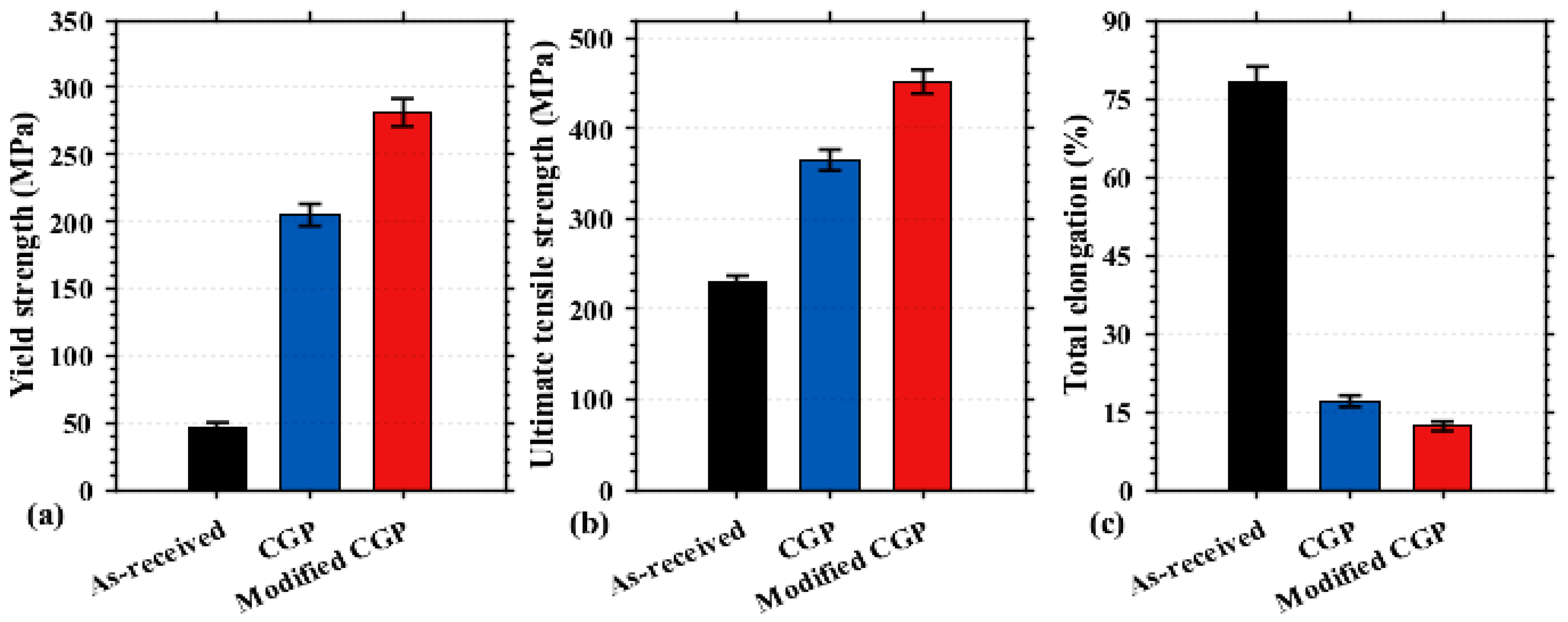
The tensile properties are summarised in Figure 11 as mean ± standard deviation (n = 3). The yield strength (Figure 11a) increased from 46.66 ± 3.2 MPa in the as-received condition to 204.79 ± 8.5 MPa after conventional CGP and to 281.19 ± 9.1 MPa after MCGP (mean ± SD, n = 3), corresponding to gains of approximately 339% and 503%, respectively, relative to the as-received material. The MCGP specimen therefore exhibited a yield strength about 76.40 MPa (37.3%) higher than that of conventional CGP. A comparable trend was observed for the ultimate tensile strength (Figure 11b). Conventional CGP increased the UTS from 230.06 ± 5.2 MPa to 365.03 ± 7.8 MPa (≈58.7%), and MCGP raised it further to 451.94 ± 8.4 MPa (mean ± SD, n = 3), approximately 96.4% above the as-received condition and 23.8% above conventional CGP. The superior strength of the MCGP specimen is consistent with the higher equivalent plastic strain imposed by the modified die during the grooving stage. The FEM analysis (Section 3.3) shows that the MCGP die produces a peak PEEQ of approximately 0.395 during a single grooving stage, compared with approximately 0.586 for conventional CGP. While these values are for a single grooving stage, the relative ranking (MCGP > conventional CGP) is consistent with the experimental tensile results. The higher strain accumulation in MCGP is attributed to the more effective deformation imposed by the graded-curvature profile. This additional straining accounts for the 37.3% and 23.8% gains in yield and ultimate tensile strength, respectively, noted above, indicating that the graded-curvature geometry imposes more effective deformation per pass. As expected, these strength gains were accompanied by a reduction in ductility (Figure 11c). The total elongation fell from 77.94 ± 3.5% in the as-received condition to 16.96 ± 1.2% after conventional CGP and to 12.15 ± 0.9% after MCGP (mean ± SD, n = 3), corresponding to reductions of approximately 78.2% and 84.4%, respectively; the MCGP elongation was about 28.4% lower than that of conventional CGP. This strength–ductility trade-off is characteristic of severe plastic deformation, in which dislocation accumulation and grain refinement raise strength at the expense of uniform elongation [1,4].

3.3. Finite-Element PEEQ Contours During the Grooving Stage

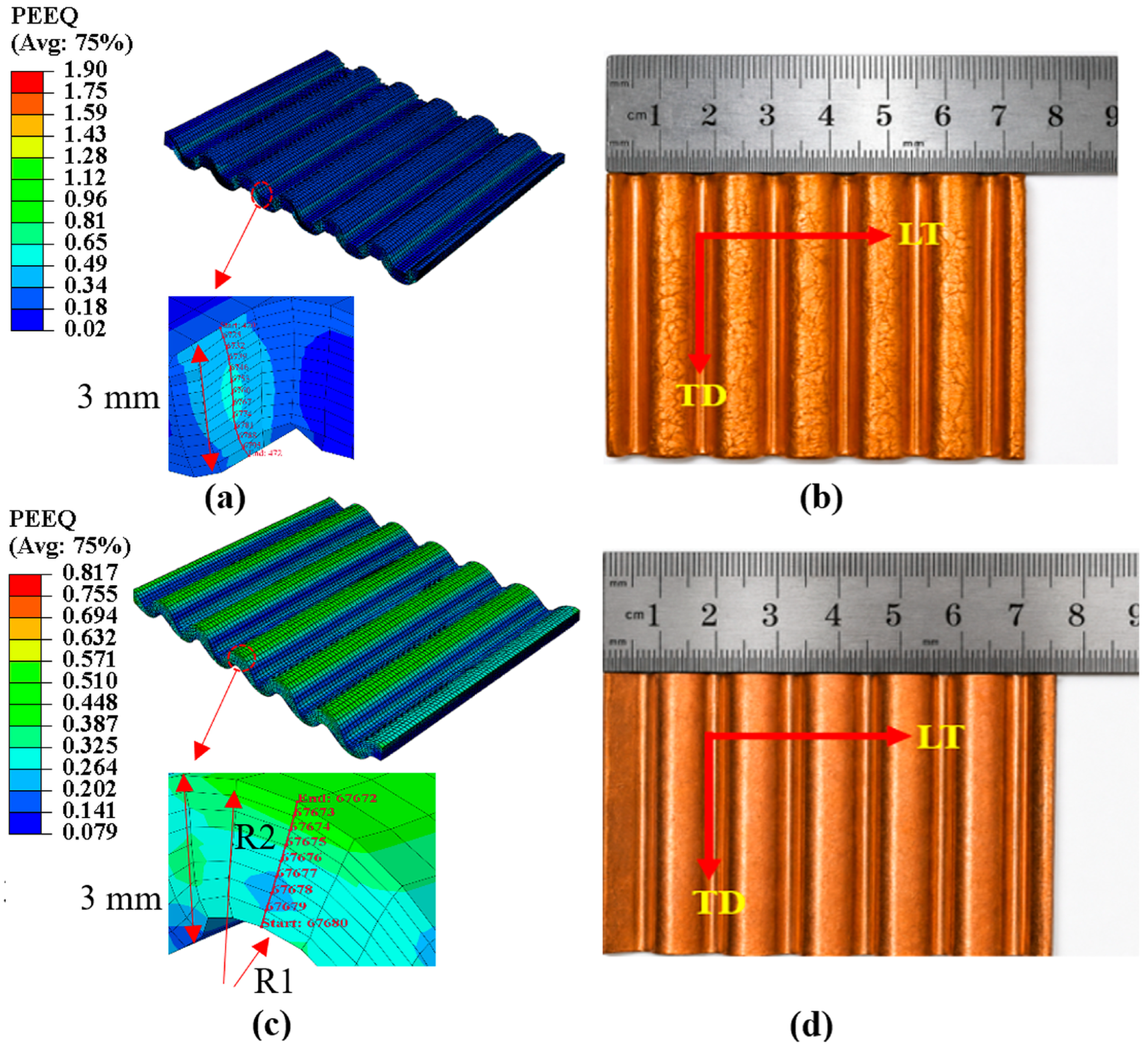
The finite-element PEEQ contours for the grooving stage of the conventional and modified CGP configurations are presented in Figure 12a,c, respectively, together with the corresponding actual grooved specimens shown in Figure 12b,d. In the conventional CGP configuration, shown in Figure 12a, the plastic-strain field is distributed almost symmetrically with respect to the sheet mid-plane, and the highest PEEQ region is concentrated around the central deformation zone [11,28]. This distribution is consistent with the symmetric groove geometry and the balanced local contact conditions on both sides of the sheet. In contrast, the modified CGP configuration, shown in Figure 12c, exhibits a distinctly asymmetric strain field. The higher PEEQ region is shifted toward the smaller-radius side, R1 = 1.6 mm, while the larger-radius side, R2 = 4.8 mm, experiences a lower strain level. The 6 mm center-to-center spacing between the two radii creates a finite transition region between the two local curvature zones and prevents the deformation from being concentrated at a single symmetric location. The actual grooved shapes qualitatively follow the numerical deformation patterns, confirming the influence of the die geometry on the position and extent of local plastic-strain localization. In the corresponding experiments, shown in Figure 12b,d, the frictionless contact assumed in the finite-element model was experimentally approximated by applying a heat-resistant grease at the die–sheet interface; the longitudinal (LT) and transverse (TD) directions are marked on each specimen, and the residual lubricant film retained in Figure 12b confirms the lubricated, frictionless condition.
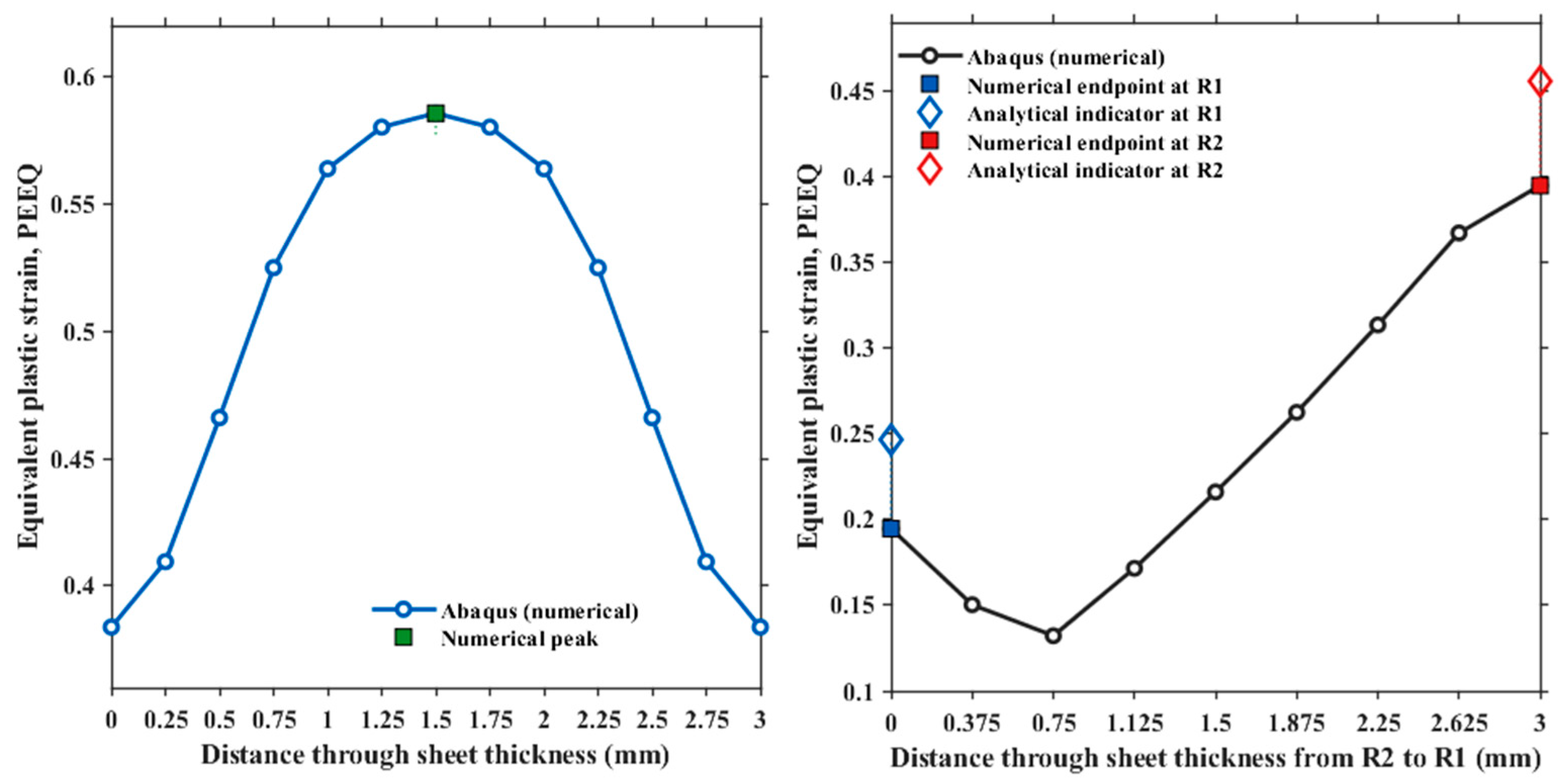
The local through-thickness PEEQ profiles obtained from the finite-element results are shown separately in Figure 13. For conventional CGP, the symmetrized profile increases from approximately 0.384 near the sheet surfaces to a maximum value of 0.586 at the mid-thickness. The difference between this numerical peak and the corresponding analytical local value of 0.577 [5,24] is only 1.43%, indicating that the central zone closely approaches the ideal local shear state. For the modified CGP configuration, the local profile is strongly non-symmetric. Along the full 3 mm thickness path from R2 to R1, PEEQ decreases from 0.195 to a minimum of 0.132 at x = 0.75 mm and then increases progressively to 0.395 at the small-radius side. The local numerical values at R2 and R1 differ from the corresponding analytical values by 21.06% and 13.34%, respectively. The smaller deviation at R1 indicates that the local analytical estimate becomes more representative in the region of stronger curvature, whereas the larger deviation at R2 reflects the more distributed deformation and the influence of the intermediate transition zone. Overall, the conventional geometry produces a symmetric central peak, while the modified geometry generates a controlled local strain gradient through the sheet thickness.
This difference in strain topology has a direct bearing on the microstructural and mechanical homogeneity. In conventional CGP the deformation is concentrated in a narrow symmetric band at the mid-thickness, where the numerical peak of 0.586 sits well above the surface value of 0.384; such a sharp through-thickness peak promotes localised grain refinement at the centre while leaving the near-surface material comparatively under-deformed, which accounts for the through-thickness hardness variation observed in the conventional CGP specimens. In the modified die the deformation is spread along the full 3 mm path between the two arcs, so that even the minimum value of 0.132 still represents meaningful plastic work and the rise toward the 0.395 peak is monotonic rather than spiked. The absence of a single dominant strain concentration would be expected to homogenise the through-thickness response, since the controlled gradient distributes dislocation generation more evenly through the thickness instead of saturating a thin central layer.
However, the measured through-thickness hardness showed the opposite trend: MCGP concentrated the additional hardening in the mid-thickness region and raised the inhomogeneity factor from 7.14% for conventional CGP to 21.97% (Section 3.1). This apparent paradox, a more distributed FEM strain field but higher hardness inhomogeneity, requires careful physical interpretation. Several factors contribute to this discrepancy:
First, the FEM model assumes idealised, frictionless contact at the die–sheet interfaces. In the experiments, despite the use of a heat-resistant grease to minimise friction, residual friction inevitably persists at the die–sheet contacts. This residual friction introduces additional shear tractions at the sheet surfaces, which can
  • Increase the severity of localised deformation near the contact regions.
  • Alter the through-thickness strain distribution by introducing surface shear that is not captured in the frictionless model.
  • Contribute to strain gradients that the idealised FEM model does not predict.
The frictionless assumption therefore represents an upper-bound estimate of deformation uniformity; the actual experimental conditions are expected to exhibit higher strain gradients due to residual friction effects.
Second, the FEM analysis captured only a single grooving stage, whereas the hardness IF reflects the cumulative effect of the entire CGP pass (two grooving and two flattening stages). Over the complete pass, the sheet is rotated 180° between grooving stages, so the strain gradients from the first grooving stage are superimposed onto those from the second. In the conventional symmetric die, this rotation effectively averages out the strain distribution, producing the relatively low IF (7.14%). In MCGP, the die geometry is asymmetric (R1 ≠ R2), so the strain distribution is also asymmetric; the 180° rotation does not perfectly compensate for this asymmetry, and the cumulative effect over the four stages is a concentration of strain in the mid-thickness region, raising the IF to 21.97%.
Third, the modified geometry redistributes rather than amplifies the nominal pass strain (≈1.16, unchanged from the conventional die). Because the total strain per pass is fixed, redistribution necessarily means that some regions experience higher cumulative strain than others within the same pass. The mid-thickness region, where the strain paths from R1 and R2 converge, accumulates more deformation than the near-surface regions, resulting in higher local hardness and higher IF.
In summary, the homogenisation anticipated from the FEM strain field was not realised within a single pass due to the combined effects of residual friction, cumulative strain asymmetry over successive stages, and the inherent redistribution of a fixed nominal strain. The frictionless FEM model, while useful for comparing the fundamental deformation kinematics of the two die geometries, provides an upper-bound estimate of uniformity. Incorporating realistic friction coefficients in future FEM models and optimizing the arc radii to better balance the through-thickness strain distribution remains objectives for further work.
From a processing standpoint, the lower peak PEEQ of the MCGP die also implies a reduced risk of local strain exhaustion and surface microcracking at the die–sheet contact, a consideration of particular relevance to DHP copper components intended for long-term marine service, where surface integrity governs corrosion-fatigue performance [17,24].

3.4. XRD and Microstructural Evolution

The crystallographic and microstructural evolution of the Cu-DHP sheets in the as-received, CGP-processed, and modified-CGP-processed conditions was evaluated using X-ray diffraction, optical microscopy, and high-magnification scanning electron microscopy. The XRD patterns are presented first to identify the phase constitution and quantify the evolution of diffraction-peak broadening, while the optical and SEM observations are subsequently used to interpret the corresponding changes in grain morphology, deformation substructure, and surface-scale features.
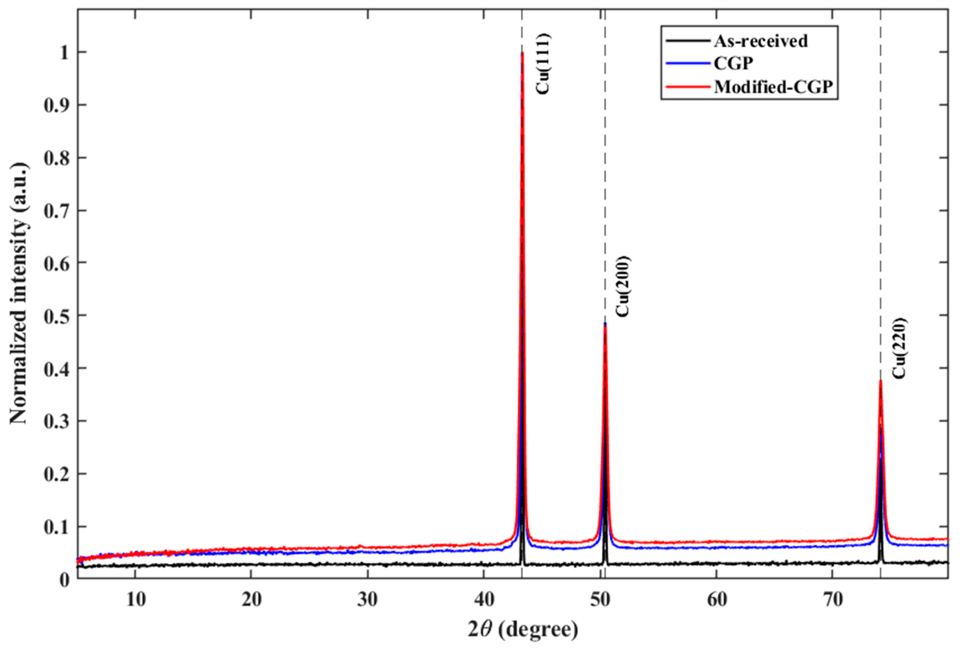
Figure 14 presents the normalized XRD patterns of the three conditions over the investigated 2θ range. Because an experimental diffraction pattern was not available for the as-received condition, the first curve represents a simulated/reference FCC-Cu profile generated over the same angular interval and step size as the experimental CGP and modified-CGP scans. This curve was used only as a crystallographic reference for peak-position and line-shape comparison and should not be interpreted as an independently measured experimental pattern.
The diffraction profiles of the processed samples exhibit the characteristic reflections of face-centred cubic copper, namely Cu(111), Cu(200), and Cu(220), located near 43.3°, 50.4°, and 74.1°, respectively [29]. The preservation of these reflections indicates that both CGP routes retained the FCC copper matrix and did not produce a detectable phase transformation. Therefore, the changes in hardness and microstructure are attributed primarily to deformation-induced refinement, dislocation accumulation, and the development of sub grain boundaries rather than to the formation of a new crystalline phase.
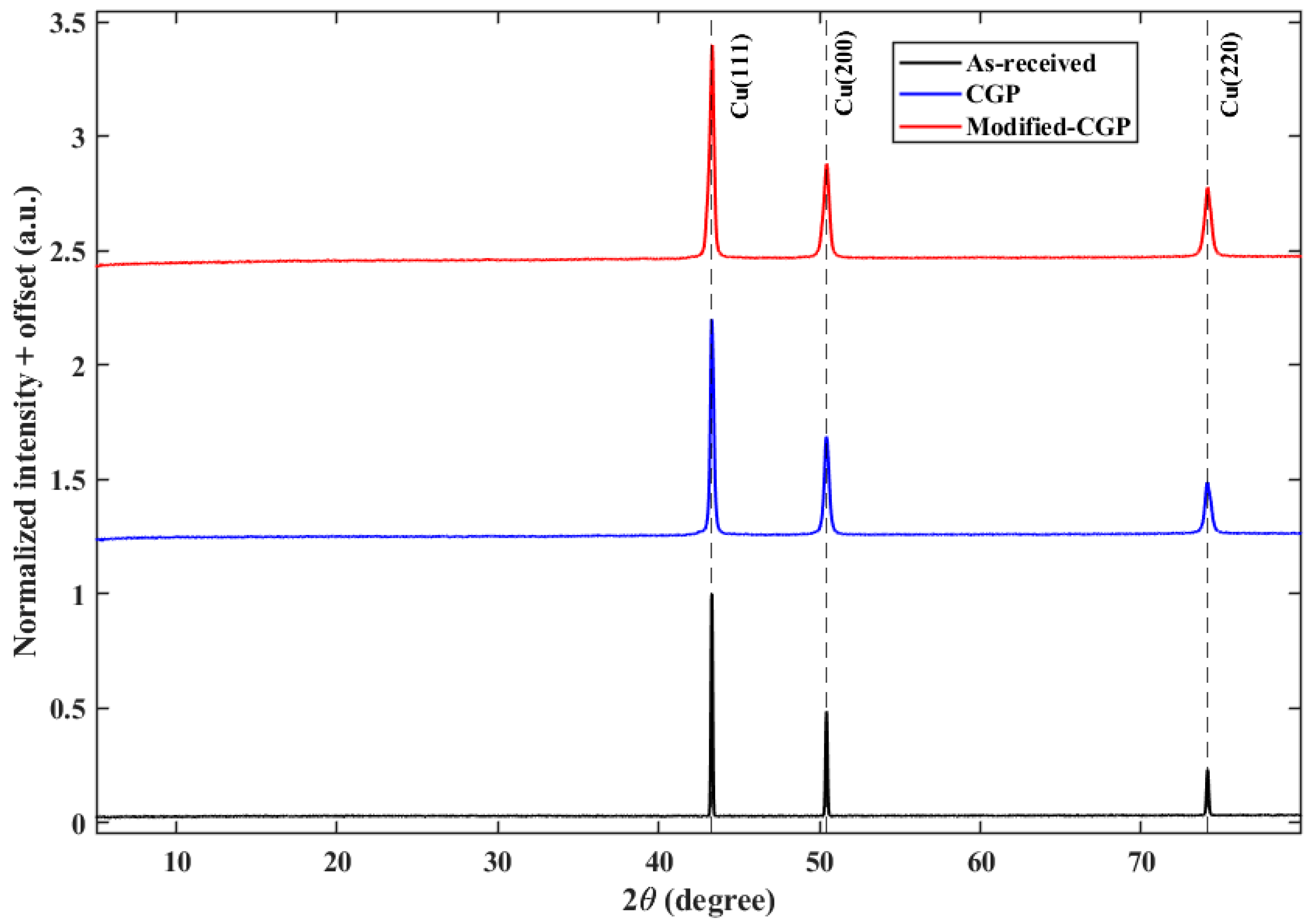
Figure 15 shows the vertically shifted diffraction profiles, which facilitate comparison of the relative peak shapes and intensities. The principal difference among the three conditions is the progressive broadening of the copper reflections from the as-received reference state to CGP and modified CGP. The mean fitted FWHM increased after conventional CGP and reached its maximum value in the modified-CGP condition. This trend indicates that the modified deformation route imposed a more intense crystallographic subdivision and generated a finer defect-bounded structure.
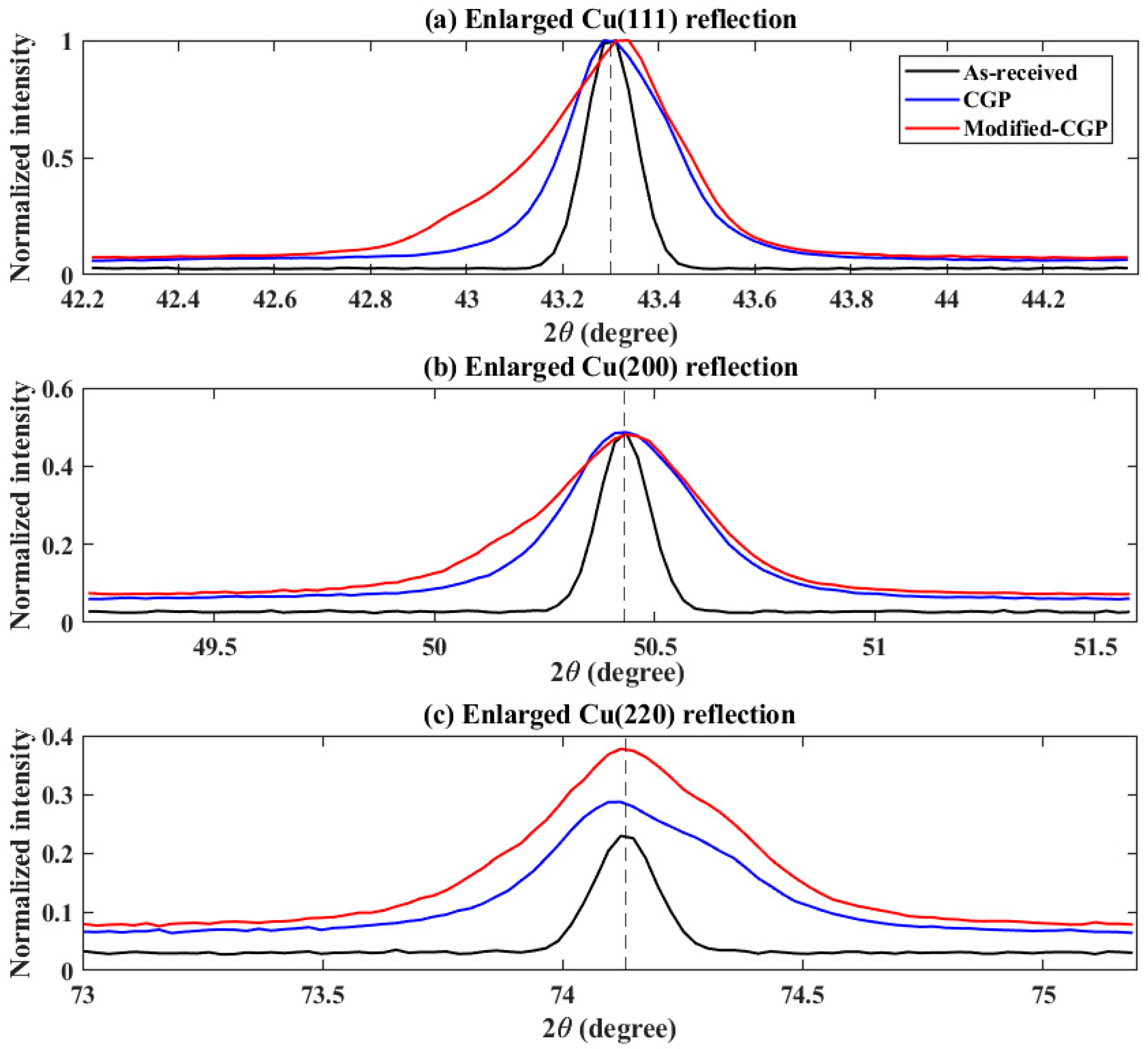
A more detailed comparison is provided in Figure 16, where the Cu(111), Cu(200), and Cu(220) reflections are displayed separately. The enlarged profiles show that the modified-CGP peaks are generally broader than those of the conventional CGP condition. Since diffraction-line broadening is inversely related to coherent diffraction-domain size, the broader peaks indicate a greater degree of crystallographic refinement.
The apparent, instrument-uncalibrated coherent diffraction-domain size was evaluated from the fitted FWHM values using the Scherrer equation introduced in the experimental section [29]. The average apparent coherent-domain size was approximately 27.39 ± 5.99 nm for the CGP sample and 22.75 ± 3.00 nm for the modified-CGP sample; modified CGP therefore reduced the mean coherent-domain size by approximately 17% relative to conventional CGP. These values are presented for comparative purposes only; absolute domain sizes should be interpreted with caution due to the absence of instrumental broadening correction, as noted in Section 2.8. The corresponding comparative defect-density index, defined in the same section, was higher for the modified-CGP condition than for the conventional CGP sample, consistent with a higher density of dislocation cells, subgrain boundaries, and deformation-generated crystallographic defects. This increase provides a crystallographic explanation for the enhanced resistance to dislocation motion in the modified condition.
It is important to distinguish the Scherrer-derived coherent-domain size from the metallographic grain size. The as-received annealed Cu-DHP sample exhibits grains in the micrometre range, whereas the nanometre-scale XRD values correspond to apparent, instrument-uncalibrated coherently diffracting subregions within the deformed microstructure [30]. A single optical grain may contain several dislocation cells, subgrains, and coherent domains. Consequently, the XRD results do not imply that the entire metallographic grain structure was directly reduced to approximately 20–30 nm. Instead, they demonstrate the formation of apparent nanoscale coherent domains and highly subdivided crystallographic regions inside the originally coarse grains. It is emphasised that the term “nanoscale” in this context refers to the XRD-derived apparent coherent domain size, not to a directly measured metallographic grain size. Direct grain-size determination would require electron backscatter diffraction (EBSD) or transmission electron microscopy (TEM).
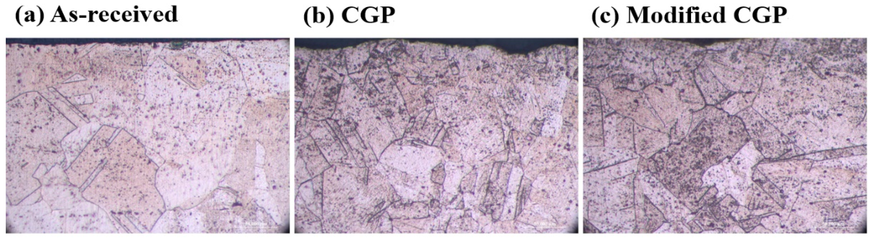
The optical micrographs of the three conditions are compared in Figure 17. Before deformation, the as-received Cu-DHP sample exhibits comparatively coarse, polygonal grains with clearly visible boundaries. Straight intragranular features are also observed in several grains and may be associated with annealing twins, slip traces, or etching contrast. The overall grain dimensions are clearly within the micrometre range, confirming that the initial material is coarse-grained rather than nanocrystalline.
After conventional CGP, the initially polygonal grains become more irregular and distorted. A higher density of intragranular deformation features is visible, indicating that the imposed shear deformation generated extensive slip activity and promoted subdivision of the original grains. Grain boundaries also appear less regular, and several regions exhibit pronounced deformation bands and heterogeneous etching contrast. These observations indicate that conventional CGP initiated substantial grain fragmentation and the formation of a deformation substructure.
The modified-CGP condition exhibits the highest degree of morphological disruption. The grains appear more strongly fragmented, the density of intragranular deformation features is greater, and locally refined regions are more widely distributed. This observation is consistent with the higher XRD peak broadening and smaller coherent-domain size calculated for the modified route. The modified process therefore appears to distribute and accumulate plastic deformation more effectively than the conventional CGP route.
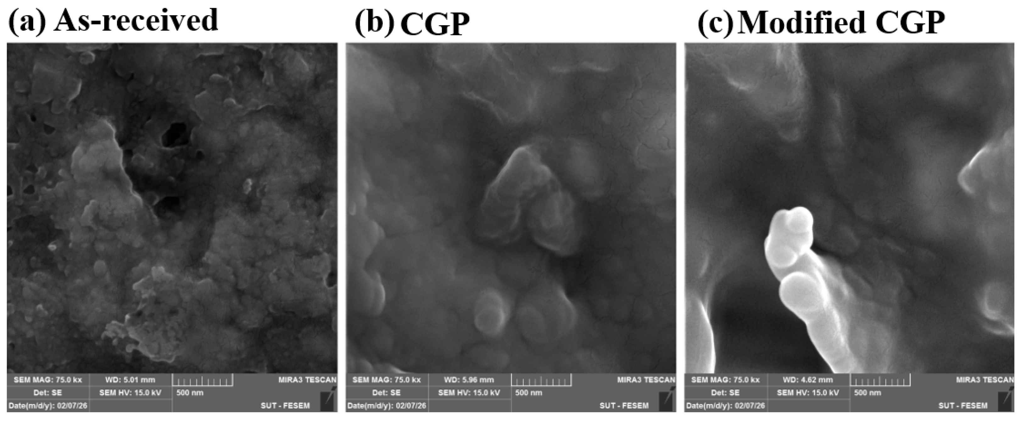
The high-magnification SEM images are shown in Figure 18. These images provide additional information regarding the nanoscale and submicrometre surface morphology. The as-received condition exhibits a comparatively coarse and heterogeneous surface containing irregular protrusions and cavities. After CGP, the surface morphology becomes more compact and displays a denser network of fine deformation-related features. The modified-CGP surface exhibits the most intense local deformation and the finest surface-scale features.
Although several observed SEM features occur on the submicrometre or nanometre scale, the grain boundaries are not sufficiently resolved in the present secondary-electron images to permit a reliable direct measurement of grain size. Therefore, the SEM observations support the development of nanoscale surface features and deformation-induced substructures, but they do not independently confirm that the entire material has become fully nanocrystalline. Taken together, the optical microscopy, SEM, and XRD results describe a multiscale refinement process. The as-received Cu-DHP sample begins with coarse, micrometre-scale grains. Conventional CGP produces grain distortion, deformation bands, sub-grain formation, and fragmentation of the original microstructure. Modified CGP intensifies these effects and generates the smallest coherent diffraction domains and the highest comparative defect-density index. The processed material can therefore be described as a severely fragmented microstructure containing apparent nanoscale coherent domains (as indicated by XRD) and deformation-induced sub-grains. However, it is emphasised that the term “nanoscale” refers to the XRD-derived apparent coherent domain size, not to a directly measured grain size.
The XRD results justify the expression “apparent nanoscale coherent diffraction domains,” because the calculated apparent, instrument-uncalibrated domain sizes are below 100 nm. The optical and SEM observations also demonstrate extensive grain fragmentation and suggest a tendency toward a refined structure. However, a definitive classification of the actual metallographic grain structure as ultrafine-grained (conventionally associated with grain dimensions below approximately 1 µm [1,4]) or fully nanocrystalline (grain dimensions below approximately 100 nm) would require direct grain-boundary mapping by EBSD or TEM. Until such measurements are performed, the microstructure should be described as a severely fragmented structure containing apparent nanoscale coherent domains, rather than as definitively ultrafine-grained or nanocrystalline.
The crystallographic and microstructural trends are also consistent with the measured hardness response. The mean hardness increased from 68.50 ± 2.9 HV in the as-received condition to 107.62 ± 8.5 HV after CGP and 131.38 ± 24.4 HV after modified CGP. The increase is attributed to the combined effects of work hardening, grain and subgrain subdivision, accumulation of crystal defects, and increased resistance to dislocation motion. The modified-CGP condition, which exhibited the smallest apparent coherent-domain size and the most pronounced microstructural fragmentation, also showed the highest average hardness. Overall, the combined observations demonstrate that modified CGP is more effective than conventional CGP in promoting crystallographic subdivision and microstructural refinement. The process retains the FCC copper phase while transforming the initially coarse, micrometre-scale Cu-DHP microstructure into a highly deformed and fragmented structure containing nanoscale coherent domains and fine deformation substructures.

4. Conclusions

An MCGP process was proposed for DHP copper sheet, in which the sharp crest and valley junctions of the conventional 45° trapezoidal die are replaced by two tangent circular arcs (R1 = 1.6 mm at the crest, R2 = 4.8 mm at the valley) while the 45° groove angle, pitch, and die envelope are preserved. The principal findings are as follows:
  • The proposed MCGP die preserves the 45° groove angle, pitch, and overall die envelope of conventional CGP, enabling drop-in compatibility with existing equipment while removing the sharp geometric discontinuities responsible for parasitic bending strain. Analytical estimation confirmed that the conventional CGP die imposes an ideal equivalent strain of 0.577 per shearing stage and approximately 1.16 per complete pass. The MCGP modification introduces only local bending indicators at the crest (ε_eq = 0.456) and valley (ε_eq = 0.247), confirming that the modification redistributes deformation rather than increasing the nominal straining level.
  • Microhardness increased from 68.50 HV in the as-received state to 107.62 HV after conventional CGP and to 131.38 HV after MCGP, the highest of the three conditions and approximately 22% above conventional CGP, reflecting the more effective strain accumulation imposed by the arc-modified die.
  • Uniaxial tension confirmed the same ranking: MCGP raised the yield strength to 281.19 MPa and the ultimate tensile strength to 451.94 MPa (96.4% above the as-received state and 23.8% above conventional CGP). This strengthening was accompanied by the characteristic strength–ductility trade-off of severe plastic deformation, with total elongation reducing from 77.94% to 12.15%.
  • X-ray diffraction revealed progressive peak broadening, with the apparent, instrument-uncalibrated coherent diffraction-domain size decreasing from 27.39 ± 5.99 nm after conventional CGP to 22.75 ± 3.00 nm after MCGP (approximately 17% finer for comparative purposes), together with the highest comparative defect-density index for the modified route. Optical microscopy and scanning electron microscopy independently confirmed the most pronounced grain fragmentation in the MCGP condition. It is emphasised that the XRD values refer to apparent coherent domain sizes, not directly measured grain sizes; direct grain-size determination would require electron backscatter diffraction or transmission electron microscopy.
  • Finite-element simulation of the grooving stage showed that the MCGP die lowers the peak equivalent plastic strain and spreads the deformation along a more continuous through-thickness path at an unchanged nominal pass strain (≈1.16). It is noted that these results are for a single grooving stage; a complete simulation of the full CGP pass (including flattening and sample rotation) would be required for a complete description of the cumulative strain history. By replacing the sharp groove junctions with tangent arcs, the modified die removes the geometric discontinuity responsible for the parasitic bending strain and the characteristic in-plane sinusoidal hardness pattern of conventional CGP.
  • The measured through-thickness hardness inhomogeneity factor nevertheless rose from 7.14% (conventional CGP) to 21.97% (MCGP), indicating that the additional hardening was concentrated in the mid-thickness region. This apparent paradox, a more distributed FEM strain field but higher hardness inhomogeneity, is attributed to: (i) the idealised frictionless contact assumed in the FEM model, whereas residual friction in the experiments introduces additional strain gradients; (ii) the cumulative effect of four stages over a complete CGP pass, where the asymmetry of the MCGP die (R1 ≠ R2) is not fully averaged out by 180° rotation; and (iii) the redistribution, rather than amplification, of the fixed nominal pass strain (≈1.16), which inevitably concentrates deformation in some regions. Full through-thickness uniformity remains an objective for further optimisation of the arc radii, with future work incorporating realistic friction coefficients and parametric FEM studies. The finite-element peak of grooving strain (0.586) matched the analytical value (0.577) to within 1.43%, providing cross-technique validation of the numerical model.
Collectively, these results establish the proposed MCGP process as a drop-in, equipment-compatible modification of conventional CGP that preserves the proven 45° shear kinematics while removing the parasitic bending discontinuity, delivering markedly higher strength (yield up to 281.19 MPa and ultimate tensile strength up to 451.94 MPa) and finer crystallographic refinement at an unchanged nominal pass strain. The mutual consistency across microhardness, tensile testing, and XRD characterisation, all ranking the three conditions in the same order (as-received < conventional CGP < MCGP), substantiate the strengthening and refinement attributed to the arc-modified die. Fully realising the in-plane homogeneity benefit of the smoothed geometry and improving through-thickness uniformity will require further optimisation of the arc radii together with electron backscatter diffraction or transmission electron microscopy characterisation; nonetheless, the present results already demonstrate the promise of the MCGP process for producing more damage-tolerant DHP copper components, with direct potential implications for extending the service life and structural reliability of marine equipment by suppressing strain-localisation sites that initiate premature damage. It is noted that direct seawater corrosion, corrosion fatigue, and thermal cycling tests were not performed in this study; the potential service life benefits are inferred from the well-established literature on the positive effects of grain refinement on corrosion and corrosion-fatigue resistance in copper [18,19]. Future work should include marine environmental tests (seawater corrosion, corrosion fatigue) to validate service life implications, multi-pass processing to confirm the modified die’s homogenising effect over multiple cycles, and experimental verification of reduced surface microcracking and local strain exhaustion.

Author Contributions

M.F.: Conceptualization, methodology, software, and original draft preparation. M.R.D.: Supervision and formal review. K.R.K.: Validation, supervision, and critical review. M.C.: Manuscript writing, validation, project administration and submissions. All authors have read and agreed to the published version of the manuscript.

Funding

The authors received no financial support for the research, authorship, or publication of this article.

Data Availability Statement

The datasets generated and analysed during the current study are not publicly available due to privacy restrictions associated with an ongoing larger project. However, data are available from the corresponding author upon reasonable request.

Acknowledgments

This paper was supported by the RUDN University Strategic Academic Leadership Program.

Conflicts of Interest

The authors declare that there are no known competing financial interests or personal relationships that could have appeared to influence the work reported in this paper.

References

  1. Valiev, R.Z.; Islamgaliev, R.K.; Alexandrov, I.V. Bulk Nanostructured Materials from Severe Plastic Deformation. Prog. Mater. Sci. 2000, 45, 103–189. [Google Scholar] [CrossRef]
  2. Azushima, A.; Kopp, R.; Korhonen, A.; Yang, D.Y.; Micari, F.; Lahoti, G.D.; Groche, P.; Yanagimoto, J.; Tsuji, N.; Rosochowski, A.; et al. Severe Plastic Deformation (SPD) Processes for Metals. CIRP Ann. Manuf. Technol. 2008, 57, 716–735. [Google Scholar] [CrossRef]
  3. Gupta, A.K.; Maddukuri, T.S.; Singh, S.K. Constrained Groove Pressing for Sheet Metal Processing. Prog. Mater. Sci. 2016, 84, 403–462. [Google Scholar] [CrossRef]
  4. Valiev, R.Z.; Estrin, Y.; Horita, Z.; Langdon, T.G.; Zehetbauer, M.J.; Zhu, Y.T. Producing Bulk Ultrafine-Grained Materials by Severe Plastic Deformation. JOM 2006, 58, 33–39. [Google Scholar] [CrossRef]
  5. Shin, D.H.; Park, J.-J.; Kim, Y.-S.; Park, K.-T. Constrained Groove Pressing and Its Application to Grain Refinement of Aluminum. Mater. Sci. Eng. A 2002, 328, 98–103. [Google Scholar] [CrossRef]
  6. Saito, Y.; Utsunomiya, H.; Tsuji, N.; Sakai, T. Novel Ultra-High Straining Process for Bulk Materials, Development of the Accumulative Roll-Bonding (ARB) Process. Acta Mater. 1999, 47, 579–583. [Google Scholar] [CrossRef]
  7. Kumar, S. Developing Methods of Constrained Groove Pressing Technique: A Review. Proc. Inst. Mech. Eng. Part L J. Mater. Des. Appl. 2023, 237, 1319–1346. [Google Scholar] [CrossRef]
  8. Yadav, P.C.; Sinhal, A.; Sahu, S.; Roy, A.; Shekhar, S. Microstructural Inhomogeneity in Constrained Groove Pressed Cu-Zn Alloy Sheet. J. Mater. Eng. Perform. 2016, 25, 2604–2614. [Google Scholar] [CrossRef]
  9. Wang, Z.-S.; Guan, Y.-J.; Liang, P. Deformation Efficiency, Homogeneity, and Electrical Resistivity of Pure Copper Processed by Constrained Groove Pressing. Rare Met. 2014, 33, 287–292. [Google Scholar] [CrossRef]
  10. Rafizadeh, E.; Mani, A.; Kazeminezhad, M. The Effects of Intermediate and Post-Annealing Phenomena on the Mechanical Properties and Microstructure of Constrained Groove Pressed Copper Sheet. Mater. Sci. Eng. A 2009, 515, 162–168. [Google Scholar] [CrossRef]
  11. Borhani, M.; Djavanroodi, F. Rubber Pad-Constrained Groove Pressing Process: Experimental and Finite Element Investigation. Mater. Sci. Eng. A 2012, 546, 1–7. [Google Scholar] [CrossRef]
  12. Sawalkar, S.; Field, D.P. Constrained Groove Uniform Pressing Process for Achieving Homogeneously Improved Properties in Copper. Mater. Sci. Eng. A 2024, 899, 146417. [Google Scholar] [CrossRef]
  13. Torkestani, A.; Dashtbayazi, M.R. A New Method for Severe Plastic Deformation of the Copper Sheets. Mater. Sci. Eng. A 2018, 737, 236–244. [Google Scholar] [CrossRef]
  14. Kaykha, M.M.; Dashtbayazi, M.R. An Improvement in Constrained Studded Pressing for Producing Ultra-Fine-Grained Copper Sheet. Metals 2022, 12, 193. [Google Scholar] [CrossRef]
  15. Hosseini Faregh, S.S.; Raiszadeh, R.; Dashtbayazi, M.R. Pure Copper Sheets Processed by Constrained Studded Pressing: The Effect of Die Angle. J. Mater. Eng. Perform. 2024, 33, 3262–3272. [Google Scholar] [CrossRef]
  16. Hosseini Faregh, S.S.; Raiszadeh, R.; Dashtbayazi, M.R. Comparing the Microstructure and Mechanical Properties of Pure Copper Sheets Subjected to Different Types of Constrained Dies Pressing. Trans. Indian Inst. Met. 2024, 77, 727–735. [Google Scholar] [CrossRef]
  17. ASTM B75/B75M; Standard Specification for Seamless Copper Tube. ASTM International: West Conshohocken, PA, USA, 2022. [CrossRef]
  18. Yamasaki, T.; Miyamoto, H.; Mimaki, T.; Vinogradov, A.; Hashimoto, S. Corrosion Fatigue of Ultra-Fine Grain Copper Fabricated by Severe Plastic Deformation. In Ultrafine Grained Materials II; Zhu, Y.T., Langdon, T.G., Mishra, R.S., Semiatin, S.L., Saran, M.J., Lowe, T.C., Eds.; TMS: Warrendale, PA, USA, 2002; pp. 457–466. [Google Scholar]
  19. Miyamoto, H. Corrosion of Ultrafine Grained Materials by Severe Plastic Deformation, an Overview. Mater. Trans. 2016, 57, 559–572. [Google Scholar] [CrossRef]
  20. Chen, F.; Tan, B.; Tang, H.; Zhang, H.; Luo, Y.; Xiao, X.; Liu, Y.; Lu, N. An interpretable random forest surrogate for rapid SIF prediction and fatigue life assessment of double-sided U-rib welds in orthotropic steel decks. Eng. Fail. Anal. 2026, 187, 110582. [Google Scholar] [CrossRef]
  21. Zhang, H.; Deng, Y.; Chen, F.; Luo, Y.; Xiao, X.; Lu, N.; Liu, Y.; Deng, Y. Fatigue Life Prediction for Orthotropic Steel Bridge Deck Welds Using a Gaussian Variational Bayes Network and Small Sample Experimental Data. Reliab. Eng. Syst. Saf. 2025, 264, 111406. [Google Scholar] [CrossRef]
  22. Zhang, H.; Zhao, L.; Chen, F.; Luo, Y.; Xiao, X.; Liu, Y.; Deng, Y. A machine learning and multi-source authentic data-driven framework for accurate fatigue life prediction of welds in existing steel bridge decks. Thin-Walled Struct. 2026, 222, 114559. [Google Scholar] [CrossRef]
  23. Tripathi, N.; Setia, P.; Sawalkar, S.; Mondal, K.; Shekhar, S. Constrained Constant Radius Pressing (CCRP) Process to Improve Mechanical Properties and Microstructural Homogeneity of Pure Copper Sheet. Mater. Today Commun. 2023, 38, 107695. [Google Scholar] [CrossRef]
  24. Taylor, S.; Masters, I.; Li, Z.; Wang, J.; Li, J.; Siddle, D.; Beladi, H. Direct Observation via In Situ Heated Stage EBSD Analysis of Recrystallization of Phosphorous Deoxidised Copper in Unstrained and Strained Conditions. Met. Mater. Int. 2020, 26, 1030–1035. [Google Scholar] [CrossRef]
  25. Hill, R. The Mathematical Theory of Plasticity; Clarendon Press: Oxford, UK, 1950. [Google Scholar]
  26. ASTM E384-22; Standard Test Method for Microindentation Hardness of Materials. ASTM International: West Conshohocken, PA, USA, 2022. [CrossRef]
  27. ASTM E8/E8M-22; Standard Test Methods for Tension Testing of Metallic Materials. ASTM International: West Conshohocken, PA, USA, 2022. [CrossRef]
  28. Kumar, S.; Suwas, S.; Chakkingal, U. Numerical Study of Constrained Groove Pressing to Produce Ultra-Fine-Grained Sheet Materials. In Proceedings of the 6th International & 27th All India Manufacturing Technology, Design and Research Conference (AIMTDR 2016), Pune, India, 16–18 December 2016; pp. 553–558. [Google Scholar]
  29. Cullity, B.D.; Stock, S.R. Elements of X-Ray Diffraction, 3rd ed.; Prentice Hall: Upper Saddle River, NJ, USA, 2001. [Google Scholar]
  30. Ungár, T. Microstructural Parameters from X-ray Diffraction Peak Broadening. Scr. Mater. 2004, 51, 777–781. [Google Scholar] [CrossRef]
  31. Taylor, G.I. The Mechanism of Plastic Deformation of Crystals. Part I., Theoretical. Proc. R. Soc. Lond. A 1934, 145, 362–387. [Google Scholar] [CrossRef]
Figure 1. Schematic of one complete pass of the conventional CGP process: (a) sheet specimen; (b) first pressing; (c) first flattening with the flat dies; (d) 180° in-plane rotation of the specimen; (e) second grooving; and (f) the resulting nominally uniform effective-strain distribution after one complete pass.
Jmse 14 01455 g001
Figure 2. Manufactured modified-CGP (MCGP) die showing the locations of the two tangent arcs R1 and R2: (a) lower die with the grooving direction and the longitudinal (LT) and transverse (TD) directions indicated; (b) upper die with the LT and TD directions indicated; (c) close-up of the groove cross-section showing the crest arc R1 and the valley arc R2, their respective centres, and the common tangent point T.
Jmse 14 01455 g002
Figure 3. Fabricated dies mounted in the hydraulic press: (a) modified-CGP (MCGP) dies, upper die, copper plate, lower die, and holder; (b) conventional CGP dies, upper die, copper plate, lower die, and holder; (c) flattening dies, upper die, grooved copper plate, and lower die.
Jmse 14 01455 g003
Figure 4. Tensile specimens prepared according to ASTM E8/E8M: (a) geometry and dimensions of the specimens, and representative machined specimens in the (b) as-received, (c) CGP-processed, and (d) modified-CGP-processed conditions. All specimens were extracted from the central region of the processed sheets along the transverse direction.
Jmse 14 01455 g004
Figure 5. Mesh and element types adopted for the finite-element models: (a) conventional CGP; (b) modified CGP (MCGP).
Jmse 14 01455 g005
Figure 6. Regional Vickers microhardness measured in the upper, middle, and lower regions of the as-received, conventional CGP, and modified CGP specimens. Error bars denote the standard deviation of six indentations per region (n = 6).
Jmse 14 01455 g006
Figure 7. Average Vickers microhardness of the as-received, conventional CGP, and modified CGP specimens. Error bars denote the standard deviation of all eighteen indentations per specimen (n = 18).
Jmse 14 01455 g007
Figure 8. Overall and through-thickness hardness inhomogeneity factors (IF) of the as-received, conventional CGP, and modified CGP specimens. IF values are calculated from Equations (19)–(21) in Section 3.1.
Jmse 14 01455 g008
Figure 9. Longitudinal Vickers microhardness profiles measured in the upper (Top), middle (Middle), and lower (Bottom) regions: (a) as-received, (b) conventional CGP, and (c) modified CGP. Measurements were taken at 0.5 mm intervals along the longitudinal direction.
Jmse 14 01455 g009
Figure 10. Average engineering stress–strain curves of the as-received, conventional CGP, and modified CGP specimens. Each curve represents the mean response obtained from three independent tensile tests.
Jmse 14 01455 g010
Figure 11. Tensile properties of the as-received, conventional CGP, and modified CGP specimens: (a) yield strength, (b) ultimate tensile strength, and (c) total elongation. Values are presented as mean ± standard deviation from three independent tensile tests (n = 3). All error bars represent the standard deviation of three independent measurements.
Jmse 14 01455 g011
Figure 12. Finite-element PEEQ (equivalent plastic strain) distribution and the corresponding experimental grooved specimens for the grooving stage: (a) FE PEEQ contour of conventional CGP, with the zoomed measurement region and the 3 mm sheet thickness indicated; (b) experimental conventional-CGP specimen showing the longitudinal (LT) and transverse (TD) directions, with lubricant residue retained to indicate the frictionless contact condition; (c) FE PEEQ contour of the modified CGP die, with the two tangent-arc radii (R1 = 1.6 mm at the crest and R2 = 4.8 mm at the valley) indicated; (d) experimental modified-CGP specimen in the LT and TD directions after cleaning.
Jmse 14 01455 g012
Figure 13. Local through-thickness equivalent plastic strain (PEEQ) profiles extracted from the finite-element model: (left) conventional CGP, showing the symmetric profile that rises from ≈ 0.384 at the sheet surfaces to a numerical peak of 0.586 at the mid-thickness; (right) modified CGP, showing the asymmetric profile along the 3 mm path from R1 to R2, with the numerical endpoints (0.195 at R2, 0.395 at R1) and the corresponding analytical bending indicators (0.247 at R2, 0.456 at R1) marked at each radius.
Jmse 14 01455 g013
Figure 14. Normalized XRD patterns of the as-received Cu-DHP reference profile, CGP-processed copper, and modified-CGP-processed copper over the full investigated 2θ range. Values are presented as mean ± standard deviation from three independent tensile tests (n = 3).
Jmse 14 01455 g014
Figure 15. Stacked XRD patterns of the as-received/reference, CGP, and modified-CGP conditions. Vertical offsets were applied only for visual clarity.
Jmse 14 01455 g015
Figure 16. Enlarged diffraction profiles around the Cu(111), Cu(200), and Cu(220) reflections, showing the progressive increase in peak broadening after CGP and modified CGP processing.
Jmse 14 01455 g016
Figure 17. Optical micrographs of Cu-DHP copper in the (a) as-received, (b) CGP, and (c) modified CGP-processed conditions. The scale bar is 50 µm.
Jmse 14 01455 g017
Figure 18. High-magnification (500 nm) SEM images of Cu-DHP copper in the (a) as-received, (b) CGP-processed, and (c) modified-CGP-processed conditions. The observed features are predominantly topographic in nature and are associated with deformation-induced surface morphology and substructures formed during severe plastic deformation.
Jmse 14 01455 g018
Table 1. Die-profile parameters of the conventional CGP and the proposed MCGP dies.
ParameterConventional CGPProposed MCGP
Groove angle45°45° (preserved)
Crest junctionSharp cornerTangent arc, R1 = 1.6 mm
Valley junctionSharp cornerTangent arc, R2 = 4.8 mm
Radius ratio, λ = R2/R13
Junction geometryGeometric discontinuityC1 continuous (tangent continuity) with graded curvature
Die materialCK60 tool steelCK60 tool steel
Press capacity1000 kN1000 kN
Crest curvature, κ1∞ (discontinuous)0.625 mm−1
Valley curvature, κ2∞ (discontinuous)0.208 mm−1
Deformation mechanismConcentrated shearDistributed, graded-curvature bending
Comparison with CCRP [24]Dual-radius (λ ≈ 3) vs. single-radius (λ = 1)
Table 2. Analytical strain values for the conventional CGP die and local curvature-based bending indicators for the proposed MCGP die. It is emphasised that the local bending indicators in the MCGP rows are local analytical estimates of bending severity at the curved junctions; they are not uniform strain values for the entire specimen and should not be added to the nominal shear strain of 1.16.
Process/Deformation ZoneGeometryCurvature, κ   mm 1 Tangential Strain, ε θ Effective Strain Per StagePass-level Index (×4)Physical Interpretation
Conventional CGPφ = 45°; groove depth = sheet thickness = 3 mm (sharp corner)0.5771.160Nominal ideal shear strain (γ-based)
MCGP-crest junctionR1 = 1.6 mm0.6250.3950.4561.824Local bending severity at the crest
MCGP-valley junctionR2 = 4.8 mm0.2080.2140.2470.988Local bending severity at the valley
MCGP-dual-radius indexR1 = 1.6 mm; R2 = 4.8 mm0.625/0.2080.6090.7032.812Upper-bound local analytical indicator (crest + valley); not a uniform sheet strain and should not be interpreted as the cumulative strain for the entire specimen
Disclaimer/Publisher’s Note: The statements, opinions and data contained in all publications are solely those of the individual author(s) and contributor(s) and not of MDPI and/or the editor(s). MDPI and/or the editor(s) disclaim responsibility for any injury to people or property resulting from any ideas, methods, instructions or products referred to in the content.