Article

Theoretical Analysis and Optimal Design of Underwater Towed Body Dynamic Stability

1
School of Mathematical Science, Nankai University, Shanghai 200127, China
2
Ocean Institute, Northwestern Polytechnical University, Xi’an 710072, China
*
Author to whom correspondence should be addressed.
J. Mar. Sci. Eng. 2026, 14(14), 1342; https://doi.org/10.3390/jmse14141342
Submission received: 17 May 2026 / Revised: 17 June 2026 / Accepted: 2 July 2026 / Published: 22 July 2026
(This article belongs to the Section Ocean Engineering)

Abstract

This study presents the analysis of towed stability and the optimization design method for an underwater towed body, aiming to design a towing system with high stability, good hydrodynamic performance and a high degree of safety and reliability. By proposing analytical models for both the static and dynamic behavior of the towing system, the influence of the structural characteristics on the motion of the towed body were determined. The Computational Fluid Dynamics (CFD) method was employed to conduct hydrodynamic numerical simulations of the towed body, obtaining precise hydrodynamic coefficients. The optimization design of the towed body’s center of gravity and cable connecting point position was carried out. The simulation results systematically revealed the influence of towing speed and cable length on the dynamic behavior of the towed body. With the speed increasing from 4 kN to 20 kN the depth of the towed body reduces from 277.0 m to 90.6 m, the tension of the cable inreases from 11.5 kN to 171.85 kN. At a towing speed of 20 kN, the optimized towed body stay at an averaged pitch angle of 6.82 ° with very small roll angles. This research provides theoretical and numerical analyzing approach for the design of high-performance underwater towed bodies.

1. Introduction

Rapid economic development has accelerated the consumption of land-based resources, while the deep ocean still contains abundant natural gas, oil and various rare metals essential for industrial development. As human demands for marine resource development, geological exploration, disaster warning and underwater target monitoring continue to increase, developing efficient and accurate marine exploration technologies has become increasingly critical. Underwater towing systems, as core equipment for modern ocean investigation and exploration, are widely used in tasks such as hydrological surveys, geological exploration and acoustic detection. A typical underwater towing system consists of a tow cable and a towed body, which carries various sensors for data collection. Compared with autonomous underwater vehicles that house sensors internally, towed bodies offer advantages such as reduced space constraints for measurement equipment, easier payload replacement, and lower self-noise interference, making them particularly suitable for fine-scale and rapidly varying deep-sea observations [1,2]. Holmes et al. [1] first demonstrated the feasibility of deploying a hydrophone line array via a towed platform for ocean acoustic measurements, establishing a foundation for towed sensing systems. Pallayil et al. [2] further advanced this concept by developing a low-profile hydrophone array system for towed deployment, testing its seabed characterization and marine mammal detection capabilities. In the context of underwater security and target detection, Palomeras et al. [3] applied forward-looking sonar data to automatic target recognition, demonstrating the operational versatility of towed sensing platforms. Beyond acoustic applications, Savini et al. [4] used a towing system to image shallow gas migration pathways in a mud-volcano province, showcasing the capability of towed bodies in geological surveys.
However, existing research on underwater towed body technology, hydrodynamic issues of underwater towing systems, and position and attitude control of towed bodies still has some shortcomings. When underwater towed bodies work in complex and harsh underwater environments, factors such as towing speed, propeller wake of the towing vessel, and the vessel’s heaving motion in waves can interfere with the position and attitude of the towed body. These interference factors greatly reduce the efficiency of information exchange between the sensors carried by the towed body and the underwater environment. The towing system has strong coupling and highly nonlinear characteristics, with complex dynamic responses among the tow cable and the towed body. The dynamic coupling between the flexible tow cable and the rigid towed body is a central challenge in understanding and predicting the motion behavior of the entire system. In the literature on cable dynamics, substantial progress has been made in modeling the behavior of towed cables under various conditions. Leech and Tabarrok [5] provided a closed-form solution for the steady-state geometry of a towed cable under two-dimensional conditions, which remains a benchmark for cable configuration analysis. Ablow and Schechter [6] developed a finite difference method for numerical simulation of undersea cable dynamics, which has been widely adopted in subsequent studies of towing systems. Huang [7] contributed a three-dimensional dynamic analysis method for marine cables, enabling more realistic simulations of towing systems operating in oblique current conditions. Buckham et al. [8] advanced the field by developing a finite element cable model specifically designed for low-tension dynamics simulation, which is particularly relevant to deep-sea towing applications where cable tension can vary significantly. Xu and Zou [9] proposed a flexible segment model that optimizes the dynamic calculation of underwater moving slender bodies, offering improved computational efficiency for long-cable towing systems. Despite of these advances in cable modeling, the coupled dynamics of the entire towing system—including the towed body itself—remain insufficiently understood, particularly under transient operating conditions. How to ensure the stability and motion control flexibility of the underwater towed body in complex and changeable marine environments to enable efficient ocean observation missions is a problem that researchers and engineers must face.
Researchers have conducted extensive studies on underwater towing systems, particularly in terms of hydrodynamic characteristics, motion control, and system optimization, achieving significant progress. In the area of hydrodynamic characteristics and modeling, researchers have deeply investigated towed body shapes, cable configuration, and system coupling dynamics through combined methods of Computational Fluid Dynamics (CFD) simulation, model testing, and theoretical analysis. Park and Kim [10] developed a comprehensive dynamics model of a towing system consisting of a towfish towed by a cable, providing quantitative insights into the coupled motion between the cable and the towed body under various sea states. Wu et al. [11] conducted numerical investigations on underwater towing system dynamics using a novel hydrodynamic model that accounts for both cable and towed body nonlinearities, advancing the understanding of cable-body interactions and their influence on towed body stability. The hydrodynamic performance of the towed body itself is a critical factor determining overall system behavior. The drag and lift characteristics of the towed body shape directly affect both the steady-state towing attitude and the dynamic response to external disturbances. Various numerical methods have been employed to predict these hydrodynamic coefficients, with CFD emerging as a powerful tool for detailed flow field analysis around complex towed body geometries. In the area of position and attitude control strategies for towed bodies, research has shifted from traditional PID control to advanced algorithms such as adaptive control, robust control, and model predictive control (MPC) to address attitude stabilization and trajectory tracking problems under complex sea conditions. Teixeira et al. [12] proposed a nonlinear adaptive control method for an underwater towed vehicle, combining a nonlinear observer with backstepping control to effectively suppress depth and pitch angle oscillations in wave environments. Londhe et al. [13] developed an uncertainty and disturbance estimator-based sliding mode control approach, enhancing robustness against external disturbances and parametric uncertainties without requiring an accurate dynamic model. Gong et al. [14] designed a dual closed-loop MPC scheme for trajectory tracking under uncertain dynamics, achieving superior performance compared to traditional single-loop approaches. In addition to these general control frameworks, several studies have addressed the specific challenges of towed body control. Kostenko et al. [15] developed a combined motion control strategy using a polynomial regression model of cable tension to provide dynamic feedforward compensation, ensuring depth stability during towing operations. Yamaguchi et al. [16] investigated the motion control of a towed vehicle with a long cable, employing a characteristic function method to simplify the cable dynamics and implementing LQI control for depth changing maneuvers. Liu et al. [17] proposed a finite-time fuzzy adaptive control method that simultaneously addresses tracking and pitch control of an underwater towed vehicle with multiple control surfaces, demonstrating improved transient response. Ferri et al. [18] developed a non-myopic receding horizon control strategy for target tracking using a towed array system, incorporating the uncertainty of acoustic measurements into the decision-making framework. In system engineering design and optimization, modular and intelligent design concepts have been introduced, aiming to enhance mission adaptability and reliability. Related research focuses on multidisciplinary design optimization (MDO) methods for underwater systems. Chen et al. [19] applied a gradient-based MDO approach to optimize the overall performance of an underwater vehicle, considering hydrodynamic and structural constraints simultaneously. Bidoki et al. [20] proposed a new MDO framework that integrates system-level and tactic-level design for improved operational efficiency. Liu et al. [21] combined CFD simulations with approximation models to perform multi-objective MDO for an underwater vehicle, demonstrating the effectiveness of this approach in balancing conflicting design objectives such as drag reduction and structural integrity. Alam et al. [22] adopted an evolutionary approach for underwater vehicle design, using NSGA-II and IDEA algorithms to optimize both external dimensions and internal compartment layout simultaneously. Within the context of towed body design specifically, the optimization of the center of gravity and tow point positions has been identified as a critical factor governing both static and dynamic stability, yet systematic parametric studies covering the full range of operational speeds remain limited.
Despite of these advances, challenges remain in towed body design when facing ever-increasing demands for ocean exploration. In particular, the optimization of the center of gravity and tow point positions—two critical parameters that govern both static and dynamic stability—has not been systematically addressed for water-droplet-shaped towed bodies across the full range of operational speeds. The interplay between these two parameters and their coupled effects on towing attitude, depth keeping, and cable tension characteristics requires further investigation. Therefore, this study aims to develop an underwater towed body with high stability, good hydrodynamic performance and high safety and reliability through a systematic design process. This includes theoretical dynamic analysis of the towed body, low-drag streamlined shape design, hydrodynamic simulation using CFD, and towing attitude simulation using the professional software OrcaFlex, to ensure that key indicators such as trim and roll meet stability standards, thereby satisfying the urgent demand for high precision and high reliability in ocean acoustic exploration. The novelty of this work lies in the parametric optimization of center of gravity and tow point positions using coupled CFD-OrcaFlex simulations, providing quantitative design guidelines that can be directly applied to engineering practice.

2. Towing Dynamics Analysis

2.1. Orientation in Static Water and Restoring Moment Analysis

When designing the towed body, acoustic performance, dimensions, weight and towing stability must be considered comprehensively. After preliminary design, the cable connecting point (CCP) position must be determined, and the towed body’s gravity, buoyancy and positions of the center of gravity (CG), the center of buoyancy (CB) and the center of hydrodynamic force (CF) must be calculated. When the towed body is statically suspended in water, it is subjected to three forces: gravity (G), buoyancy (B) and cable tension (T) at CCP. CB is located at the structural centroid of the towed body, while CG and CCP are adjustable. Assuming the towed body has zero heel and zero trim, a fixed coordinate system is established with CCP as the origin: the x-axis points toward the bow, the y-axis points to port, and the z-axis points vertically upward.

2.1.1. Orientation in Static Water

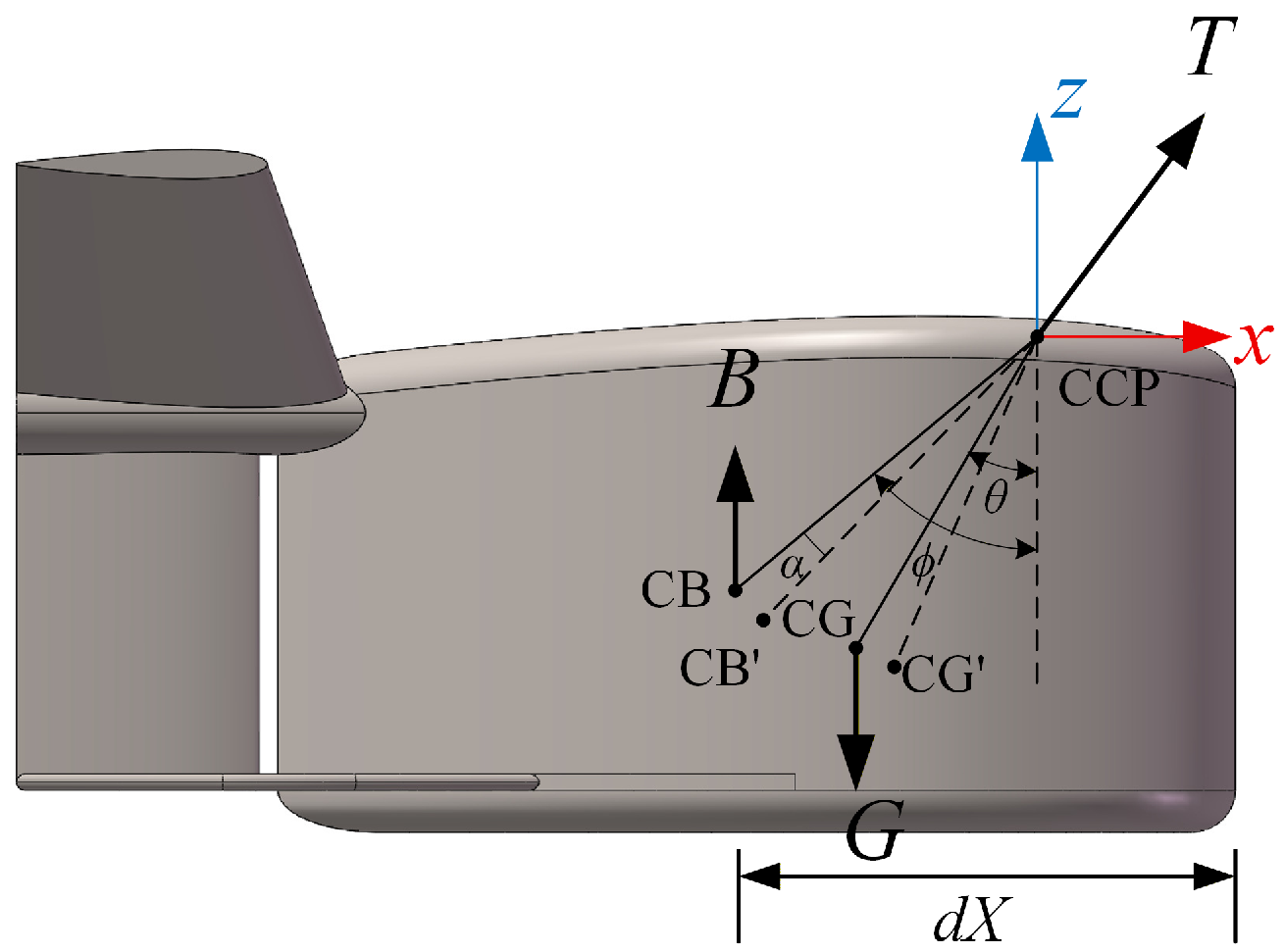
In the fixed coordinate system with the origin at CCP, let the coordinates of CG be ( a , b , c ) and CB be ( d , e , f ) . Projecting the forces onto the mid-longitudinal plane, then the distance from the projection of CG to the projection of CCP is defined as r 1 = a 2 + c 2 and the distance from the projection of CB to the projection of CCP is defined as r 2 = d 2 + f 2 , the static equilibrium is shown in Figure 1.
If the towed body’s longitudinal inclination angle is 0, from moment equilibrium:
G r 1 sin θ = B r 2 sin ϕ
where G is gravity; B is buoyancy; θ is the angle between the line connecting CCP and CG and the negative z-direction; ϕ is the angle between the line connecting CCP and CB and the negative z-direction.
Then the horizontal distance between CG and CB is:
| a d | = ( G B ) | d | G
If CCP moves toward the bow, the towed body assumes a bow-up orientation in static water; conversely, if CCP moves toward the stern, the towed body assumes a bow-down orientation. Let the distance from CB to the leading edge of the towed body be d X . Then the horizontal distance between CCP and CB | d | < d X , and the horizontal distance between CG and CB is | a d | < ( G B ) d X G . When the towed body pitches up by angle α to reach moment equilibrium, CB moves to CB′, CG moves to CG′.
From moment equilibrium:
G r 1 sin ( θ α ) = B r 2 sin ( ϕ α )
Solving for α :
α = arctan G | a | B | d | G | c | B | f |
From Equation (4), the lower the center of gravity CG and the higher the center of buoyancy CB, the smaller the static pitch-up angle of the towed body α .
To ensure good roll stability, the towed body structure is generally designed to be symmetric about the mid-longitudinal plane, so the heel angle in static water can be approximated as 0.

2.1.2. Static Restoring Moment

If a static towed body in water is given an initial disturbance causing a pitch-up angle α , the resulting static restoring moment after the disturbance is removed is:
L = B r 2 sin ( ϕ α ) G r 1 sin ( θ α )
This can be derived as:
L = ( G c B f ) sin α
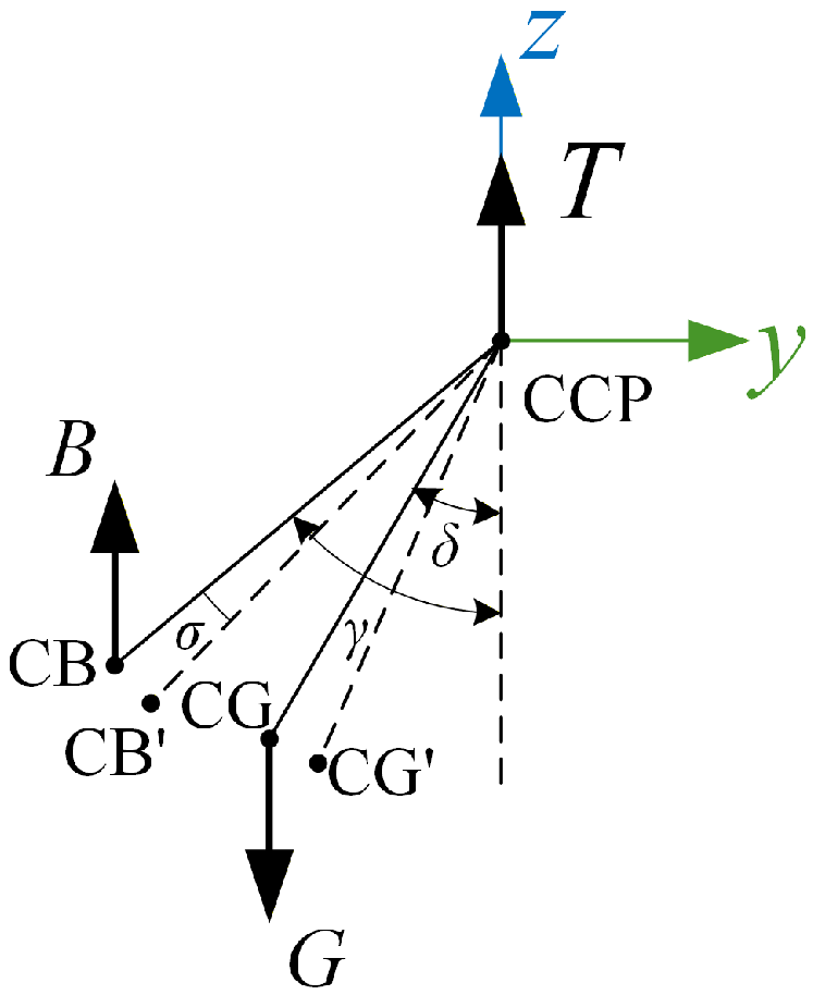
Projecting the forces onto the cross-sectional plane from aft to forward, the static force distribution is shown in Figure 2.
The distance from the projection of CG to the projection of CCP is defined as r 3 = b 2 + c 2 , and the distance from the projection of CB to the projection of CCP is defined as r 4 = e 2 + f 2 . If a static towed body in water is given an initial disturbance causing a right-heel angle σ , the resulting static restoring moment after the disturbance is removed is:
H = B r 4 sin ( γ σ ) G r 3 sin ( δ σ )
where δ is the angle between the line connecting CCP and CG and the negative z-direction; γ is the angle between the line connecting CCP and CB and the negative z-direction.
This can be derived as:
H = ( G c B f ) sin σ
From Equations (6) and (8), the lower the center of gravity CG, the higher the center of buoyancy CB and the greater the net weight, the larger the restoring moment and the higher the stability when statically suspended.

2.2. Hydrodynamic Stability Analysis

When the towed body experiences orientation deviation due to external disturbances (e.g., currents, vessel motion), generating an additional angle of attack or sideslip angle, the static restoring moment provides initial stability, promoting recovery to the equilibrium orientation. However, during dynamic towing, the forces on the towed body include not only gravity (G), buoyancy (B) and cable tension (T), but also hydrodynamic forces (F) related to towing speed. Therefore, whether the towed body can ultimately maintain stability during towing also depends on the characteristics of the hydrodynamic moment: if the hydrodynamic moment is a restoring moment, stability is enhanced; if it is a capsizing moment, instability may occur.

2.2.1. Longitudinal Dynamic Stability Analysis

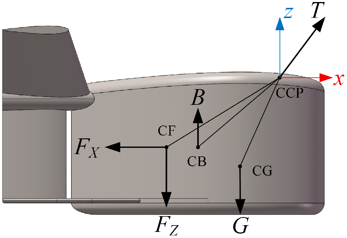
Figure 3 shows the force distribution and moment action on the towed body in the vertical plane.
The total hydrodynamic force F is decomposed into horizontal drag F x and vertical lift F z . Let the coordinates of the center of hydrodynamic force (CF) be ( l , m , n ) . If the longitudinal inclination angle of the towed body is 0 during towing, from moment equilibrium:
G | a | B | d | + F z | l | F x | n | = 0
The relative position of CF with respect to CCP is a key factor affecting the motion stability of the towed body. In the vertical direction, due to structural layout and other performance constraints, CCP is usually arranged above CF. In this case, regardless of the horizontal relative position, the drag F x always creates a continuous bow-down moment, causing the bow to dive. In the horizontal direction, the fore-aft relationship directly affects the ability to resist orientation disturbances: if CF is behind CCP, the moment generated by lift F z can resist the bow-down tendency caused by disturbances, forming a restoring moment and enhancing orientation stability; conversely, if CF is ahead of CCP, the moment generated by lift F z increases the bow-down angle caused by disturbances, exacerbating trim disturbances and adversely affecting stability.
Therefore, the towed body should be designed with a low-drag shape to reduce drag F x while reasonably increasing the projected area of the tail section in the horizontal plane to increase lift F z . Besides, the vertical distance between CF and CCP should be reduced to decrease the bow-down moment caused by drag F x , while the horizontal distance between CF and CCP should be appropriately increased to enhance the trim restoring moment generated by lift F z .

2.2.2. Horizontal Dynamic Stability Analysis

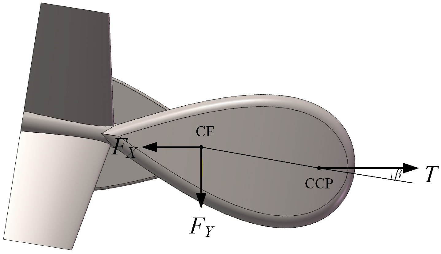
The dynamic analysis of the towed body in the horizontal plane is shown in Figure 4.
Assume that after a disturbance, the towed body develops a yaw angle β (positive for right yaw, negative for left yaw). The hydrodynamic forces F on the towed body include drag F x opposite to the velocity direction and yaw force F y perpendicular to the velocity direction. The moment produced by F about the CCP is:
N = F x | l | sin β + F y | l | cos β
From Equation (10), if CF is behind CCP, both the moment due to lift F y and that due to drag F x reduce the disturbance yaw angle β , i.e., they generate a yaw restoring moment, and the towed body is towing-stable.

3. Calculation of Hydrodynamic Parameters

The simulation of the towed body’s towing dynamics requires input parameters such as drag and lift coefficients, whose accuracy directly affects the simulation results. In this paper, the CFD software StarCCM+ was used to model and simulate a water-droplet-shaped towed body structure. The simulations were performed using the SST k ω transitional turbulence model with low-Reynolds-number corrections. The boundary conditions included a velocity inlet (with inflow speeds ranging from 2 kN to 20 kN), a pressure outlet, no-slip walls on the towed body surface, and symmetry planes on the lateral sides. A mesh independence study was conducted using three grid levels (2.4 M, 4.2 M, and 6.8 M cells), and the 4.2 M mesh was selected because further refinement to 6.8 M changed the drag coefficient by less than 1%. The solver employed a second-order upwind discretization scheme, a PISO algorithm for pressure-velocity coupling, and a time step of 0.001 s. The simulation results show that under the specified conditions, the drag coefficient C d in the horizontal direction is 0.1015, and the drag coefficient C d in the vertical direction is 0.675. This result is consistent with the general rule that the designed water-droplet-shaped towed body has low drag and relatively significant lift effects. The hydrodynamic parameters of the towed body are listed in Table 1.

4. Towing Stability Analysis Method

The dynamic simulation of the towed body involves the coupled motion of the tow cable and the towed body. Based on the mathematical models of cable and towed body motion, a numerical simulation model of the dynamic coupling between the cable and the towed body is established. The hydrodynamic analysis software OrcaFlex is used to simulate the dynamic process of the towed body.
In OrcaFlex, the solution of system motion orientations consists of two processes: static analysis and dynamic analysis. Static analysis is a nonlinear equilibrium solution process, with the ultimate goal of finding the position and orientation of each element in the model so that all forces and moments are in equilibrium. Dynamic analysis is a time-domain integration and coupling solution process based on the Newton-Euler equations for multi-body systems. The translational motion is given by:
M ( p , a ) + C ( p , v ) + K ( p ) = F ( p , v , t )
where M ( p , a ) is the inertial load, C ( p , v ) is the damping load, K ( p ) is the stiffness matrix, and F ( p , v , t ) is the external load on the system. p, v, a represent position, velocity and acceleration vectors, respectively, and t represents simulation time. The rotational motion is:
I ( θ ) α + D ( θ , ω ) ω + K ( θ ) θ = τ ( θ , ω , t )
where I ( θ ) is the moment of inertia matrix, D ( θ , ω ) the rotational damping, K ( θ ) the rotational stiffness, and τ ( θ , ω , t ) the external moment action on the system. θ , ω , α represent rotation angle, angular velocity and angular acceleration, respectively, and t represents simulation time.
At the beginning of the dynamic analysis, the initial positions and orientations of all objects (including all nodes in all lines) are obtained from the static calculation results. The forces and moments acting on each free body and node are calculated, and the equations of motion are formed for each free body and each line node:
M ( p , a ) = F ( p , v , t ) C ( p , v ) K ( p )
OrcaFlex follows the Morison equation for the drag applied to the towed body:
f R x = 1 2 ρ C D x A x v x | v |
f R y = 1 2 ρ C D y A y v y | v |
f R z = 1 2 ρ C D z A z v z | v |
where ρ is the density of seawater, C D x , C D y , C D z are the translational drag coefficients in each drection, A x , A y , A z the drag areas in each direction, and v x , v y , v z are the velocity components of the towed body in its local coordinate system. The drag coefficients in each direction are set with reference to the previous calculations based on CFD simulations using STARCCM++.
The drag moment is calculated as:
m R x = 1 2 ρ C D x A M x ω x | ω |
m R y = 1 2 ρ C D y A M y ω y | ω |
m R z = 1 2 ρ C D z A M z ω z | ω |
where C D x , C D y , C D z are the rotational drag coefficients, A M x , A M y , A M z the drag area moments in each directions, and ω x , ω y , ω z are the angular velocity components. In this study, the rotational motion of the towed body in each direction is small during operation, so the angular velocity w are approximately 0, and thus the rotational drag coefficients are also set to approximately 0.

5. Numerical Simulation and Result Analysis

5.1. Numerical Simulation

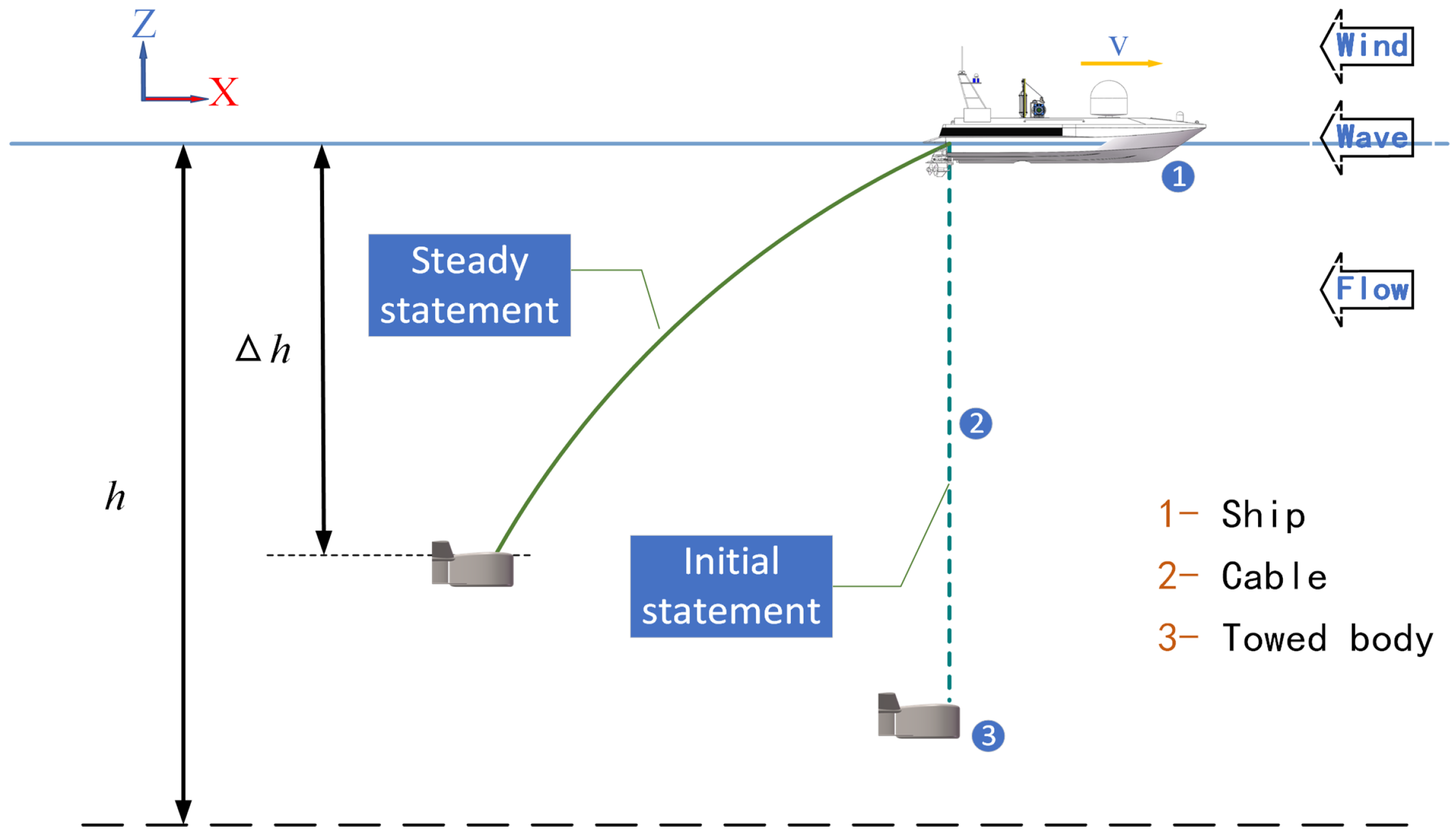
Based on the above mathematical models, a simulation model of the towing system was established. As shown in Figure 5, the towing system consists of a surface vessel, an optoelectronic composite cable and a towed body. The hydrodynamic analysis software OrcaFlex was used to model and simulate the towed cable system.
In this paper, the Pierson-Moskowitz spectrum is used as the sea state wave spectrum, considering a sea state of Level 5 with wind speed of 22 kN, significant wave height of 2.735 m, mean wave period of 6.388 s, and zero-crossing period of 5.909 s. The optoelectronic composite cable is numerically simulated using the Line element, and its structural mechanical parameters are detailed in Table 2. The towed body is represented by the 6D buoy element, and its structural parameters are listed in Table 3.

5.2. Results and Discussions

5.2.1. Influence of CCP and CG Position on Towing Dynamics

Towing systems generally operate in a steady state. The steady-state towing depth and cable tension are two crucial performance indicators, depending on many related factors such as towing speed, drag coefficient, cable density and cable elasticity. During towing, it is generally required that steady-state angles such as trim and heel be as close to 0 as possible, while the oscillation amplitudes of trim, heel, and heading angles after disturbances be as small as possible, with low rates of angle change.
For the operating condition with a cable length of 450 m and a maximum towing speed of 20 kN, a parametric analysis of the towed body’s CG position and CCP position was conducted. CG x-coordinate was sequentially set to 0.3 , 0.4 , and 0.5 , with CCP position adjusted accordingly. The following key indicators were calculated: static stable longitudinal inclination angle of the towed body, towed body depth, dynamic stable longitudinal inclination angle, pitch amplitude, and cable tension at the winch end. The simulation results are shown in Table 4 and Table 5 (angles positive clockwise).
From Table 4, when CG is fixed, the closer the horizontal distance between CCP and CG, the more the towed body assumes a bow-down orientation; as the distance increases, the towed body gradually pitches up. For different CG configurations, there exists an optimal CCP position that maintains the towed body in a basically horizontal equilibrium orientation.
From the hydrodynamic stability analysis in Section 2.2, as towing speed increases, the drag F x and the bow-down moment increase, and the bow-down angle also increases. From Table 5, under the action of towing drag F x , the towed body assumes a bow-down orientation. Therefore, the initial orientation of the towed body is designed to be bow-up. On the other hand, the further forward CG and CCP of the towed body, the greater the restoring moment generated by lift F y . Therefore, where structural space permits, CG and CCP should be placed as far forward as possible. Combining Table 4 and Table 5, when CG coordinates are selected as ( 0.30 , 0 , 0.20 ) and CCP as ( 0.10 , 0 , 0.60 ) , the static longitudinal inclination angle is 4.44 ° , and the longitudinal inclination angle at maximum towing speed is 6.82 ° , resulting in a good trim orientation over the entire towing speed range.
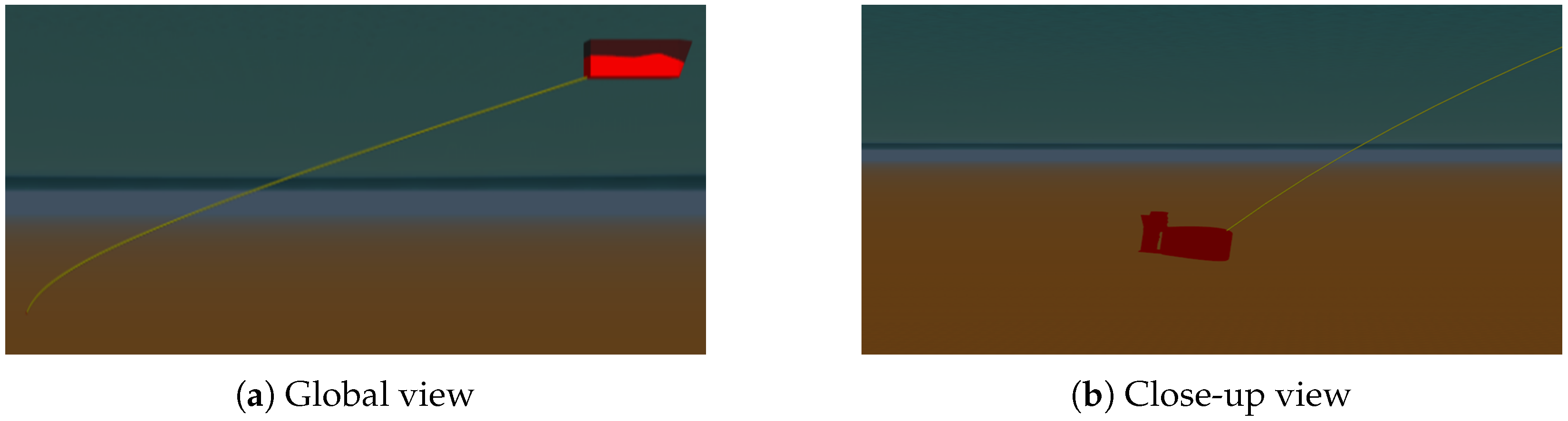
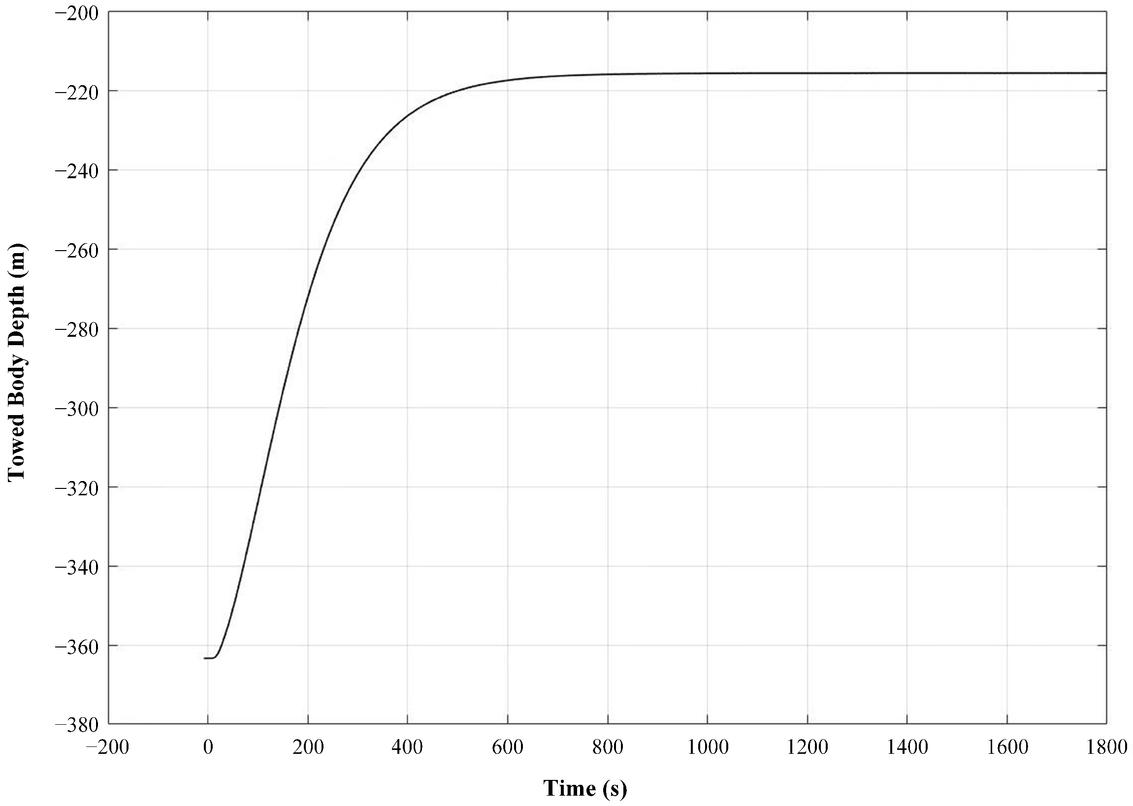
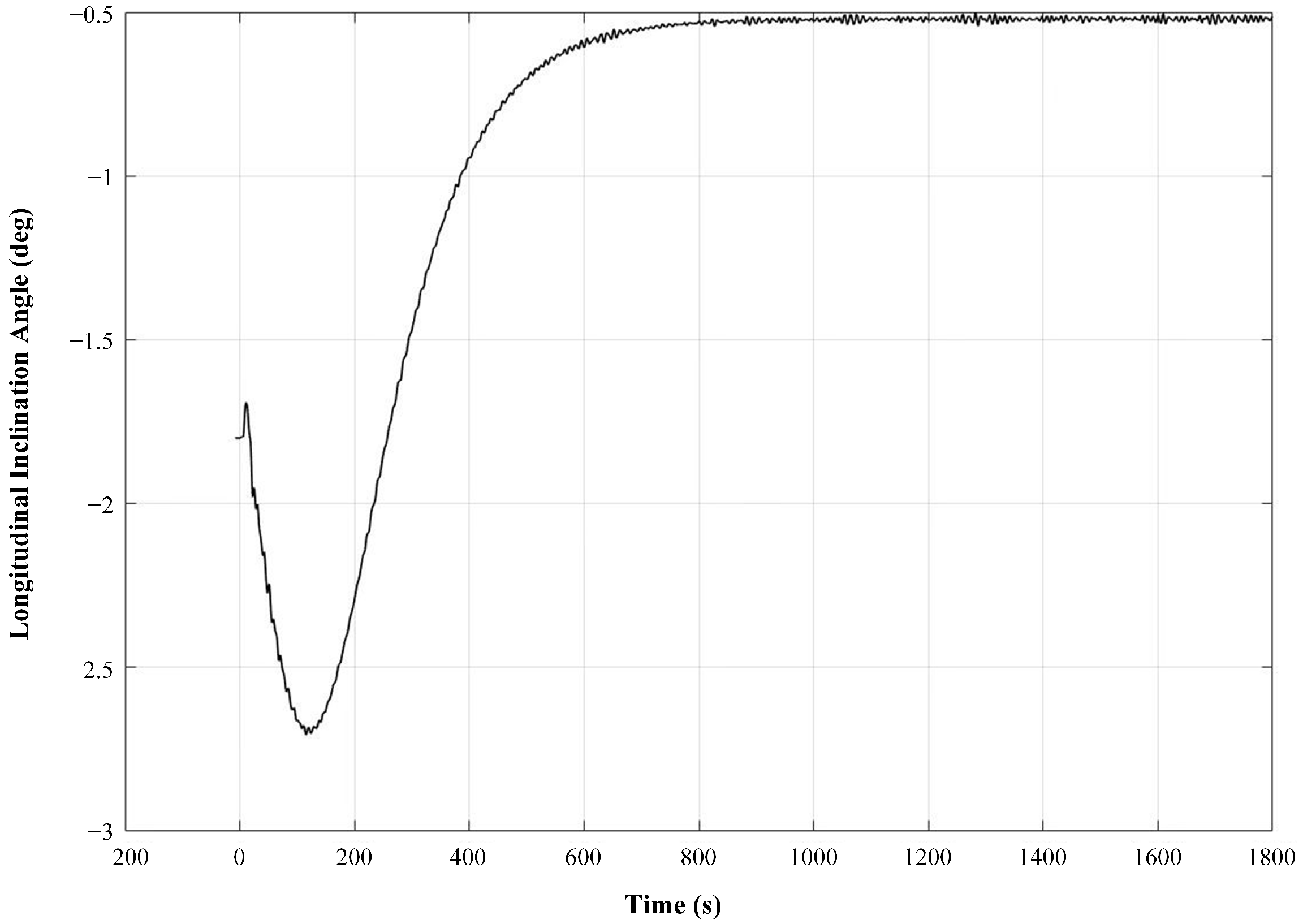
At a towing speed of 20 kN, the dynamic longitudinal inclination angle can be suppressed within 10 ° . The OrcaFlex simulation diagrams are shown in Figure 6a,b, and the simulation results of depth and longitudinal inclination angle are shown in Figure 7 and Figure 8.

5.2.2. Influence of Cable Length on Towing Dynamics

Based on the orientation simulation analysis, CG was selected as ( 0.30 , 0 , 0.20 ) and CCP as ( 0.10 , 0 , 0.60 ) . The following simulations analyze the towing depth and cable tension for towing speeds from 2 kN to 20 kN and cable lengths from 100 m to 450 m, with a simulation time of 1800 s. This paper mainly analyzes the effects of towing speed and cable length on towed body depth, longitudinal inclination angle, pitch amplitude and winch-end cable tension. The results are shown in Table 6 (angles positive clockwise; only data for 4 kN, 12 kN, and 20 kN are shown).
When the cable length is fixed, as towing speed increases, the underwater depth of the towed body gradually decreases, while the longitudinal inclination angle and cable tension at the winch end gradually increase. This can be explained by the Morison equation: fluid resistance on the cable and hydrodynamic forces on the towed body are proportional to the square of the speed. An increase in speed leads to a significant increase in cable tension and hydrodynamic forces, and the bow-down moment causes the longitudinal inclination angle to increase.
When the towing speed is fixed, as cable length increases, the winch-end cable tension gradually increases, the longitudinal inclination angle remains almost unchanged, and the pitch amplitude gradually decreases. Increasing cable length increases the resistance area, enhancing the cumulative fluid resistance, which causes the winch-end cable tension to rise. Meanwhile, the vessel’s rolling motion is transmitted to the towed body through the cable, mainly affecting pitch motion. Shorter cable lengths result in shallower depths, making the towed body more directly affected by vessel oscillations, leading to larger pitch amplitudes. As cable length increases, the towed body moves farther from the surface vessel, disturbances are reduced, and pitch motion becomes smoother.

5.3. Discussions

To contextualize the present results, a comparison with similar outcomes reported in the English literature is provided. The observed trend that increasing towing speed leads to a bow-down attitude and reduced towing depth is consistent with the findings of Wu et al. [11], who reported that the towed vehicle moves upward and backward with increasing towing speed under non-controlled operation. The present study further quantifies this relationship for a water-droplet-shaped towed body, showing that the dynamic pitch angle increases from 5.71 ° to 10.20 ° as the CG position varies from 0.05 m to 0.20 m at 20 kN speed.
The influence of cable length on system dynamics also aligns with Wu et al. [11], who observed that cable deformation and internal tension increase with towing speed. The present study extends this finding by systematically quantifying the relationship between cable length (100 m to 450 m) and pitch amplitude, demonstrating that longer cables effectively attenuate pitch oscillations—from 1.60 ° at 100 m to 0.25 ° at 450 m at 20 kN, due to increased distance from surface vessel disturbances.
Regarding the optimization of stability parameters, the present study shares conceptual similarities with the adaptive control approaches of Teixeira et al. [12], who adjusted the vehicle’s center of gravity indirectly through control actuation. However, the present work takes a fundamentally different approach by optimizing the passive stability characteristics through direct parametric variation of CG and tow point positions, without requiring active control effort. This passive optimization strategy offers advantages in terms of simplicity, reliability, and reduced energy consumption, making it particularly suitable for long-duration towing operations where active control may be constrained by power limitations.

6. Conclusions

Based on hydrodynamics theory, this paper conducted a stability analysis of underwater towed body towing. The CFD method was used to calculate the hydrodynamic parameters. The hydrodynamic analysis software OrcaFlex was used to optimize CG and CCP. Based on the simulation results, the influences of towing speed and cable length on towing stability were clarified. The following conclusions can be drawn from the above simulation analysis:
  • The static stability of the towed body in the towing system is mainly affected by the combined effects of its CB, CG, and CCP position. When CB is fixed, the towed body can be maintained in a horizontal orientation in static water by reasonably configuring the positions of CG and CCP.
  • In addition to CB, CG and CCP, the hydrodynamic stability of the towed body also depends largely on CF position. The hydrodynamic forces and the moments they generate vary with towing speed and towed body orientation and are key factors in maintaining the dynamic towing stability of the towed body.
  • During the motion of the towing system, performance indicators such as towed body depth, longitudinal inclination angle, pitch amplitude and cable tension are significantly affected by the coupled influence of towing speed and cable length, and their variation laws conform to hydrodynamic theory. The towing system designed in this paper can effectively keep the longitudinal inclination angle of the towed body below 10 ° for towing speeds up to 20 kN.

Author Contributions

Conceptualization, J.C. and L.C.; methodology, J.C.; software, J.C.; validation, J.C. and L.C.; formal analysis, J.C.; investigation, J.C.; resources, J.C.; data curation, J.C.; writing—original draft preparation, J.C.; writing—review and editing, L.C.; visualization, J.C.; supervision, L.C.; project administration, L.C.; funding acquisition, L.C. All authors have read and agreed to the published version of the manuscript.

Funding

This research received no external funding.

Institutional Review Board Statement

Not applicable.

Informed Consent Statement

Not applicable.

Data Availability Statement

The data presented in this study are available on request from the corresponding author.

Acknowledgments

The authors would like to acknowledge the technical support from the Ocean Institute, Northwestern Polytechnical University.

Conflicts of Interest

The authors declare no conflicts of interest.

Abbreviations

CGCenter of Gravity
CBCenter of Buoyancy
CCPCable Connecting Point
CFCenter of Hydrodynamic Force
CFDComputational Fluid Dynamics
MPCModel Predictive Control
MDOMultidisciplinary Design Optimization

References

  1. Holmes, J.D.; Carey, W.M.; Lynch, J.F.; Newhall, A.E.; Kukulya, A. An autonomous underwater vehicle towed array for ocean acoustic measurements and inversions. In Proceedings of the Europe Oceans 2005, Brest, France, 20–23 June 2005; IEEE: Piscataway, NJ, USA, 2005. [Google Scholar]
  2. Pallayil, V.; Lin, Y.T.; Fischell, E.; Noguchi, Y.; Maki, T. Integration and testing of a low-profile hydrophone array with REMUS 100 AUV for seabed characterization and marine mammal detection application. In Proceedings of the 2019 IEEE Underwater Technology (UT), Kaohsiung, Taiwan, 16–19 April 2019; IEEE: Piscataway, NJ, USA, 2019. [Google Scholar]
  3. Palomeras, N.; Furfaro, T.; Williams, D.P.; Carreras, M.; Dugelay, S. Automatic target recognition for mine countermeasure missions using forward-looking sonar data. IEEE J. Ocean. Eng. 2022, 47, 141–161. [Google Scholar] [CrossRef]
  4. Savini, A.; Pinson, S.; Bistacchi, A.; Etiope, G.; Holland, C.W. Imaging shallow gas migration pathways in a mud-volcano province using an autonomous underwater vehicle (Malta Plateau, Mediterranean Sea). Near Surf. Geophys. 2018, 16, 681–699. [Google Scholar] [CrossRef]
  5. Leech, C.M.; Tabarrok, B. The cable geometry for a towed submersible. Int. J. Mech. Sci. 1995, 37, 1079–1087. [Google Scholar] [CrossRef]
  6. Ablow, C.M.; Schechter, S. Numerical simulation of undersea cable dynamics. Ocean Eng. 1983, 10, 443–457. [Google Scholar] [CrossRef]
  7. Huang, S. Dynamic analysis of three-dimensional marine cables. Ocean Eng. 1994, 21, 587–605. [Google Scholar] [CrossRef]
  8. Buckham, B.; Driscoll, F.R.; Nahon, M. Development of a finite element cable model for use in low-tension dynamics simulation. J. Appl. Mech. 2004, 71, 476–485. [Google Scholar] [CrossRef]
  9. Xu, X.S.; Zou, Z.J. Robust dynamics calculation for underwater moving slender bodies via flexible segment model based optimization. Ocean Eng. 2015, 108, 493–503. [Google Scholar] [CrossRef]
  10. Park, J.; Kim, N. Dynamics modeling of a semi-submersible autonomous underwater vehicle with a towfish towed by a cable. Int. J. Nav. Archit. Ocean Eng. 2015, 7, 409–425. [Google Scholar] [CrossRef]
  11. Wu, J.M.; Yang, X.Y.; Xu, S.Y.; Han, X.X. Numerical investigation on underwater towed system dynamics using a novel hydrodynamic model. Ocean Eng. 2022, 247, 110632. [Google Scholar] [CrossRef]
  12. Teixeira, F.C.; Aguiar, A.P.; Pascoal, A. Nonlinear adaptive control of an underwater towed vehicle. Ocean Eng. 2010, 37, 1193–1220. [Google Scholar] [CrossRef]
  13. Londhe, P.S.; Dhadekar, D.D.; Patre, B.M.; Waghmare, L.M. Uncertainty and disturbance estimator based sliding mode control of an autonomous underwater vehicle. Int. J. Dyn. Control 2017, 5, 1122–1138. [Google Scholar]
  14. Gong, P.; Yan, Z.P.; Zhang, W.; Tang, J.L. Trajectory tracking control for autonomous underwater vehicles based on dual closed-loop of MPC with uncertain dynamics. Ocean Eng. 2022, 265, 112697. [Google Scholar] [CrossRef]
  15. Kostenko, V.V.; Tolstonogov, A.Y.; Mokeeva, I.G. The combined AUV motion control with towed magnetometer. In Proceedings of the 2019 IEEE Underwater Technology (UT), Kaohsiung, Taiwan, 1–5 April 2019; IEEE: Piscataway, NJ, USA, 2019. [Google Scholar]
  16. Yamaguchi, S.; Koterayama, W.; Yokobiki, T. Development of a motion control method for a towed vehicle with a long cable. In Proceedings of the 2000 International Symposium on Underwater Technology, Tokyo, Japan, 23 May 2000; IEEE: Piscataway, NJ, USA, 2000. [Google Scholar]
  17. Liu, C.; Li, J.J.; Yang, S.L.; Xiang, X.B. Simultaneously tracking and pitch control of underwater towed vehicle with multiple elevators: A finite-time fuzzy approach. Int. J. Fuzzy Syst. 2023, 25, 264–274. [Google Scholar]
  18. Ferri, G.; Munafò, A.; Lepage, K.D. An autonomous underwater vehicle data-driven control strategy for target tracking. IEEE J. Ocean. Eng. 2018, 43, 323–343. [Google Scholar] [CrossRef]
  19. Chen, X.; Wang, P.; Zhang, D.Y.; Dong, H.C. Gradient-based multidisciplinary design optimization of an autonomous underwater vehicle. Appl. Ocean Res. 2018, 80, 101–111. [Google Scholar] [CrossRef]
  20. Bidoki, M.; Mortazavi, M.; Sabzehparvar, M. A new approach in system and tactic design optimization of an autonomous underwater vehicle by using multidisciplinary design optimization. Ocean Eng. 2018, 147, 517–530. [Google Scholar] [CrossRef]
  21. Liu, X.Y.; Yuan, Q.Q.; Zhao, M.; Cui, W.C.; Ge, T. Multiple objective multidisciplinary design optimization of heavier-than-water underwater vehicle using CFD and approximation model. J. Mar. Sci. Technol. 2017, 22, 135–148. [Google Scholar]
  22. Alam, K.; Ray, T.; Anavatti, S.G. An evolutionary approach for the design of autonomous underwater vehicles. In Proceedings of the 25th International Australasian Joint Conference on AI 2012: Advances in Artificial Intelligence, Sydney, Australia, 4–7 December 2012; Springer: Berlin/Heidelberg, Germany, 2012. [Google Scholar]
Figure 1. Force analysis of longitudinal profile projection.
Jmse 14 01342 g001
Figure 2. Force analysis of cross-sectional projection.
Jmse 14 01342 g002
Figure 3. Hydrodynamic analysis of longitudinal profile projection.
Jmse 14 01342 g003
Figure 4. Hydrodynamic analysis of horizontal plane projection.
Jmse 14 01342 g004
Figure 5. Numerical simulation model of the underwater towing system.
Jmse 14 01342 g005
Figure 6. Schematic diagram of the towing system.
Jmse 14 01342 g006
Figure 7. Variation results of towed body depth.
Jmse 14 01342 g007
Figure 8. Variation results of towed body longitudinal inclination angle.
Jmse 14 01342 g008
Table 1. Hydrodynamic parameters of the towed body.
x-Directionz-Direction
Drag/N1261403
Drag coefficient0.10150.675
Projected area/mm2568,000979,000
Table 2. Cable parameters.
Parameter Value
Unit mass in air/(te/m) 0.0016
Cable length/m Adjustable
Minimum bending radius/mX0.35
Y0.35
Axial stiffness/kN 280
Drag coefficient/mX1.2
Y1.2
Z0.1
Diameter/mOuter0.022
Inner0
Table 3. Towed body parameters.
ParameterValue
Dimension/m 1.4 × 1.0 × 0.95
Displaced volume/m30.262
Weight/kg600
CG position/m(Adjustable, 0, 0.20)
CCP position/m(Adjustable, 0, 0.60)
Moment of inertia/kg·m2(31.99, 78.34, 69.23)
CB position/m(0.503, 0, 0.315)
Table 4. Static trim of the towed body under different centers of gravity and cable connecting points.
CG Position/mCCP Position/mStatic Longitudinal Inclination Angle/deg
(0.30, 0, 0.20)(0.20, 0, 0.60)7.23
(0.15, 0, 0.60)1.41
(0.10, 0, 0.60)−4.44
(0.05, 0, 0.60)−10.20
(0.40, 0, 0.20)(0.35, 0, 0.60)3.88
(0.325, 0, 0.60)0.98
(0.30, 0, 0.60)−1.92
(0.25, 0, 0.60)−7.69
(0.20, 0, 0.60)−13.30
(0.15, 0, 0.60)−18.66
(0.50, 0, 0.20)(0.475, 0, 0.60)−2.62
(0.45, 0, 0.60)−5.51
(0.40, 0, 0.60)−11.19
(0.35, 0, 0.60)−16.66
(0.30, 0, 0.60)−21.83
(0.25, 0, 0.60)−26.66
Table 5. Estimation of towing orientation under different centers of gravity and cable connecting points at 20 kN speed.
CG Position/mCCP Position/mDepth/mCable Tension/kNDynamic Trim/degPitch Amplitude/deg
x = 0.3(0.20, 0, 0.60)96.7172.81410.200.24
(0.15, 0, 0.60)94.5172.3258.390.25
(0.10, 0, 0.60)93.6171.8526.820.25
(0.05, 0, 0.60)93.1171.5745.710.26
x = 0.4(0.35, 0, 0.60)106.4175.15016.760.18
(0.325, 0, 0.60)103.7174.25514.430.15
(0.30, 0, 0.60)101.3173.57112.540.22
(0.25, 0, 0.60)97.6172.6319.670.28
(0.20, 0, 0.60)94.7172.0317.610.18
(0.15, 0, 0.60)92.6171.6456.060.20
x = 0.5(0.475, 0, 0.60)123.9184.60637.920.14
(0.45, 0, 0.60)118.3180.35428.810.22
(0.40, 0, 0.60)108.1175.75318.260.17
(0.35, 0, 0.60)101.3173.59312.630.28
(0.30, 0, 0.60)96.8172.4619.130.28
(0.25, 0, 0.60)93.6171.8236.810.32
Table 6. Estimation of towing orientation under different cable release lengths.
Speed/kNCable Length/mDepth/mCable Tension/kNDynamic Trim/degPitch Amplitude/deg
410087.25.733−0.750.38
150120.25.987−0.790.12
200143.26.432−0.730.06
250176.67.902−0.730.07
300192.68.156−0.740.07
350230.19.818−0.730.04
400245.19.884−0.790.06
450277.911.538−0.900.08
1210042.317.4955.271.02
15052.424.0495.260.62
20060.530.6035.240.51
25073.737.3445.230.51
30079.643.9065.250.34
35095.650.6685.250.26
40098.857.2325.250.18
450114.762.6815.320.13
2010032.148.8616.781.60
15042.464.3166.791.12
20049.781.7716.761.02
25057.6101.3216.820.68
30065.9119.8536.770.69
35077.1138.4046.750.72
40082.5156.2316.770.54
45090.6171.8526.820.25
Disclaimer/Publisher’s Note: The statements, opinions and data contained in all publications are solely those of the individual author(s) and contributor(s) and not of MDPI and/or the editor(s). MDPI and/or the editor(s) disclaim responsibility for any injury to people or property resulting from any ideas, methods, instructions or products referred to in the content.