Article

A Time-Domain Substructure Method for Simulating Water–Cylinder Interaction Under Dynamic Loadings Considering Boundary Condition of Free Surface Waves

1
Key Laboratory of Urban Security and Disaster Engineering of Ministry of Education, Beijing University of Technology, Beijing 100124, China
2
International Research Institute of Disaster Science, Tohoku University, Sendai 980-0845, Japan
*
Author to whom correspondence should be addressed.
J. Mar. Sci. Eng. 2025, 13(9), 1814; https://doi.org/10.3390/jmse13091814
Submission received: 18 August 2025 / Revised: 15 September 2025 / Accepted: 18 September 2025 / Published: 19 September 2025
(This article belongs to the Special Issue Wave Loads on Offshore Structure)

Abstract

The dynamic interaction between water and cylindrical structures can significantly affect the dynamic responses and properties of offshore structures. Among the key factors, the free-surface boundary condition plays a crucial role in determining the hydrodynamic forces on cylinders, leading to frequency-dependent added mass and damping effects. Although the dynamic responses of the cylinder can be readily obtained using frequency-domain methods, their computational efficiency is much lower than that of the time-domain methods, and they are not well suited for nonlinear structure analysis. To address this, this study proposes a time-domain substructure method for simulating water–cylinder interaction considering the boundary condition of free surface waves, where the frequency-dependent added mass and added damping are equivalently represented by a spring-dashpot-mass model in time domain. The results indicated that the calculation efficiency of the proposed method has improved by approximately two orders of magnitude compared with the frequency-domain finite element method. Moreover, the water–cylinder interaction can markedly influence the seismic responses with small mass ratios, whereas its effect on wave-induced responses becomes negligible when the wave period exceeds 5 s. The effects of the free-surface boundary condition on the wave responses of the cylinder can be generally negligible, except when the wave period approaches the natural vibration period of the cylinder. In addition, its influence on seismic responses can be ignored when the damping ratio of the cylinder exceeds 0.02.

1. Introduction

Circular cylinders have been widely used in offshore structures, such as offshore wind turbines, cross-sea bridges, and wharves [1,2,3]. Usually, wind load and ocean wave load are the two most important environmental loads for the design of offshore structures, while earthquake loading becomes dominant in regions with high seismic intensity. It is well known that cylinders immersed in water are subjected to additional hydrodynamic forces under dynamic loading due to fluid–structure interaction. These hydrodynamic forces can change the dynamic properties and responses of the structures [4,5,6]. Therefore, water–cylinder interaction must be given particular attention in the design of offshore structures.
The water–cylinder interaction during earthquakes has been well studied in recent decades. Based on the radiation wave theory, the earthquake-induced hydrodynamic force on a circular cylinder, varying uniformly from the bedrock to the water surface, can be derived strictly from the governing equation of the fluid and boundary conditions [7]. The existing studies indicated that the effect of water–cylinder interaction during earthquakes can be replaced by an additional mass, which is called “added mass” [5]. Based on the analytical solutions of the earthquake-induced hydrodynamic force on circular and elliptical cylinders, the simplified formulas of the added mass to simulate the water–cylinder were developed by Li and Yang [8], Jiang et al. [9], and Wang et al. [10]. Furthermore, using highly efficient and accurate numerical methods, Wang et al. [11,12,13] proposed simplified added mass formulations for simulating the dynamic interaction of waves with circular tapered cylinders, inclined circular cylinders, round-ended cylinders, and rectangular cylinders.
The wave–cylinder interaction has also been investigated by many researchers. The Morison equation proposed by Morison et al. [14] and the diffraction wave theory proposed by MacCamy and Fuchs [15] are two major methods to calculate the wave forces on cylinders. The Morison equation is a semi-empirical and semi-theoretical formula to evaluate the wave forces acting on slender cylinders [16,17,18], which is made up of a drag force and a virtual mass force. The diffraction wave theory is mainly used to calculate the wave forces on larger cylinders [19,20,21]. Wave-induced forces can also deform the cylinder, and this deformation generates additional hydrodynamic forces that can be evaluated using radiation wave theory. In addition, Newman [22] provided the fundamental theoretical basis, covering potential flow theory, radiation–diffraction methods, and added-mass and damping formulations, while Molin [23] offers an updated and detailed account of nonlinear wave–structure interactions, including modern issues such as gap resonance and moonpool dynamics. Due to the boundary condition of free surface waves, the effects of the radiated waves generated by cylinder motion can be characterized by frequency-dependent added mass and damping. The closed-form solutions of the added mass and damping coefficients for an oscillating circular cylinder were given by Rahman and Bhatta [24]. The results indicated that the added mass approaches a constant value and becomes frequency-independent, while the added damping converges to zero as the oscillation frequency tends to infinity.
Existing studies have shown that the damping effects of free surface waves can be neglected and the water–cylinder interaction can be approximated by a frequency-independent added mass when the load frequency is high [20]. However, since ocean waves generally occur at relatively low frequencies, both added mass and damping vary significantly within the relevant frequency range. In this case, the dynamic responses of cylinders can be readily evaluated using frequency-domain methods [5]. Nevertheless, the computational efficiency of the frequency-domain methods is much lower than that of the time-domain methods, and they are not well suited for nonlinear structural analysis. The main purpose of this paper is to develop a substructure method in the time domain with high precision and efficiency for simulating water–cylinder interaction while explicitly considering the free-surface boundary condition. In this approach, the frequency-dependent added mass and damping are equivalently represented by a spring–dashpot–mass model in the time domain. This method is both stable and efficient and can be seamlessly integrated with the explicit finite element method. Furthermore, the proposed method is applied to evaluate the effects of the added mass and damping on the dynamic responses of the circular cylinder subjected to wave and earthquake loads.

2. Theoretical Formulation and Solution

The water–cylinder interaction problem under horizontal loading is shown in Figure 1, where the signs (r, θ, z), h and a denote the cylindrical coordinate system, water depth, radius of the cylinder, respectively. The cylinder has a horizontal displacement time history u(t), which induces a radiated hydrodynamic pressure pr(r,θ,z,t). In the analysis of hydrodynamic forces acting on offshore structures, two main approaches are generally employed. The first is Morison’s equation, which is suitable for small-diameter slender structures. In this method, the fluid forces are expressed using empirical inertia and drag coefficients, which are typically dependent on Reynolds number and flow conditions. Morison’s equation enables rapid computation of fluid forces with relatively low computational cost, but its applicability is mainly limited to structures whose dimensions are small compared to the wavelength. The second approach is potential flow theory, which is more suitable for large-scale structures. This theory assumes that the fluid is irrotational, inviscid, and incompressible, and it avoids reliance on empirical lift or drag coefficients. Since this study focuses on large-scale offshore structures, potential flow theory is adopted to solve the water–cylinder interaction.
The governing equation for hydrodynamic pressure pr(r,θ,z,t) is expressed as:
2 P r r 2 + 1 r P r r + 1 r 2 2 P r θ 2 + 2 P r z 2 = 0
where P r = p r e i ω t d t is the Fourier transformation of pr and ω is the load frequency.
The boundary conditions for the radiation wave at bottom, free surface, infinity and interface of cylinder and water can be written as:
P r z | z = 0 = 0
P r z = ω 2 g P r     z = h
lim r r P r r i k P r = 0
P r r | r = a = ρ ω 2 U cos θ
where U = u e i ω t d t denotes the displacement of the cylinder in frequency domain, ρ is the fluid density, and g is the gravitational acceleration.
Using separation of variables and according to boundary conditions in Equations (2)–(5), the hydrodynamic pressure can be obtained by:
P r = ρ a ω 2 cos θ j = 0 d j S j cosh k j z 0 h U cosh k j z d z
S j = H 1 1 k j a k j a H 1 1 k j a
d j = 2 h + ω 2 / g 1 sinh 2 k j h
where H n 1 is Hankel function of the first kind of order n; for j = 1,2,3… kj = j, k0 and κj can be obtained by the following equations:
k 0 tanh k 0 h = ω 2 g and   κ j tan κ j h = ω 2 g
For a circular cylinder with a rigid motion, the hydrodynamic force component per unit length can be obtained as:
F x r = 0 2 π P r a cos θ d θ = ρ π a 2 ω 2 U j = 0 J d j S j cosh k j z k j sinh k j h
where J denotes the number of modes. It should be noted that Equation (10) will be used to obtain the discrete hydrodynamic force on the nodes of the circular cylinder, and the corresponding added mass and damping due to the water–cylinder interaction will be further obtained.

3. Method of Rational Function Approximation

It should be noted that the radiation force (FRad) due to the water–structure interaction can be defined as follows for a single-frequency motion in frequency domain:
F R a d = M h ω ω 2 U i ω C h ω U
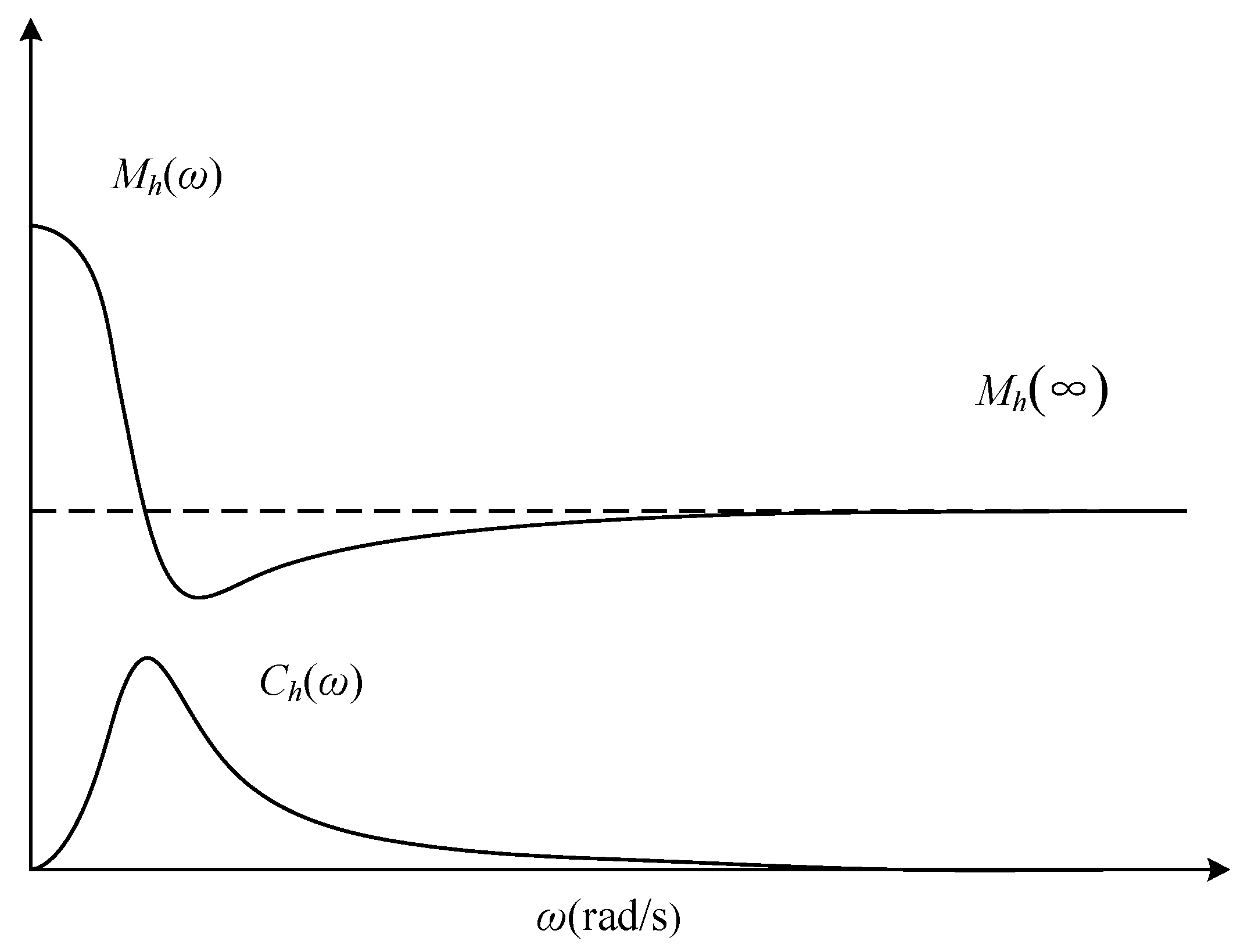
where Mh(ω) and Ch(ω) denote the frequency-dependent added mass and damping, respectively. Figure 2 show the typical frequency-dependent added mass and damping coefficients for the water–cylinder interaction, where the added mass becomes constant and frequency-independent whereas the added damping converges to zero when the load frequency tends to infinity. Therefore, the added mass Mh(ω) can be further rewritten as:
M h ω = m h ω + M h
where Mh() represents the added mass with load frequency tends to infinity.
Therefore, the radiation force FRad can be rewritten as the following dynamic stiffness relationship:
F R a d = S h ω U = H h ω U + M h ω 2 U
H h ω = m h ω ω 2 + i ω C h ω
where Sh(ω) and Hh(ω) denote the dynamic stiffness coefficient.
Correspondingly, the discrete hydrodynamic force on the circular cylinder at ith node with vertical coordinate equal to zi ( F x , i r ) can be expressed as:
F x , i r z i = S h , i ω U i ω = H h , i ω M h , i ω 2 U i ω
H h , i ω = m h , i ω ω 2 + i ω C h , i ω
According to Equation (10), Mh,i(), mh,i(ω) and Ch,i(ω) can be expressed as:
M h , i = Re w i ρ π a 2 j = 0 d j S j cosh k j × k j sinh k j h
m h , i ω = Re w i ρ π a 2 j = 0 d j S j cosh k j z i k j sinh k j h M i
C h , i ω = Im w i ρ π a 2 ω j = 0 d j S j cosh k j z i k j sinh k j h
where Re and Im denote extracting the real part and imaginary part; and w i = z i + 1 z i 1 / 2 .
Although the solution in the frequency domain in Equation (15) can be transformed back into time domain by the inverse Fourier transform, the convolution involved in this process introduces temporal globality. As a result, the response at a given instant is dependent on the responses at all the preceding instants. This significantly increases the computational cost, particularly for long-duration simulations, compared with direct time-domain integration methods. In addition, the frequency-domain method has limitations in accounting for structural nonlinearities. To overcome these issues, a high-order time-domain approximation based on the temporal localization method is adopted to solve Equaiton (16). Specifically, the frequency-independent added mass Mh,i(ω) is replaced by a mass element. Then, the frequency-dependent dynamic stiffness coefficient Hh,i(ω) are approximated as a rational function as given in Equation (20). Finally, the rational function is equivalently transformed into time domain equivalently by introducing the auxiliary variables, which will be elaborately introduced in Section 4.
The rational approximation function of the dynamic stiffness coefficient H h , i ω can be expressed as
H h , i ω H ˜ h , i ω = ρ π a 2 p 0 + p 1 ( i ω ) + + p N + 1 ( i ω ) N + 1 q 0 + q 1 ( i ω ) + + q N ( i ω ) N
where N is the order number of the rational function, with higher values of N leading to improved approximation accuracy; and pn (n = 0,…, N + 1) and qn (n = 0,…, N) are the undetermined real constants.
Furthermore, the dynamic stiffness coefficient S h , i ω is rewritten as
S h , i ω ρ π a 2 p 0 + p 1 ( i ω ) + + p N + 1 ( i ω ) N + 1 q 0 + q 1 ( i ω ) + + q N ( i ω ) N M h ω ω 2
To identify the coefficients of the rational function in Equation (20), numerical methods are required. The least-squares method is commonly employed to approximate the frequency-domain data obtained from Equation (16) by the rational function form expressed in Equation (20) [25]. By substituting s = , Equation (20) can be expressed in transfer function form without altering its coefficients, which facilitates stability analysis. According to modern control theory [26], a stable transfer function requires all poles to have negative real parts, as indicated in Equation (22). However, conventional identification methods [25] do not guarantee this condition and may yield transfer functions with poles in the right-half complex plane, leading to instability. For water–cylinder interaction systems, such unstable transfer function would cause divergent structural responses and physically unrealistic results. To avoid this, stability constraints-such as those defined in Equation (22)—must be enforced during the identification process.
Re roots   of   q < 0
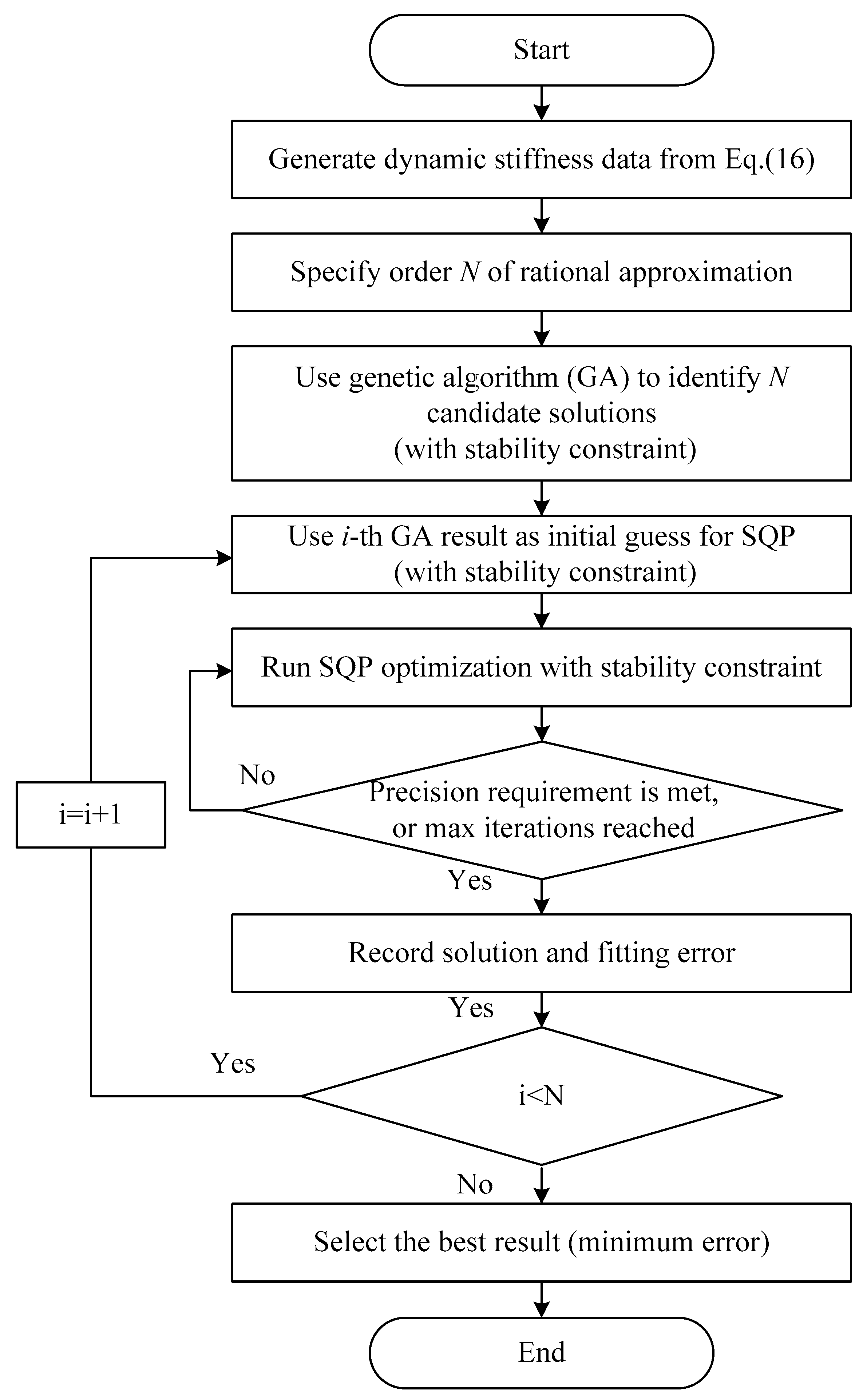
To this end, a more flexible identification method capable of incorporating nonlinear constraints is needed. Inspired by the strategy proposed by Tang et al. [27] for identifying frequency response functions in semi-infinite media, this study adopts a hybrid identification method combining Genetic Algorithm (GA) and Sequential Quadratic Programming (SQP). The method takes advantage of GA’s global search capability and SQP’s high local optimization accuracy to ensure both stability and precision. Specifically, GA is used to explore the global parameter space and locate promising solutions, though its accuracy is limited. On the other hand, SQP can refine these solutions with high precision, but it is sensitive to initial guesses and may become trapped in local optima or even fail to converge if poor initial solutions are used. The hybrid method first employs GA for global exploration and selects a few well-performing individuals as initial guesses for SQP, which then performs independent local optimization. Moreover, this hybrid framework allows the stability constraint in Equation (22) to be flexibly incorporated as a nonlinear constraint in the optimization process. The overall identification procedure used in this study is illustrated in Figure 3.
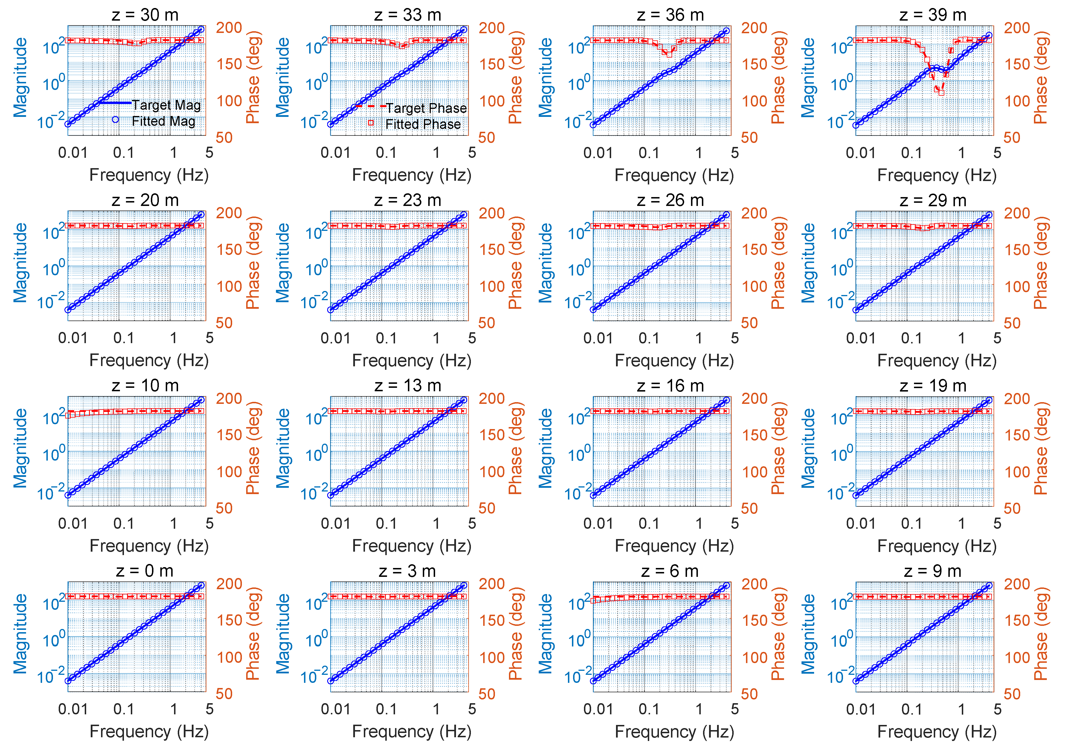
To evaluate the effectiveness of the proposed method, a numerical simulation case is conducted. The cylindrical structure is defined with a radius of a = 2 m and a water depth of h = 40 m, where the number of modes is J = 20. Based on this configuration, frequency-domain dynamic stiffness data are generated from Equation (16) and used as input for the identification procedure. The order N of the rational approximation function is set to 7. The GA is configured with a population size of 50, from which the top 20 individuals are chosen as initial solutions for SQP refinement. Each candidate is then independently optimized using SQP, with a maximum iteration limit of 5000 and a convergence tolerance of 10−12. Such a strict tolerance is intentionally chosen to fully exploit the allowed iterations and achieve the highest possible refinement accuracy for each candidate, thereby enhancing the overall identification precision. It should be noted that these settings are provided as an illustrative example; researchers can adjust the parameters according to their specific objectives and practical requirements. Figure 4 presents the comparison between the identified and target dynamic stiffness-both magnitude and phase-at various vertical locations.
Blue circles represent the fitted magnitude, and blue solid lines denote the target magnitude. Red squares indicate the fitted phase, while red dashed lines correspond to the target phase. The results show that at lower vertical positions, the dynamic stiffness behaves approximately as added inertia, with magnitude proportional to the square of frequency and phase close to 180°. Above approximately 30 m height, the dynamic stiffness exhibits significant variations due to wave motion effects. The proposed identification method accurately captures both magnitude and phase across these positions, confirming its effectiveness in modeling frequency-dependent hydrodynamic behavior.

4. Method of Auxiliary Variable Realization

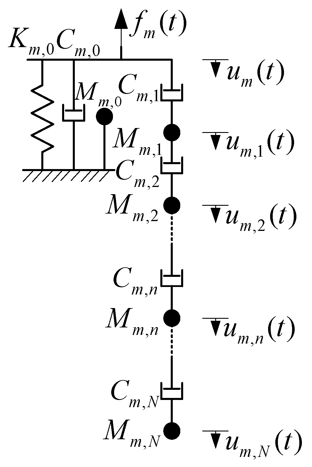
According to the time-domain mechanical model proposed by the authors [28,29], the dynamic stiffness relation in Equation (15) with the dynamic stiffness replaced by the rational function in Equation (21) can be equivalently transformed into a spring-dashpot-mass model shown in Figure 5. It should be noted that the spring-dashpot-mass model by the authors [28,29] has been used to solve the artificial boundary condition absorbing scattered waves and pile–soil interaction. However, this model does not take into account the frequency-independent added mass in Equation (21). Therefore, the new spring-dashpot-mass model in the present study added a parallel mass element ( M m , 0 ), as shown in Figure 5.
For the hydrodynamic force acting on the cylinder at node m, the dynamic equation in the time domain can be expressed as follows:
M m , 0 u ¨ m + C m , 0 + C m , 1 u ˙ m + K m , 0 u m C m , 1 u m , 1 = f m
M m u ¨ m + C m u ˙ m + f m = 0
with
u m = u m , 1 u m , 2 u m , N T
f m = C m , 1 u ˙ m 0 0 T
M m = M m , 1 0 0 0 0 0 M m , 2 0 0 0 0 0 M m , 3 0 0 0 0 0 M m , N 1 0 0 0 0 0 M m , N
C m = C m , 1 + C m , 2 C m , 2 0 0 0 C m , 2 C m , 2 + C m , 3 C m , 3 0 0 0 C m , 3 C m , 3 + C m , 4 0 0 0 0 0 C m , N 1 + C m , N C m , N 0 0 0 C m , N C m , N
where um and fm are the time-domain values of Um and Fm, respectively; um,n (n = 0,…, N) are the real auxiliary variables corresponding to the auxiliary degrees of freedom in the time-domain mechanical model; Mm,0 = Mm(∞); and Km,0, Cm,0 for n = 0,…, N as well as Mm,n (n = 0,…, N) are the undetermined real constants, respectively. These dimensionless constants can be obtained from the coefficients of the rational function, as detailed in [30]. It should be noted that the damping matrix Cm denotes the radiative damping of the fluid due to the radiation waves generated by the motion of the cylinder at node with number m.

Time-Domain Mechanical Model

The finite element equation in the time domain for a cylinder vibrating in water can be expressed as a partitioned matrix form:
M I 0 0 M B u ¨ I u ¨ B + C I C I B C B I C B u ˙ I u ˙ B + K I K I B K B I K B u I u B = 0 f W + f I f B
where the subscripts I and B denote the nodes of the cylinder in air and water, respectively; u is the displacement vector, and the dot over the variable denotes the derivative with respect to time; M, K, and C represent the lumped mass, stiffness, and damping matrices, respectively. f denotes the node force vector; fI and fB are the discrete all external loads on the nodes in air and water, respectively; fW is the discrete hydrodynamic force on the nodes in water due to the motion of the cylinder.
The element mass and stiffness matrices of the cylinder used in the present study are expressed as follows:
M e = m e 1 2 0 0 0 0 l 2 78 0 0 0 0 1 2 0 0 0 0 l 2 78
K e = E I e l 3 12 6 l 12 6 l 6 l 4 l 2 6 l 2 l 2 12 6 l 12 6 l 6 l 2 l 2 6 l 4 l 2
where Me and Ke are the element mass and stiffness matrices, respectively; l is the length of the element; E is the elasticity modulus of the pile; me is the unit mass; and Ie is the unit moment of inertia.
For a cylinder with Q nodes in water, the vector fW can be expressed as follows:
f W = f 1           f m f Q T
where the nodal hydrodynamic force fm is obtained by Equation (19).
Substituting Equation (23) into Equation (32), we can obtain the following:
M B u ¨ B + C B u ˙ B + K B u B + C Q 1 B u Q 1 = f W
M B = m w , 1 0 0 0 0 0 m w , 2 0 0 0 0 0 0 0 0 0 0 m w , M 1 0 0 0 0 0 m w , M
K B = K 1 , 0 0 0 0 0 0 K 2 , 0 0 0 0 0 0 0 0 0 0 0 K M 1 , 0 0 0 0 0 0 K M , 0
C B = C 1 , 0 + C 1 , 1 0 0 0 0 0 C 2 , 0 + C 2 , 1 0 0 0 0 0 0 0 0 0 0 C M 1 , 0 + C M 1 , 1 0 0 0 0 0 C M , 0 + C M , 1
C Q 1 B = C 1 , 1 0 0 0 0 0 C 2 , 1 0 0 0 0 0 0 0 0 0 0 C Q 1 , 1 0 0 0 0 0 C Q , 1
u Q 1 = u 1 , 1 u 2 , 1 u Q , 1 T
By substituting Equation (33) into Equation (29), the dynamic equation can be rewritten as the following:
M I 0 0 M B + M B u ¨ I u ¨ B + C I C I B C B I C B + C B u ˙ I u ˙ B + K I K I B K B I K B K B u I u B = 0 C Q 1 B u Q 1 + f I f B
According to Equation (24), we can obtain the following dynamic equation:
M Q u ¨ Q + C Q u ˙ Q + f Q B = 0
M Q = M 1 0 0 0 0 0 M 2 0 0 0 0 0 M Q 1 0 0 0 0 M Q
C Q = C 1 0 0 0 0 0 C 2 0 0 0 0 0 C Q 1 0 0 0 0 C Q
f Q B = f 1 f 2 f Q T
u Q = u 1 u 2 u Q T
According to Equations (25), (26), (37)–(44), the final dynamic equation can be expressed as follows:
M u ¨ + C u ˙ + K u = f
where u, M, C, and K are the total displacement vector, mass matrix, damping matrix, and stiffness matrix, respectively. It should be noted that the damping matrix C denotes the total damping effects due to the structural damping and the radiative damping of the fluid. The detailed process of obtaining u, M, C and K can be expressed as:
u = u I T u B T u 1 T u 2 T u M T T
f = f I f B 0 0 0 T
M = M I 0 0 0 0 0 0 M B + M B 0 0 0 0 0 0 M 1 0 0 0 0 0 0 M 2 0 0 0 0 0 0 M M 1 0 0 0 0 0 0 M M
C = C I C I B 0 0 0 0 C B I C B + C B C B 1 C B 2 C B ( M 1 ) C B M 0 C 1 B C 1 0 0 0 0 C 2 B 0 C 2 0 0 0 C ( M 1 ) B 0 0 C M 1 0 0 C M B 0 0 0 C M
K = K I K I B 0 0 0 0 K B I K B + K B 0 0 0 0 0 0 0 0 0 0 0 0 0 0 0 0 0 0 0 0 0 0 0 0 0 0 0 0
C B m = C m B T = C m , 1 1 0 0 0
Equation (45) can be solved by the standard direct time integration algorithms, such as the implicit Newmark and Wilson algorithms and the explicit central difference algorithm. In this study, the Newmark-β method is adopted to solve Equation (45).
Based on the above developments, the order of computing each component of the developed model can be summarized as follows. First, the discrete added mass Mh,i(∞) and mh,i(ω), as well as the added damping Ch,i(ω), are obtained by Equations (17)–(19). Correspondingly, the dynamic stiffness coefficient Hh,i(ω) is calculated by Equation (16). Second, the exact dynamic stiffness coefficient Hh,i(ω) is then transformed into the form of rational approximation shown in Equation (20) by using the hybrid identification method combining Genetic Algorithm and Sequential Quadratic Programming. Third, the real constants pn and qn obtained in Equation (20) are used to calculate the value of spring, dashpot, and mass in Equations (23) and (24). Fourth, the element mass and stiffness matrices of the cylinder are obtained by Equations (30) and (31). Fifth, the finite element equation, Equation (45), is obtained by integrating external loads and boundary conditions, the element mass and stiffness matrices of the cylinder, and the spring, dashpot and mass matrices of the water–cylinder interaction. Finally, the finite element equation, Equation (45), is solved using the Newmark-β method.

5. Results and Discussions

In this section, the developed method is applied to investigate the effects of free surface waves on the dynamic responses of the circular cylinder subjected to wave and earthquake loadings. The water density is ρ = 1000 kg/m3 and the water depth is h = 40 m. The radius of the cylinder is a = 2 m, and its length is equal to the water depth. The cylinder is uniformly discretized into twenty elements along the vertical direction. The elastic modulus and density of the cylinder are 30 GPa and 2500 kg/m3, respectively. The variation in the natural vibration period is achieved by adjusting the mass of the upper structure, where the mass ratio Rm, defined as the ratio of the structural mass to the mass of displaced water, was used to denote variation in structural mass. Rayleigh damping is used to consider the damping effect of the structure, with the damping ratio denoted by ξ.
The analytical solution of the wave force on a circular cylinder developed by MacCamy and Fuchs [15] is adopted in this study. The resultant circumferential wave force on the circular cylinder at height z (fI) is expressed as follows:
f I z = ρ 2 g H w cosh ( k z ) k cosh ( k h ) A k a sin ω 0 t
A k a = 1 J 1 k a 2 + Y 1 k a 2
g k 0 tanh ( k 0 h ) = ω 0 2
where k denotes the wave number, ω0 = 2π/Tw is the wave angular frequency, Tw denotes the wave period, Hw denotes the wave height, J1(·) is the Bessel function of order one of the first kind, Yn(·) is the Bessel function of order one of the second kind, and the prime denotes a derivative with respect to the argument. The wave height is Hw = 4 m in the present study.
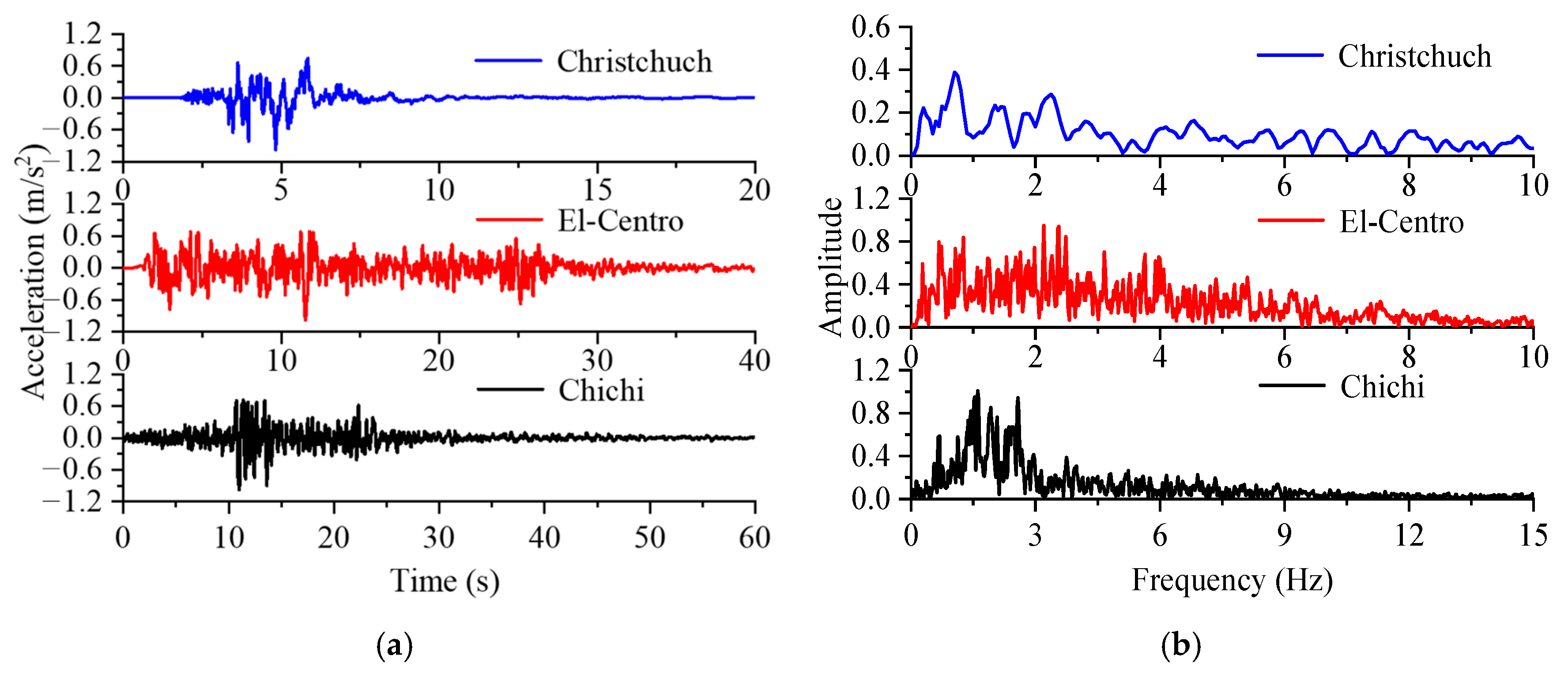
To investigate the effects of water–cylinder interaction on seismic responses, three seismic waves—Chichi, El-Centro, and Christchurch earthquakes—are considered. The acceleration time history and frequency spectrum of the three seismic waves are shown in Figure 6, with a peak acceleration of 0.1 g. The time history of the corresponding ground displacement can be extracted by integration of acceleration.
The dynamic responses of the cylinder are analyzed under three scenarios: neglecting water–cylinder interaction, considering water–cylinder interaction with the boundary condition of free surface waves, and considering water–cylinder interaction while neglecting the boundary condition of free surface waves. For brevity, these cases are denoted as “No water–cylinder interaction”, “With free waves,” and “Without free waves,” respectively. The simulation parameters used in the present study are given in Table 1. In addition, the simulated cases for the wave and earthquake loads are given in Table 2. The convergence tests for time step sizes and mesh independence are first conducted in the case of a cylinder under wave load with wave period Tw = 8 s, mass ratio Rm = 5.08, and damping ratio ξ = 0.02. The results of the convergence test for time step sizes and mesh independence verification are given in Table 3 and Table 4, respectively. It can be seen that the time step size for the Newmark-β method set as 0.01 s, and the element size set as 2 m are sufficient in the present study.

5.1. Verification

A cylinder with a mass ratio Rm = 5.08 and a damping ratio ξ = 0.02 is used to verify the proposed method. The results are compared with those obtained from the frequency-domain finite element method (FEM) [5]. Figure 7 shows the comparison of these two methods under wave load with a wave period equal to 8 s, and Figure 8 shows the comparison of these two methods under the El-Centro seismic wave, where the time history of the displacement on the cylinder head is given. It can be seen that the proposed time-domain substructure method agrees well with the frequency-domain FEM. Notably, the computational efficiency of the time-domain substructure method is much higher than that of frequency-domain FEM. For a wave load of 100 s duration, the computation times for the proposed method and frequency-domain FEM are 0.147 s and 18.234 s, respectively. For the El-Centro seismic wave with a duration of 50 s, the corresponding computation times are 0.056 s and 9.048 s, respectively.

5.2. Wave Loading

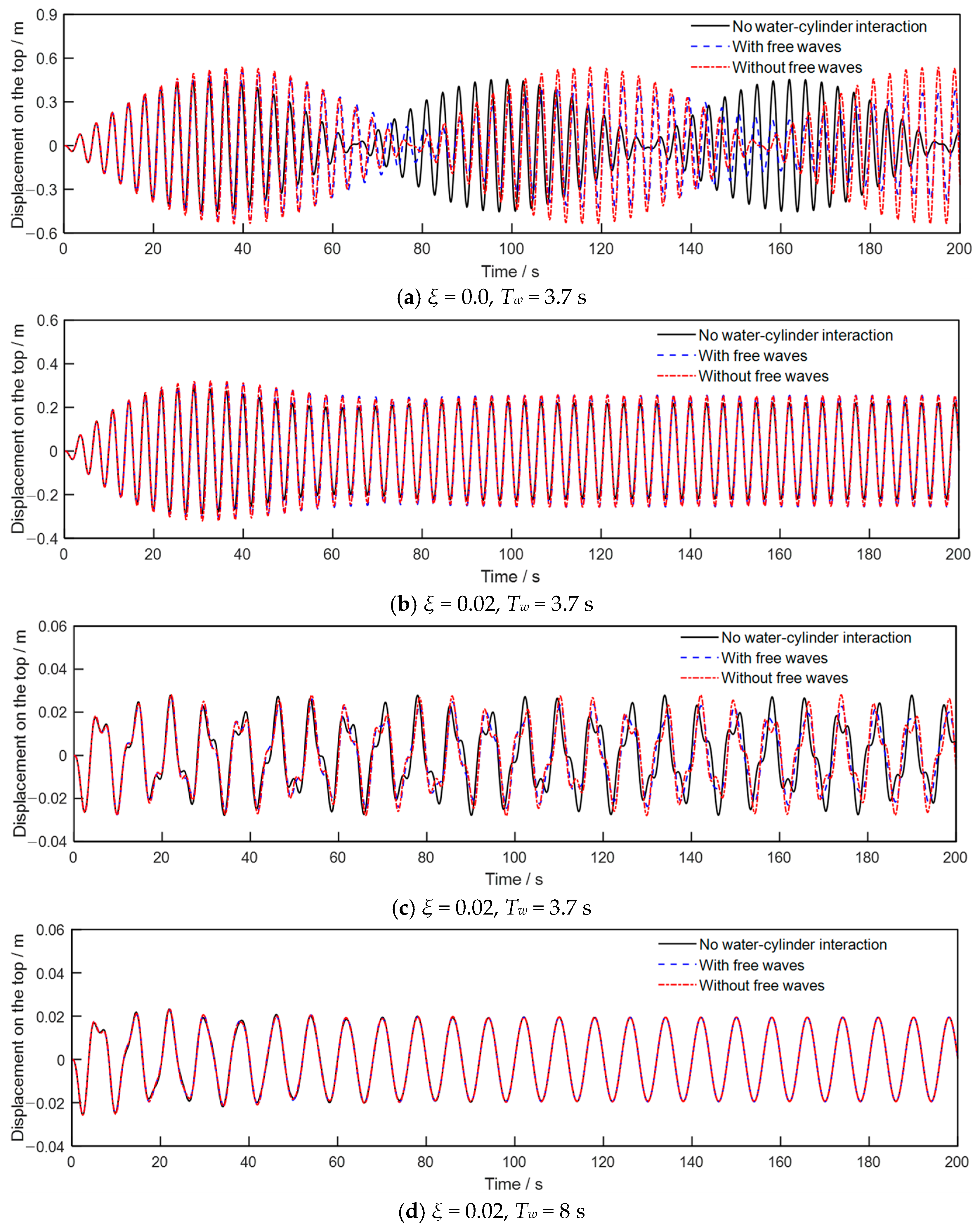
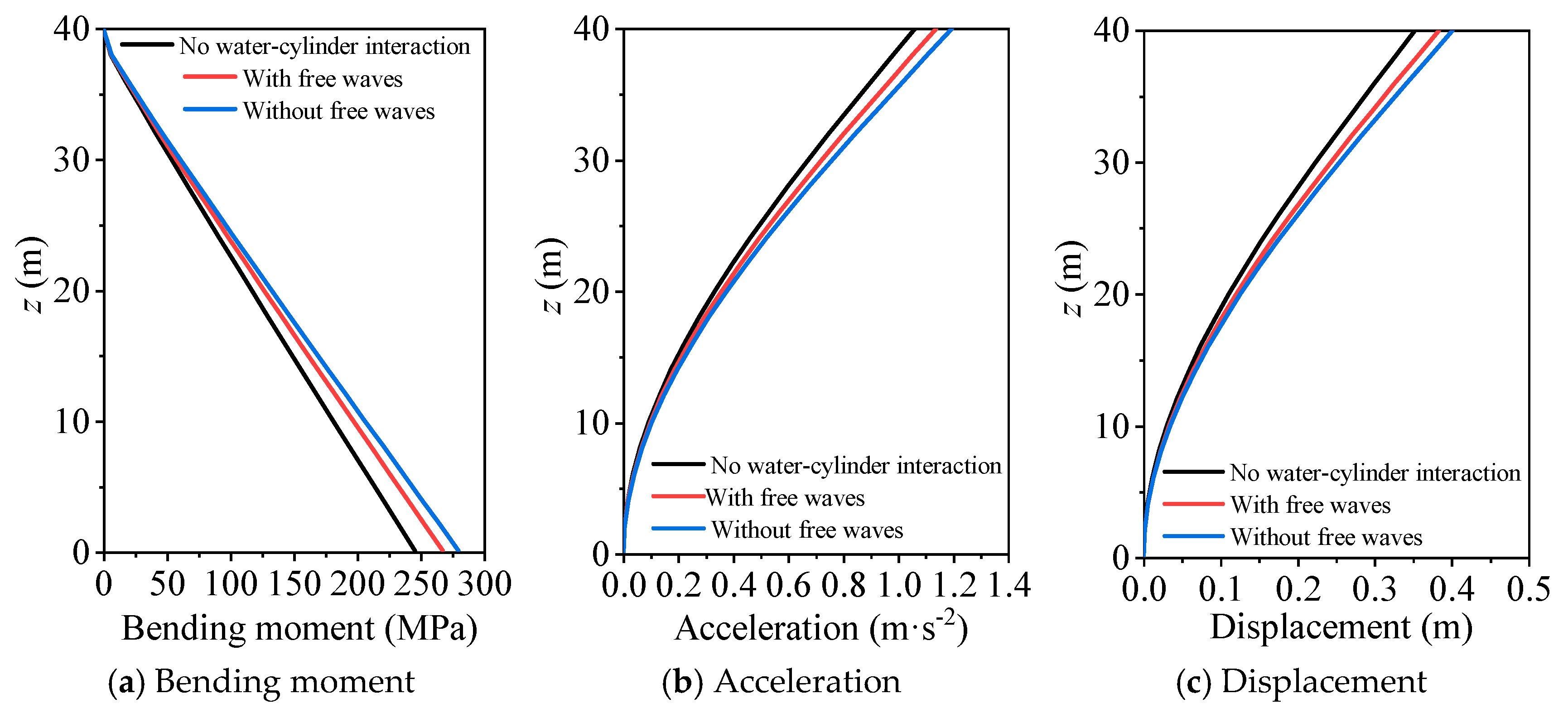
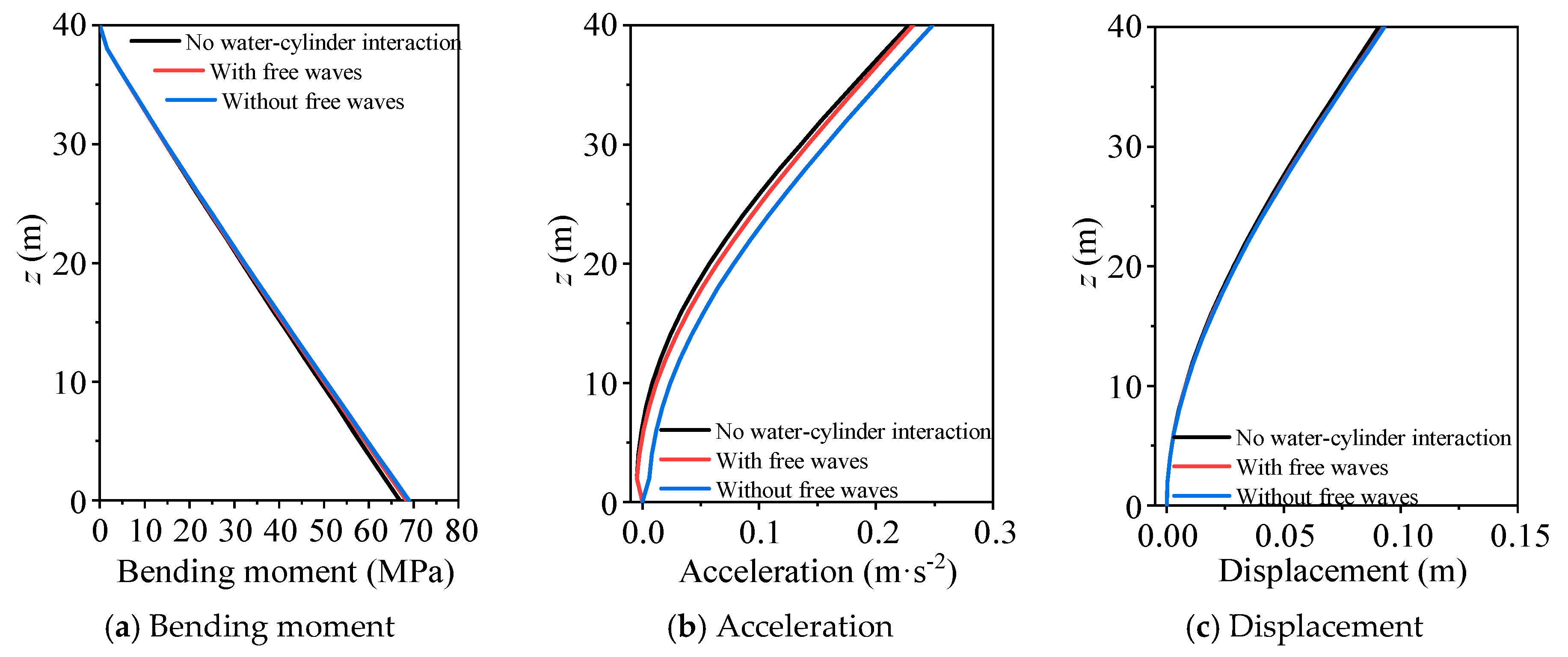
The dynamic responses of the cylinder with the first-order natural vibration period of the cylinder Ts = 3.5 s and mass ratio Rm = 12.83 are first studied, where the wave periods are set as 7 s and 8 s. Figure 9 shows the time history of the displacement on the cylinder head for a damping ratio of 0 and 0.02. Figure 10 and Figure 11 show the maximum bending moment, acceleration, and displacement along the cylinder length with wave periods equal to 3.7 s and 8 s, respectively, where the damping ratio is 0.01. It can be seen that the effects of water–cylinder interaction and free surface waves on the wave responses of the cylinder significantly decrease as the damping ratio of the cylinder increases. Notably, water–cylinder interaction can significantly increase the wave response of the cylinder when its natural frequencies are close to the wave periods. In contrast, this influence is minimal when the wave period is far from the cylinder’s natural vibration periods. Moreover, the added damping resulting from the free surface waves can significantly decrease the wave responses of the cylinders when the effects of water–cylinder interaction are large.
A quantitative analysis is further conducted to study the effects of water–cylinder interaction on the dynamic responses of the cylinder, varied with wave period and the first-order natural vibration period of the cylinder (mass ratio). Two dimensionless coefficients, including Ru1 and RM1, are defined as follows:
R u 1 = ( u 2 u 1 ) u 1 % , R M 1 = ( M 2 M 1 ) M 1 %
where u1 and M1 denote the peak top displacement and base bending moment of the cylinder without considering water–cylinder interaction; u2 and M2 denote the peak displacement of the cylinder top and bending moment at the base of the cylinder, considering the boundary condition of free surface waves. Figure 12 and Figure 13 show the variation of Ru1 and RM1 with wave period for different mass ratios and damping ratios, respectively. Generally, the water–cylinder interaction tends to increase the displacement and bending moment of the cylinder, and this influence diminishes as the damping ratio increases. However, when the wave period is close to the cylinder’s natural vibration period, water–cylinder interaction can significantly reduce the dynamic responses. It can also be seen that the effects of water–cylinder interaction on the dynamic responses of the cylinder become negligible when the wave period exceeds 5 s.
Finally, the effects of the boundary condition of free surface waves on the dynamic responses of the cylinder are quantitatively studied, where three dimensionless coefficients, including Ru2 and RM2, are defined as the following:
R u 2 = ( u 3 u 2 ) u 2 % , R M 2 = ( M 3 M 2 ) M 2 %
where u3 and M3 denote the peak top displacement and bending moment of the cylinder without considering the boundary condition of free surface waves. Figure 14 and Figure 15 show the variation of Ru2 and RM2 with wave period for different mass ratios and damping ratios, respectively. Generally, the boundary condition of free surface waves tends to reduce the wave-induced dynamic responses of the cylinder due to the added damping effect, while this influence is less than 5%. However, the boundary condition of free surface waves can significantly decrease the dynamic responses of the cylinder when the wave period is close to the natural vibration period of the cylinder.

5.3. Earthquake Loading

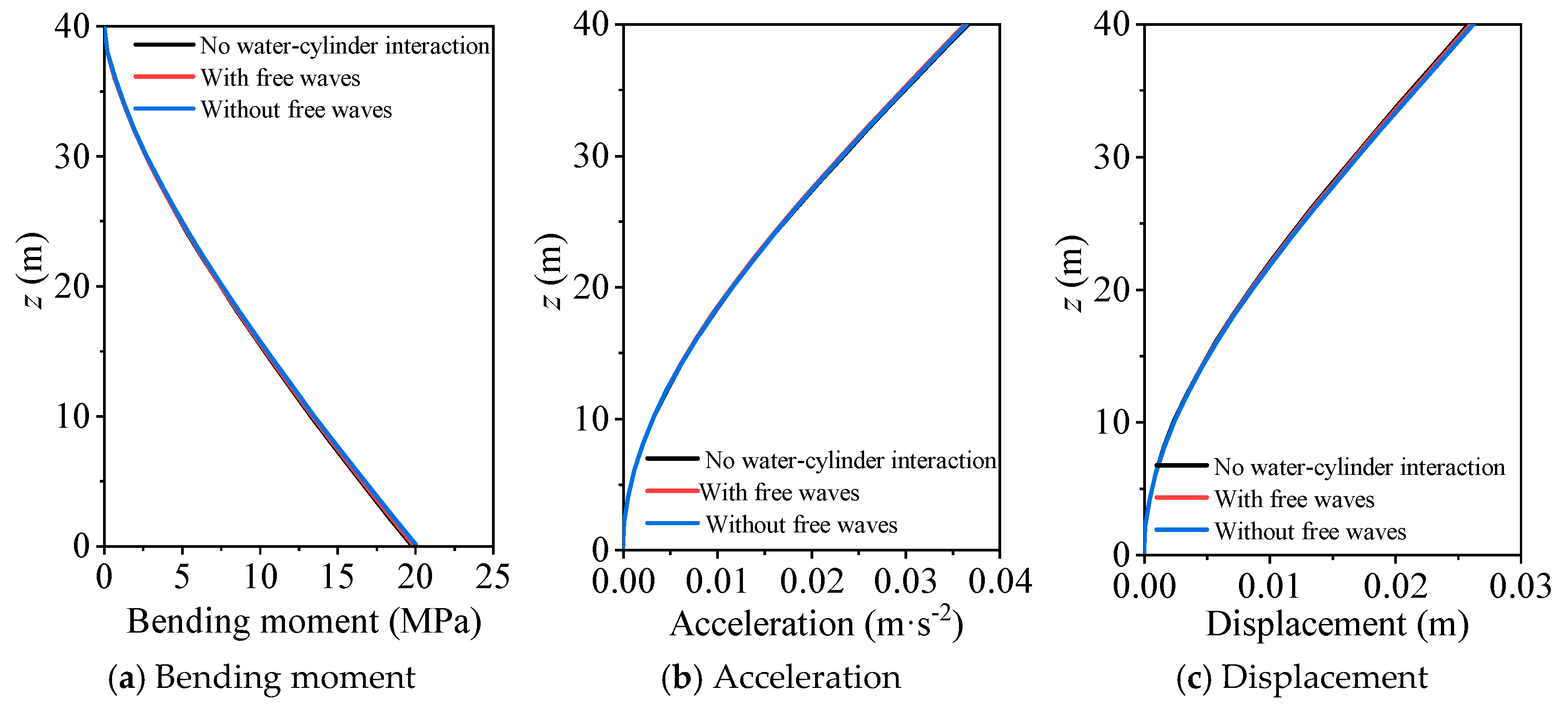
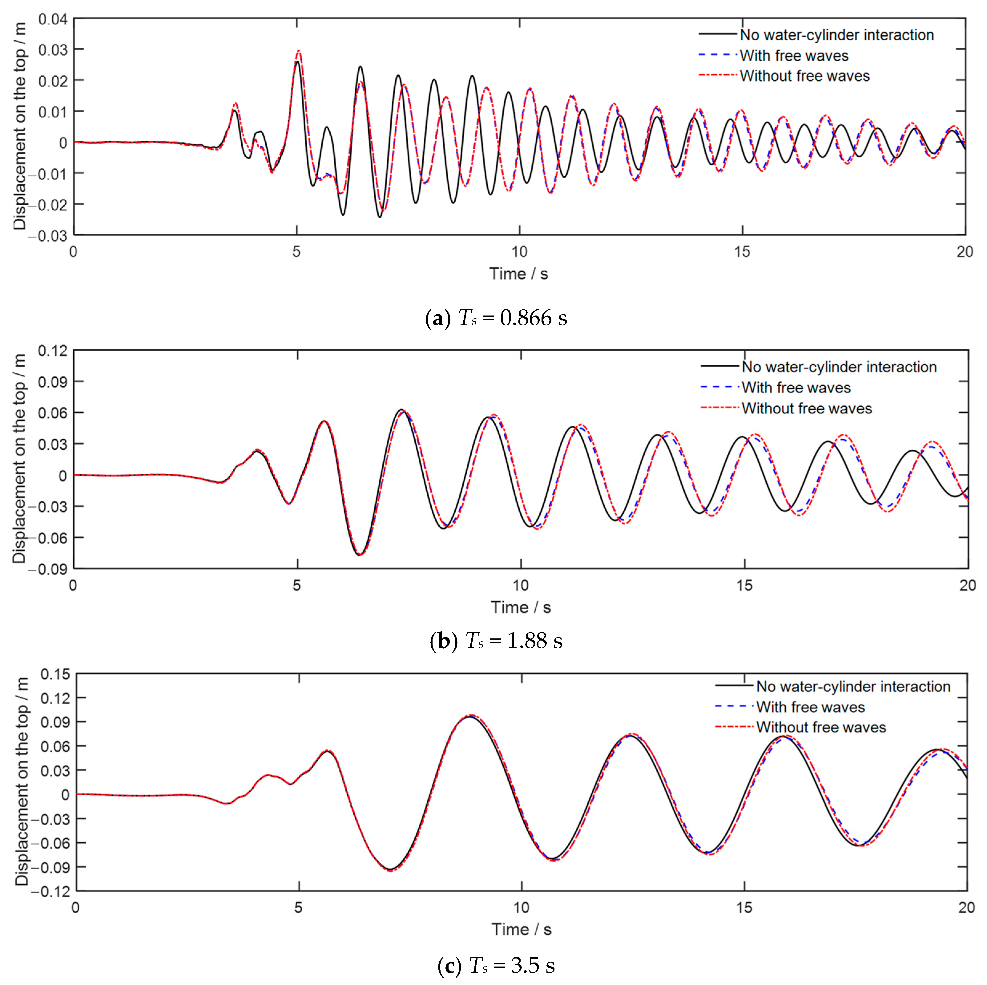
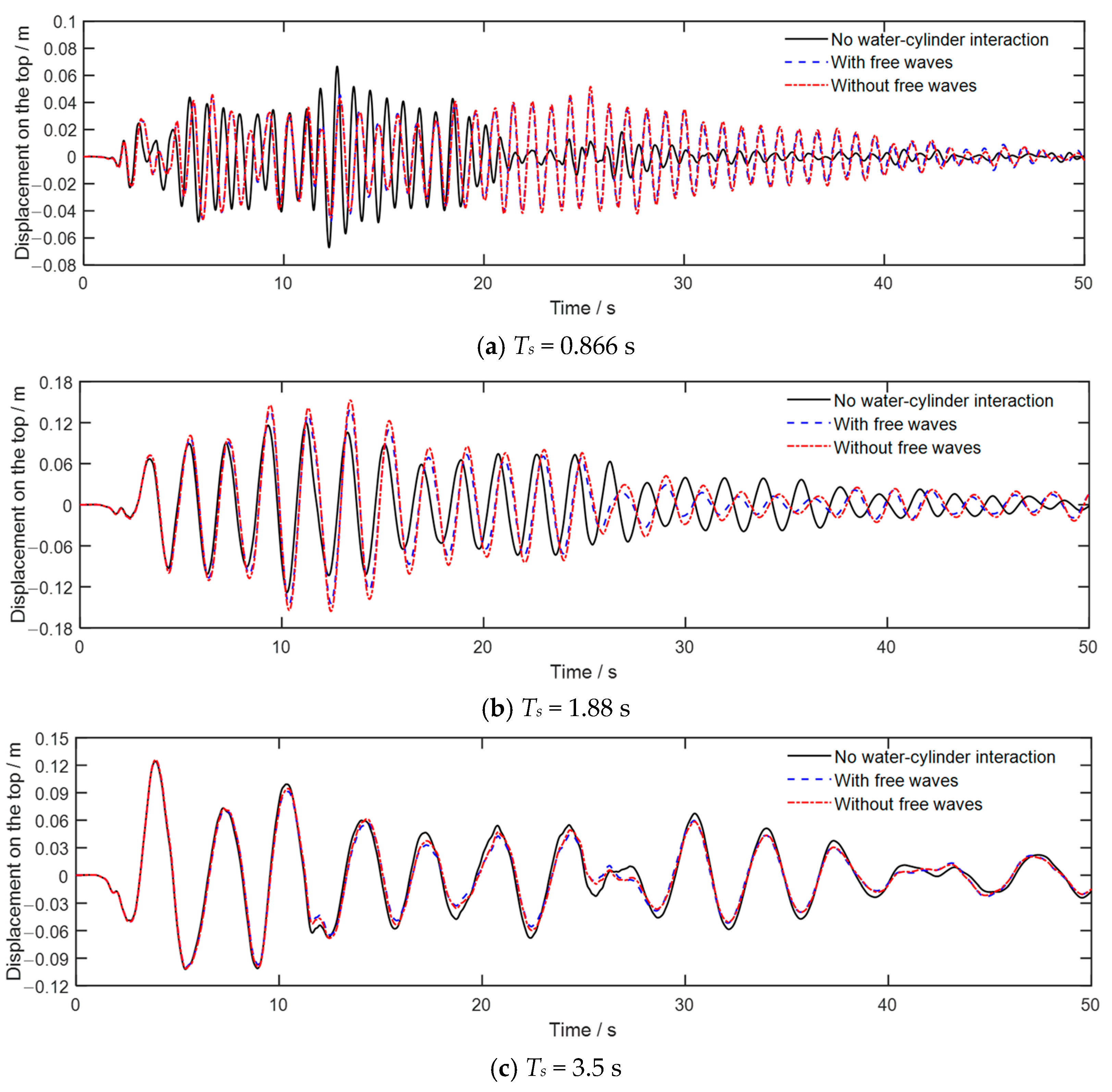
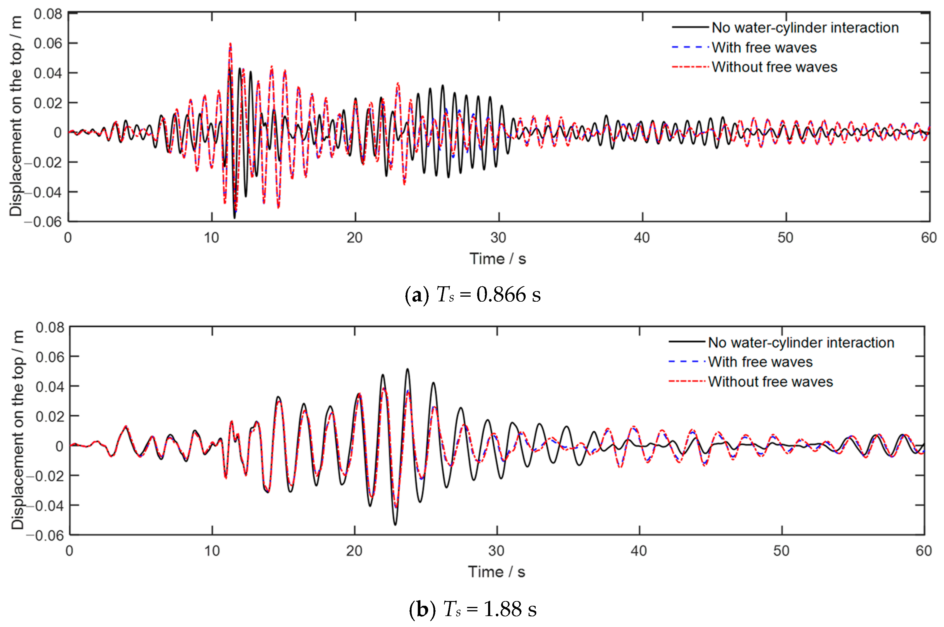
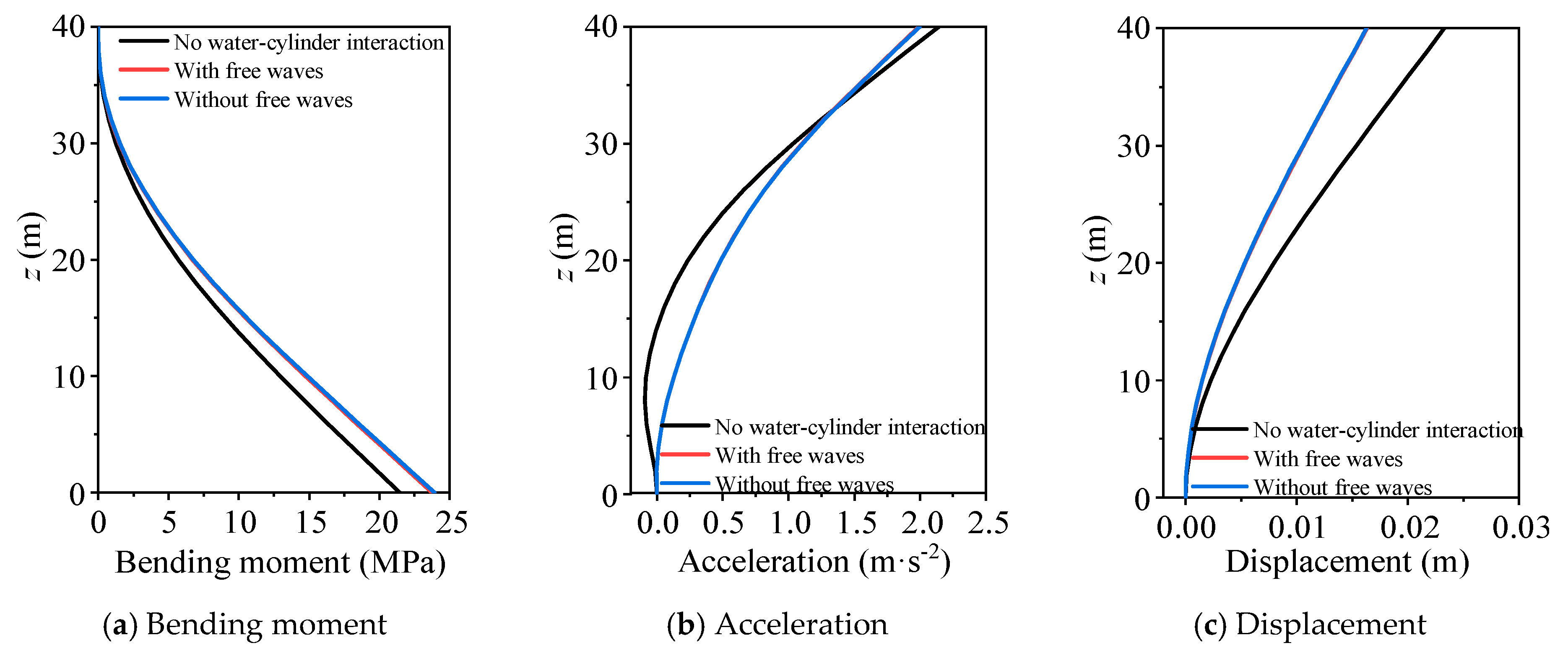
Figure 16, Figure 17 and Figure 18 show the time history of the displacements at the cylinder head for first-order natural vibration periods of Ts= 0.866 s, 1.88 s, and 3.5 s (Rm = 2.5, 5.0, and 12.83) under Chichi, El-Centro, and Christchurch earthquakes, respectively, with the damping ratio set as 0.02. Figure 19 and Figure 20 show the maximum bending moment, acceleration, and displacement along the length of the cylinder for the Christchurch wave, for mass ratios of 2.5 and 12.83, respectively. It can be seen that the effects of water–cylinder interaction on the seismic responses of the cylinder significantly decrease as the natural vibration period of the cylinder decreases. The water–cylinder interaction may either amplify or reduce the peak responses of the cylinder, depending closely on the frequency spectrum of the seismic wave, as well as the cylinder’s natural vibration period and damping ratio. Additionally, the water–cylinder interaction tends to increase the natural vibration period of the cylinder, whereas the free surface waves have little influence on the natural vibration period. It can also be seen that the boundary condition of free surface waves has minimal influence on the seismic responses of the cylinder in the case of ξ = 0.02.
A quantitative analysis is furtherly conducted to study the effects of water–cylinder interaction and boundary condition of free surface waves on the seismic responses of the cylinder varied with mass ratio. Figure 21 and Figure 22 show the variation of Ru1 and RM1 with mass ratio and damping ratio, respectively. It can be seen that water–cylinder interaction can significantly influence the seismic responses of the cylinder, especially when the mass ratio is small. Generally, the effects of water–cylinder interaction decrease with increasing damping ratio. Figure 23 and Figure 24 show the variation of Ru2 and RM2 with mass ratio for different damping ratios, respectively. It can be seen that the boundary condition of free surface waves reduces the seismic responses of the cylinder due to the added damping effect, and this influence significantly decreases as the damping ratio increases. Moreover, the effect of the boundary condition of free surface waves on the bending moment is considerably larger than that on displacement, and this influence on the bending moment is less than 5% when the damping ratio is larger than 0.02. In general, the effects of the boundary condition of free surface waves on the seismic responses of the cylinder can be considered negligible when the damping ratio of the cylinder is larger than 0.02.

6. Conclusions

In the present study, a high-precision and efficient time-domain substructure method is developed to simulate water–cylinder interaction considering the boundary condition of free surface waves. The frequency-dependent added mass and added damping are equivalent as a spring-dashpot-mass model in the time domain, which is stable, efficient and can be seamlessly coupled with the explicit finite element method. The proposed method is further applied to evaluate the effects of added mass and damping on the dynamic responses of the circular cylinder subjected to wave and earthquake loads. From all the results presented in this study, the main conclusions are summarized as follows:
  • The proposed time-domain substructure method agrees well with the frequency-domain FEM, while the calculation efficiency is improved by approximately two orders of magnitude.
  • Water–cylinder interaction generally increases the displacement and bending moment of the cylinder under wave loads, while it can markedly decrease the dynamic responses when the wave period is close to the natural vibration period. The effects of water–cylinder interaction can be neglected for wave periods greater than 5 s.
  • The boundary condition of free surface waves has a negligible effect (<5%) on wave responses of the cylinder in most cases, while its added damping effect can significantly decrease the dynamic responses of the cylinder when the wave period is near the natural vibration period of the cylinder.
  • The water–cylinder interaction can significantly influence the seismic responses of the cylinder, especially when the mass ratio is small. Generally, the effects of water–cylinder interaction decrease as the damping ratio increases.
  • The boundary condition of free surface waves can decrease the seismic responses of the cylinder, and this influence significantly decreases as the damping ratio increases. In general, this effect can be neglected when the damping ratio of the cylinder is larger than 0.02.
  • Water–cylinder interaction tends to increase the natural vibration period of the cylinder, while the free surface waves have little influence on it.

Author Contributions

Conceptualization, Z.T. and X.D.; Methodology, P.W.; Software, H.F. and H.L.; Validation, H.L.; Writing—original draft, P.W.; Supervision, Z.T. and X.D. All authors have read and agreed to the published version of the manuscript.

Funding

This work is supported by the Beijing Natural Science Foundation (JQ24050) and the National Natural Science Foundation of China (52478479).

Data Availability Statement

The original contributions presented in this study are included in the article. Further inquiries can be directed at the corresponding author.

Conflicts of Interest

The authors declare no conflict of interest.

References

  1. Chaudhari, V.; Somala, S.N. Fragility of offshore wind turbines variation with pulse-period and amplitude: Directivity and Fling step. Structures 2022, 41, 66–76. [Google Scholar] [CrossRef]
  2. Bai, X.Y.; Jiang, H.; Song, G.S.; Li, X. Extreme responses of sea-crossing bridges subjected to offshore ground motion and correlated extreme wind and wave. Ocean Eng. 2022, 247, 110710. [Google Scholar] [CrossRef]
  3. Ur Rehman, S.S.; Cui, Y.; Wang, Z.X.; Ang, Y. Performance assessment of pile supported wharves with seismic isolation system considering pile-soil interaction. Ocean Eng. 2024, 312, 119219. [Google Scholar] [CrossRef]
  4. Han, R.P.S.; Xu, H. A simple and accurate added mass model for hydrodynamic fluid-structure interaction analysis. J. Frankl. Inst. 1996, 333, 929–945. [Google Scholar] [CrossRef]
  5. Liaw, C.Y.; Chopra, A.K. Dynamics of towers surrounded by water. Earthq. Eng. Struct. Dyn. 1974, 3, 33–49. [Google Scholar] [CrossRef]
  6. Wei, K.; Yuan, W.C.; Bouaanani, N. Experimental and numerical assessment of the three dimensional modal dynamic response of bridge pile foundations submerged in water. J. Bridge Eng. 2013, 18, 1032–1041. [Google Scholar] [CrossRef]
  7. Du, X.; Wang, P.; Zhao, M. Simplified formula of hydrodynamic pressure on circular bridge piers in the time domain. Ocean Eng. 2014, 85, 44–53. [Google Scholar] [CrossRef]
  8. Li, Q.; Yang, W.L. An improved method of hydrodynamic pressure calculation for circular hollow piers in deep water under earthquake. Ocean Eng. 2013, 72, 241–256. [Google Scholar] [CrossRef]
  9. Jiang, H.; Wang, B.; Bai, X.; Zeng, C.; Zhang, H. Simplified expression of hydrodynamic pressure on deep water cylindrical bridge piers during earthquakes. Bridge Eng. 2017, 22, 04017014. [Google Scholar] [CrossRef]
  10. Wang, P.; Zhao, M.; Du, X. Analytical solution and simplified formula for earthquake induced hydrodynamic pressure on elliptical hollow cylinders in water. Ocean Eng. 2018, 148, 149–160. [Google Scholar] [CrossRef]
  11. Wang, P.; Zhao, M.; Du, X. Simplified formula for earthquake-induced hydrodynamic pressure on round-ended and rectangular cylinders surrounded by water. J. Eng. Mech. ASCE 2019, 145, 04018137. [Google Scholar] [CrossRef]
  12. Wang, P.; Zhao, M.; Du, X.; Liu, J.; Chen, J. Simplified evaluation of earthquake-induced hydrodynamic pressure on circular tapered cylinders surrounded by water. Ocean Eng. 2018, 164, 105–113. [Google Scholar] [CrossRef]
  13. Wang, P.G.; Wang, X.J.; Zhao, M.; Cheng, X.L.; Du, X.L. A numerical model for earthquake-induced hydrodynamic forces and wave forces on inclined circular cylinder. Ocean Eng. 2020, 207, 107382. [Google Scholar] [CrossRef]
  14. Morison, J.R.; O’Brien, M.P.; Johnson, J.W.; Schaff, S.A. The force exerted by surface waves on piles. AIME Pet. Trans. 1950, 189, 149–154. [Google Scholar] [CrossRef]
  15. MacCamy, R.C.; Fuchs, R.A. Wave Forces on Piles: A Diffraction Theory; Report No.TM-69; U.S. Army Corps of Engineers, Beach Erosion Board: Washington, DC, USA, 1954. [Google Scholar]
  16. Fish, P.R.; Dean, R.B.; Heaf, N.J. Fluid-structure interaction in Morison's equation for the design of offshore structures. Eng. Struct. 1980, 2, 15–26. [Google Scholar] [CrossRef]
  17. Penzien, J.; Kaul, M.K. Response of offshore towers to strong motion earthquakes. Earthq. Eng. Struct. Dyn. 1972, 1, 55–68. [Google Scholar] [CrossRef]
  18. Song, B.; Zheng, F.; Li, Y. Study on a simplified calculation method for hydrodynamic pressure to slender structures under earthquakes. J. Earthq. Eng. 2013, 17, 720–735. [Google Scholar] [CrossRef]
  19. Jian, Y.; Zhan, J.; Zhu, Q. Short crested wave-current forces around a large vertical circular cylinder. Eur. J. Mech. B-Fluids 2008, 27, 346–360. [Google Scholar] [CrossRef]
  20. Wang, P.G.; Zhao, M.; Du, X.L.; Liu, J.B. Dynamic response of bridge pier under combined earthquake and wave-current action. J. Bridge Eng. 2019, 24, 04019095. [Google Scholar] [CrossRef]
  21. Wang, P.G.; Zhao, M.; Du, X.L.; Liu, J.B. Analytical solution for the short-crested wave diffraction by an elliptical cylinder. Eur. J. Mech. B-Fluids 2019, 74, 399–409. [Google Scholar] [CrossRef]
  22. Newman, J.N. Marine Hydrodynamics; MIT Press: Cambridge, MA, USA, 2018. [Google Scholar]
  23. Molin, B. Offshore Structure Hydrodynamics; Cambridge University Press: Cambridge, UK, 2023. [Google Scholar]
  24. Rahman, M.; Bhatta, D.D. Evaluation of added mass and damping coefficients of an osciallating circular cylinder. Appl. Math. Model. 1993, 17, 70–79. [Google Scholar] [CrossRef]
  25. Wolf, J.P. Consistent lumped-parameter models for unbounded soil: Physical representation. Earthq. Eng. Struct. Dyn. 1991, 20, 11–32. [Google Scholar] [CrossRef]
  26. Bubnicki, Z. Modern Control Theory; Springer: Berlin/Heidelberg, Germany, 2005. [Google Scholar]
  27. Tang, Z.Y.; Li, X.; Wang, Z.Y. Stable parameters identification for rational approximation of single-degree-of-freedom frequency response function of semi-infinite medium. Int. J. Numer. Methods Eng. 2023, 124, 5596–5615. [Google Scholar] [CrossRef]
  28. Wang, P.G.; Zhang, W.Q.; Xu, H.B.; Zhao, M.; Du, X.L. A high-accuracy substructure method in the time domain for simulating pile-soil dynamic interaction in horizontal vibration. Comput. Geotech. 2021, 140, 104479. [Google Scholar] [CrossRef]
  29. Wang, P.G.; Zhao, M.; Li, H.F.; Du, X.L. An accurate and efficient time-domain model for simulating water-cylinder dynamic interaction during earthquakes. Eng. Struct. 2018, 166, 263–273. [Google Scholar] [CrossRef]
  30. Zhao, M.; Du, X.; Liu, J.; Li, H. Explicit finite element artificial boundary scheme for transient scalar waves in two-dimensional unbounded waveguide. Int. J. Numer. Methods Eng. 2011, 87, 1074–1104. [Google Scholar] [CrossRef]
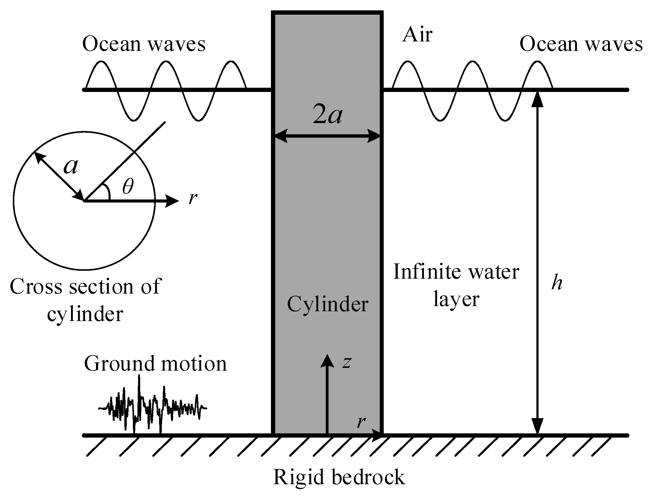
Figure 1. A circular cylinder surrounding by water overlying rigid bedrock.
Jmse 13 01814 g001
Figure 2. Typical frequency-dependent added mass and damping coefficients for water–cylinder interaction.
Jmse 13 01814 g002
Figure 3. Schematic of the hybrid identification method combining Genetic Algorithm (GA) and Sequential Quadratic Programming (SQP).
Jmse 13 01814 g003
Figure 4. Comparison of the magnitude and phase of dynamic stiffness at different vertical positions with those of the fitted rational approximation.
Jmse 13 01814 g004
Figure 5. The spring-dashpot-mass model.
Jmse 13 01814 g005
Figure 6. Acceleration curves of seismic waves: (a) time history; and (b) amplitude of the frequency spectrum.
Jmse 13 01814 g006
Figure 7. The comparison of proposed method and frequency-domain FEM under wave load with wave period 8 s.
Jmse 13 01814 g007
Figure 8. The comparison of proposed method and frequency-domain FEM under El-Centro seismic wave.
Jmse 13 01814 g008
Figure 9. Time history of the displacement on the cylinder head with different wave period and damping ratio: (a) damping ratio = 0, wave period = 3.7 s; (b) damping ratio = 0.02, wave period = 3.70 s; (c) damping ratio = 0, wave period = 8 s; and (d) damping ratio = 0.02, wave period = 8 s.
Jmse 13 01814 g009
Figure 10. The maximum responses along the length of the cylinder with wave period equal to 3.7 s: (a) peak bending moment response; (b) peak acceleration response; and (c) peak displacement response.
Jmse 13 01814 g010
Figure 11. The maximum responses along the length of the cylinder with wave period equal to 8 s: (a) peak bending moment response; (b) peak acceleration response; and (c) peak displacement response.
Jmse 13 01814 g011
Figure 12. The dimensionless coefficient Ru1 varied with wave period for different mass ratio and damping ratio: (a) damping ratio = 0.005; (b) damping ratio = 0.01; (c) damping ratio = 0.02; and (d) damping ratio = 0.05.
Jmse 13 01814 g012
Figure 13. The dimensionless coefficient RM1 varied with wave period for different mass ratio and damping ratio: (a) damping ratio = 0.005; (b) damping ratio = 0.01; (c) damping ratio = 0.02; and (d) damping ratio = 0.05.
Jmse 13 01814 g013
Figure 14. The dimensionless coefficient Ru2 varied with wave period for different mass ratio and damping ratio: (a) damping ratio = 0.005; (b) damping ratio = 0.01; (c) damping ratio = 0.02; and (d) damping ratio = 0.05.
Jmse 13 01814 g014
Figure 15. The dimensionless coefficient RM2 varied with wave period for different mass ratio and damping ratio: (a) damping ratio = 0.005; (b) damping ratio = 0.01; (c) damping ratio = 0.02; and (d) damping ratio = 0.05.
Jmse 13 01814 g015
Figure 16. Time history of the displacement on the cylinder head under Christchurch seismic wave: (a) the first-order natural vibration period of the cylinder = 0.866 s; (b) the first-order natural vibration period of the cylinder = 1.88 s; and (c) the first-order natural vibration period of the cylinder = 3.5 s.
Jmse 13 01814 g016
Figure 17. Time history of the displacement on the cylinder head under El-Centro seismic wave: (a) the first-order natural vibration period of the cylinder = 0.866 s; (b) the first-order natural vibration period of the cylinder = 1.88 s; and (c) the first-order natural vibration period of the cylinder = 3.5 s.
Jmse 13 01814 g017
Figure 18. Time history of the displacement on the cylinder head under Chichi seismic wave: (a) the first-order natural vibration period of the cylinder = 0.866 s; (b) the first-order natural vibration period of the cylinder = 1.88 s; and (c) the first-order natural vibration period of the cylinder = 3.5 s.
Jmse 13 01814 g018aJmse 13 01814 g018b
Figure 19. The maximum responses along the length of the cylinder for Christchurch wave with mass ratio equal to 2.5: (a) peak bending moment response; (b) peak acceleration response; and (c) peak displacement response.
Jmse 13 01814 g019
Figure 20. The maximum responses along the length of the cylinder for Christchurch wave with mass ratio equal to 12.83: (a) peak bending moment response; (b) peak acceleration response; and (c) peak displacement response.
Jmse 13 01814 g020
Figure 21. The dimensionless coefficient Ru1 varied with mass ratio for different damping ratio: (a) damping ratio = 0.005; (b) damping ratio = 0.01; (c) damping ratio = 0.02; and (d) damping ratio = 0.05.
Jmse 13 01814 g021
Figure 22. The dimensionless coefficient RM1 varied with mass ratio for different damping ratio: (a) damping ratio = 0.005; (b) damping ratio = 0.01; (c) damping ratio = 0.02; and (d) damping ratio = 0.05.
Jmse 13 01814 g022
Figure 23. The dimensionless coefficient Ru2 varied with mass ratio for different damping ratio: (a) damping ratio = 0.005; (b) damping ratio = 0.01; (c) damping ratio = 0.02; and (d) damping ratio = 0.05.
Jmse 13 01814 g023
Figure 24. The dimensionless coefficient RM2 varied with mass ratio for different damping ratio: (a) damping ratio = 0.005; (b) damping ratio = 0.01; (c) damping ratio = 0.02; and (d) damping ratio = 0.05.
Jmse 13 01814 g024
Table 1. The simulation parameters used in the present study.
ParameterValue
Water density1000 kg/m3
Water depth40 m
Radius of the cylinder2 m
Elastic modulus of the cylinder30 GPa
Density of the cylinder2500 kg/m3
Peak acceleration of seismic waves0.1 g
Wave height4 m
Table 2. The simulated cases for the wave and earthquake loads.
CaseMass RatioDamping Ratio
Wave load: wave period set as 3 s to 10 s2.5, 5.08,
7.66, 12.82
0.0, 0.005, 0.01,
0.02, 0.05
Seismic waves: Chichi, El-Centro, Christchurch2.5 to 12.820.0, 0.005, 0.01,
0.02, 0.05
Table 3. Convergence test for time step sizes.
Time Step (s)Displacement (m)Acceleration (m·s−2)
0.050.01743−0.01802
0.020.01738−0.01743
0.010.01737−0.01733
Table 4. Mesh independence verification.
Mesh Size (m)Displacement (m)Acceleration (m·s−2)
40.01742−0.01597
20.01737−0.01734
10.01732−0.01735
Disclaimer/Publisher’s Note: The statements, opinions and data contained in all publications are solely those of the individual author(s) and contributor(s) and not of MDPI and/or the editor(s). MDPI and/or the editor(s) disclaim responsibility for any injury to people or property resulting from any ideas, methods, instructions or products referred to in the content.