Article

Ship Motion Control Methods in Confined and Curved Waterways Combining Good Seamanship

1
School of Navigation, Wuhan University of Technology, Wuhan 430063, China
2
Hubei Key Laboratory of Inland Shipping Technology, Wuhan 430063, China
*
Author to whom correspondence should be addressed.
J. Mar. Sci. Eng. 2025, 13(9), 1800; https://doi.org/10.3390/jmse13091800
Submission received: 20 August 2025 / Revised: 12 September 2025 / Accepted: 16 September 2025 / Published: 17 September 2025

Abstract

For the motion control of ships in confined and curved waterways, from broad coastal channels to narrow river bends, conventional methods often struggle to ensure both tracking accuracy and navigational safety. A key deficiency is the inability of standard algorithms to incorporate the nuanced principles of good seamanship. To address this, a novel, hierarchical adaptive control framework is proposed. The core novelty of this framework lies in its versatile and adaptive guidance rules, which embed maritime practice into the control loop for different navigating scenarios. In general maritime channels with wind and current, these rules function to ensure robust, high-fidelity route tracking. For the most challenging inland river curved channels, it is further enhanced to generate a strategic, non-centerline trajectory that replicates the crucial inland navigational practice of “holding high and taking low”. This is complemented by a reinforcement learning-based strategy at the control layer, which performs real-time tuning of PID gains to adapt to the vessel’s dynamics. The framework’s dual capabilities were systematically validated. The core adaptive algorithms proved effective for robust control in curved channels under wind and current disturbances. Furthermore, the full framework, including the seamanship-informed strategy, demonstrated superior performance in the most complex inland river scenarios. Compared to a conventional controller, the proposed method reduced the peak cross-track error by over 40% and increased the minimum safety margin from the bank by more than 49% under a strong 3 m/s cross-current. An effective solution for motion control is thus provided, bridging the gap between modern control theory and the context-dependent expertise of practical pilotage.

1. Introduction

Inland waterway transport and coastal shipping are vital components of the global logistics system, playing an indispensable role in promoting economic development. As global trade expands and vessels become larger, the increasing traffic density and complexity in confined and curved waterways make advanced vessel control essential. These demanding environments—ranging from broad coastal channels and harbor approaches to narrow, winding inland rivers—present some of the most common and challenging segments in maritime navigation [1]. The narrow boundaries, varying curvatures, and complex hydrodynamics in these segments place extreme demands on maneuvering precision and safety, contributing to a significant portion of maritime accidents [2]. Consequently, the control of vessels within these restricted waters has become a critical impediment to the progress of ship automation and autonomous navigation. While numerous automated control methods have been developed, a significant discrepancy persists between current control methodologies and proven maritime practice for navigating bends—channel segments characterized by varying curvatures, restricted widths, and complex, asymmetric hydrodynamic forces. This gap means that existing automated systems often fail to incorporate the principles of good seamanship that are contextually adapted to different types of bends. This leaves the vessel vulnerable to risks such as grounding or allision with the bank. Bridging this gap between control theory and practical expertise is therefore of critical importance. Overcoming this challenge is not only essential for the development of advanced autopilots for all types of confined waters, but will also lay a crucial foundation for the future of robust autonomous navigation in both maritime and inland environments.
Vessel motion control, particularly route-tracking control, has long been a central research topic in the maritime field. The core challenge lies in designing a control system that can precisely follow a predefined route while effectively rejecting internal and external uncertainties [3]. Existing research typically approaches this problem using a hierarchical architecture composed of a high-level Guidance system and a low-level Control system [4]. The guidance layer is responsible for generating a desired heading or course to steer the vessel towards the route [5]. while the control layer manipulates the actuators, such as the rudder, to achieve that command [6].
At the guidance level, the Line-of-Sight (LOS) algorithm is the most widely adopted baseline method due to its intuitive principle and computational simplicity [7,8,9]. This algorithm emulates the behavior of a human helmsman by generating a desired heading based on a lookahead vector aimed at a future point on the route. However, a significant body of research has highlighted a fundamental limitation of the conventional LOS guidance law: in the presence of persistent external disturbances, such as lateral currents, the system exhibits an ineliminable steady-state cross-track error, severely compromising navigational accuracy [10,11,12]. To address this issue, various improved schemes have been proposed. Among the most prominent is Integral LOS (ILOS) [13], which introduces an integral term of the cross-track error into the guidance law to estimate and compensate for the drift angle induced by environmental forces, thereby effectively eliminating the steady-state error. The development of LOS guidance has evolved through multiple technical iterations. Oh et al. [14] pioneered MPC-LOS integration to address constrained route tracking, while Fossen [15] introduced adaptive ILOS to counteract time-varying ocean currents. Subsequent innovations include Fossen’s ALOS [16] for drift-angle estimation, Liu’s PLOS [17] and ELOS [18] for accelerated drift compensation (constrained in time-varying scenarios), and Wang’s finite-time LOS [19] enabling rapid estimation of arbitrary side-slip angles. Concurrently, Zheng [20] and Nie [21] developed adaptive integral LOS with proven bounded stability against current disturbances.
Beyond integral-based approaches, some researchers have leveraged the inherent robustness of Sliding Mode Control (SMC) to design Sliding Mode LOS guidance laws, enhancing the system’s resilience against uncertainties [22,23]. Based on this, DVS guidance, LVS guidance and virtual guidance have also been developed and perfected [24,25]. Other notable guidance paradigms include the Serret-Frenet coordinate framework, which simplifies kinematic modeling by transforming navigation errors [26,27], and the dynamic virtual ship concept, which redefines route-following as a virtual vessel tracking problem [28]. Despite these advances, improved methods often introduce new challenges, such as integral windup in ILOS or the chattering phenomenon in SMC. This indicates that designing a guidance law that is both effective at disturbance rejection and possesses excellent dynamic performance and adaptability remains a subject of ongoing research.
At the control level, early efforts focused on employing intelligent techniques such as Fuzzy Logic and Neural Networks for adaptive proportional-integral-derivative (PID) tuning [29]. The PID controller remains the dominant algorithm for applications like ship heading control, owing to its simple structure, proven stability, and reliability [30,31]. However, the performance of a PID controller is highly dependent on the tuning of its gains. A ship is a complex, time-varying nonlinear system whose dynamics change with speed, loading conditions, and water depth. A set of fixed PID gains, typically tuned offline via methods like Ziegler-Nichols, can rarely maintain optimal performance across all operating conditions, exhibiting poor adaptability. To achieve self-tuning capabilities, extensive research has been conducted. Fossen [32] proposed a PID coefficient self-tuning method based on second-order system characteristics, while Dlabač [33] used the PSO algorithm for a fast and optimal design of the PID parameters, and the experimental results verified the feasibility of the methods.
However, this type of passive anti-disturbance strategy has a significant lag in response to disturbances, and usually requires a large number of datasets for training, making it difficult to meet the real-time demands of control [34,35,36]. By linearizing the controller and the Extended State Observer (ESO), the Linear ADRC (LADRC) technique was developed and successfully applied to the study of autonomous berthing of ships [37]. Other control algorithms, such as sliding mode control, can overcome the instability of the system, but its jitter problem still needs to be further solved [38]. Reinforcement learning, deep learning and other advanced control algorithms, although innovative research has been carried out theoretically, their application in ship route tracking is yet to be further verified.
To achieve robust motion control in confined and curved waterways, a unified framework is required that can both compensate for external disturbances and adapt to internal model uncertainty. Addressing this challenge, a novel hierarchical control architecture is proposed. This framework forms a “dual adaptive” system by synergistically combining a context-adaptive guidance rules rooted in maritime practice with a reinforcement learning-based control strategy. The main contributions of this research are as follows:
(1)
A Hierarchical, Decoupled Control Architecture: A key contribution is the design of a two-layer framework that strategically decouples the control problem. The high-level guidance layer is responsible for strategic path generation and external disturbance rejection, while the low-level control layer adapts to internal model uncertainty, enabling robust performance across different scenarios.
(2)
A Context-Adaptive Guidance Rules Informed by Good Seamanship: A versatile guidance rules is proposed that moves beyond naive centerline tracking. It is designed to be context-adaptive, providing robust adaptive control for general maritime scenarios while being capable of embedding the specific inland navigational strategy of “holding high and taking low” (A navigation technique for maintaining safe clearance in restricted waters by holding elevated position while adjusting course at lower elevation) [39], for the most hazardous river bends. This ability to deploy situationally appropriate strategies, consistent with proven maritime practice, significantly enhances navigational safety. The law also incorporates an adaptive integral term to resolve the steady-state error of conventional LOS guidance.
(3)
Reinforcement Learning for Adaptive PID Control: At the control layer, a Double Q-learning algorithm is employed for the online, adaptive tuning of PID gains. This leverages the model-free nature of RL to enhance the controller’s adaptability to the vessel’s time-varying dynamics and model-plant mismatch, ensuring high-fidelity execution of the guidance commands.
The superiority and versatility of the proposed framework are demonstrated through comprehensive simulations that cover both maritime-like and complex inland waterway scenarios. The results confirm that the system successfully executes maneuvers informed by good seamanship, achieving high-precision tracking and superior disturbance rejection. This validates its effectiveness and practical relevance for a wide range of real-world navigation tasks in confined waters.

2. Modeling of Vessel and Curved Waterways

2.1. Current Pattern Modeling

Based on morphological and hydrodynamic analysis, the flow patterns in confined and curved waterways can be categorized into three primary types of increasing navigational complexity, representative of conditions found across both maritime and inland domains. The first and most benign type is the “flat bend”. Characterized by a uniform and gradual change in curvature (Figure 1a), this pattern yields a predictable, symmetric flow profile. It is typically found in well-dredged shipping channels or wide sea straits where navigational challenges are moderate and primarily involve baseline path tracking.
The second type, the “sharp bend”, exhibits a rapid change in curvature that generates a highly asymmetric flow field, forcing the main streamline towards one bank (Figure 1b). This pattern is characteristic of sharp turns in harbor approaches or estuaries, where strong, persistent disturbances from wind and tidal currents demand a robust control system.
The third and most complex type is the “reversing sharp bend”. This pattern, featuring a continuous series of sharp bends with alternating curvatures, represents the most hazardous conditions (Figure 1c). It is commonly found in narrow, winding inland rivers, where the upstream geometry imposes severe constraints on the downstream flow, generating a highly turbulent and unpredictable flow field.
The navigation channel chosen for this research, the “Yaozui” section, serves as a prime case study for this most challenging pattern. A key metric for quantifying this complexity is the mainstream turning angle, ω. “Reversing Sharp Bend” patterns like Yaozui are characterized by a large and rapidly changing ω, which gives rise to hazardous hydrodynamic phenomena such as “back-pressure current” and “bend-sweeping current”. The presence of these powerful and chaotic currents severely restricts the choice of a safe path, necessitating not just robust control, but also an advanced, proactive navigational strategy.

2.2. Digital Modeling of Confined and Curved Waterways

A robust digital representation of the operational environment is a prerequisite for high-fidelity path tracking in confined waterways. This is achieved by constructing a geometric model from cartographic data, such as Electronic Navigational Charts (ENCs). For control design, a complex curved channel is decomposed into a sequence of interconnected straight-line corridors. As shown in Figure 2, each corridor, Si, is defined by a four-vertex polygon {a, b, c, d} that delineates the navigable area.
A piecewise-linear reference path is then generated by connecting the centerlines of these sequential corridors. This discretization strategy reframes the continuous navigation problem into a more tractable task of tracking a series of straight-line segments. The resulting geometric constraints serve as the essential inputs for the motion controller, whose objective is to steer the vessel along this composite trajectory while remaining within the defined boundaries.
However, to accurately model the hydrodynamic forces for a high-fidelity simulation environment, it is necessary to estimate the cross-current effects, which are intrinsically linked to the channel’s continuous curvature. The piecewise-linear path, with its sharp vertices, does not directly provide this curvature information. Therefore, for the offline modeling phase, the piecewise-linear path is geometrically transformed into an equivalent continuous trajectory composed of straight lines and circular arcs. The sole purpose of this smoothing process is to calculate a representative radius of curvature R for each bend. This radius is then used to estimate the cross-current angle, which serves as a critical input for the environmental disturbance model. The path that the vessel’s controller actually tracks remains the original piecewise-linear route. The radius R of an arc connecting two adjacent segments is determined by:
R = m i n L 1 , L 2 2 sin θ / 2
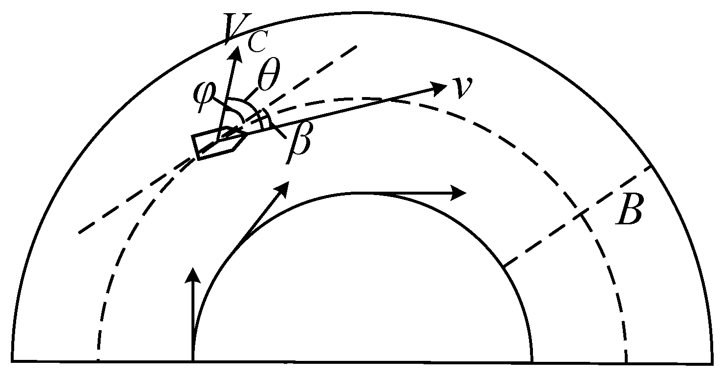
The cross-current angle—the angle between the cross-current velocity and the channel centerline—is the primary factor governing the lateral forces on the vessel. By assuming this angle to be nearly constant within a bend, the channel can be modeled as circular arcs with the cross-current flowing tangentially to the convex bank as Figure 3. Based on this idealized geometric model, the following estimation formula is derived:
cos φ = 1 C B R
where φ is the cross-current angle, R is the trajectory’s radius of curvature, B is the channel width, and C is the taking high coefficient (0 ≤ C ≤ 1). The angle β denotes the yaw angle between the ship’s axis and the channel’s tangent during the turn.
β = θ φ

2.3. Mathematical Modeling of Ship Motion

A modified three-degrees-of-freedom (3-DOF) ship motion model is employed in this study, adapted for restricted environments by incorporating the effects of wind, current [40]. The dynamics are formulated in a body-fixed coordinate system as follows:
m + m x · u ˙ + m + m y · r · v = X H + X P + X R + X E m + m y · v ˙ m + m x · r · u = Y H + Y P + Y R + X E I z z + J z z · r ˙ = N H + N P + N R + N E
In these equations, mx and my are the added masses in surge and sway; Izz and Jzz represent the moment of inertia and added moment of inertia in yaw. The terms u ˙ , v ˙ , and r ˙ denote the surge, sway, and yaw accelerations. The resultant hydrodynamic forces (X, Y) and yaw moment (N) are decomposed into contributions from the hull (H), propeller (P), and rudder (R). The term E encapsulates the forces and moments arising from external disturbances, such as wind and current. The effective thrust YP of the propeller is modeled as follows.
Y P = 1 t p T
T = ρ n p 2 D p 4 K t
t p = 0.04 + t p 0.04 u u 0       u < u 0 t p                                     u > u 0
t p = f + t p
where T is the propeller thrust and tp′ is the thrust reduction factor, a coefficient dependent on the hull form, propeller characteristics, and their geometric arrangement.
f = k t β R k t = 0.00023 γ A · L / D p 0.028 γ A = B / d 1.3 1 C b 3.1 l c b l c b = x c / L · 100 β R = β l R r V
where βR is the drift angle at the rudder center, B, d, L, Dp and xc are the ship’s breadth, draft, length, propeller diameter and longitudinal coordinates of the center of buoyancy, respectively, kt, γA, Cb, lcb and lR denote the correction coefficients, hull rectification coefficients, square coefficients, buoyancy coefficients and the angle of drift coefficients, respectively, and r and V are the rotational angular velocity, longitudinal speed, respectively.
The wind forces and moment are calculated based on empirical regression equations developed from wind tunnel tests. The total wind force coefficient, Cw, is determined as follows:
C w = 0.3935 + 3.177 sin 2 α R 1.586 sin 3 α R 0.3154 L Z G / A f + 0.04994 L Z G / A f 2 + 0.381 L Z G / A s 0.3632 L Z G / A f sin 2 α R + 0.1379 L Z G / A f 2 sin 2 α R + 3.3334 A s / L 2 A f 6 sin 2 α R + 0.453 C K sin 4 α R
CK is the distance from the center of the shape of the projected area of the ship’s side to the ship’s waterline, and the center of effort angle for the wind force, αF, is given by:
α F = s g n α R { 13.85 + 75.97 α R 19.77 α R 2 + 4.558 α R 3 20.06 C K + 37.89 L Z G / A f α R + 1113 A s / L 2 α R 56.23 L Z G / A f α R 2 1970 A s / L 2 α R 2 + 33.9 L Z G / A f α R 3 + 1212 A s / L 2 α R 3 8.21 L Z G / A f α R 4 283.1 A s / L 2 α R 4 + 0.221 L Z G / A f α R 6 + 6.17 A s / L 2 α R 6 }
The wind forces (Xw, Yw) and yaw moment (Nw) acting on the ship are then expressed as:
X w = 1 2 ρ a A f U R 2 C w x α R Y w = 1 2 ρ a A f U R 2 C w y α R N w = 1 2 ρ a A f L U R 2 C w n α R
where ρa is the air density, Af and As are the frontal and lateral projected areas of the ship above the waterline, respectively. L is the ship’s length, UR is the relative wind speed, and αR is the relative wind angle. Cwx, Cwy, and Cwn are the dimensionless wind force and moment coefficients in the surge, sway, and yaw directions. These coefficients are resolved from the total wind force coefficient Cw and the center of effort angle αF using the following relationships:
C w x = C w sin α F A f 2 + A s 2 / A s C w y = C w cos α F A f 2 + A s 2 / A f C w n = 0.5 x F / L C w sin α F A f 2 + A s 2 / A s
The longitudinal position of the wind’s center of effort, xF, is calculated as:
x F / L = C K + 0.003 α R 90 °
Here, CK represents a geometric parameter related to the centroid of the lateral projected area.
The velocity parameters in the equations of motion for the maneuvering of a ship in still water are converted to the relative velocities of the ship’s hull and the current. Let the current velocity in the environment be Vc and the current direction be φ, and decompose the current velocity into transverse and longitudinal velocities in the ship-following coordinate system, denoted as:
u c = V c cos Ψ c Ψ v c = V c sin Ψ c Ψ
Then the velocity of the ship relative to the water can be expressed as:
u = u u c v = v v c

3. Ship Motion Control Methods for Confined and Curved Channels

3.1. Methodology of Control Framework

Precise path tracking for vessels in curved waterways is a significant motion control challenge. The difficulty stems from a combination of complex geometric constraints demanding high-fidelity tracking, the vessel’s inherent large-inertia and underactuated dynamics, and the critical influence of uncertainties. These uncertainties are twofold: internal model uncertainty, arising from discrepancies between the mathematical model and the physical vessel, and external disturbances, such as persistent forces from wind and currents that cause path deviation [41].
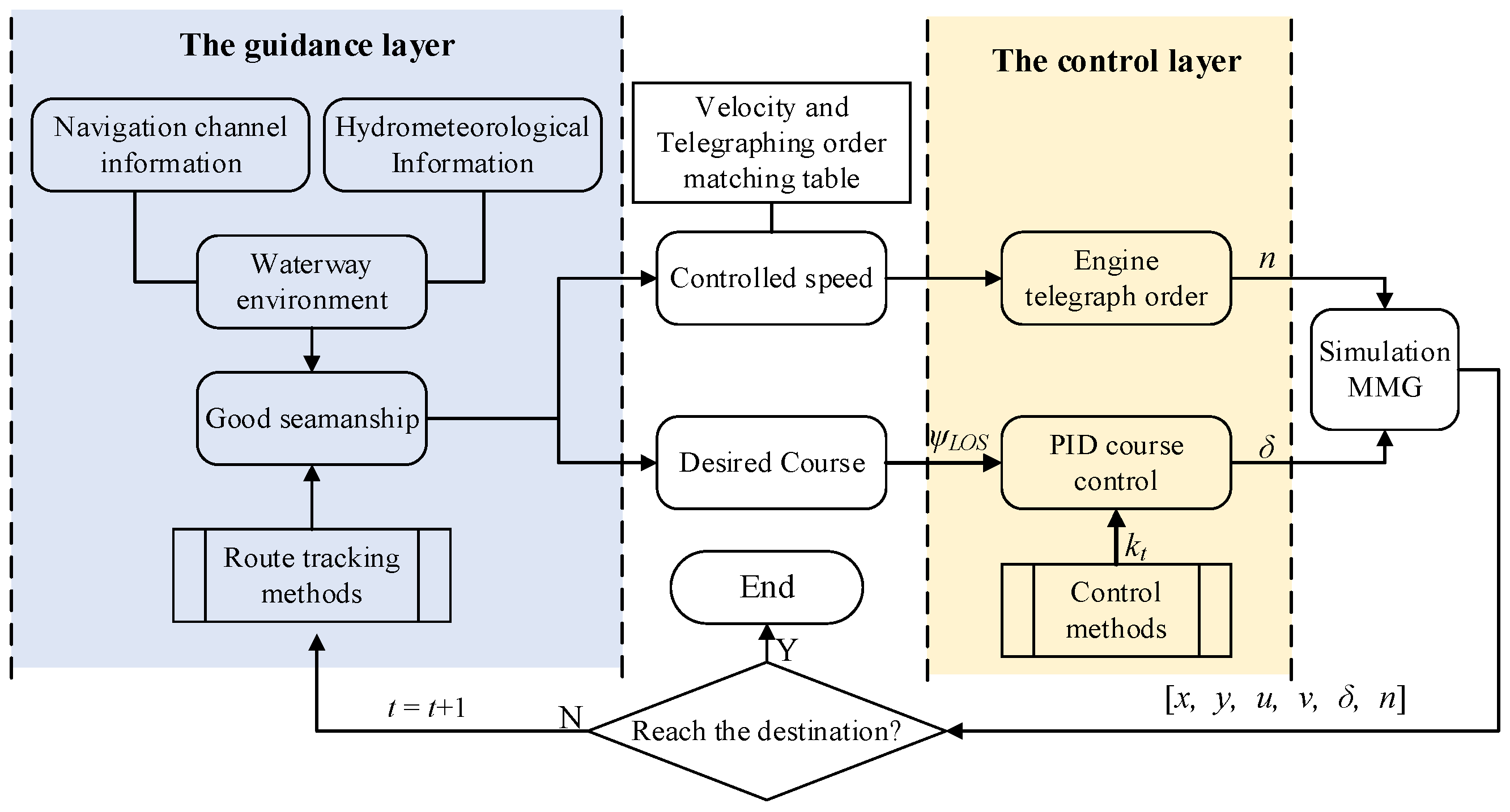
To systematically address these challenges, a hierarchical, modular control framework is proposed. As depicted in Figure 4, this framework decouples the complex path-tracking problem into two synergistic layers: a high-level guidance system and a low-level control system. The design of this framework is driven by the primary objective of ensuring navigational safety while optimizing control performance.
The high-level guidance layer is designed to compensate for external environmental disturbances, with its primary safety criterion being to keep the vessel within the navigable channel boundaries. To this end, an adaptive integral Line-of-Sight (LOS) guidance rule is employed. This rule incorporates a form of prediction: by integrating past tracking errors, it forms an online estimation of the persistent drift angle, allowing it to proactively command a corrective heading that anticipates the future effects of environmental forces, rather than merely reacting to them. This safety-oriented guidance, which can also embed navigational strategies like “holding high and taking low” generates the desired heading and velocity for the layer below.
The low-level control layer, in contrast, addresses model uncertainty and is responsible for the precise execution of the high-level commands. The core innovation here is the real-time tuning of a PID controller’s gains via Reinforcement Learning (RL), which optimizes performance based on a defined reward function. This is achieved through a more sophisticated prediction mechanism: the learned Q-value function of the RL agent acts as a predictive model, estimating the expected future cumulative reward for each potential set of PID gains. The agent’s policy is therefore inherently forward-looking, selecting the gains predicted to yield the best long-term outcome. This learning process enhances the controller’s robustness against the vessel’s time-varying dynamics and ensures the high-fidelity execution of the guidance commands.

3.2. Robust and Adaptive Guidance for Route Tracking

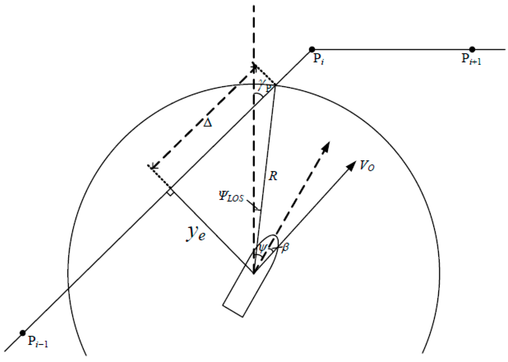
Precise path tracking in confined waterways is often achieved using an indirect strategy to avoid the implementation challenges of direct, model-based methods. This approach decouples the control problem into a well-established hierarchy of a high-level guidance system and a low-level heading controller. The guidance layer, for which a modified Line-of-Sight (LOS) algorithm is utilized, generates a real-time desired heading by steering the vessel towards a dynamic target on the reference path (Figure 5). This desired heading is then passed as a setpoint to the heading controller for execution.
The modified LOS guidance rules generate a desired heading, ψLOS, by targeting a virtual waypoint on the reference path. This waypoint is located a look-ahead distance, Δ, ahead of the vessel’s orthogonal projection onto the path. The desired heading, ψLOS, is the angle of the line connecting the vessel’s current position to this target waypoint. The cross-track error, ye(t), represents the lateral deviation from the path, whose course angle for the current segment is denoted by C p i 1 p i . The primary control objective is to eliminate this cross-track error (i.e., drive ye(t) → 0), while the secondary objective is to align the vessel’s heading with the path’s course angle for stable transit. Thus, the path-tracking control objectives can be summarized as follows:
lim t y e t 0
lim t ψ C P i P i 1
Based on this, the ship’s target heading ψLOS is calculated as follows, with γp denoting the recommended heading direction.
ψ L O S γ p tan 1 y e t Δ
The look-ahead distance, Δ, dictates the convergence rate in LOS guidance. A small Δ speeds up convergence but can cause overshoots due to the vessel’s slow dynamic response, while a large Δ is more stable but slower. A fixed Δ is therefore a compromise. To ensure consistently fast and stable path tracking, a variable look-ahead distance Δ is introduced, which adapts to the current state as defined by the following function:
f x = 0                                               x x m i n 1 2 1 cos π x x m i n x m a x x m i n       x m i n x x m a x 1                                               x x m a x
= m i n + Δ m a x Δ m i n 1 f y e t
The look-ahead distance, Δ, is dynamically adjusted using a sigmoid function, f(x), of the cross-track error, ye(t). This function smoothly maps ye(t) (within the bounds of ymin and ymax) to a value between 0 and 1. The resulting desired heading, ψLOS, is then calculated based on this adaptive Δ, the cross-track error, and the path’s course angle:
ψ L O S γ p tan 1 y e t Δ m i n + Δ m a x Δ m i n 1 f y e t
The look-ahead distance, Δ, is bounded by Δmin and Δmax. When the cross-track error is large (|ye| > ymax), Δ is minimized to Δmin to enable rapid, aggressive correction without control saturation. Conversely, when the error is small (|ye| < ymin), Δ is maximized to Δmax to ensure a smooth, stable convergence and prevent overshoot.
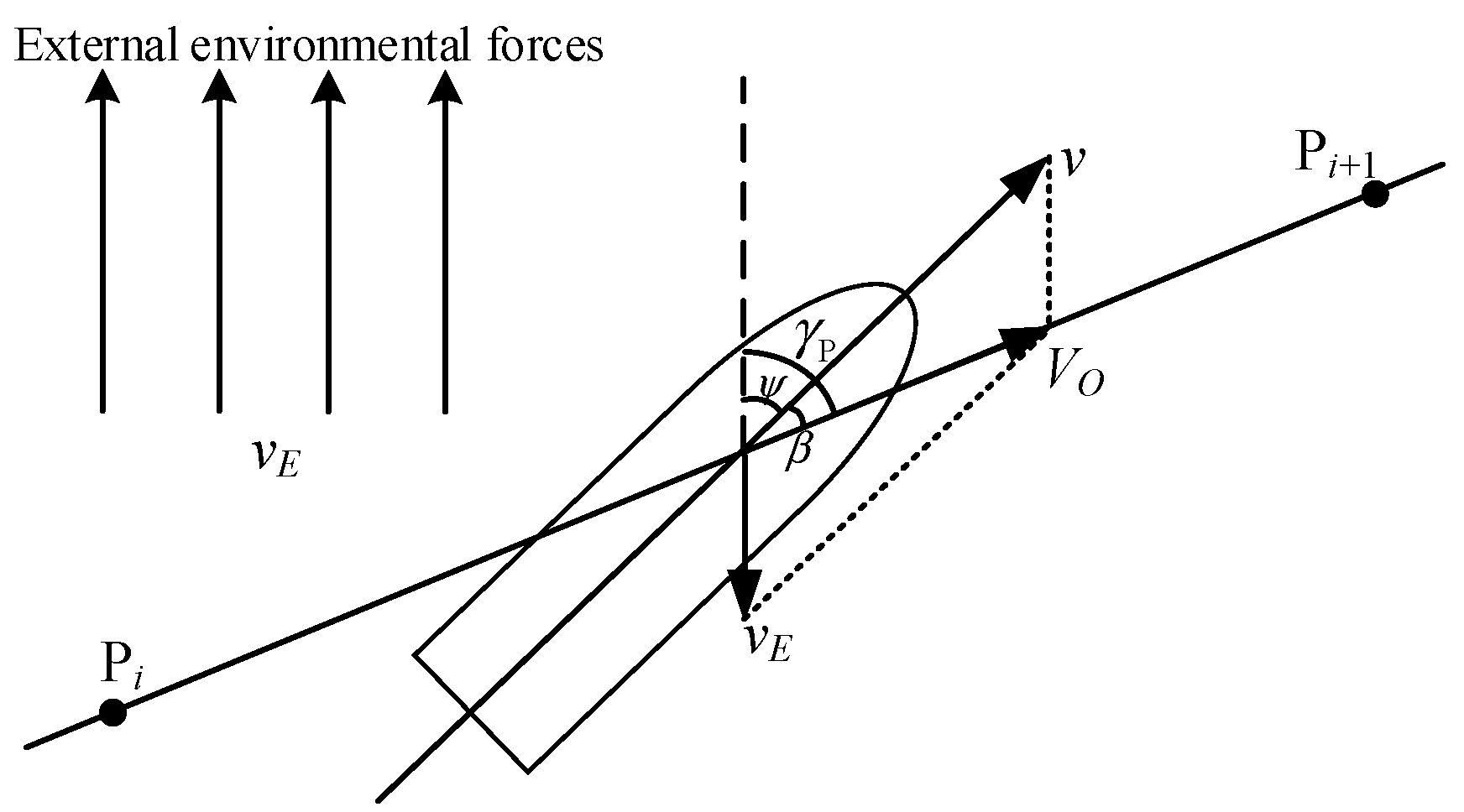
The presence of external disturbances induces a drift angle (β) that separates a vessel’s heading (ψ) from its Course over Ground (COG), as shown in Figure 6. As a result, effective path tracking requires the controller to intentionally offset the heading from the desired track. This strategy creates a lateral velocity component to counteract the disturbance forces. The control objective is thus to find the necessary heading that nullifies the effect of the current, formulated as:
lim t y e t 0
lim t ψ C P i P i 1 β
The time derivative of the lateral tracking error ye(t) is given by:
y ˙ e t = V 0 sin Ψ + β γ p
For restricted environment, the drift angle β is typically small (|β| < 5°), justifying the small-angle approximation (cosβ ≈ 1, sinββ). The derivative of the cross-track error, y ˙ e t , thus simplifies to:
y ˙ e t = V 0 sin Ψ γ p + V 0 cos Ψ γ p β
An integral virtual control term, yint, is introduced to represent the estimate of β provided by an adaptive disturbance observer.
ψ L O S γ p tan 1 y e t Δ + y i n t
y ˙ i n t = k β Δ y e t y e t + Δ y i n t 2 + Δ 2
k β = k i e ρ y e 2 t
When the vessel is far from the route (large ye(t)), the exponential function suppresses the gain towards zero. This effectively pauses the integration, preventing the control saturation and overshoot associated with integral windup. As the vessel converges to the reference track (small ye(t)), the gain smoothly rises, fully engaging the integral term. This allows yint to accurately estimate and cancel out the steady-state error caused by the drift angle. Consequently, this approach achieves robust route-following by dynamically compensating for disturbances, while its inherent structure elegantly circumvents the saturation problems found in controllers with fixed integral gains.

3.3. Navigation Strategy Based on Maritime Practice

While the adaptive guidance described in Section 3.2 is effective for general curved waterways, it is insufficient for the extreme hydrodynamic conditions of complex curved waterways. In these hazardous environments, characterized by the “reversing sharp bend” pattern, a purely reactive, error-driven strategy fails to guarantee safety. Safe passage therefore necessitates a proactive navigational strategy derived from the principles of good seamanship. The primary challenge is to counteract the powerful and asymmetric forces generated by sharp curvatures and bank interactions. Proximity to the concave bank induces a strong yawing moment from bow cushion and stern suction, while the convex bank exposes the vessel to strong cross-currents that push it towards grounding. It is to manage these combined, destabilizing effects that a more sophisticated, practice-based approach is required.
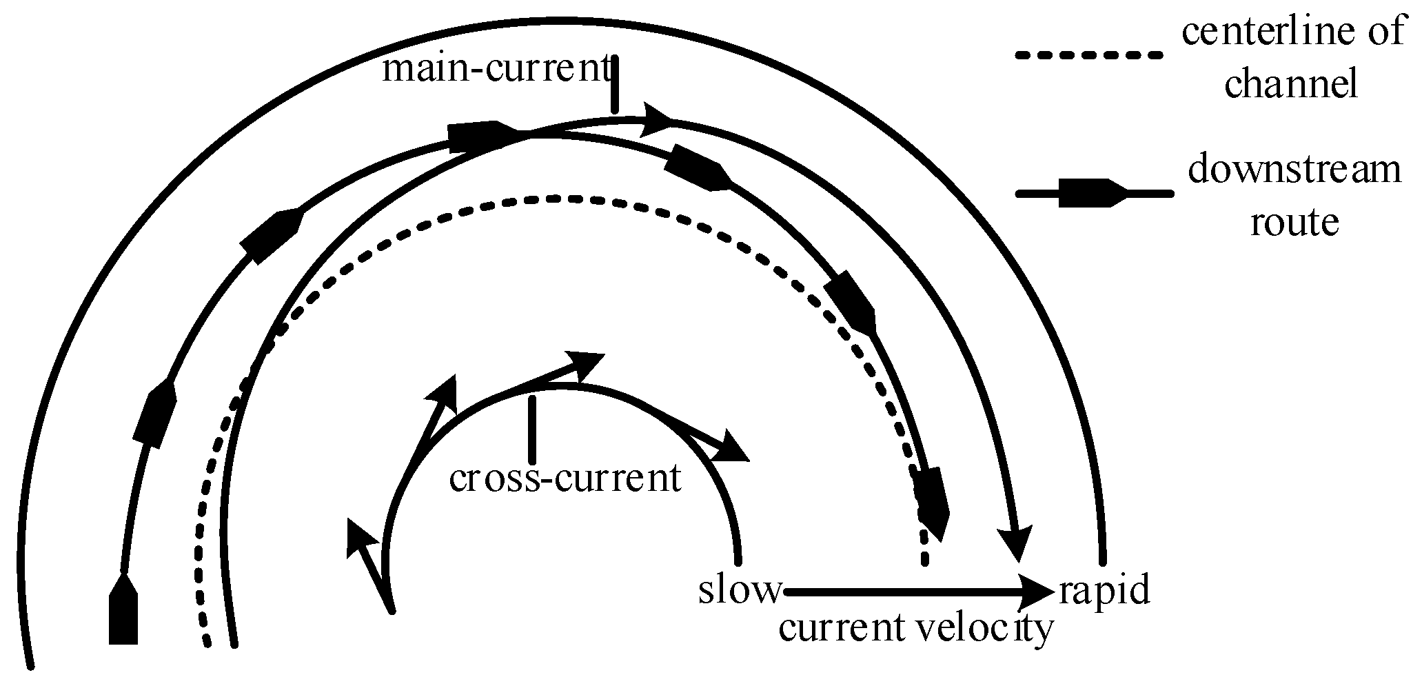
To address these challenges, the guidance framework is enhanced to embed the synergistic navigational strategy known as “holding high and taking low”, as shown in Figure 7. This practice-based approach involves a sophisticated interplay of positioning and attitude control. “Holding High” is a positional strategy that proactively establishes a safety margin by offsetting the planned track towards the up-current side of the main streamline. Complementing this, “taking low” is a heading strategy that mitigates the drift force by adjusting the vessel’s heading to minimize its angle of attack relative to the cross-current. The synergy is critical: an advantageous lateral position from “holding high” allows the vessel to maintain stability with only a minimal corrective heading from “taking low.” This strategy is implemented by generating a strategically safer, non-centerline reference trajectory for the underlying adaptive LOS controller to follow, ensuring a smooth and controlled transit through the bend.
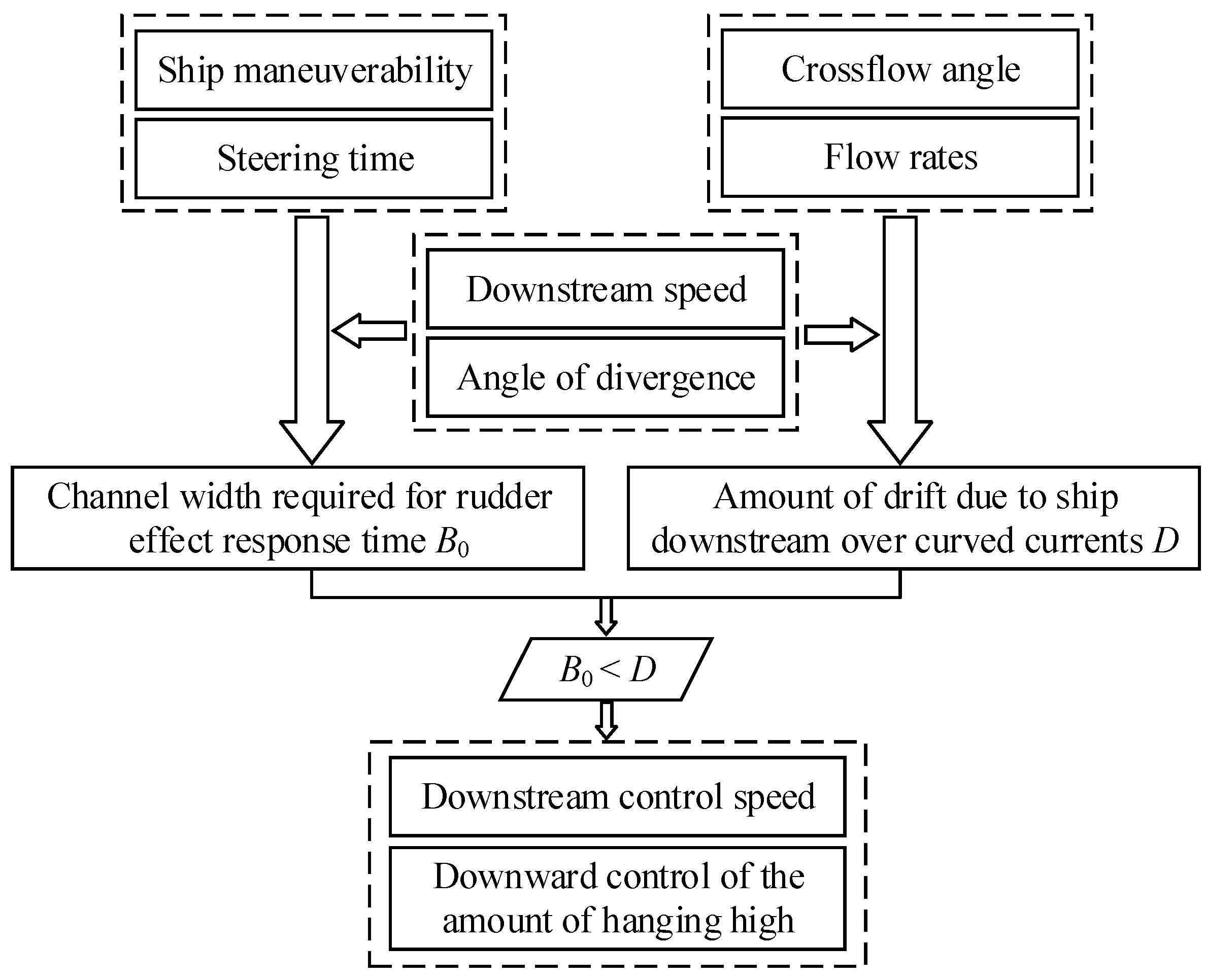
The core principle dictates that the required lateral sea room for rudder response, B0, must be less than or equal to the permissible lateral drift induced by the current, D. This critical relationship is expressed as: B0D.
The required sea room, B0, is derived from the rudder response advance Re and the drift angle β (B0 = Re × sinβ). The advance Re itself depends on vessel speed Vs, its time constant T, and the rudder execution time t0:
R e = V s T + t 0 2
where t0 = 0.4 × δ. The permissible drift, D, over a channel segment S is a function of the vessel’s speed Vs, the current’s velocity u, the cross-current angle φ, and the drift angle β:
D = u sin φ + V s sin β S u cos φ + V s cos β
In accordance with the “Navigation standards of inland waterway” for Class I–V waterways (which specify a 3° drift angle), we define the unit displacement length S as the distance traveled per 3° heading change.
S = θ π R 180 °
Adhering to the B0D constraint provides a quantitative basis for the “holding high and taking low” piloting strategy, ensuring sufficient maneuvering space is maintained throughout the turn, and the solution process is shown in Figure 8.
This study investigates the performance of a specific ship type when navigating a bend downstream. Based on a calculation method for turning speed and lateral deviation, six sets of conditions were simulated. The objective was to determine the relationship between the parameters B0, D, and the vessel’s speed.
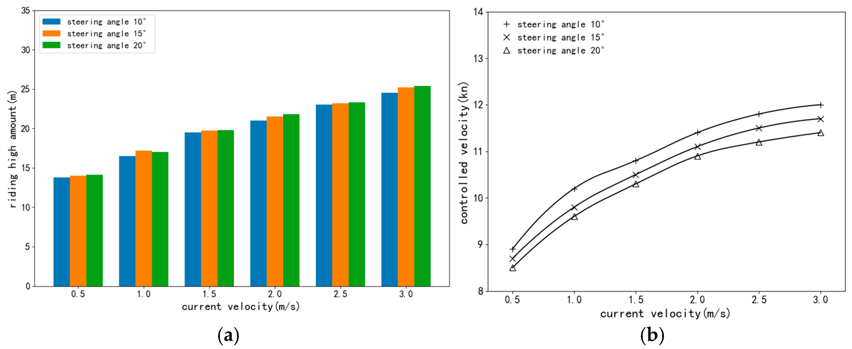
The analysis of the vessel’s turning maneuver, as illustrated in Figure 9, reveals the relationship between vessel speed and two key parameters: the available navigation width (B0) and the required swept path width (D). As vessel speed increases, B0 gradually decreases while D increases linearly. The intersection of these two curves defines the critical turning speed, representing the maximum velocity for safely negotiating the downstream bend. In physical terms, at this critical speed, the required maneuvering space (D) precisely matches the available navigation width (B0), ensuring the vessel’s swept path remains entirely within the confines of the navigation channel, see Figure 10.
The analysis further reveals that the required turning width is predominantly influenced by the current velocity, increasing from 14 m to 25 m as the current velocity rises from 0.5 m/s to 3.0 m/s. This confirms the operational necessity of reserving more channel width in stronger currents. Notably, the required width is largely insensitive to the magnitude of the applied rudder angle. This indicates that for downstream turns, vessel speed and current velocity are the dominant factors governing navigational safety, while the specific rudder command plays a minor role in determining the spatial requirement of the turn.
To proactively counteract the cross-currents in curved waterways, a trajectory optimization strategy inspired by the mariner’s “holding high and taking low” heuristic is proposed. This strategy utilizes the required lateral offset (doffset), calculated based on vessel speed and current velocity, to dynamically adjust the vessel’s tracking behavior, as illustrated in Figure 11. While the vessel follows the centerline in straight segments, a “holding high” maneuver is initiated upon approaching a turn. The vessel’s actual position is virtually shifted towards the concave bank by the distance doffset to establish a “holding high” position, P o . This offset is central to the control strategy’s effectiveness. In a conventional tracking approach, the target point P would be determined based on the vessel’s actual position P o . However, in our proposed strategy, the calculation of the LOS vector is based on the vessel’s position PO prior to adopting the holding-high strategy. Based on the taking-low strategy, the LOS guidance angle α′ required for the target waypoint P′ determined based on PO is significantly greater than the angle α required when turning from the actual position P o , resulting in a smaller curvature radius for the vessel’s turning trajectory and guiding the ship more safely through the turn.
Consequently, the final target heading commanded by the controller has a smaller compensatory component. This allows the vessel to balance the lateral thrust of the current with a reduced angle of attack relative to the cross-current. This method not only effectively neutralizes the current’s force, drastically minimizing the risk of grounding on the concave bank, but also facilitates a smoother and more stable turning maneuver, achieving the “taking low” effect in terms of control effort and route stability.

3.4. Optimal PID Control Method Based on DQ-Learning Algorithm

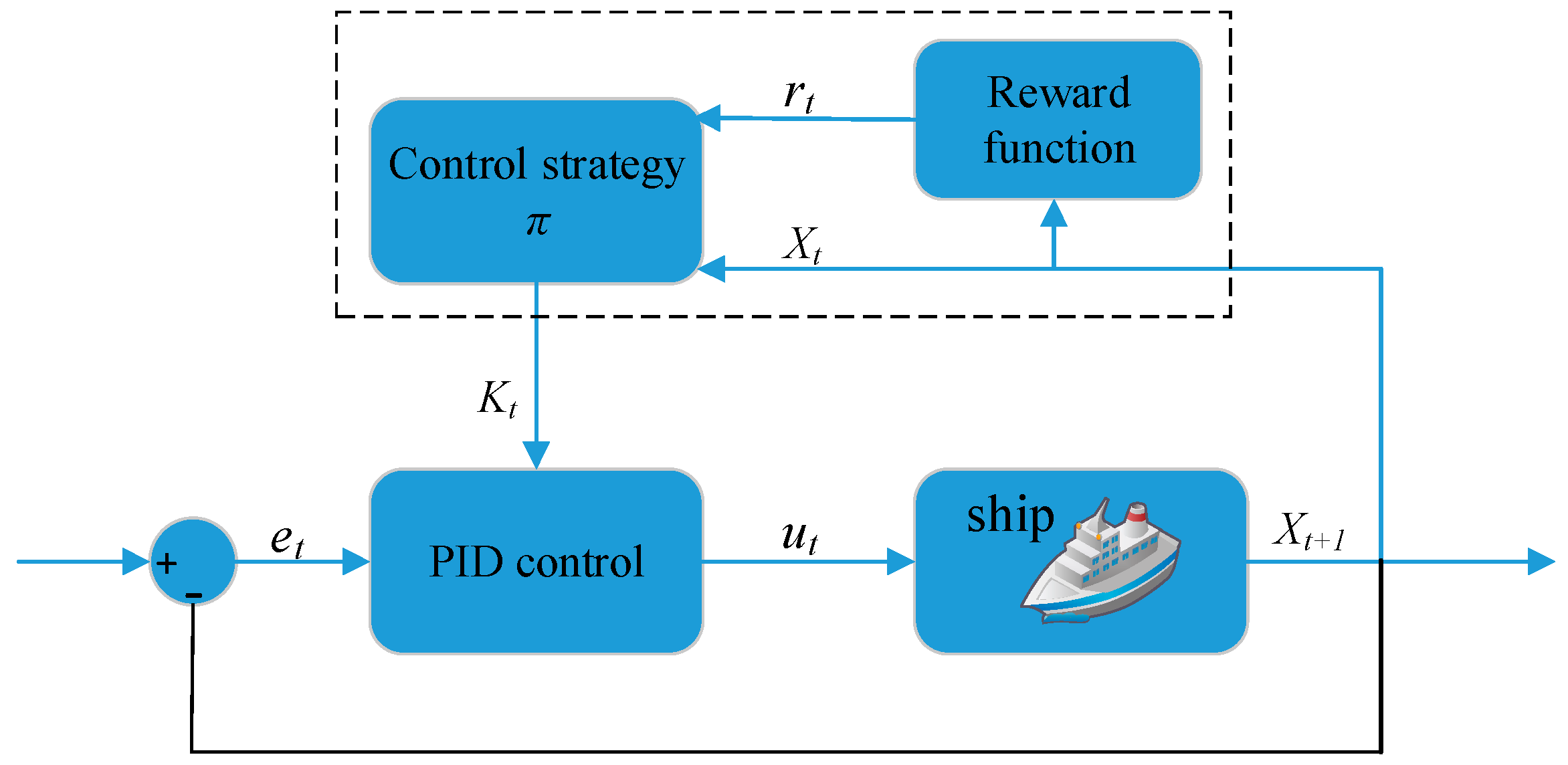
The execution of autonomous navigation commands fundamentally relies on a heading controller, a core component of any marine autopilot, which translates a desired heading into precise rudder actions. Effective heading keeping control is therefore essential to translate the desired trajectory from the guidance layer into an accurate route. While conventional fixed-gain PID controllers are ill-suited for the complex dynamics of ship motion. Their static parameters cannot adapt to the vessel’s significant inertia, time-lag, and nonlinearities, nor to the hydrodynamic coefficients that fluctuate with operating conditions. This results in poor heading keeping, leading to significant heading fluctuations and excessive rudder activity. Consequently, a fixed-gain PID controller is inadequate for maintaining high-performance control across the diverse operational conditions encountered, especially in challenging environments like curved waterways, see Figure 12.
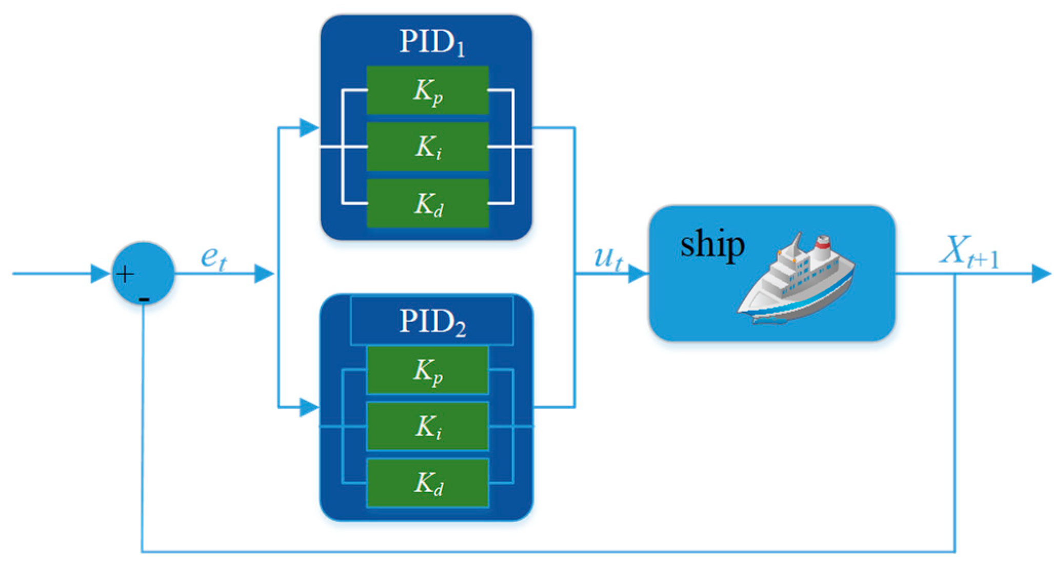
To overcome the limitations of fixed-gain PID, an adaptive PID controller is proposed where the parameters, kt, are tuned in real-time using a Reinforcement Learning (RL) agent. The parameter tuning problem is formulated as a Markov Decision Process (MDP), where the agent’s goal is to learn an optimal policy, π*, that maps system states, xt, to optimal PID parameters, kt. This policy aims to maximize the expected cumulative reward, J*:
J * = m a x J π = m a x E π R t | x t = x
This is achieved by learning the optimal action-value function, Q*(xt, kt), which represents the maximum expected reward for selecting parameters kt in state xt. The Q* function adheres to the Bellman optimality equation:
Q * x t , k t = E r t + 1 + γ   max k Q * r t + 1 , k t + 1 | x t , k t
The term rt+1 represents the immediate reward for the transition, while γ is the discount factor for future rewards. During training, an ε-greedy policy is used for exploration to iteratively approximate the optimal Q-function. The final optimal policy, π*, selects the action that maximizes this function:
π * = a r g   max k Q * x t , k
However, standard Q-learning suffers from maximization bias. To address this, an adaptive PID controller is implemented using the double Q-learning algorithm, which employs two independent estimators, QA and QB. The key innovation of this method is the decoupling of action selection from value estimation. For instance, when an action is selected based on QA, the update target is derived from the value estimated by QB. This cross-update mechanism mitigates the overestimation bias. The update rule for QA is therefore as follows:
Q A x t , k t Q A x t , k t + α r t + 1 + γ   max k   Q B x t + 1 , k t + 1 Q A x t , k t
The update rule for QB is symmetrical:
Q B x t , k t Q B x t , k t + α r t + 1 + γ   max k   Q A x t + 1 , k t + 1 Q B x t , k t
The double Q-learning algorithm mitigates estimation bias by decoupling action selection from value estimation. Using one Q-function’s value to update the other decorrelates the estimates. The algorithm’s structure is depicted in Figure 13.
Discretizing state-action spaces for Q-learning presents a dilemma: coarse grids yield poor performance [42], while fine grids are computationally prohibitive due to the “curse of dimensionality”. To circumvent this, an incremental discretization approach for both state and action spaces is introduced. The state space X is built adaptively. A new state xt+1 is incorporated only if its novelty, measured by a membership function η, surpasses a threshold ρ relative to all existing states in X. This is determined by the condition:
η x , x > ρ
where x’ is the new state xt+1. A multi-level discretization is used, defined by Z levels with corresponding thresholds Λ = (ρ0, ρ1, …, ρz). In each time step, the Q-learning agent selects an action kK based on its policy π to tune the PID controller.
An incremental action space discretization is triggered if the state-action pair (xt, kt) remains static for N consecutive steps. To improve learning efficiency, Stochastic Experience Replay (SER) [43,44] is employed. This involves maintaining a replay buffer R of size m, which stores recent state transitions. Instead of learning from sequential experiences, our Q-function is updated by sampling from this buffer. This approach leverages the data efficiency of model-based methods—by replaying experiences—while retaining the simplicity and robustness of a model-free architecture. The buffer itself is a standard circular queue operating under a FIFO replacement policy.
The main steps of the PID control method for double Q-learning are as follows (Algorithm 1):
Algorithm 1 PID control method for double Q-learning
Input: α, γ, r(-, -), ω0, K, η(-, -), n, m, N, Λ, ∆
x0: The state of the ship at the moment t0 is obtained by the ship’s sensors
Initialize QA, QB, use same structure but different weights
(1)
   While True:
(2)
         Take the ϵ-greedy strategy action selection → kt
(3)
         Setting the current temporal memory Mt = (xt, kt)
(4)
         The system executes the action and observes the post-execution state xt+1 and the earned reward rt+1
(5)
         If the system state changes:
(6)
                    Save the experience τ= (xt, kt, xt+1, rt+1) after the execution of the action in the buffer R
(7)
               Find the state xi X that is closest to xt+1
(8)
               If xt+1 lies near xi, then:
(9)
                  Double Q-learning update→Update QA and QB according to Equations (36) and (37)
(10)
             else:
(11)
                  Include xt+1 in the state space X
(12)
                  Update QA and QB based on the new state xt+1
(13)
            end if
(14)
         else
(15)
              Implementation of active incremental learning mechanisms
(16)
        end if
(17)
        Implementation of a randomized experience playback mechanism
(18)
        Update system status for next cycle
(19)
   end
To promote exploration and minimize manual setup, the initial controller gains kt = (kp, ki, kd) are randomly drawn from a uniform distribution, with each gain selected from within a specified minimum and maximum bound.
Effective reward shaping is crucial for route-tracking control in complex waterways. Conventional reward functions based on linear error penalties are inadequate as they disregard the vessel’s dynamics and the need for smooth maneuvering. Therefore, this work utilizes a Gaussian function to structure the reward signal, providing a more effective learning gradient for the control agent. The reward function is defined as:
r t x t , x r e q = 1 2 π σ e x t x r e q 2 2 σ 2
In this formulation, ||xtxreq|| represents the composite tracking error between the vessel’s state xt and the reference state xreq, while the constant σ tunes the reward’s sensitivity to this error. The key advantage of this Gaussian-based reward is that it creates a smooth, nonlinear reward peak around the target. This structure encourages the controller to minimize tracking deviations while maintaining control stability, a paramount requirement for navigating confined channels. To balance exploration and exploitation, an ϵ-greedy policy is implemented where the exploration rate ϵt is annealed over time. An initial high rate of exploration prevents premature convergence to local optima, while a subsequent shift towards exploitation allows for the refinement of the control strategy. The exploration rate follows an exponential decay function:
ϵ t = ϵ 0 + ϵ 1 e t
With the base and decay parameters set to ϵ0 = 0.05 and ϵ1 = 0.03, respectively. This schedule ensures that the agent’s action selection gradually transitions from being primarily random (exploration) to being primarily determined by the learned policy (exploitation). This structured approach is critical for efficiently discovering a globally optimal control policy.
The algorithm’s performance was validated in a heading control task where the reference setpoint was dynamically switched between 30° and 50°. We used standard hyperparameters (α = 0.2, γ = 0.95, σ = 0.1), and the PID gain vector k t n = { k p n , k i n , k d n } was initialized randomly to promote exploration.
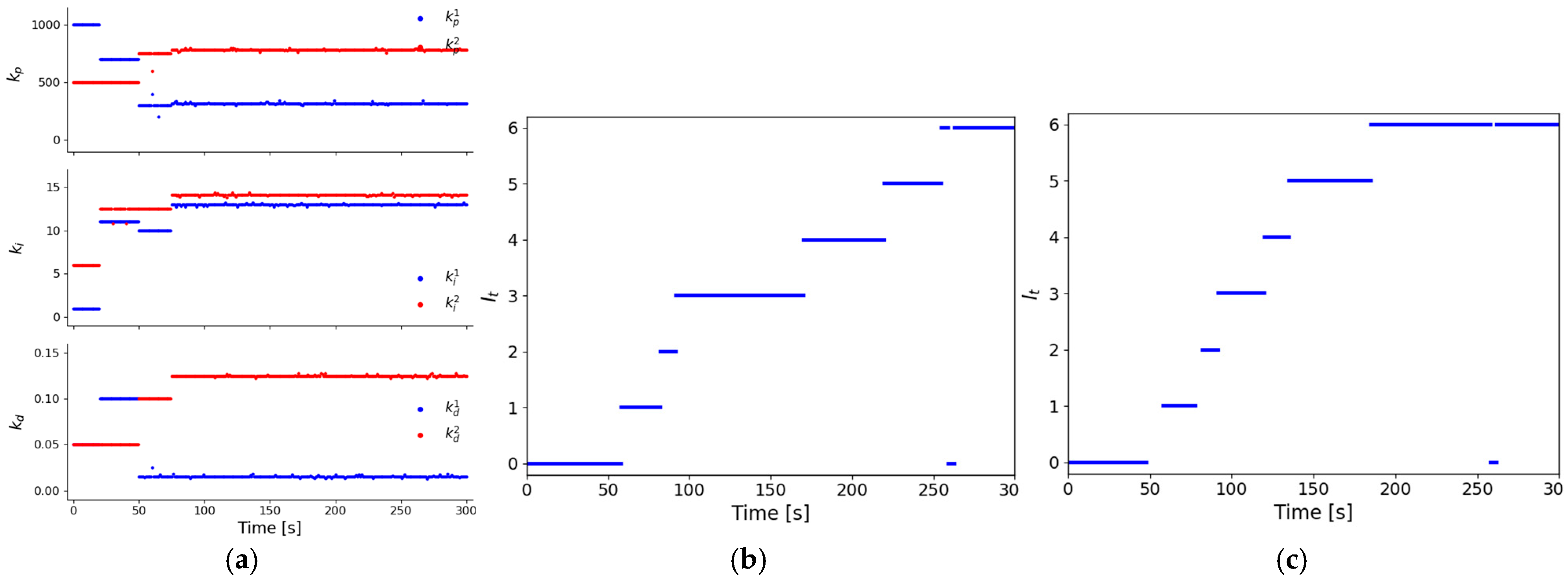
The experimental results demonstrate the algorithm’s rapid and efficient online learning capability for optimal controller parameters. As shown in Figure 14a, during a 300 s simulation, the PID gains converged to a stable, high-performance region within approximately 100 s, showcasing the agent’s real-time adaptive capability. Concurrently, the action space discretization level successfully evolved to its pre-set maximum of lmax = 8 (Figure 14b,c), confirming the efficacy of the incremental learning mechanism. These findings verify that the method can adapt to new commands online and reliably identify an optimal gain set within a single maneuver.
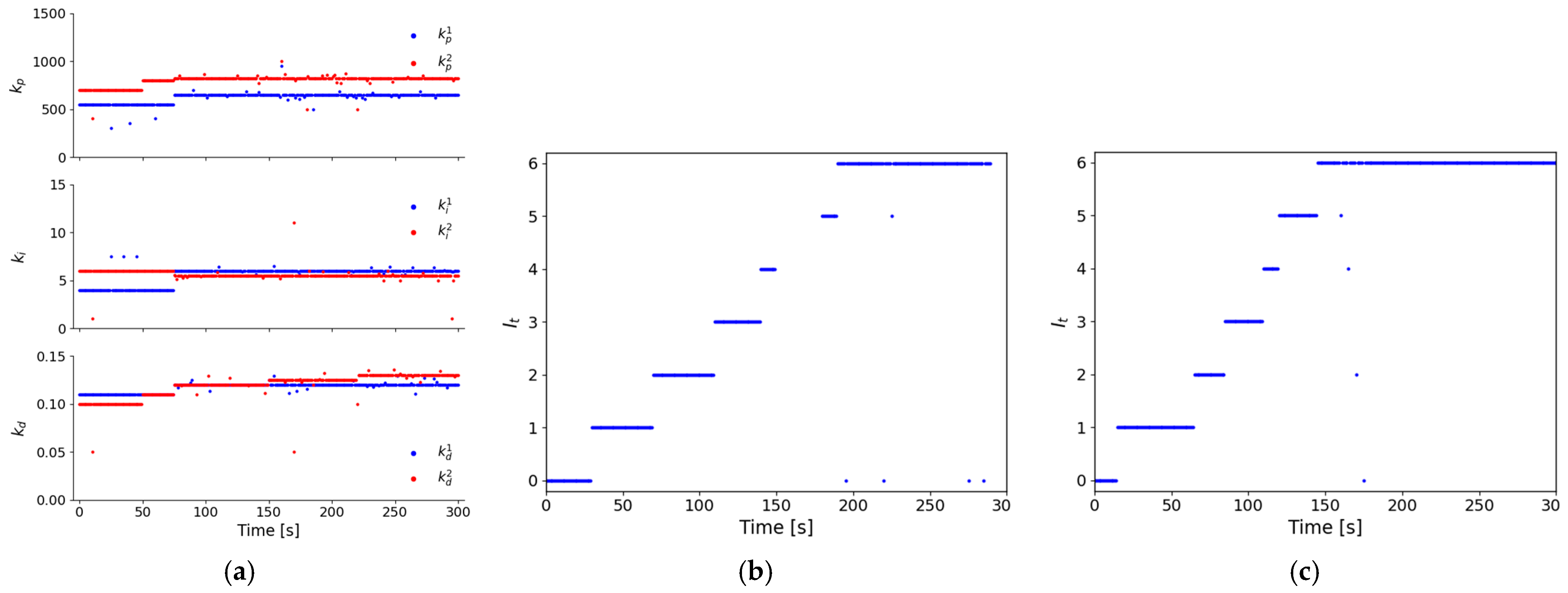
To evaluate the algorithm’s robustness, a second experiment was conducted under significant environmental disturbances (a 5 m/s wind and a 0.5 m/s current). Despite the substantially altered plant dynamics, the agent’s online learning efficiency remained remarkably stable. As shown in Figure 15, the system again converged to an optimal PID gain set within 300 s, a performance on par with the disturbance-free case. This result confirms that the proposed method is highly robust, capable of adapting to substantial variations in the plant dynamics without compromising its online convergence speed or solution quality.
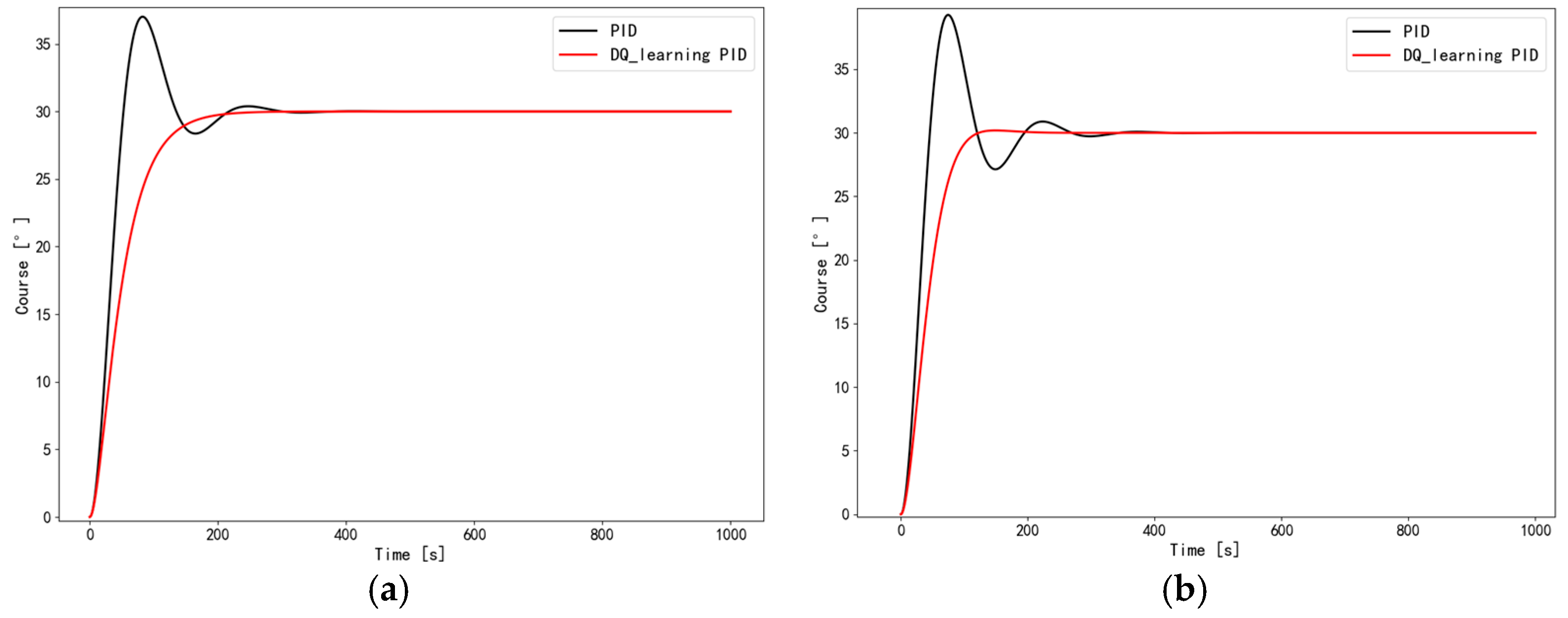
To verify the effectiveness and superiority of the proposed control algorithm, a comparative analysis was conducted against a conventional, fixed-gain PID controller. The heading control task (from 0° to 30°) was simulated in a still-water environment under two distinct speed conditions: 8 m/s and 4 m/s. The conventional PID gains were manually set to kp = 500, ki = 10, and kd = 0.01, see Figure 16.
The results demonstrate the clear superiority of the double Q-learning PID (DQ-PID) approach. At 8 m/s, the DQ-PID achieved convergence in 157 s with a minimal 1% overshoot. In contrast, the conventional PID required 277 s and produced a significant 14.3% overshoot. At 4 m/s, the performance gap remained. The DQ-PID converged in 215 s with 2.7% overshoot, whereas the conventional PID took 410 s and had an 8.3% overshoot. Overall, the double-Q-learning-based PID controller consistently delivered faster response times, higher precision (lower deviation), and significantly improved stability across different operating conditions compared to the conventional method.
From a practical implementation perspective, the computational aspects of this RL-based approach are highly feasible. The intensive training phase, where the agent learns its policy over many iterations, is typically performed offline in a simulation environment and does not impact real-time operation. During onboard deployment, the controller is only required to perform the inference task—a single forward pass of the trained neural network to determine the optimal PID gain adjustments for the current state. This inference operation is computationally lightweight, typically executing in milliseconds, and is thus well within the cycle time of a standard marine autopilot. The convergence speed observed in our online learning experiments, where the agent adapts within 100–300 s, further underscores the algorithm’s efficiency for real-time adaptive tuning.

4. Experimental Validation and Performance Analysis of Motion Control

To validate the proposed motion control framework, this chapter details a series of simulation experiments conducted under progressively challenging conditions. These experiments correspond to the three types of curved waterways defined in Section 2.1, systematically evaluating the framework’s baseline performance, robustness, and the effectiveness of its embedded navigational strategy. The “Yaozui” section of the Yangtze River serves as the realistic testbed, and all simulations were implemented in Python 3.8.

4.1. Performance in Hydrostatic Conditions

This section establishes the baseline performance in an ideal, disturbance-free environment, representative of a “flat bend” found in well-dredged maritime channels. The objective is to evaluate the fundamental safety and accuracy advantages of the proposed full framework over a conventional approach.
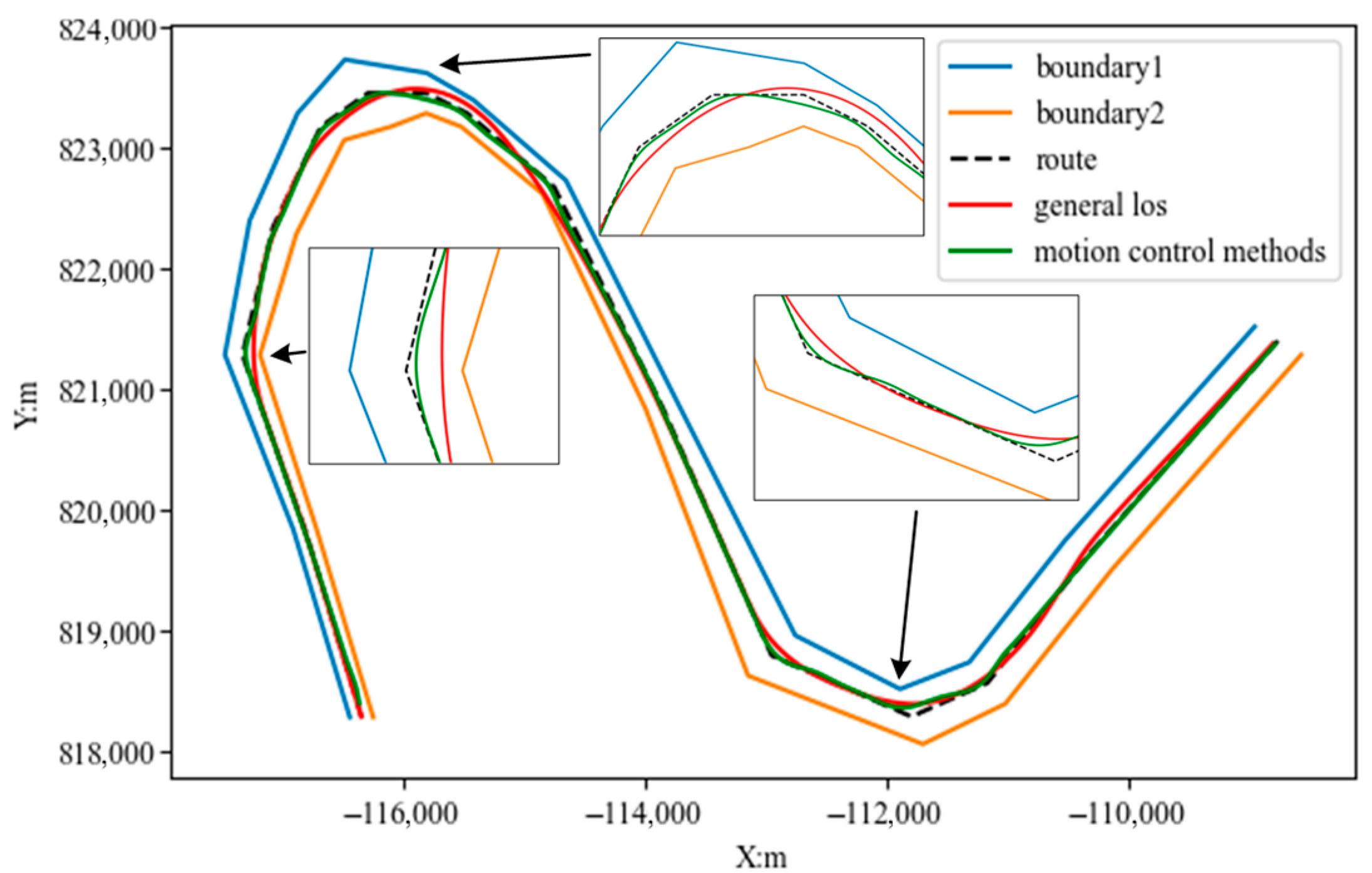
A visual comparison of the route-tracking performance for both control schemes is provided in Figure 17. While both the benchmark method (general los) and the proposed method (motion control methods) successfully navigate the entire segment, a distinct difference in fidelity is evident. The trajectory of the proposed method closely adheres to the reference route, whereas the benchmark method exhibits a noticeable “corner-cutting” behavior at the curve apexes. This visually demonstrates that the proposed method achieves superior tracking precision, even under ideal conditions.
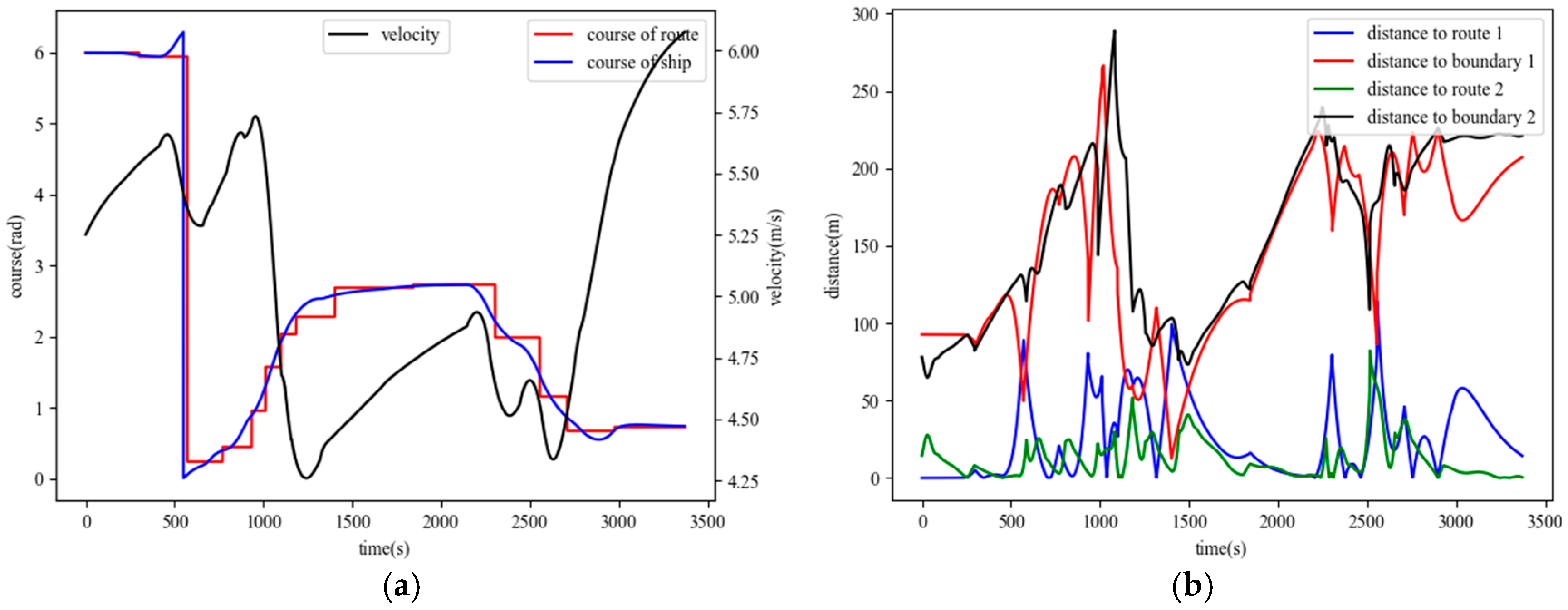
The dynamic response and a quantitative performance analysis are presented in Figure 18. Figure 18a details the heading and velocity response of the proposed method, showing that the vessel’s actual course effectively tracks the desired course at each waypoint transition without significant overshoot or oscillation, confirming its excellent dynamic stability.
A direct quantitative comparison of tracking accuracy and navigational safety is provided in Figure 18b. The cross-track error (CTE) of the proposed method (green line) is consistently maintained at a much lower level than that of the Benchmark Method (blue line). Notably, during waypoint transitions, the error peaks of the benchmark approach nearly 130 m, whereas the proposed method’s peaks are kept below 90 m with a faster convergence rate. This quantitatively demonstrates the superior accuracy of the proposed method. This higher precision directly translates to improved safety, as the minimum distance to the channel boundary for the proposed method (black line) remains significantly larger than that of the benchmark method (red line), affording a greater safety margin throughout the simulation.
A rigorous quantitative evaluation, summarized in Table 1, substantiates these visual findings. The proposed method significantly outperforms the benchmark across all metrics, achieving a 47.3% reduction in CTE RMSE and a 65.0% reduction in Mean Absolute Heading Error. These numerical results provide decisive evidence of the framework’s superior baseline accuracy and stability.

4.2. Performance Under Environmental Disturbances

This section validates the robustness of the core control algorithms in a more challenging “sharp bend” scenario, representative of a harbor approach or estuary with significant environmental forces. To isolate the performance of the algorithms, the “holding high” strategy was disabled, and both methods tracked the geometric centerline under the influence of a 2 m/s cross-current and a 5 m/s wind.
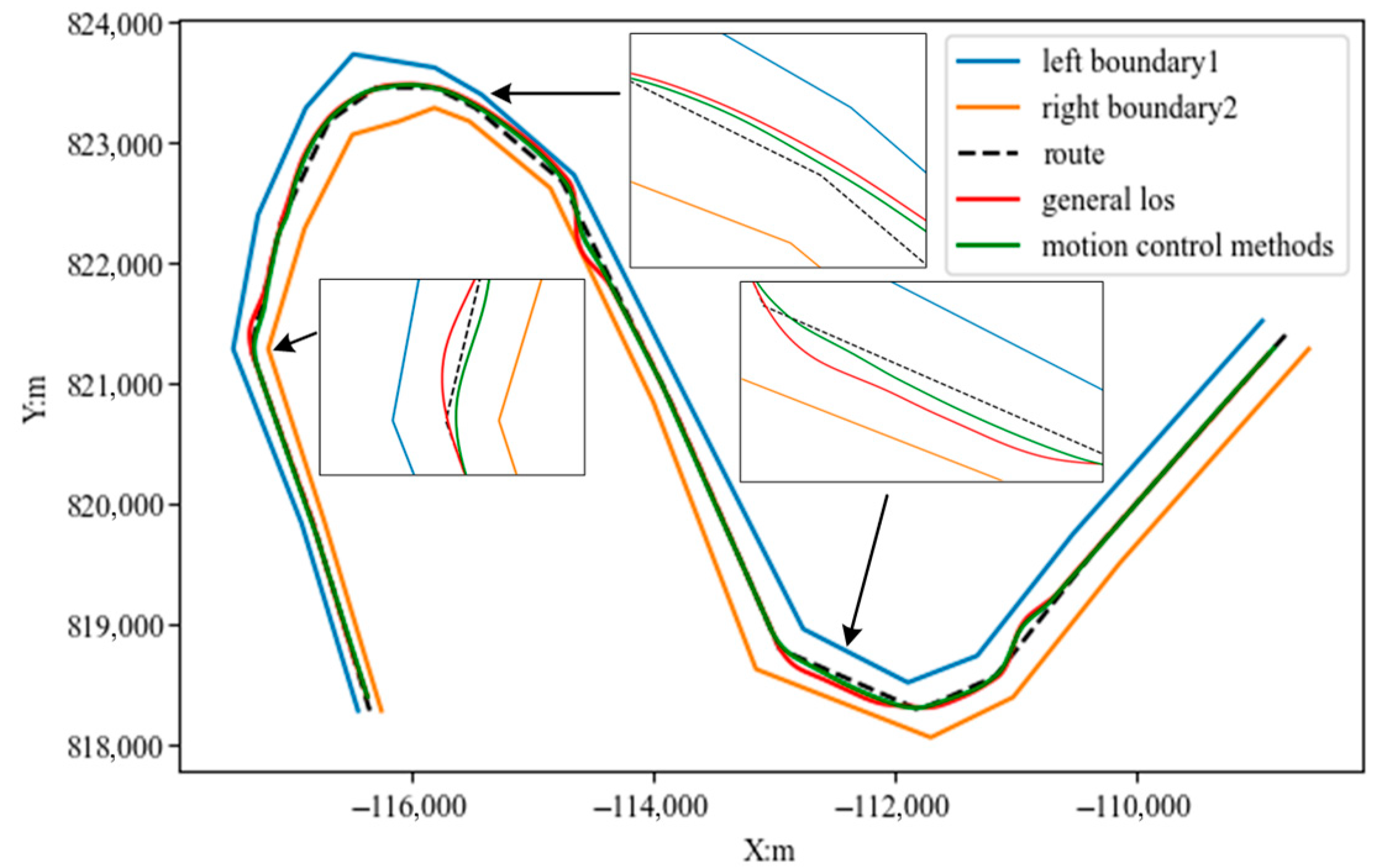
The results, detailed in Figure 19 and Figure 20, highlight the superiority of the proposed framework. Figure 19 visually contrasts the route-tracking performance, where the benchmark method’s trajectory exhibits a large, persistent steady-state error due to its inability to counteract the constant lateral forces. Conversely, the proposed method maintains high fidelity to the reference route, showcasing its effective disturbance rejection.
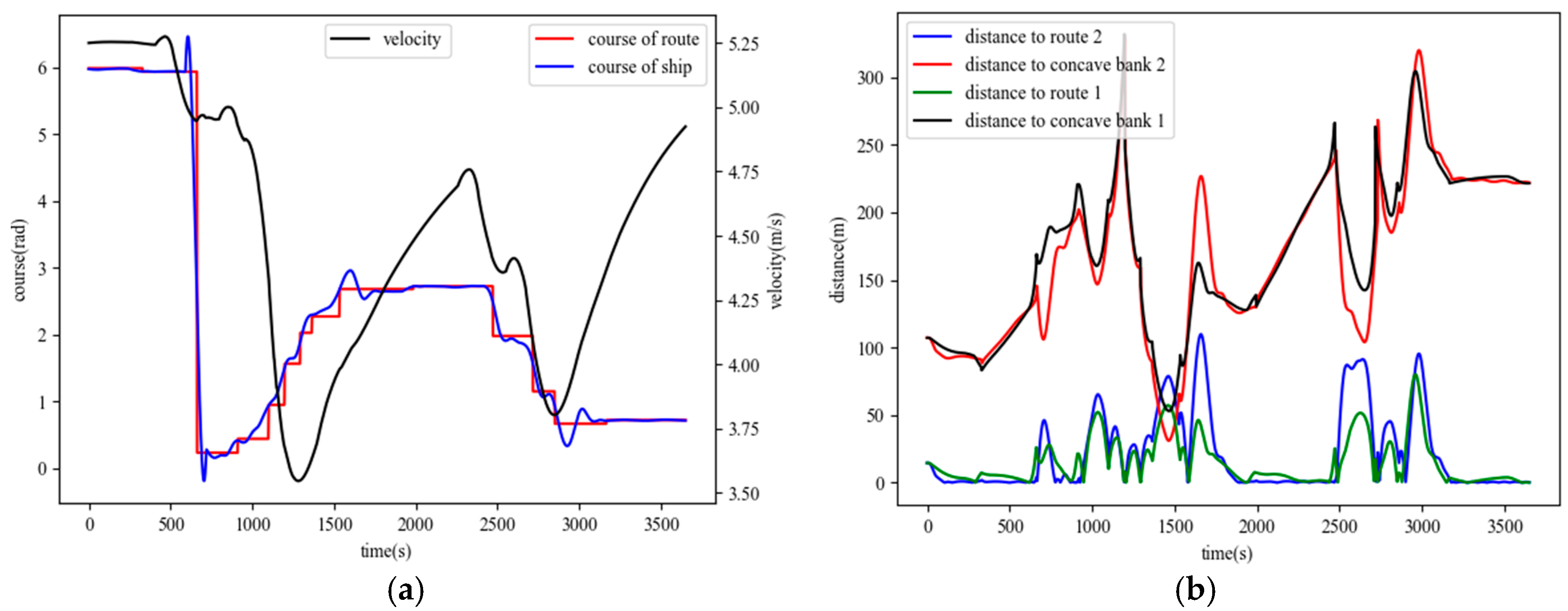
This qualitative observation is substantiated by the quantitative data in Figure 20. The CTE of the benchmark method becomes large and unstable, whereas the proposed method’s CTE is consistently suppressed, confirming that its adaptive mechanisms are effective. This improved accuracy directly translates to enhanced safety, as the proposed method maintains a significantly larger distance to the channel boundaries compared to the risk-prone trajectory of the benchmark. This robust performance is achieved through the synergy of the adaptive LOS guidance, which compensates for external forces, and the RL-tuned PID, which adapts to the resultant dynamics.
The quantitative results, presented in Table 2, powerfully validate the robustness and adaptability of the proposed control framework. Even in the presence of significant wind and current disturbances, the proposed method maintained a high level of performance, achieving a 41.3% lower CTE RMSE and a 46.8% smaller Mean Absolute Heading Error compared to the benchmark. These findings provide decisive evidence that the “dual adaptive” mechanism is highly effective at maintaining control accuracy and stability under adverse conditions. In conclusion, the rigorous simulations demonstrate that the proposed method is not only precise under baseline conditions but, more importantly, is an effective and reliable solution for motion control in challenging, real-world maritime environments.

4.3. Performance Based on Both Environmental Disturbances and Maritime Practice

This final section validates the effectiveness of the “holding high and taking low” strategy in the most hazardous environment: a “reversing sharp bend”, representative of complex inland river navigation. To create a uniquely realistic testbed that reflects the principles of good seamanship, an innovative environmental model was established. It is a known maritime practice that the “holding high” maneuver positions the vessel in the main streamline where the current is strongest. To simulate this, the vessel employing the full strategy was subjected to both a 2 m/s cross-current and an additional 2 m/s mainstream, faithfully replicating the higher-energy environment it is designed to master. The baseline approach, tracking the centerline, was subjected only to the 2 m/s cross-current. Both approaches utilized the same underlying adaptive ILOS + RL-PID algorithms.
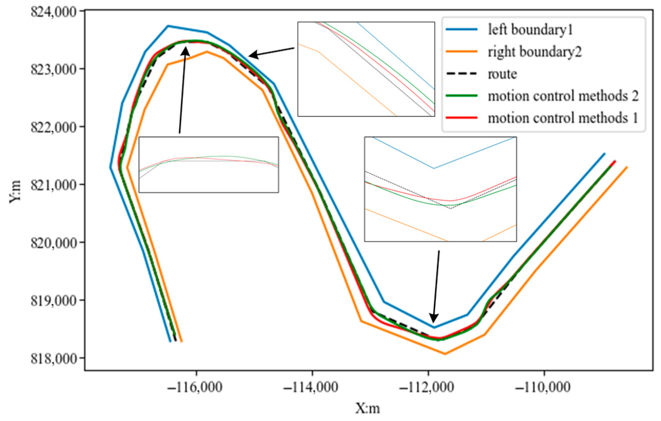
The simulation results powerfully validate the strategy based on practical experience. Figure 21 visually compares the trajectories, showing that the path generated by the full strategy (motion control method 1) is positioned closer to the concave bank before the bends, as intended by the “holding high” principle, compared to the path from centerline tracking (motion control method 2), see Figure 22.
The crucial quantitative evidence is presented in Figure 23, which directly compares the minimum distance to the hazardous concave (outer) bank for both approaches. The results are decisive: the centerline tracking approach reached a minimum distance of only 53.0 m from the bank. In contrast, the vessel employing the “holding high and taking low” strategy maintained a minimum distance of 79.2 m. This represents a 49.4% increase in the critical safety margin. This quantitative result confirms the core hypothesis: the control authority gained from “holding high” in the stronger current, combined with the attitude optimization of “taking low” allows the vessel to execute a more controlled turn and stay significantly further from danger. Furthermore, the low cross-track errors for both methods relative to their respective paths indicate that this substantial safety enhancement is a direct result of the superior navigational strategy, which effectively harnesses the current’s energy instead of merely fighting it.
The simulation, featuring an innovative environmental model that reflects the higher current velocity in the channel’s outer bend, unequivocally demonstrates the practical value of the “holding high and taking low” strategy. By proactively positioning the vessel in the main current, the proposed guidance method gains the necessary control authority to safely and efficiently navigate sharp bends, even under severe environmental forces. This confirms that embedding good seamanship into the control framework is a critical component for achieving robust safety in real-world, complex waterways.

4.4. Discussion and Limitations

The simulation results systematically validate our core hypothesis: that a control framework synergizing proactive, seamanship-informed guidance with reactive, adaptive control significantly outperforms conventional methods in challenging waterways. The experiments clearly distinguished the roles of our framework’s two layers. The adaptive control layer provided a robust foundation for high-fidelity heading keeping under general disturbances, a task where the fixed-gain benchmark failed. Yet, the most critical finding came from the third experiment: even this powerful adaptive controller struggled to ensure safety on a naive centerline path in extreme conditions. This unequivocally demonstrates that a strategically superior path, generated by encoding the “holding high and taking low” practice, is not merely an optimization but a fundamental requirement for safe navigation. Our guidance rules’ ability to harness the current’s energy, rather than merely fighting it, is the key innovation that provides a level of safety unattainable through purely reactive control.
However, the scope of this study has its limits, which define the necessary next steps for future research. A primary limitation is that the validation is purely simulation-based. Real-world complexities such as sensor noise, actuator dynamics, and unpredictable wave disturbances were not modeled. The hydrodynamic environment was also an idealization, simplifying the non-uniform flow fields of real river bends into a uniform cross-current. Furthermore, while our environmental model is grounded in ENC data, a potential discrepancy can exist between this static cartographic information and real-time channel conditions. The experiments were also conducted in a single-vessel environment, excluding the influence of traffic and formal navigational rules, such as two-way traffic separation schemes. Finally, this study did not include a direct comparison with real-world AIS trajectories. This is partly due to the difficulty in obtaining a complete dataset that includes corresponding environmental conditions. More fundamentally, however, it highlights a conceptual challenge: in the current phase of human-piloted navigation, real-world trajectories are often inconsistent, dictated by subjective judgment, and may not always represent an optimal or even safe maneuver. The objective of this forward-looking framework is therefore not to replicate the variability of current human practice, but to establish a new, consistently safe benchmark based on the principles of good seamanship. Future work will involve validating the framework against high-fidelity, curated real-world data, with this normative goal in mind.

5. Conclusions

A novel hierarchical adaptive control framework for confined and curved waterways is introduced and validated. A key contribution of this work is its success in bridging the gap between modern control theory and the nuanced principles of good seamanship. By encoding a practice-based navigational strategy into an adaptive guidance layer and coupling it with an RL-tuned adaptive control layer, the framework demonstrated exceptional performance and a significant enhancement in navigational safety.
Quantitatively, the framework’s superiority was decisively confirmed. In the most hazardous scenario with a 3 m/s cross-current, the proposed method increased the minimum safety margin from the bank by more than 49% compared to a conventional approach, while simultaneously reducing peak tracking errors. This was achieved through the synergistic interplay of the two layers: the guidance layer planned a demonstrably safer path, while the control layer ensured its high-fidelity execution with stable heading and speed management.
Future work will focus on addressing the limitations outlined in Section 4.4, with immediate priorities on extending the framework to multi-vessel scenarios and bridging the sim-to-real gap through Hardware-in-the-Loop simulations. Ultimately, this research paves the way for more intelligent autonomous navigation systems capable of operating safely and reliably in the world’s most challenging maritime environments.

Author Contributions

Conceptualization, L.H. and J.C.; Methodology, L.H. and J.C.; Software, J.C.; Validation, J.C.; Formal analysis, J.C.; Investigation, J.C.; Resources, J.C.; Data curation, J.C.; Writing – original draft, J.C.; Writing – review & editing, L.H. and J.C.; Visualization, J.C.; Supervision, L.H.; Project administration, L.H.; Funding acquisition, L.H. All authors have read and agreed to the published version of the manuscript.

Funding

This research was funded the National Key Research and Development Program. Grant number 2019YFB1600603. And The APC was funded by 2019YFB1600603.

Data Availability Statement

The data presented in this study are available on request from the corresponding author due to the data presented in this study are all processed simulation data.

Conflicts of Interest

The authors declare no conflict of interest.

Abbreviations

The following abbreviations are used in this manuscript:
RLReinforce Learning
ENCsElectronic Navigational Charts
LOSLine-of-Sight
SMCSliding Mode Control
PIDProportional-Integral-Derivative
ESOExtended State Observer
SERStochastic Experience Replay
DQ-PIDDouble Q-learning PID
COGCourse over Ground
CTECross-Track Error
CFDComputational Fluid Dynamics
RMSERoot Mean Square Error
MAEMean Absolute Error

References

  1. Wu, B.; Xu, X.; Teixeira, Â.P.; Yan, X.; Jiang, J. An Inland Waterway Traffic Complexity Evaluation Method Using Radar Sequential Images. Ocean Eng. 2025, 315, 119842. [Google Scholar] [CrossRef]
  2. Yang, B.; Kaidi, S.; Lefrançois, E. Numerical Investigation of the Parameters That May Seriously Impact the Ship Control Lability in Restricted Bending Channels. Ocean Eng. 2022, 266, 112735. [Google Scholar] [CrossRef]
  3. Moreira, L.; Fossen, T.I.; Guedes Soares, C. Path Following Control System for a Tanker Ship Model. Ocean Eng. 2007, 34, 2074–2085. [Google Scholar] [CrossRef]
  4. Xu, H.; Guedes Soares, C. Review of Path-Following Control Systems for Maritime Autonomous Surface Ships. J. Mar. Sci. Appl. 2023, 22, 153–171. [Google Scholar] [CrossRef]
  5. Wang, S.; Ma, F.; Yan, X.; Wu, P.; Liu, Y. Adaptive and Extendable Control of Unmanned Surface Vehicle Formations Using Distributed Deep Reinforcement Learning. Appl. Ocean Res. 2021, 110, 102590. [Google Scholar] [CrossRef]
  6. Ma, H.-J.; Yang, G.-H. Adaptive Fault Tolerant Control of Cooperative Heterogeneous Systems With Actuator Faults and Unreliable Interconnections. IEEE Trans. Autom. Control 2016, 61, 3240–3255. [Google Scholar] [CrossRef]
  7. You, C.; Zhang, R. Hybrid Offline-Online Design for UAV-Enabled Data Harvesting in Probabilistic LoS Channels. IEEE Trans. Wirel. Commun. 2020, 19, 3753–3768. [Google Scholar] [CrossRef]
  8. Faramin, M.; Goudarzi, R.H.; Maleki, A. Track-Keeping Observer-Based Robust Adaptive Control of an Unmanned Surface Vessel by Applying a 4-DOF Maneuvering Model. Ocean Eng. 2019, 183, 11–23. [Google Scholar] [CrossRef]
  9. Li, M.; Guo, C.; Yu, H.; Yuan, Y. Line-of-Sight-Based Global Finite-Time Stable Path Following Control of Unmanned Surface Vehicles with Actuator Saturation. ISA Trans. 2022, 125, 306–317. [Google Scholar] [CrossRef]
  10. Kelasidi, E.; Liljebäck, P.; Pettersen, K.Y.; Gravdahl, J.T. Integral Line-of-Sight Guidance for Path Following Control of Underwater Snake Robots: Theory and Experiments. IEEE Trans. Robot. 2017, 33, 610–628. [Google Scholar] [CrossRef]
  11. Caharija, W.; Pettersen, K.Y.; Bibuli, M.; Calado, P.; Zereik, E.; Braga, J.; Gravdahl, J.T.; Sørensen, A.J.; Milovanović, M.; Bruzzone, G. Integral Line-of-Sight Guidance and Control of Underactuated Marine Vehicles: Theory, Simulations, and Experiments. IEEE Trans. Control Syst. Technol. 2016, 24, 1623–1642. [Google Scholar] [CrossRef]
  12. Wan, L.; Su, Y.; Zhang, H.; Shi, B.; AbouOmar, M.S. An Improved Integral Light-of-Sight Guidance Law for Path Following of Unmanned Surface Vehicles. Ocean Eng. 2020, 205, 107302. [Google Scholar] [CrossRef]
  13. Borhaug, E.; Pavlov, A.; Pettersen, K.Y. Integral LOS Control for Path Following of Underactuated Marine Surface Vessels in the Presence of Constant Ocean Currents. In Proceedings of the 2008 47th IEEE Conference on Decision and Control, Cancun, Mexico, 9–11 December 2008; pp. 4984–4991. [Google Scholar]
  14. Oh, S.-R.; Sun, J. Path Following of Underactuated Marine Surface Vessels Using Line-of-Sight Based Model Predictive Control. Ocean Eng. 2010, 37, 289–295. [Google Scholar] [CrossRef]
  15. Fossen, T.I.; Lekkas, A.M. Direct and Indirect Adaptive Integral Line-of-Sight Path-Following Controllers for Marine Craft Exposed to Ocean Currents. Int. J. Adapt. Control Signal Process. 2017, 31, 445–463. [Google Scholar] [CrossRef]
  16. Fossen, T.I.; Pettersen, K.Y.; Galeazzi, R. Line-of-Sight Path Following for Dubins Paths with Adaptive Sideslip Compensation of Drift Forces. IEEE Trans. Control Syst. Technol. 2015, 23, 820–827. [Google Scholar] [CrossRef]
  17. Liu, L.; Wang, D.; Peng, Z.; Wang, H. Predictor-Based LOS Guidance Law for Path Following of Underactuated Marine Surface Vehicles with Sideslip Compensation. Ocean Eng. 2016, 124, 340–348. [Google Scholar] [CrossRef]
  18. Liu, L.; Wang, D.; Peng, Z. ESO-Based Line-of-Sight Guidance Law for Path Following of Underactuated Marine Surface Vehicles with Exact Sideslip Compensation. IEEE J. Ocean. Eng. 2017, 42, 477–487. [Google Scholar] [CrossRef]
  19. Nie, J.; Lin, X. Improved Adaptive Integral Line-of-Sight Guidance Law and Adaptive Fuzzy Path Following Control for Underactuated MSV. ISA Trans. 2019, 94, 151–163. [Google Scholar] [CrossRef]
  20. Zheng, Z.; Sun, L. Path Following Control for Marine Surface Vessel with Uncertainties and Input Saturation. Neurocomputing 2016, 177, 158–167. [Google Scholar] [CrossRef]
  21. Wang, N.; Sun, Z.; Yin, J.; Su, S.-F.; Sharma, S. Finite-Time Observer Based Guidance and Control of Underactuated Surface Vehicles with Unknown Sideslip Angles and Disturbances. IEEE Access 2018, 6, 14059–14070. [Google Scholar] [CrossRef]
  22. Li, W.; Wu, C.; Lin, S.; Li, G.; Zhang, P. Active Heave Compensation of Marine Winch Based on Hybrid Neural Network Prediction and Sliding Mode Controller with a High-Gain Observer. Ocean Eng. 2025, 322, 120448. [Google Scholar] [CrossRef]
  23. Wang, X.; Liu, Z.; Zhou, P.; Jia, B.; Li, R.; Xu, Y. A Saturation Adaptive Nonlinear Integral Sliding Mode Controller for Ship Permanent Magnet Propulsion Motors. J. Mar. Sci. Eng. 2025, 13, 976. [Google Scholar] [CrossRef]
  24. Zhang, H.; Zhang, X.; Xu, H.; Guedes Soares, C. Heterogeneous Cooperative Trajectory Tracking Control between Surface and Underwater Unmanned Vehicles. Ocean Eng. 2024, 301, 117137. [Google Scholar] [CrossRef]
  25. Liu, R.; Zhang, W.; Zhang, G.; Zhang, X. Disturbance Observer-Based Adaptive Neural Control for Underactuated Surface Vehicle with Constraint of Input Saturation. Ocean Eng. 2023, 287, 115744. [Google Scholar] [CrossRef]
  26. Do, K.D.; Pan, J. State- and Output-Feedback Robust Path-Following Controllers for Underactuated Ships Using Serret–Frenet Frame. Ocean Eng. 2004, 31, 587–613. [Google Scholar] [CrossRef]
  27. Ghommam, J.; Mnif, F.; Benali, A.; Derbel, N. Nonsingular Serret–Frenet Based Path Following Control for an Underactuated Surface Vessel. J. Dyn. Syst. Meas. Control 2009, 131, 21006. [Google Scholar] [CrossRef]
  28. Do, K.D.; Jiang, Z.P.; Pan, J. Robust Adaptive Path Following of Underactuated Ships. Automatica 2004, 40, 929–944. [Google Scholar] [CrossRef]
  29. Zhang, J.; Yu, S.; Wu, D.; Yan, Y. Nonsingular Fixed-Time Terminal Sliding Mode Trajectory Tracking Control for Marine Surface Vessels with Anti-Disturbances. Ocean Eng. 2020, 217, 108158. [Google Scholar] [CrossRef]
  30. Zhang, Q.; Zhang, X.; Im, N. Ship Nonlinear-Feedback Course Keeping Algorithm Based on MMG Model Driven by Bipolar Sigmoid Function for Berthing. Int. J. Nav. Archit. Ocean Eng. 2017, 9, 525–536. [Google Scholar] [CrossRef]
  31. Zhu, M.; Hahn, A.; Wen, Y.-Q. Identification-Based Controller Design Using Cloud Model for Course-Keeping of Ships in Waves. Eng. Appl. Artif. Intell. 2018, 75, 22–35. [Google Scholar] [CrossRef]
  32. Fossen, T.I. Handbook of Marine Craft Hydrodynamics and Motion Control; John Wiley & Sons, Ltd.: Hoboken, NJ, USA, 2011. [Google Scholar]
  33. Dlabač, T.; Ćalasan, M.; Krčum, M.; Marvučić, N. PSO-Based Pid Controller Design for Ship Course-Keeping Autopilot. Brodogradnja 2019, 70, 1–15. [Google Scholar] [CrossRef]
  34. Bhopale, P.; Kazi, F.; Singh, N. Reinforcement Learning Based Obstacle Avoidance for Autonomous Underwater Vehicle. J. Mar. Sci. Appl. 2019, 18, 228–238. [Google Scholar] [CrossRef]
  35. Deng, Y.; Zhang, X.; Im, N.; Zhang, G.; Zhang, Q. Adaptive Fuzzy Tracking Control for Underactuated Surface Vessels with Unmodeled Dynamics and Input Saturation. ISA Trans. 2020, 103, 52–62. [Google Scholar] [CrossRef] [PubMed]
  36. Majidiyan, H.; Enshaei, H.; Howe, D. A Concise Account for Challenges of Machine Learning in Seakeeping. Procedia Comput. Sci. 2025, 253, 2849–2858. [Google Scholar] [CrossRef]
  37. Piao, Z.; Guo, C.; Sun, S. Research into the Automatic Berthing of Underactuated Unmanned Ships under Wind Loads Based on Experiment and Numerical Analysis. J. Mar. Sci. Eng. 2019, 7, 300. [Google Scholar] [CrossRef]
  38. Li, M.; Guo, C.; Yu, H. Extended State Observer-Based Integral Line-of-Sight Guidance Law for Path Following of Underactuated Unmanned Surface Vehicles with Uncertainties and Ocean Currents. Int. J. Adv. Robot. Syst. 2021, 18, 17298814211011035. [Google Scholar] [CrossRef]
  39. Editorial Board of the Dictionary of Water Transport Technology. Dictionary of Water Transport Technology; China Communications Press: Beijing, China, 1986. [Google Scholar]
  40. Aoki, I.; Kijima, K.; Furukawa, Y.; Nakiri, Y. On the Prediction Method for Maneuverability of a Full Scale Ship. J. Japan Soc. Nav. Archit. Ocean Eng. 2006, 3, 157–165. [Google Scholar] [CrossRef]
  41. Tangirala, A.K. Principles of System Identification: Theory and Practice; CRC Press: Boca Raton, FL, USA, 2014; pp. 1–845. [Google Scholar]
  42. Buşoniu, L.; Babuška, R.; De Schutter, B.; Ernst, D. Reinforcement Learning and Dynamic Programming Using Function Approximators; CRC Press: Boca Raton, FL, USA, 2010; pp. 1–271. [Google Scholar]
  43. Mnih, V.; Kavukcuoglu, K.; Silver, D.; Rusu, A.A.; Veness, J.; Bellemare, M.G.; Graves, A.; Riedmiller, M.; Fidjeland, A.K.; Ostrovski, G.; et al. Human-Level Control through Deep Reinforcement Learning. Nature 2015, 518, 529–533. [Google Scholar] [CrossRef]
  44. Zhang, S.; Sutton, R.S. A Deeper Look at Experience Replay. arXiv 2017, arXiv:1712.01275. [Google Scholar]
Figure 1. Current pattern in a curved channel. (a) Flat Bend; (b) Sharp Bend; (c) Reversing Sharp Bend.
Jmse 13 01800 g001
Figure 2. Digitization of curved waterways.
Jmse 13 01800 g002
Figure 3. Diagram of the cross-current angle of the curved channel.
Jmse 13 01800 g003
Figure 4. Framework for ship motion control methods.
Jmse 13 01800 g004
Figure 5. Modified LOS guidance algorithm.
Jmse 13 01800 g005
Figure 6. Route tracking under the influence of water currents.
Jmse 13 01800 g006
Figure 7. The “holding high and taking low” strategy under the influence of current.
Jmse 13 01800 g007
Figure 8. Vessel downstream cornering control speed and taking high amount of calculation process.
Jmse 13 01800 g008
Figure 9. Streamwise drift and required navigational width for rudder turning at different current velocities.
Jmse 13 01800 g009
Figure 10. Variation in control speed and amount of taking high with rudder angle and current velocity. (a) variation in control speed; (b) variation in control speed.
Jmse 13 01800 g010
Figure 11. Trajectory tracking method under a curved channel.
Jmse 13 01800 g011
Figure 12. A general framework for adaptive PID control based on reinforcement learning.
Jmse 13 01800 g012
Figure 13. Double Q-learning-based PID control.
Jmse 13 01800 g013
Figure 14. Experiment 1: adaptive tuning of PID parameters. (a) Underlying PID controller gain; (b) Discrete level of k t 1 action space; (c) Discrete level of k t 2 action space.
Jmse 13 01800 g014
Figure 15. Experiment 2: adaptive tuning of PID parameters under both wind and current disturbance. (a) Underlying PID controller gain; (b) Discrete level of k t 1 action space; (c) Discrete level of k t 2 action space.
Jmse 13 01800 g015
Figure 16. Heading control simulation comparison experiment. (a) Heading control at 8 m/s velocity; (b) Heading control at 4 m/s velocity.
Jmse 13 01800 g016
Figure 17. Comparison of tracking trajectories.
Jmse 13 01800 g017
Figure 18. Parameter variation in ship motion control. (a) Variation in course and speed; (b) Variation in CTE.
Jmse 13 01800 g018
Figure 19. Comparison of tracking trajectories under environmental disturbances.
Jmse 13 01800 g019
Figure 20. Parameter variation in ship motion control under environmental disturbances. (a) Variation in course and speed; (b) Variation in CTE.
Jmse 13 01800 g020
Figure 21. Comparison of tracking trajectories under environmental disturbances.
Jmse 13 01800 g021
Figure 22. Variation in course and speed.
Jmse 13 01800 g022
Figure 23. Variation in CTE.
Jmse 13 01800 g023
Table 1. Quantitative performance comparison in hydrostatic conditions.
Performance MetricBenchmarkProposed MethodImprovement
CTE RMSE (m)23.912.647.3%
Max CTE (m)114.382.228.1%
Heading MAE (deg)7.142.5065.0%
Table 2. Quantitative performance comparison under environmental disturbances.
Performance MetricBenchmarkProposed MethodImprovement
CTE RMSE (m)28.816.941.3%
Max CTE (m)109.880.127.0%
Heading MAE (deg)10.565.6246.8%
Disclaimer/Publisher’s Note: The statements, opinions and data contained in all publications are solely those of the individual author(s) and contributor(s) and not of MDPI and/or the editor(s). MDPI and/or the editor(s) disclaim responsibility for any injury to people or property resulting from any ideas, methods, instructions or products referred to in the content.