Article

Hygrothermal Aging and Thermomechanical Characterization of As-Manufactured Tidal Turbine Blade Composites

1
Energy Conversion and Storage Systems, National Renewable Energy Laboratory, Boulder, CO 80007, USA
2
National Wind Technology Center, National Renewable Energy Laboratory, Boulder, CO 80007, USA
3
Renewable Resources and Enabling Sciences Center, National Renewable Energy Laboratory, Golden, CO 80401, USA
4
Engineering Sciences Center, Sandia National Laboratories, Albuquerque, NM 87185, USA
5
Mechanical and Industrial Engineering Department, Montana State University, Bozeman, MT 59771, USA
*
Author to whom correspondence should be addressed.
J. Mar. Sci. Eng. 2025, 13(9), 1790; https://doi.org/10.3390/jmse13091790
Submission received: 13 August 2025 / Revised: 10 September 2025 / Accepted: 12 September 2025 / Published: 16 September 2025

Abstract

This study investigates the hygrothermal aging behavior and thermomechanical properties of as-manufactured glass fiber-reinforced epoxy and thermoplastic composite tidal turbine blades. The blades were previously deployed in a marine environment and subsequently analyzed through a comprehensive suite of material characterization techniques, including hygrothermal aging, dynamic mechanical analysis (DMA), tensile testing and X-ray computed tomography (XCT). Hygrothermal aging experiments revealed that while thermoplastic composites exhibited lower overall water absorption (0.78% vs. 0.47%), they had significantly higher diffusion coefficients than epoxy (2.1 vs. 12.1 × 10⁻¹³ m2s−1), suggesting faster saturation in operational environments. DMA results demonstrated that water ingress caused plasticization in epoxy matrices, reducing the glass transition temperature and increasing damping (112 °C to 104 °C), while thermoplastic composites showed more stable thermal behavior (87 °C glass transition temperature). Tensile testing revealed substantial reductions in ultimate strength (>40%) for both materials after prolonged water exposure, with minimal change in elastic modulus, highlighting the role of matrix degradation over fiber reinforcement. XCT image analysis showed that both composites were manufactured with high quality: no large voids or cracks were present, and the degree of misalignment was low. These findings inform future marine renewable energy composite designs by emphasizing the critical influence of moisture on long-term structural integrity and the need for optimized material systems in harsh marine environments. This work provides a rare real-world comparison of epoxy and recyclable thermoplastic tidal turbine blades, showing how laboratory aging tests and advanced imaging reveal the influence of material and manufacturing choices on long-term marine durability.

1. Introduction

The marine renewable energy (MRE) sector is emerging as a promising avenue for harnessing affordable and reliable power from ocean resources, such as tidal currents and waves. These energy sources hold particular promise for utility-scale generation [1,2], providing electricity to both coastal population centers and remote communities [3], and for supporting industries like aquaculture and ocean research [4]. To generate utility-scale electricity, MRE systems must be designed to operate in highly dynamic and corrosive environments, where structural components are continuously subjected to intense mechanical loads and long-term exposure to seawater [5,6]. This places significant demands on the materials and manufacturing processes used in critical components such as turbine blades. Furthermore, recent research underscores that hygrothermal aging is a critical challenge for composite marine structures, with water uptake driving plasticization, fiber–matrix debonding, and progressive mechanical degradation. Broader reviews confirm that such hygrothermal processes have contributed to structural failures in aerospace and turbine blades, emphasizing the need for robust durability assessment in marine energy applications [7].
Tidal turbine blades, akin in design to wind turbine blades, are often fabricated from fiber-reinforced polymer composites because of their advantageous strength-to-weight ratio and inherent resistance to environmental degradation [8,9,10]. However, the performance and durability of these materials can vary considerably depending on the selected fiber type (e.g., glass or carbon [11]), matrix system (e.g., epoxy, vinyl ester, or thermoplastic [12,13,14]), and manufacturing method (e.g., hand layup, vacuum infusion, prepreg molding [15,16]). Understanding how these choices affect both initial structural properties and long-term resistance to seawater degradation is essential for advancing the reliability and service life of MRE components.
Among emerging material options, recyclable thermoplastic resins such as Elium® have attracted increasing attention because they can be processed using conventional infusion techniques while offering end-of-life recyclability compared to traditional epoxies. As a result, Elium-based composites have become a focal point for recent studies evaluating how novel thermoplastic matrices perform under the combined mechanical and environmental stresses faced by tidal turbine blades. For example, recent experimental studies on glass- and basalt-fiber composites reinforced with Elium® show that while these systems often retain or even improve mode I fracture toughness through fiber bridging under seawater exposure, they exhibit notable reductions in flexural strength, tensile strength, interlaminar shear strength, and mode II toughness, in some cases exceeding 30–50% loss after immersion [14,17]. However, often these reductions in strength have been shown to be less severe than their epoxy counterparts [17]. These studies highlight both the risks of performance degradation and the potential of recyclable thermoplastics and basalt fibers to provide more sustainable alternatives, provided that long-term aging mechanisms are understood and mitigated through design, processing, and testing protocols tailored to harsh ocean environments [9,18].
This study focuses on characterizing the hygrothermal and thermomechanical performance of as-manufactured composite blades fabricated using two different material systems: glass fiber-reinforced epoxy and glass/thermoplastic (Elium®). Hexply M79 epoxy resin was selected as it is a compatible prepreg resin for the fiberglass materials used and is a material used commonly in the marine industry, and the Elium resin is a newer two-part reactive acrylic resin that was selected for its recyclability and potential for improved seawater performance [19]. Blades made with both Elium resin and epoxy resin were field-tested for 6 months in New York’s East River as part of a collaborative tidal energy deployment between Verdant Power and the National Renewable Energy Laboratory (NREL). Following their retrieval, the blades were subjected to structural testing [20] and in-depth material characterization [16] at NREL. Details of the deployment can be found in Murray et al. [21].
The objective of this work is to evaluate the effects of moisture and temperature exposure on the mechanical and thermal behavior of these composite materials. Through comparative analysis of water absorption, tensile strength, dynamic mechanical performance, and internal laminate quality, this research aims to inform future material selection and manufacturing strategies for tidal turbine blades and other composites operating in harsh marine environments. This study introduces an innovative comparison of epoxy and recyclable thermoplastic tidal turbine blades that were actually deployed in a marine environment, providing rare real-world performance data. By combining hygrothermal aging tests, thermomechanical characterization, and high-resolution XCT imaging, it advances understanding of how composite design and manufacturing influence long-term durability in harsh ocean conditions.

2. Materials and Methods

2.1. Specimen Manufacturing

The manufacturing processes and material configurations used to fabricate the tidal turbine blades are detailed in prior work by Murdy et al. [16] and Murray et al. [20] and are briefly summarized here. The blade laminate schedules are not disclosed as they are proprietary information. The epoxy blades were manufactured from Hexcel 1200 gsm HexPly unidirectional prepreg epoxy fabric and 600 gsm HexPly biaxial prepreg epoxy fabric, cured in an autoclave. The thermoplastic blades, produced at NREL, were fabricated using vacuum-assisted resin transfer molding with Arkema’s two-part reactive thermoplastic resin (Elium® 188O), reinforced with 1200 gsm Saertex UD and 600 gsm Saertex biaxial fabrics. The fiberglass reinforcements for the Elium blade differed from those used in the epoxy blades because prepreg fiberglass fabrics were not available with Elium resin; instead, the fabric area weights were matched—a standard practice in wind blade manufacturing when fabric types are changed or discontinued. The two manufacturing approaches and their implications are discussed further below. Both blade types consisted of high- and low-pressure shells bonded with adhesive (Gurit Spabond 345 for epoxy blades and Plexus MA120 for Elium blades). Each shell incorporated structural spar caps of unidirectional glass plies and outer skins combining unidirectional and ±45° biaxial fabrics. The blades were subsequently filled with Sicomin foaming epoxy (600 kg/m3).
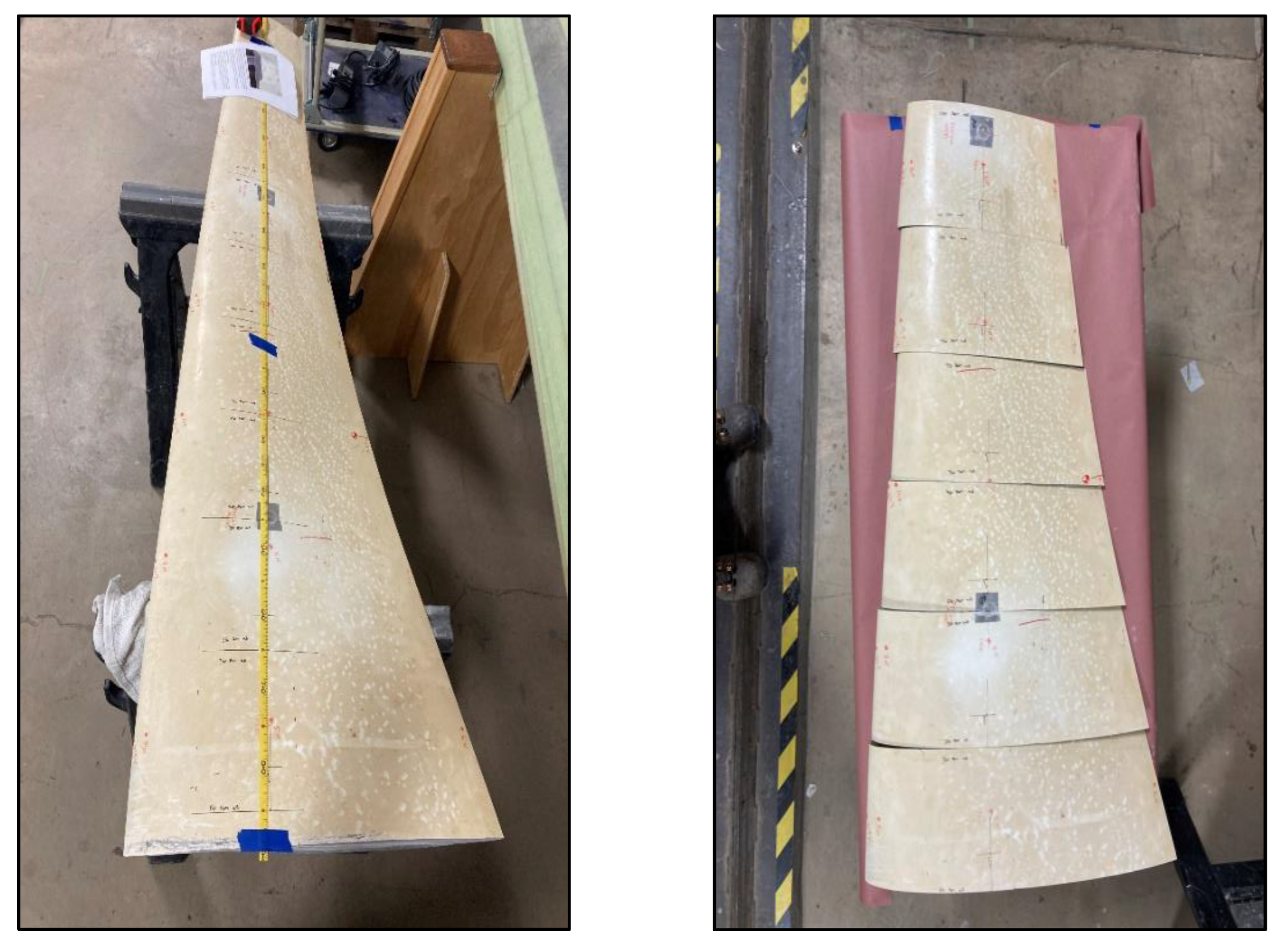
For this study, material characterization specimens were extracted from regions of the blade spar caps that had minimal curvature and no ply drops (discrete changes in the number of fiberglass layers where stress concentrations could occur), ensuring consistency and avoiding localized structural anomalies. The blades were first sectioned into 200 mm long segments using precision diamond saws to maintain cut quality, as shown in Figure 1. From these segments, tensile, dynamic mechanical analysis (DMA) and X-ray computed tomography (XCT) specimens were carefully machined, with dimensions tailored to relevant ASTM standards. All specimens were oriented along the primary fiber direction of the spar cap to accurately reflect in-plane material performance, as shown in Figure 2. Due to the high chord-wise curvature of the blade, transverse specimens did not meet ASTM standard dimensions and were not tested. This was deemed acceptable as the longitudinal properties of the spar cap laminate are the primary design consideration for this part of blades.
To assess the quality of the manufactured laminates, fiber volume fractions were measured for representative sections of both blade types using matrix burn-off techniques following ASTM D2584 Standard [22]. Typically, higher fiber volume fractions indicate higher quality laminates. The epoxy-based composite—despite being fabricated with prepreg materials, which typically yield higher fiber content—had a fiber volume fraction of 48.8% ± 0.3%. In contrast, the Elium-based thermoplastic blade, manufactured using vacuum-assisted resin transfer molding, exhibited a higher fiber volume fraction of 60.9% ± 1.5%. This result suggests that the infusion process led to effective fiber consolidation in the thermoplastic blade, while the epoxy blade may have retained excess resin due to limited bleed-off during autoclave curing.

2.2. Hygrothermal Aging

To evaluate the effects of moisture and temperature on composite behavior, a subset of the machined specimens underwent controlled hygrothermal conditioning. The test protocol was based on ASTM D5229 [23], which outlines procedures for assessing moisture absorption in polymer matrix composites under elevated temperatures. Following specimen preparation, the total population was divided into four equal groups and conditioned as outlined in Table 1.
One-quarter of the specimens were left in their as-fabricated (dry) state and stored for reference. Another quarter were submerged in distilled water at 50 °C for a period of 2 months. A third group was immersed in water at 50 °C for an extended duration of 4 months. The final quarter served as a dry thermal control group and was kept in a dry oven environment at 50 °C for 4 months.
All specimens were weighed before and after conditioning using an analytical balance with a precision of ±0.0001 g to track moisture uptake. To monitor water diffusion behavior more closely, a set of four specimens from each material from the 4-month immersion group were periodically removed and weighed throughout the conditioning period. These measurements were used to calculate Fickian diffusion coefficients and equilibrium moisture content, following the methodology outlined by Shen et al. [24].
In addition to the coupon-scale testing, full-length composite blades—one epoxy and one Elium—were conditioned under ambient 20 °C laboratory water immersion to better simulate real-world marine exposure. These full blades were weighed every 2 months using a precision scale (±0.1 g) to generate long-term absorption data, which can be used to validate diffusion modeling efforts and extrapolate expected saturation behavior over a multi-decade service life. Details of this can be found in [16] and are not repeated here; hence, all the results discussed in this paper are for the segmented coupons.

2.3. Dynamic Mechanical Analysis

DMA was used to determine the materials’ viscoelastic properties under dynamic conditions, specifically with varying temperature. The storage modulus, the loss modulus, and the tan delta were measured at temperatures from 20 °C (room temperature) to 180 °C to fully evaluate the materials properties before and after the glass transition temperature. The storage modulus is a measure of the energy stored elastically during deformation, the loss modulus is a measure of the energy converted to heat, and the tan delta is the ratio of loss modulus to storage modulus [25]. Eight wet and eight dry specimens (30 mm × 12 mm × 1 mm), were loaded into a TA Instruments DMA Q800 (sourced from New Castle, DE, USA) with single cantilever geometry. A preload of 0.1 N was applied to the mounted samples before a 20 μm, 1 Hz oscillation. Subsequently, the moduli and tan delta were measured as a function of temperature from 20 °C to 180 °C at 3 °C/min.

2.4. Tensile Characterization

To evaluate the effects of hygrothermal exposure on the mechanical performance of the composite materials, uniaxial tensile tests were conducted in accordance with ASTM D3039 [26]. Specimens were prepared from the spar caps of both blade types and cut to standardized dimensions of 175 mm × 15 mm × 1 mm. The specimens were aligned with the fiber direction to accurately capture the longitudinal tensile response.
Tensile testing was conducted on a 100 kN electro-mechanical load frame with hydraulic wedge grips and an Instron 8562 controller (sourced from Norwood, MA, USA). Testing was performed under displacement control using a constant crosshead speed of 1.2 mm/min until failure. A high-resolution extensometer was used to capture axial strain to determine elastic modulus from the linear portion of the stress–strain curve. The ultimate tensile strength was calculated by dividing the peak load at failure by the specimen’s cross-sectional area. Temperature and humidity were monitored and recorded during testing.

2.5. X-Ray Computed Tomography

XCT is a non-destructive imaging technique that was used to create detailed cross-sectional images of the composite specimens. This method was used to identify the general quality of the composite including detection of fiber misalignment, cracks, voids, or other defects. Two specimens were imaged using a Zeiss Xradia 620 Versa: fiberglass/Elium sample with dimensions of approximately 29 mm × 177 mm × 24.5 mm, and fiberglass/epoxy sample with dimensions of approximately 25 mm × 210 mm × 36 mm. A total of 3000 projections were collected over 360 degrees of rotation with an approximate exposure time of 1.6 s per projection for each sample. The X-ray source was set to 160 keV and 10 W power. The software Volume Graphics® 2023.4 was used to reconstruct the attenuation data that resulted in 1000 16-bit grayscale images with an image spatial resolution of 184.8 µm per voxel for the fiberglass/Elium sample and a spatial resolution of 233.8 µm per voxel for the fiber-glass/epoxy sample. Figure 3 shows representative image slices of the two samples obtained from XCT.
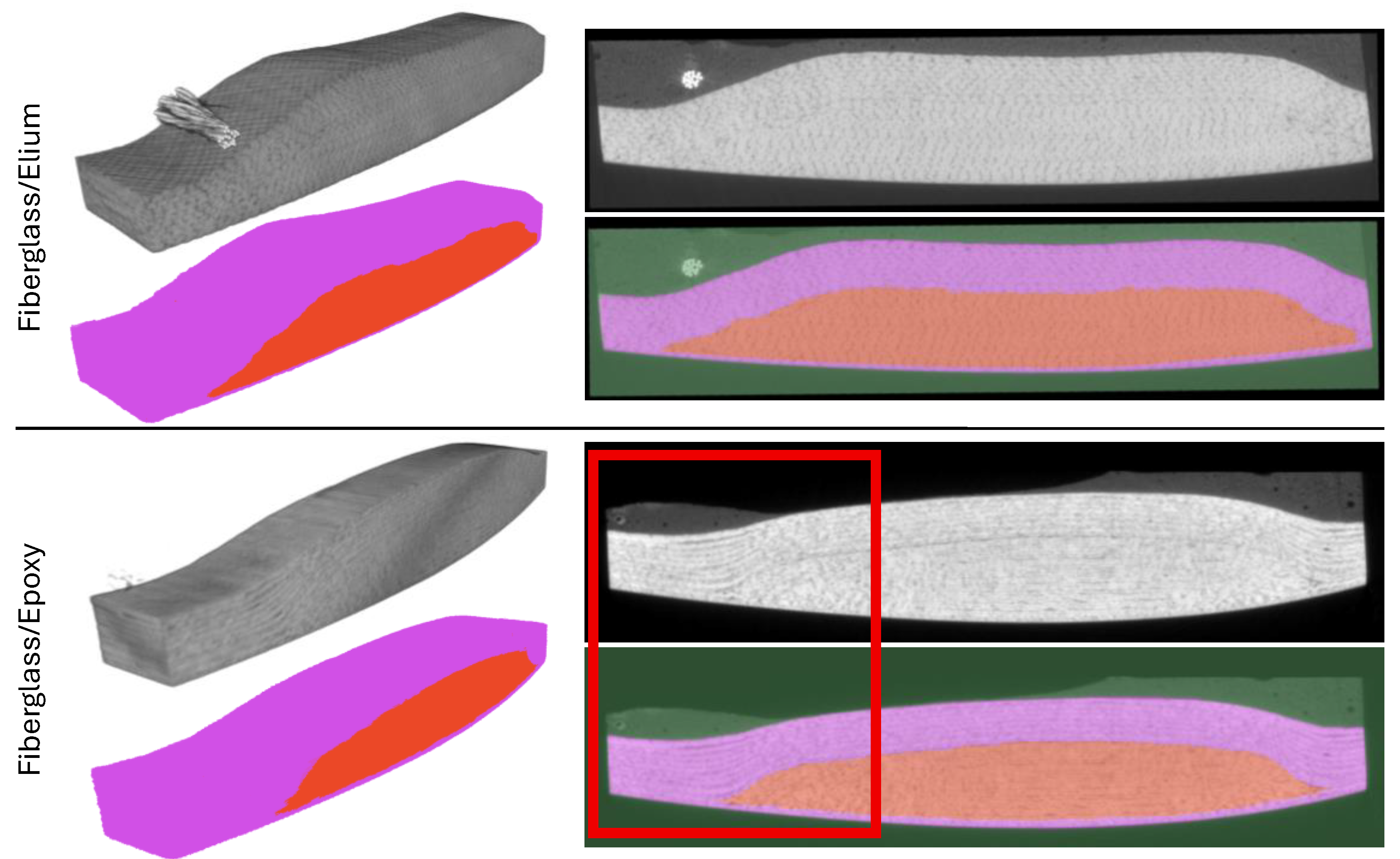
Image segmentation was performed to isolate the spar caps containing uni-directional plies from the skins containing alternating uni-directional and ±45° biaxial plies (i.e., plies that exhibit large curvature/undulation shown in Figure 3). Deep learning segmentation was performed using the software Dragonfly 2022.2 by Comet [27] with a 3D U-Net architecture a patch size of 32, a stride ratio of 0.15, a categorical cross entropy loss function, and the Adadelta optimization algorithm [28]. Default settings were leveraged apart from a decreased stride ratio with the goal of increased feature extraction between the spar caps and the skins. Training data was generated by manually labeling voxels within images into three classes: spar cap, skin, and background. Additional training data was generated by performing 10 data augmentation iterations through image flipping, scaling and adjusting brightness between 90% and 110% of their original size and intensity, and application of a small amount of Gaussian noise for a standard deviation between 0 and 0.01.
In total, approximately 9.3% of the total voxels were manually labeled for training before data augmentation for the fiberglass/epoxy dataset and approximately 3.2% for the fiberglass/Elium dataset. Evidence of convergence was observed within 25 epochs for the loss function and validation of the loss function for unseen data. A final segmentation step was performed to manually correct voxels that were misclassified resulting from deep learning segmentation.
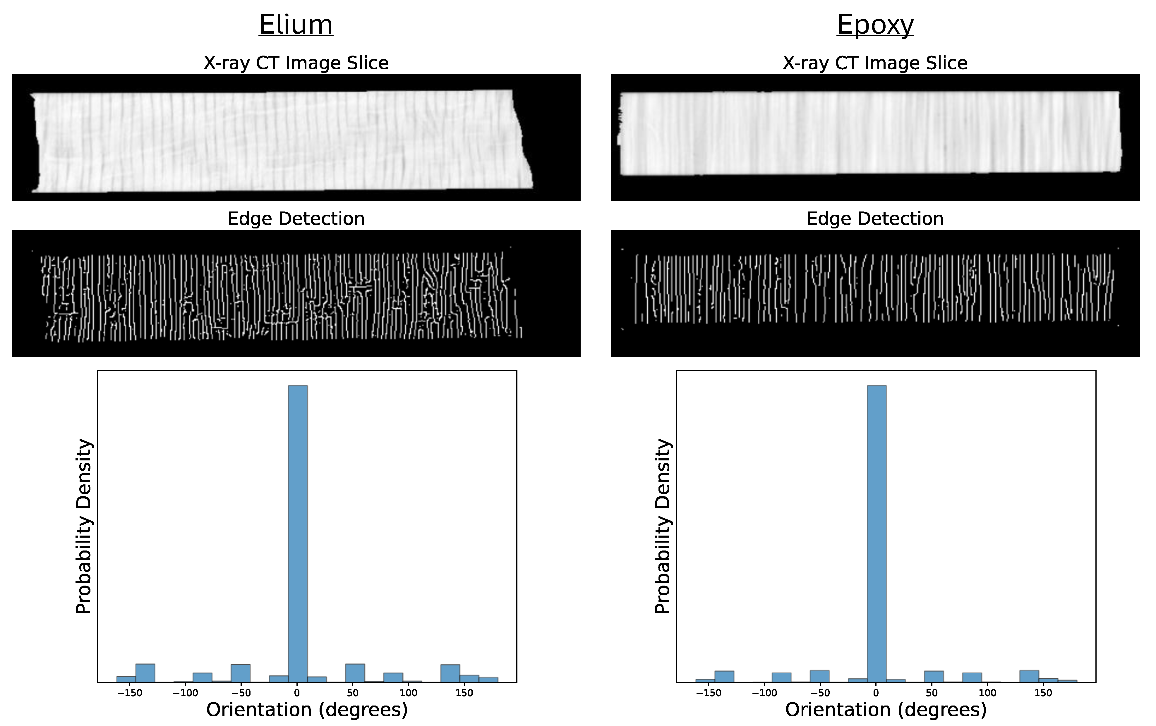
Individual fibers could not be discerned from the images due to the lower resolution. Estimates on orientation, however, were determined based on the edges of individual tows (i.e., tow/matrix interface). From the segmented images, edges of individual tows were determined using a Canny algorithm available in the open-source software Scikit-Image 0.22.0 [29]. A Gaussian filter with a standard deviation of 2 was used during edge detection. Then, horizontal and vertical edges were determined using Sobel transforms available within Scikit-Image. Finally, local orientations for individual voxels were extracted by calculating the arctangent of the Sobel edge maps. The above steps were repeated for each image in the stack.

3. Results and Discussion

3.1. Hygrothermal Aging Results

The results of hygrothermal aging are in [16] and summarized here to provide additional context to the expanded work. The average changes in mass among different batches of specimens exposed to various environmental conditions are compared in Figure 4. The control specimens experienced a measurable degree of desorption (weight loss) over the 4-month period in dry conditions at 50 °C. This suggests that the specimens had previously absorbed some moisture, though it remains unclear whether this resulted from submersion during the 6-month deployment at the Roosevelt Island Tidal Energy Project site or exposure to water during sectioning and cutting with wet saws.
The epoxy specimens exhibited an average mass increase of 0.76–0.78% over the 2–4-month period, with minimal variation (standard deviations of less than 0.04%) among individual samples. Additionally, the similarity in average mass changes between the 2- and 4-month periods suggests that full water saturation was reached before the end of the initial 2-month conditioning phase. Conversely, the Elium specimens displayed significant differences in mass changes between the 2- and 4-month batches, with an increase of 0.77% after 2 months and 0.54% after 4 months. There was notable variation between individual specimens, with standard deviations greater than 0.25%. The specimens in the 4-month batch showed a lower average mass increase compared to those conditioned for 2 months.
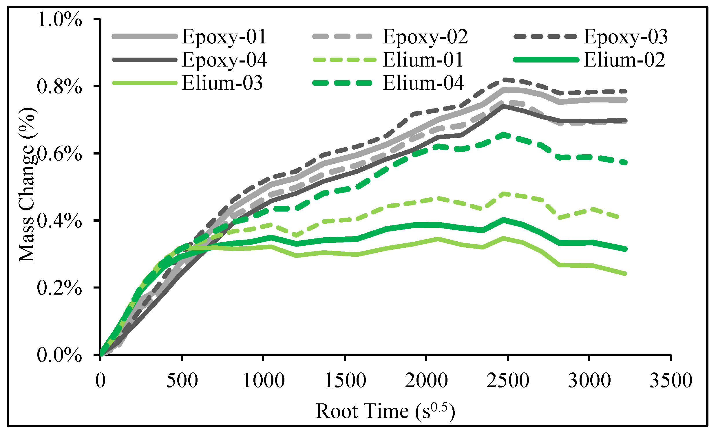
The lower average mass increase for the 4-month Elium batch (evident in Figure 5), compared to the 2-month batch, may be attributed to the leaching of unreacted monomers or the hydrolysis of ester bonds, both of which promote the extraction of molecules from the composite into the seawater [30]. The spar cap plies in the Elium blades contained 3% by area weight transverse backing tows, creating resin-rich regions between plies at the microscale, despite the overall higher fiber volume fraction observed at the macroscale. In contrast, the fibers in the epoxy blade’s spar caps were more evenly distributed and did not have these transverse backing tows, likely resulting in more consistent fiber volume fractions at the microscale. Since the specimens were cut along the laminate plane, some may have contained more resin than others, contributing to the observed variations.
Using the data presented in Figure 5, water diffusion properties were determined by assuming one-dimensional Fickian diffusion [24]. The maximum mass change was 0.776% ± 0.031% for epoxy and 0.471% ± 0.117% for Elium, and the diffusion coefficient (determined from the initial linear portion of the mass change/root time plot in Figure 5) was 2.10 ± 0.12 (×10−13) m2s−1 for epoxy and 12.1 ± 4.66 (×10−13) m2s−1 for Elium. The higher water uptake of the epoxy is expected given the structure of the polymers. The epoxy thermoset has stoichiometric tertiary amine bonds and stoichiometric hydroxyl groups which participate in hydrogen bonding and afford higher water uptake. Although the Elium specimens absorbed less water on average than the epoxy specimens, their diffusion coefficients were 5 times higher. This indicates that the Elium specimens reached full saturation in a shorter time. This is consistent with the dense epoxy crosslinked network being more difficult for water to penetrate than the thermoplastic analogue. This is a crucial factor when designing structures that must account for transient water diffusion and its impact on environmental degradation.

3.2. Dynamic Mechanical Analysis Results

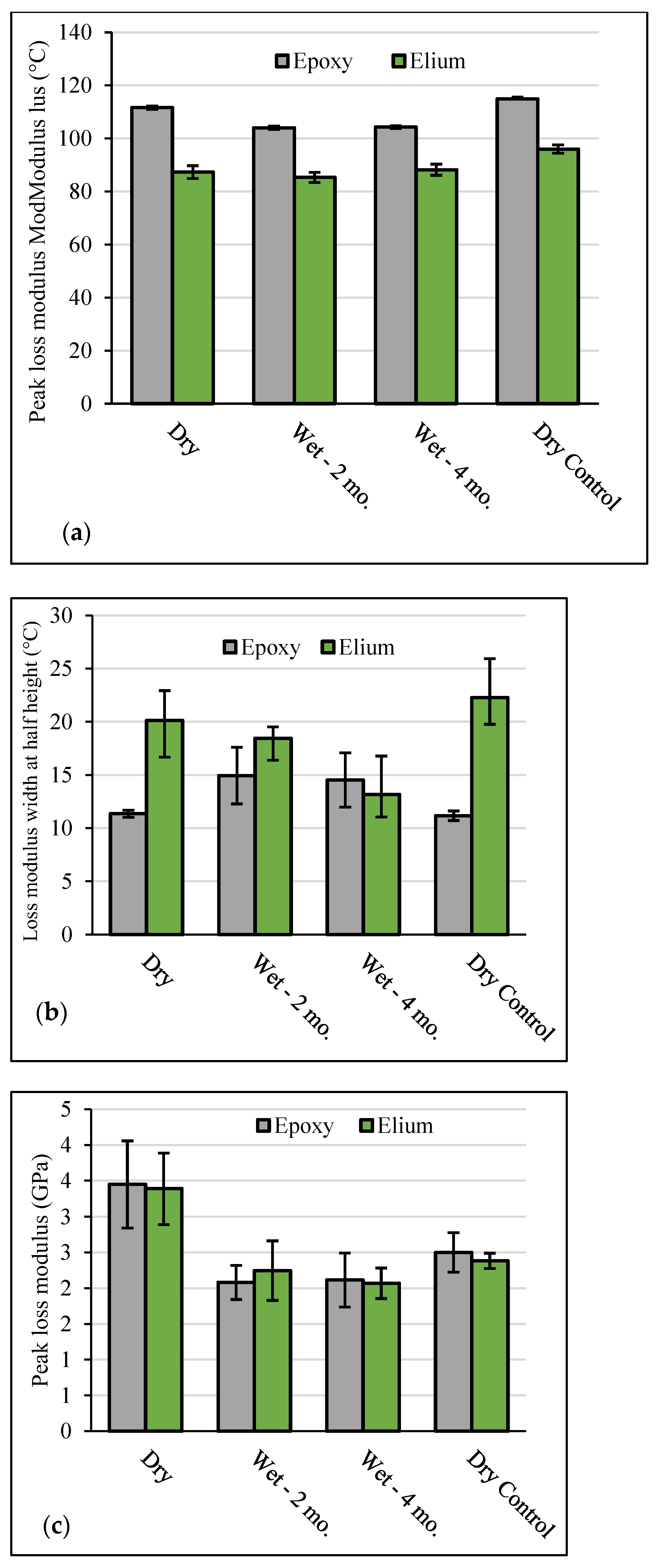
DMA was leveraged to analyze the hygrothermal aging of the polymer matrix within the post-deployed composites through analysis of the loss modulus. The loss modulus garners insight into the viscous response of the composite materials, which is largely a consequence of the molecular motions of the matrix polymer. After a dynamic heating experiment (~25 to 180 °C, 3 °C/min, 20 μm, 1 Hz) in single cantilever, the distribution of the loss modulus with respect to temperature was then quantified and is shown in Figure 6. Specifically, the distribution was quantified in three metrics: the temperature and the modulus value of the peak (the temperature and magnitude when energy loss is the greatest, respectively), and the temperature range of the loss modulus at half height (the temperature range when molecular motion is significantly observed).
The peak loss modulus temperature (Figure 6a) is one way to quantify the glass transition temperature (Tg). From these results, the Tg of both resin systems increases from the initial dry control to the 4-month aged dry control which is representative of residual aging or post-curing during this time interval (112 °C vs. 115 °C for the epoxy composites and 87 °C vs. 96 °C for the thermoplastic composites). However, the epoxy system exhibits a reduced Tg compared to the dry control that does not further diminish with continued underwater aging from 2 months to 4 months (112 °C vs. 104 °C vs. 104 °C). The reduced Tg in the epoxy composites can be attributed to water plasticizing the epoxy network and lowering the glass transition temperature, which is further supported by analyzing the loss modulus width at half height (middle). A significant broadening of the loss modulus distribution is observed as the network becomes less ordered from the water penetration (11.3 °C range from the control vs. 15 °C range for the wet tested samples).
Conversely, the thermoplastic samples do not exhibit reduced thermal performance after hygrothermal aging, as the glass transition temperatures are not statistically different from the dry control. In fact, the wet thermoplastic samples show a tighter temperature distribution of the loss modulus, or the viscous response of the material, suggesting that the polymer network is becoming more definite and ordered through continued underwater aging. This attribute is supported by the speculation above that while the thermoplastic composites absorb less water, small molecules and additives leaching out of the composite result in a less plasticized and more uniform polymer matrix. In both cases, the magnitude of the loss modulus peak (Figure 6b) decreases for the dried control, consistent with post-curing, and for the wet samples, which can be attributed to trapped water absorbing energy dissipation within the glass transition. Overall, hygrothermal aging impacts the thermal performance of both the thermoplastic and thermoset polymer matrix, to a greater extent than just thermal aging. Future MRE composites should be formulated for hydrophobicity to reduce the inclusion of excess, unbound additives.

3.3. Tensile Characterization Results

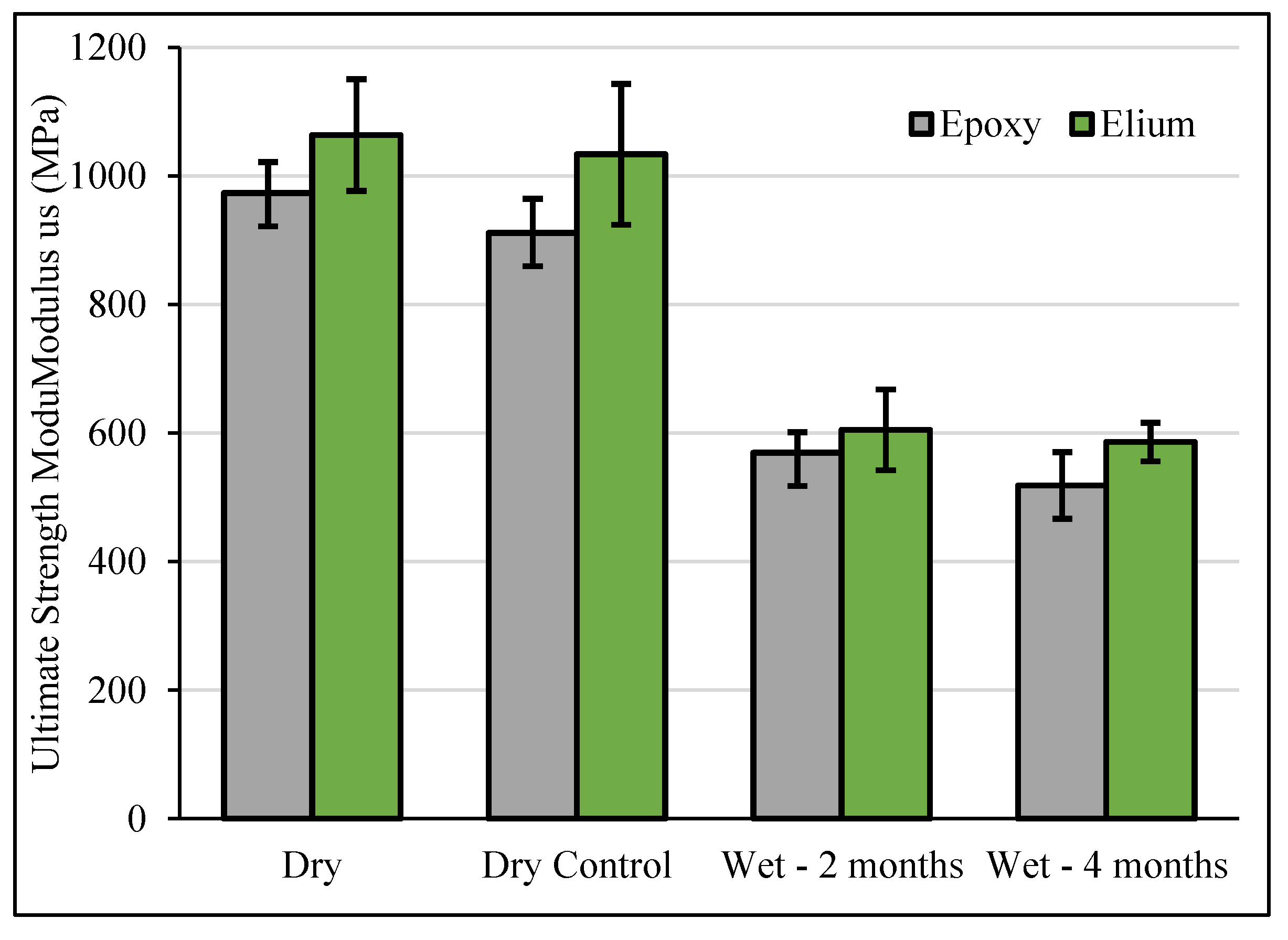
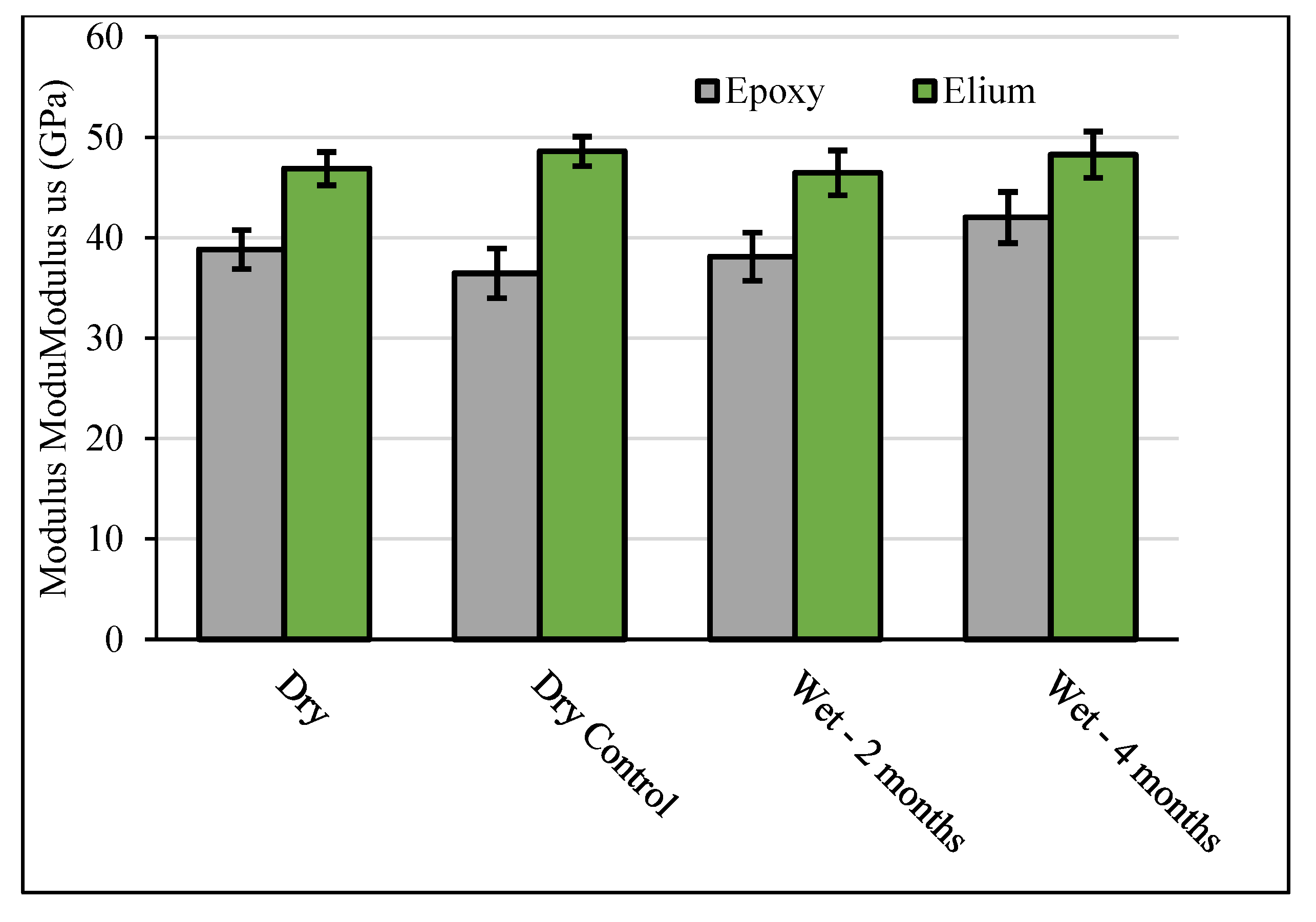
Figure 7 shows the ultimate strength, and Figure 8 shows the modulus from tensile testing as a function of aging conditions and materials. The Elium specimens had on average 9% higher ultimate strengths and on average 18% higher elastic modulus than the epoxy specimens, likely due to the higher fiber loading. The modulus was not significantly affected by hygrothermal aging. However, the tensile strength decreased by 42% for the 2-month epoxy specimens and 47% for the 4-month epoxy specimens and decreased by 43% for the 2-month Elium specimens and 45% for the 4-month Elium specimens.
This marked reduction in strength, despite stable modulus values, reflects the dominant role of the fiber network in controlling elastic behavior, whereas tensile strength is more sensitive to the matrix–fiber interface. At the macro-scale, all specimens for all hygrothermal aging and control groups of both epoxy and thermoplastic matrices exhibited similar failure modes—explosive and within the gage sections. For the epoxy composites, moisture ingress can lead to plasticization of the polymer matrix, in which absorbed water disrupts secondary bonding and increases molecular mobility. This impairs the matrix’s ability to transfer stress to the reinforcing fibers, resulting in diminished strength. Some degree of plastisization is also possible with the Elium composites, but here the marked reductions in strength could be due to solvation of necessary additives that improve the thermoplastics performance and importantly, the matrix–fiber interface.
In addition to plasticization, hydrolytic degradation (the chemical breakdown of a material caused by reaction with water) may occur, particularly in resins containing reactive functional groups. Epoxy systems cured with amine hardeners can undergo hydrolysis at unreacted amine sites, while acrylic-based thermoplastics like Elium may degrade at ester linkages. Hydrolysis generates hydrophilic groups, leading to resin swelling and further mechanical softening.

3.4. X-Ray Computed Tomography Results

The results from the image segmentation steps outlined in Section 2.5 are shown in Figure 9. In these images, renderings of the image data in both 3D (left) and 2D (right) are shown with corresponding segmentation results for the fiberglass/Elium composite (top) and the fiberglass/epoxy (bottom). The segmentation colors for pink, red, and green for 2D correspond to the skin, spar cap, and background, respectively. Visual inspection of the image data showed no evidence of cracks, large defects, or large resin-rich regions for both samples. For the fiberglass/epoxy, evidence of incomplete compaction between layers can be seen from Figure 9 where ply separation is observed in regions of increased curvature towards the left and right edges as shown.
The above results indicate qualitatively that the quality of both composite systems was high after manufacturing. Furthermore, Figure 10 shows the results from calculating the local orientation. The top row shows a representative image slice where the skin and background were colored black, the middle row shows the results from edge detection, and the bottom row shows the probability density distribution of extracted local orientations. Note that an orientation of “0 degrees” corresponds to a vertical orientation shown in the representative image slices.
From these results, overall misalignment in tow edge orientation was minimal. Slightly higher misalignment can be determined for the fiberglass/Elium composite compared to the fiberglass/epoxy composite. Evidence of misalignment for fiberglass/Elium can be seen in Figure 10 where the edges of horizontal striations were detected. However, these occurrences do not significantly skew the distribution.
Overall, analysis of the XCT images showed that both composites were manufactured with high quality: no large voids or cracks were present, and the degree of misalignment was low. The above analysis was only performed on one sample from each resin type studied. However, based on the good quality of the samples investigated through image analysis, it is anticipated that similar results would be obtained for other samples examined in this study. Furthermore, the high-quality in sample manufacturing suggests that sample-to-sample variability for mechanical results is likely to be low, which can be observed from Figure 6, Figure 7 and Figure 8. Spread in measurement distributions likely stems from matrix or fiber–matrix dominated effects compared to mechanical behavior of the fibers alone.
Further insights can be taken from the resulting architecture captured via XCT to answer competing mechanism on diffusion effects. It was noted from Figure 5 that the fiberglass/Elium blades exhibited greater diffusion compared to their epoxy counterpart. Besides the inherent differences in water uptake between thermoset and thermoplastics, the underlying architecture likely plays a role on diffusion rates. The fiberglass/Elium blades consist of individual tows of fiber glass within a given ply. Gaps between tows are larger and longer compared to gaps observed from the fiberglass/epoxy blades (e.g., dark gray regions shown in Figure 10). These larger gaps provide preferential pathways for water to diffuse into the composite, which leads to higher diffusion coefficients. For the fiberglass/epoxy blades, the increased tortuosity of individual fibers and the surrounding epoxy likely leads to lower diffusion coefficients.

4. Conclusions

This study provides an in-depth evaluation of the hygrothermal response and thermomechanical behavior of as-manufactured glass fiber-reinforced epoxy and thermoplastic (Elium®) tidal turbine blades. Through a combination of accelerated conditioning, mechanical testing, and material characterization, differences in water absorption, diffusion behavior, and strength retention between the two composite systems were identified.
Material characterization through X-ray computed tomography (XCT) showed that both composite turbine blades had little evidence of manufacturing-induced defects and minimal fiber misalignment. While epoxy composites demonstrated more consistent water uptake and superior resistance to early-stage diffusion, the Elium-based thermoplastic laminates showed higher thermal property retention, albeit with significantly faster moisture ingress and greater variability. Furthermore, evidence from XCT showed increased matrix gaps between tows, which likely contributed to the increased moisture ingress compared to the epoxy composites. Importantly, both material systems suffered substantial reductions in tensile strength—exceeding 40%—following prolonged water exposure, emphasizing the vulnerability of fiber–matrix interfaces to moisture-induced degradation, even when elastic moduli appeared unaffected. No statistical changes in moduli were observed for both the epoxy and thermoplastic composites due to hygrothermal aging. This implied that strength degradation was due to degradation of the matrices and fiber/matrix interfaces and not the fibers themselves. Additionally, the DMA results showed that glass transition temperature for was reduced for the epoxy composite specimens and unaffected for the thermoplastic composite specimens, indicating that the hygrothermal aging process had a greater impact on the viscoelastic properties of the epoxy composites.
These findings carry significant implications for the MRE industry. Material systems must not only perform structurally under demanding loads but must also maintain their integrity in harsh, high-moisture environments over extended service lives. This study reinforces the importance of integrating environmental durability into early-stage design decisions, and it highlights the need for advanced resin formulations, robust manufacturing controls, and protective surface treatments. As the MRE sector continues to mature, the insights from this work will help developers make informed choices in material selection, improve predictive models for long-term degradation, and ultimately support the deployment of more resilient, reliable tidal energy systems.
Author Contributions

Conceptualization, P.M. and R.E.M.; Validation, D.B., A.F.L., P.J.C. and D.S.; Formal analysis, A.F.L., E.G.R., P.J.C. and D.S.; Investigation, P.M. and P.J.C.; Data curation, P.M., A.F.L. and E.G.R.; Writing—original draft, P.M. and R.E.M.; Writing—review & editing, P.M., R.E.M., A.F.L., E.G.R. and P.J.C.; Project administration, P.M. and R.E.M.; Funding acquisition, P.M. and R.E.M. All authors have read and agreed to the published version of the manuscript.

Funding

Funding provided for this work by USA Department of Energy Office of Energy Efficiency and Renewable Energy Water Power Technologies Office. Grant Number: DE-AC36-08GO28308.

Data Availability Statement

The data presented in this study are available on request from the corresponding author.

Conflicts of Interest

The authors declare no conflicts of interest.

Disclaimer

This work was authored by the National Renewable Energy Laboratory for the USA Department of Energy (DOE) and by Sandia National Laboratories. Sandia National Laboratories is a multi-mission laboratory managed and operated by National Technology & Engineering Solutions of Sandia, LLC, a wholly owned subsidiary of Honeywell International Inc., for the USA Department of Energy’s National Nuclear Security Administration under contract DE-NA0003525. This paper describes objective technical results and analysis. Any subjective views or opinions that might be expressed in the paper do not necessarily represent the views of the USA Department of Energy or the United States Government. The publisher, by accepting the article for publication, acknowledges that the USA Government retains a nonexclusive, paid-up, irrevocable, worldwide license to publish or reproduce the published form of this work, or allow others to do so, for USA Government purposes.

Abbreviations

The following abbreviations are used in this manuscript:
TgGlass transition temperature
NRELNational Renewable Energy Laboratory
DMADynamic mechanical analysis
MREMarine renewable energy
XCTX-ray computed tomography

References

  1. Haas, K.A.; Fritz, H.M.; French, S.P.; Smith, B.T.; Neary, V. Assessment of Energy Production Potential from Tidal Streams in the United States; Georgia Institute of Technology: Atlanta, GA, USA, 2011; p. 109. [Google Scholar]
  2. Hagerman, G.; Scott, G.; Jacobson, P.T. Mapping and Assessment of the United States Ocean Wave Energy Resource; Electric Power Research Institute (EPRI): Palo Alto, CA, USA, 2011; p. 176. [Google Scholar]
  3. Kazimierczuk, K.; Henderson, C.; Duffy, K.; Hanif, S.; Bhattacharya, S.; Biswas, S.; Jacroux, E.; Preziuso, D.; Wu, D.; Bhatnagar, D.; et al. A socio-technical assessment of marine renewable energy potential in coastal communities. Energy Res. Soc. Sci. 2023, 100, 103098. [Google Scholar] [CrossRef]
  4. U.S. Department of Energy. Powering the Blue Economy: Exploring Opportunities for Marine Renewable Energy in Maritime Markets; EERE Publication and Product Library: Washington, DC, USA, 2022; p. 11.
  5. Kennedy, C.R.; Jaksic, V.; Leen, S.B.; Ó Brádaigh, C.M. Fatigue life of pitch- and stall-regulated composite tidal turbine blades. Renew. Energy 2018, 121, 688–699. [Google Scholar] [CrossRef]
  6. Yu, Y.H.; Jenne, D.S.; Thresher, R.; Copping, A.; Geerlofs, S.; Hanna, L.A. Reference Model 5 (RM5): Oscillating Surge Wave Energy Converter; National Renewable Energy Laboratory (NREL): Golden, CO, USA, 2015; p. 48.
  7. Aceti, P.; Carminati, L.; Bettini, P.; Sala, G. Hygrothermal ageing of composite structures. Part 1: Technical review. Compos. Struct. 2023, 319, 117076. [Google Scholar] [CrossRef]
  8. Alam, P.; Robert, C.; Ó Brádaigh, C.M. Tidal turbine blade composites—A review on the effects of hygrothermal aging on the properties of CFRP. Compos. Part B Eng. 2018, 149, 248–259. [Google Scholar] [CrossRef]
  9. Davies, P. Evaluation of New Composite Materials for Marine Applications. Appl. Compos. Mater. 2024, 31, 1933–1954. [Google Scholar] [CrossRef]
  10. Miller, D.A.; Samborsky, D.D.; Stoffels, M.T.; Voth, M.M.; Nunemaker, J.D.; Newhouse, K.J.; Hernandez-Sanchez, B.A. Summary of Marine and Hydrokinetic (MHK) Composites Testing at Montana State University; Sandia National Laboratories (SNL-NM): Albuquerque, NM, USA; Montana State University: Bozeman, MT, USA, 2020; p. 153.
  11. Davies, P.; Arhant, M. Fatigue Behaviour of Acrylic Matrix Composites: Influence of Seawater. Appl. Compos. Mater. 2019, 26, 507–518. [Google Scholar] [CrossRef]
  12. Murdy, P.; Hughes, S.; Miller, D.A.; Presuel-Moreno, F.J.; Bonheyo, G.T.; Gunawan, B.; Hernandez-Sanchez, B.A. Static and Fatigue Characterization of Large Composite T-Bolt Connections in Marine Hygrothermal Environments. J. Mar. Sci. Eng. 2023, 11, 2309. [Google Scholar] [CrossRef]
  13. Devine, M.; Bajpai, A.; Obande, W.; Ó Brádaigh, C.M.; Ray, D. Seawater ageing of thermoplastic acrylic hybrid matrix composites for marine applications. Compos. Part B Eng. 2023, 263, 110879. [Google Scholar] [CrossRef]
  14. Alsaadi, M.; Flanagan, T.; Fitzpatrick, D.P.; Devine, D.M. The Delamination Behaviour of Basalt Fibre-Reinforced In Situ-Polymerisable Acrylic and Epoxy Composites: A Sustainable Solution for Marine Applications. Sustainability 2025, 17, 6967. [Google Scholar] [CrossRef]
  15. Finnegan, W.; Jiang, Y.; Meier, P.; Hung, L.C.; Fagan, E.; Wallace, F.; Glennon, C.; Flanagan, M.; Flanagan, T.; Goggins, J. Numerical modelling, manufacture and structural testing of a full-scale 1 MW tidal turbine blade. Ocean. Eng. 2022, 266, 112717. [Google Scholar] [CrossRef]
  16. Murdy, P.; Lusty, A.; Murray, R.; Hughes, S.; Beach, R. Post-Deployment Characterization of Glass Fiber-Reinforced Thermoset and Thermoplastic Composite Tidal Turbine Blades. In Proceedings of the Society for the Advancement of Material and Process Engineering, Long Beach, CA, USA, 20–23 May 2024. [Google Scholar]
  17. Bandaru, A.K.; Hickey, S.; Singh, D.; Gujjala, R.; Pichandi, S. Influence of hygrothermal ageing on the novel infusible thermoplastic resin reinforced with quadriaxial non-crimp glass fabrics. J. Thermoplast. Compos. Mater. 2022, 36, 3813–3836. [Google Scholar] [CrossRef]
  18. Finnegan, W.; Jiang, Y.; Flanagan, M.; Goggins, J. Observations from structural testing of full-scale tidal turbine blades. Int. Mar. Energy J. 2025, 8, 247–251. [Google Scholar] [CrossRef]
  19. Cousins, D.S.; Suzukia, Y.; Murray, R.E.; Samaniuk, J.R.; Stebner, A.P. Recycling glass fiber thermoplastic composites from wind turbine blades. J. Clean. Prod. 2018, 209, 1252–1263. [Google Scholar] [CrossRef]
  20. Murray, R.E.; Beach, R.; Murdy, P.; Dana, S.; Hughes, S. Structural Characterization of Deployed Thermoplastic and Thermoset Composite Tidal Turbine Blades; National Renewable Energy Laboratory (NREL): Golden, CO, USA, 2024; p. 27.
  21. Murray, R.E.; Simms, A.; Bharath, A.; Beach, R.; Murphy, M.; Kilcher, L.; Scholbrock, A. Toward the Instrumentation and Data Acquisition of a Tidal Turbine in Real Site Conditions. Energies 2023, 16, 1255. [Google Scholar] [CrossRef]
  22. ASTM D2584-18; Standard Test Method for Ignition Loss of Cured Reinforced Resins. ASTM International: West Conshohocken, PA, USA, 2018.
  23. ASTM D5229; Standard Test Method for Moisture Absorption Properties and Equilibrium Conditioning of Polymer Matrix Composite Materials. ASTM International: West Conshohocken, PA, USA, 2012.
  24. Shen, C.-H.; Springer, G.S. Moisture Absorption and Desorption of Composite Materials. J. Compos. Mater. 1976, 10, 2–20. [Google Scholar] [CrossRef]
  25. Sperling, L.H. Introduction to Physical Polymer Science; John Wiley & Sons: Hoboken, NJ, USA, 2006. [Google Scholar] [CrossRef]
  26. ASTM D3039/D3039M-08; Standard Test Method for Tensile Properties of Polymer Matrix Composite Materials. ASTM International: West Conshohocken, PA, USA, 2014.
  27. Makovetsky, R.; Piche, N.; Marsh, M. Dragonfly as a platform for easy image-based deep learning applications. Microsc. Microanal. 2018, 24, 532–533. [Google Scholar] [CrossRef]
  28. Zeiler, M.D. ADADELTA: An Adaptive Learning Rate Method. Available online: https://arxiv.org/abs/1212.5701 (accessed on 7 July 2025).
  29. Van der Walt, S.; Schönberger, J.L.; Nunez-Iglesias, J.; Boulogne, F.; Warner, J.D.; Yager, N.; Gouillart, E.; Yu, T. Scikit-image: Image processing in Python. PeerJ 2014, 2, e453. [Google Scholar] [CrossRef] [PubMed]
  30. Kootsookos, A.; Mouritz, A.P. Seawater durability of glass- and carbon-polymer composites. Compos. Sci. Technol. 2004, 64, 1503–1511. [Google Scholar] [CrossRef]
Figure 1. A fiberglass/epoxy Verdant blade following a 6-month deployment in the East River, New York (left), and the same blade after being sectioned into 200 mm segments for subsequent material characterization (right).
Jmse 13 01790 g001
Figure 2. Photo of blade with schematic illustrating how specimens were cut from the blade spar caps, demonstrated on a non-deployed blade (left), and the resulting epoxy and Elium specimens arranged after sectioning (right).
Jmse 13 01790 g002
Figure 3. Representative X-ray cross section image slices of the fiberglass/Elium (top) and fiberglass/epoxy (bottom) Verdant blade samples.
Jmse 13 01790 g003
Figure 4. Average changes in masses of all specimens subjected to environmental conditioning. Error bars showing +/− one standard deviation.
Jmse 13 01790 g004
Figure 5. Mass changes against square root of time for the specimens (labeled-01 through-04) that had their masses measured periodically throughout the 4-month conditioning period.
Jmse 13 01790 g005
Figure 6. DMA results showing peak loss modulus temperature (a), the loss modulus width at half height (b), and the magnitude of the loss modulus (c) for non-tested control (Dry), hygrothermally aged for 2 months (Wet-2mo.), hygrothermally aged for 4 months (Wet-4mo.), and dry aged composites for 4 months (Dry Control).
Jmse 13 01790 g006
Figure 7. Elium and epoxy tensile ultimate strength for the four aging scenarios: dry and untested (dry), submerged in water at 50 °C for 2 months (wet-2 months), submerged in water at 50 °C for 4 months (wet-4 months), and kept dry at 50 °C for 4 months (dry control).
Jmse 13 01790 g007
Figure 8. Elium and epoxy tensile modulus for the four aging scenarios: dry and untested (dry), submerged in water at 50 °C for 2 months (wet-2 months), submerged in water at 50 °C for 4 months (wet-4 months), and kept dry at 50 °C for 4 months (dry control).
Jmse 13 01790 g008
Figure 9. Segmentation results for the fiberglass/Elium (top) and fiberglass/epoxy (bottom) Verdant blade samples for 3D orientations (left) and 2D image slices (right). Ply separation is seen as a defect in the epoxy cross-section, indicated by the red box.
Jmse 13 01790 g009
Figure 10. Edge detection results to determine local tow orientation for the fiberglass/Elium (left) and the fiberglass/epoxy (right) verdant blade samples. Histograms show distribution of local gradients/orientations calculated for the entire image stack. The top row shows a representative image slice where the skin and background were colored black, the middle row shows the results from edge detection, and the bottom row shows the probability density distribution of extracted local orientations.
Jmse 13 01790 g010
Table 1. Specimen conditioning protocols (quantities for each material).
NameSpecimen QuantityTemperatureStorage ConditionDuration
Dry820 °CDry storage4 months
Wet-2 month850 °CSubmerged in water2 months
Wet-4 month850 °CSubmerged in water4 months
Dry-control850 °CDry oven4 months
Disclaimer/Publisher’s Note: The statements, opinions and data contained in all publications are solely those of the individual author(s) and contributor(s) and not of MDPI and/or the editor(s). MDPI and/or the editor(s) disclaim responsibility for any injury to people or property resulting from any ideas, methods, instructions or products referred to in the content.