Article

Adaptive Fuzzy Sliding-Mode Control for Ship Path Tracking Based on a Fixed-Time Disturbance Observer

College of Aeronautics, Inner Mongolia University of Technology, Hohhot 010051, China
*
Author to whom correspondence should be addressed.
J. Mar. Sci. Eng. 2025, 13(9), 1788; https://doi.org/10.3390/jmse13091788
Submission received: 22 August 2025 / Revised: 13 September 2025 / Accepted: 13 September 2025 / Published: 16 September 2025
(This article belongs to the Section Ocean Engineering)

Abstract

We propose a control method that integrates adaptive fuzzy sliding-mode control (AF-SMC) with a fixed-time disturbance observer (FTDO) to address modeling errors, external disturbances, and input saturation in ship path tracking. The designed adaptive fuzzy system dynamically adjusts the SMC gain to enhance adaptability to parameter variations and modeling errors. Furthermore, the proposed method enables rapid estimation of the total uncertainty term by incorporating an FTDO, ensuring fixed-time estimation and feedforward compensation of the total matched uncertainty without requiring prior knowledge of the disturbance bound. Lyapunov stability analysis was employed to verify the bounded stability of the closed-loop system. Simulation results indicate that the proposed method provides high control accuracy and robustness.

1. Introduction

A ship’s path tracking capability directly affects the safety and intelligence level of navigation in marine transportation and operations. Ships encounter disturbances from complex sea conditions, such as wind, waves, and currents, along with issues including inaccurate modeling, strong system nonlinearity, and high parameter uncertainty, disturbing ship path tracking. In particular, traditional control methods fall short of delivering high stability, real-time performance, and robustness in scenarios such as ocean-going voyages or precision operations. Therefore, the suppression of trajectory deviations and external disturbances must be improved while ensuring high response performance in intelligent ship control [1,2].
Extensive studies have been conducted to address modeling uncertainty, external disturbances, and input saturation in ship path tracking using observer design, intelligent approximation algorithms, and control strategy optimization. For example, extended state observers have been introduced to simultaneously estimate disturbances and unmodeled dynamics, which enhanced system robustness [3,4]; fuzzy logic systems, neural networks, and minimal learning parameters have been employed to approximate system uncertainties and improve adaptability to complex sea conditions [5,6]; and nonlinear observers have been combined with model predictive control to achieve precise maneuvering under input constraints [7,8]. In addition, event-triggered mechanisms have been applied to path tracking control considering limitations on control frequency and energy consumption to reduce control update frequency while maintaining performance [9].
Recently, ensuring rapid convergence of system states within a finite time while maintaining control accuracy under nonlinearities, disturbances, and constraints has become crucial. Fixed-time control methods have been proposed and gradually applied to ship attitude regulation and path tracking tasks to precisely regulate the convergence time in sliding-mode control (SMC), and time-bounded stability independent of initial conditions has been achieved [10,11]. Meanwhile, fuzzy logic has been incorporated into SMC systems to mitigate sliding-mode chattering and improve system flexibility, thereby providing approximate compensation for unknown dynamics [12,13]. In practical engineering, researchers have further introduced event-triggered mechanisms into sliding-mode systems to balance performance and execution efficiency. These methods effectively reduce control update frequency by designing appropriate triggering conditions, thereby lowering energy consumption and alleviating rudder wear while maintaining system stability and convergence performance [14,15].
Improving disturbance estimation accuracy and nonlinear compensation capability has become a key direction in controller design. While one line of research combines improved disturbance observers with sliding-mode strategies to enhance the total uncertainty estimation accuracy without introducing additional switching functions [16], another leverages neural network structures to achieve adaptive learning and dynamic compensation for multisource unknown disturbances [17]. Fuzzy systems are often integrated into SMC frameworks to further enhance robustness in dynamically changing environments, alleviate sliding-mode chattering, and improve dynamic performance [18]. Event-triggered SMC can reduce update frequency and resource consumption through well-designed triggering conditions in scenarios with limited control execution frequency [19,20]. Moreover, adaptive observers have been designed based on prescribed performance functions to balance disturbance estimation accuracy and convergence speed; this ensured that the observation error has met predefined dynamic bounds while offering improved transient controllability [21,22].
In this study, we designed a control method that integrates adaptive fuzzy SMC (AF-SMC) with a fixed-time disturbance observer (FTDO) to address modeling uncertainties and disturbance suppression in ship path tracking. First, an adaptive gain adjustment mechanism was incorporated into the SMC framework, which dynamically tuned the control gain according to system state errors to improve adaptability to model parameter variations and external disturbances. Second, a fuzzy system was used for nonlinear compensation of the sliding-mode reaching law, and chattering was suppressed while enhancing control accuracy. Finally, a disturbance observer with a prescribed convergence time was designed for rapid and accurate estimation and feedforward compensation of the total uncertainty term. In the controller design process, both input constraints and system stability were considered, a complete control law was constructed, and Lyapunov theory was applied to prove the bounded stability of the closed-loop system. The remainder of this paper is organized as follows: the mathematical model for ship path tracking is described in Section 2; the SMC algorithm design based on the FTDO is detailed in Section 3; simulation experiments and comparative performance analysis are presented in Section 4; and the conclusions are summarized in Section 5.

2. Mathematical Model

2.1. Path Tracking Error Modeling

This section primarily describes the control of a ship along a preset reference trajectory.
As shown in Figure 1, the Earth-fixed and body-fixed coordinate frames are established, and the cross-track position error and heading error are defined to characterize the vessel’s deviation from the reference trajectory. It is assumed that the path to be tracked comprises a series of vertices (turning points), with each point on the path defined as follows:
p 1 x 1 , y 1 , p 2 x 2 , y 2 , , p i x i , y i , , p n x n , y n
Coordinate transformation is performed using
x r y r ψ r = cos φ i sin φ i 0 sin φ i cos φ i 0 0 0 1 x g x i y g y i ψ φ i .
where x g , y g are the ship coordinates in the geodetic coordinate system, x r , y r are the ship coordinates in the relative coordinate system, φ i is the heading angle of the reference path at the reference point p i , and ψ r is the heading error between the ship heading and the reference path.
The error variables are defined as follows:
η e = e y e ψ = y r ψ r .

2.2. Ship Motion Model

The Maneuvering Modeling Group (MMG) model is widely used in simulation experiments owing to its high accuracy. The ship simulation model adopted in this study is described in [6], and its form is given by
x ˙ = u cos ψ v sin ψ y ˙ = u sin ψ + v cos ψ ψ ˙ = r u ˙ = 1 m + m x m + m y v r + X H + X P + X W + X W A V E + m x m y V c sin ψ c ψ r v ˙ = 1 m + m y m + m x u r + Y H + Y P + Y W + Y W A V E + m x m y V c cos ψ c ψ r r ˙ = 1 I Z Z + J Z Z N H + N P + N R + N W + N W A V E ,
where u , v , and r are the surge velocity, sway velocity, and yaw rate, respectively, and ψ denotes the ship’s heading angle. m is the ship mass; m x and m y are the added masses; X H , Y H , and N H are the hydrodynamic forces (moments) of the bare hull; X P , Y P , and N P are the propeller forces (moments); ψ C and V C denote the current direction and speed, respectively; X W , Y W , and N W represent the wind forces (moments); X W A V E , Y W A V E , and N W A V E represent the wave forces (moments); I Z Z is the moment of inertia of the ship about the vertical axis; and J Z Z is the added moment of inertia.
Direct use of the MMG model for controller design is challenging owing to its highly nonlinear nature and the presence of multiple unmeasurable disturbance components. Thus, we adopted the Nomoto model as the controller design model to simplify the controller design and align with navigational practice, which can be expressed as follows [7]:
x ˙ = u cos ψ v sin ψ = u 2 + v 2 cos ψ + β y ˙ = u sin ψ + v cos ψ = u 2 + v 2 sin ψ + β ψ ˙ = r r ˙ = r T + K T δ + f r β = arctan v / u ,
where K is the turning ability index, T is the turning lag index, δ is the rudder angle, β is the sideslip angle, and f r represents the external uncertain disturbance.

3. Controller Design

Two key indicators affect ship path tracking accuracy: the cross-track position error and the heading-angle error. These errors may be amplified in the dynamic response if not effectively compensated in the presence of external disturbances, such as wind, waves, and currents, as well as uncertainties in the ship’s dynamic model. This degrades control performance or even causes trajectory divergence.
Thus, we incorporated an adaptive mechanism and the fuzzy logic system into the SMC framework to dynamically adjust the control gain and suppress chattering, thereby achieving both fast convergence and satisfactory steady-state performance. Simultaneously, we designed an FTDO to rapidly estimate the total uncertainty term and provide feedforward compensation, effectively enhancing the disturbance rejection capability and adaptability of the ship path tracking system.

3.1. Adaptive Fuzzy Sliding-Mode Controller

In ship path tracking, coordinated convergence of the cross-track position error and the heading-angle error is required. Thus, the error variables are converged to zero:
e y = y r ,   e ψ = ψ r .
A first-order sliding surface is constructed in the following form:
s = λ 1 e y + λ 2 e ψ + λ 3 e ˙ ψ .
Here, λ i > 0 is a constant weight used to balance the contributions of the cross-track position error and the heading-angle error in the sliding surface.
Differentiating the sliding surface s yields
s ˙ = λ 1 e ˙ y + λ 2 e ˙ ψ + λ 3 e ¨ ψ .
Because we mainly considered the heading-angle and cross-track position errors during the ship’s motion along the path, and x r represents the motion along the path direction, the first kinematic equation in the ship motion model was omitted. Combining the ship motion model with the path tracking error model gives the following linearized approximation equation:
e ˙ y = y ˙ r = u e ψ + v + d y e ˙ ψ = ψ ˙ r = r ,
where d y is the modeling error.
Therefore, the derivative of the sliding surface s can be written as
s ˙ = λ 1 u e ψ + v + λ 2 r + λ 3 r ˙ + λ 1 d y .
Substituting the ship’s yaw rate model (4) into (9) yields
s ˙ = A + B δ + Δ ,
where A = λ 1 u e ψ + v + λ 2 r λ 3 T r , B = λ 3 K T , Δ is the total matched uncertainty term, and d y is the linear combination of the modeling error and the external disturbance f r .
To ensure that the sliding surface s can converge in finite time while reducing chattering, the following reaching law was adopted:
s ˙ = k s s h s i g n s ρ tanh s ε ,
where k s > 0 and ε > 0 .
By combining the above equations, the SMC law was obtained as
δ = 1 B k s s h s i g n s ρ tanh s ε A .
Notably, the SMC law does not explicitly list the unknown term Δ because, at this stage, no disturbance observer is introduced, and the system cannot yet obtain a real-time estimate of Δ . To ensure closed-loop stability, we employed an adaptive method to dynamically adjust the gain h of the reaching term so that the adaptive reaching term provides unified compensation for Δ . Thus, the modified control law is described by
δ = 1 B k s s h ^ s i g n s ρ tanh s ε A ,
where h ^ is the estimated value of the adjustable gain and is positive.
The adaptive law can be expressed as
h ^ ˙ = η s ,
where η > 0 is the adaptive parameter.
A projection algorithm is introduced to constrain the value of h ^ to prevent the adaptive law from causing excessive increases in the control input during dynamic gain adjustment. It is expressed as
h ^ ˙ = Proj h ^ h ^ ˙ ,
where Proj h ^ h ^ ˙ = 0 0 h ^ ˙ if   h ^ h max   and   h ^ ˙ > 0 if   h ^ h min   and   h ^ ˙ < 0 otherwise .
The continuity of the hyperbolic tangent function can weaken the chattering of the sign function. However, a fixed gain makes it difficult to simultaneously satisfy fast convergence for large errors and low chattering for small errors. Therefore, a fuzzy logic-based dynamic adjustment of the smoothing gain ρ was introduced to dynamically balance control accuracy and chattering suppression, and the control law was modified as follows:
δ = 1 B k s s h ^ s i g n s ρ ^ tanh s ε A ,
where ρ ^ is the estimated value of the adjustable gain, and it is positive.
The input vector of the fuzzy controller is X = e ψ e y and the output is the estimated value of the smoothing gain ρ ^ .
We established 25 fuzzy rules using IF-condition statements. For example:
  • IF ( e y is NB) and ( e ψ is NB), then ( ρ ^ is VL).
  • IF ( e y is NB) and ( e ψ is NS), then ( ρ ^ is VL).
… … …
25.
IF ( e y is PB) and ( e ψ is PB), then ( ρ ^ is VL).
The specific fuzzy rules are shown in Table 1.
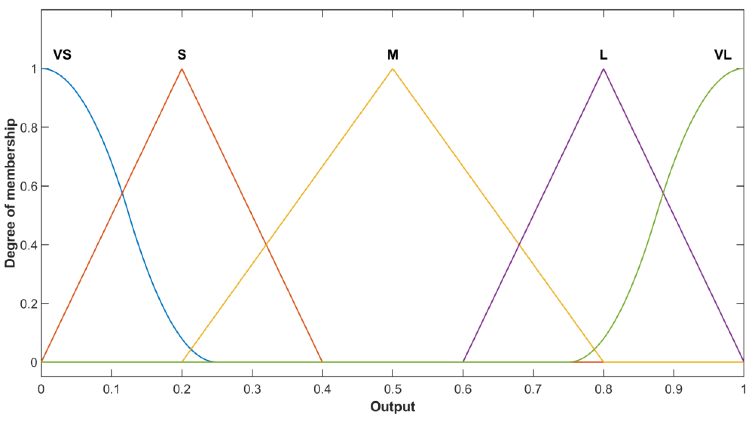
The fuzzy partitions of the input variables are represented by the linguistic variables as follows: NB (negative big), NS (negative small), Z (zero), PS (positive small), and PB (positive big). The output variable is partitioned into five fuzzy sets defined over the normalized domain (0,1): vs. (very small), S (small), M (medium), L (large), and VL (very large). The membership functions are shown in Figure 2 and Figure 3, and the fuzzy inference system is of the Mamdani type. Moreover, the adopted defuzzification method is the centroid method. Figure 4 illustrates the three-dimensional fuzzy rule surface generated from the fuzzy rule base.
The following Lyapunov function is selected:
V = 1 2 s 2 + 1 2 η h ˜ 2 .
Here, h ˜ = h ^ Δ ¯ is the gain estimation error and Δ ¯ sup t Δ is the upper bound of the disturbance.
Taking the derivative of the Lyapunov function (17) and rearranging terms yields
V ˙ = s s ˙ + 1 η h ˜ h ^ ˙ = s k s s h ^ sgn s ρ ^ tanh s ε + Δ + 1 η h ˜ h ^ ˙ = k s s 2 h ^ s ρ ^ s tanh s ε + s Δ + h ˜ s k s s 2 ρ ^ s tanh s ε s h ^ Δ + h ˜ s = k s s 2 ρ ^ s tanh s ε s h ˜ + Δ ¯ Δ + h ˜ s = k s s 2 ρ ^ s tanh s ε s Δ ¯ Δ 0 .
Therefore, it is proved that the system is globally asymptotically stable, and the sliding surface sss reaches s = 0 within a finite time and remains in this state.

3.2. FTDO Design

We integrated a Fixed-Time Disturbance Observer (FTDO) for real-time estimation and compensation of the time-varying total matched uncertainty term to enhance system robustness and reduce chattering. Moreover, chattering problems generally occur because discontinuous functions are employed in the Sliding Mode Disturbance Observer (SMDO). To address both issues, we designed an integral sliding mode (ISM) FTDO based on a nonsingular terminal super-twisting algorithm observation law.
Thus, the total matched uncertainty term is described as
Δ = λ 1 d y + λ 3 f r .
The auxiliary variable is introduced as
z = s μ ,   μ ˙ = Δ ^ .
The ISM manifold is defined by
q = n z ˙ + a z .
where n , a are positive constants.
The estimation of the total matched uncertainty term is obtained through the nonsingular terminal super-twisting algorithm observation law, whose specific form is described as follows:
Δ ^ ˙ = k 1 q α 0 s a t q φ + k 2 q β 0 s a t q φ + w w ˙ = k 3 q α 0 s a t q φ k 4 q β 0 s a t q φ p w ,
where s a t x = x / 1 + x is the continuous saturation function, φ = ϑ q γ , and k i , p , ϑ are all positive constants, with 0 < γ < 1 and 0 < α 0 < 1 < β 0 .
Theorem 1.
If the observer gain parameter k 2 1.2 Δ max and k 3 > k 4 k 2 k 1 , then for the FTDO, the estimation error Δ ˜ and its derivative estimation error Δ ˙ ˜ both converge to zero within a fixed time independent of the initial errors, and the convergence time satisfies.
t T Δ = T q + T w ,
where T q is the fixed time for the sliding surface q to converge to zero, ensuring that the estimation error Δ ˜ of the uncertainty term converges to 0. T w is the fixed time for the estimated velocity w to converge to zero, ensuring that the derivative estimation error Δ ˙ ˜ of the uncertainty term converges to 0. This ensures that both the estimation error and its derivative converge simultaneously, allowing the observer output Δ ^ to be continuous and improving the system’s robustness and anti-interference capability, which facilitates feedforward compensation control.
The observation error vector is defined as follows:
e 1 = q ,   e 2 = w .
The following Lyapunov function is selected:
V 1 = 1 2 e 2 2 + 2 3 k 2 / k 4 e 1 3 2 .
Taking the derivative of the Lyapunov function yields
V ˙ 1 = e 2 e ˙ 2 + k 4 k 2 e 1 1 2 s i g n e 1 e ˙ 1 .
Substituting the error definition (24) and the observation law (22) yields
V ˙ 1 c 1 e 1 α 0 + 1 2 c 2 e 1 β 0 + 1 2 p 2 e 2 2 ,
where c 1 = k 3 k 4 k 2 k 1 and c 2 = k 4 2 .
From the lower bound of the Lyapunov function, it follows that
e 1 2 3 k 2 2 k 4 V 1 ,   e 1 k 2 2 k 4 2 3 V 1 2 3 .
Substituting (28) into (27) yields
V ˙ 1 a 1 V 1 θ a 2 V 1 ξ ,
where a 1 = c 1 2 k 4 k 2 2 α 0 + 1 3 and a 2 = c 2 2 k 4 k 2 2 β 0 + 1 3 . According to Polyakov’s lemma, the ISM manifold and the observer law variables q and w both converge to zero within a fixed time, and the fixed time is given by
t T Δ = 1 a 1 1 θ + 1 a 2 ξ 1 ,
where q and w both converge to zero; and given that z ˙ = Δ ˜ with q = n Δ ˜ + a z , we obtain Δ ˜ = a n z . In this case, the eigenvalue of the first-order linear system is a n < 0 , indicating stability; therefore, the estimation error Δ ˜ of the uncertainty term also converges to zero within a fixed time. In general, prior knowledge of the derivative of the uncertainty term is unavailable, and this derivative typically changes more slowly compared to the dynamic variation of the observer. Hence, we can assume that Δ ˙ = 0 . Moreover, according to the observer law, when q and w converge to zero, the derivative estimation error Δ ^ ˙ of the uncertainty term also converges to zero within a fixed time. Therefore, the estimation error of the uncertainty term Δ ˙ ˜ = Δ ˙ Δ ^ ˙ converges to zero within a fixed time, and both the estimation error Δ ˜ and its derivative Δ ˙ ˜ converge to zero within a fixed time.

3.3. Stability Analysis of the Closed-Loop System

The following Lyapunov function is selected:
V 2 = 1 2 s 2 + 1 2 η h ˜ 2 + 1 2 Δ ˜ 2 + 1 2 q 2 + 1 2 w 2 .
V = 1 2 s 2 + 1 2 η h ˜ 2 It is already proved that the previous part is stable. Here, the proof proceeds with
s s ˙ + 1 η h ˜ h ˜ ˙ k s s 2 ρ ^ s tanh s ε s Δ ¯ Δ .
Thus, the Lyapunov function becomes
V Δ = 1 2 Δ ˜ 2 + 1 2 q 2 + 1 2 w 2 .
Taking the derivative of the Lyapunov function yields
V ˙ Δ = Δ ˜ Δ ˜ ˙ + q q ˙ + w w ˙ = Δ ˜ k 1 | q | α 0 σ q + k 2 | q | β 0 σ q + w + q ( q ˙ w ) k 3 w | q | α 0 σ q k 4 w | q | β 0 σ q p w 2 .
Applying Young’s inequality results in
| Δ ˜ | | q | α 0 ε 1 2 Δ ˜ 2 + k 1 2 2 ε 1 | q | 2 α 0 , | Δ ˜ | | q | β 0 ε 1 2 Δ ˜ 2 + k 2 2 2 ε 1 | q | 2 β 0 , | Δ ˜ w | ε 2 2 Δ ˜ 2 + 1 2 ε 2 w 2 , | q w | 1 2 q 2 + 1 2 w 2 . ,
where ε 1 , ε 2 0 , 1 .
Substituting (35) into (34) yields
V ˙ Δ 1 2 Δ ˜ 2 γ 1 | q | α 0 + 1 γ 2 | q | β 0 + 1 p 1 + ε 2 2 w 2 ,
where γ 1 = k 1 k 3 k 1 2 ε 1 > 0 , and γ 2 = k 2 k 4 k 2 2 ε 1 > 0 .
In summary, it can be concluded that
V ˙ 2 k s s 2 ρ ^ | s | tanh | s | ε | s | Δ ¯ Δ 1 2 Δ ˜ 2 γ 1 | q | α 0 + 1 γ 2 | q | β 0 + 1 p 1 + ε 2 2 w 2 < 0 ,
where p > 1 + ε 2 2 , and that the closed-loop system is globally asymptotically stable.
Therefore, the final rudder-angle control law is described as
δ = 1 B k s s h ^ s i g n s ρ ^ tanh s ε A Δ ^ .
The overall structure of the control system is shown in Figure 5. The “AF-SMC” block represents the controller; the “Saturation” block denotes the rudder actuator; the “FTDO” block is the fixed-time disturbance observer, which estimates the total matched uncertainty term and provides feedforward compensation; and the “Yaw Dynamics” block represents the yaw dynamics modeled by the MMG equations.

4. Simulation Results

We conducted simulations to verify the effectiveness of the proposed algorithm. The simulation model was constructed using the 3-DOF nonlinear MMG model, and it was parameterized using the real-ship data of the very large underactuated vessel “Tianjin”, with specific parameters shown in Table 2. The wind, wave, and current disturbances acting on the ship were consistent with those described in [9]. Three controllers were compared in the simulations. To ensure a fair comparison, a unified tuning strategy was adopted: nominal parameters were first determined from the Nomoto model in Section 2 according to target dynamic indices, and then slightly adjusted in the MMG-based simulation under actuator saturation and rate constraints to balance tracking accuracy, chattering suppression, and disturbance rejection. The controller parameters were set as follows:
λ 1 = 0.1 , λ 2 = 1 , λ 3 = 3 , k s = 0.6 , ε = 0.2 , η = 0.16 , n = 1 , a = 0.6 , γ = 0.7 , p = 0.6 , ϑ = 0.5 , α 0 = 0.5 , β 0 = 1.5 , k 1 = 1.8 , k 2 = 0.6 , k 3 = 0.4 , k 4 = 0.1 .
The simulations adopted four reference waypoints, with the reference path generated by connecting these waypoints. The specific reference waypoints were WP1(0, 0), WP2(1500, 500), WP3(3000, 2000), and WP4(6000, 2000). The initial state of the ship was set as x 0 , y 0 , ψ 0 , u 0 , v 0 , r 0 = [ 600   m , 500   m , 30   d e g , 6   m / s , 0   m / s , 0   m / s ] . For comparative analysis, the sliding mode controller (SMC) was employed as the classical benchmark in the simulations. The results show that the AF-SMC, building on the SMC, effectively reduces tracking errors through gain adaptation, while the AF-SMC+FTDO further enhances disturbance rejection, thus achieving the best overall control performance among the compared methods. Figure 6 shows the ship tracking the predefined path, including local zoomed-in views. Figure 7 depicts the cross-track position errors during the tracking process. All three controllers can effectively suppress the cross-track position error most of the time. In particular, the AF-SMC+FTDO controller shows significantly suppressed error at turning points compared with the other methods. Larger cross-track errors occur sporadically, mainly because of larger heading correction amplitudes when the ship passes through waypoints or sharp turns, increasing transient deviations.
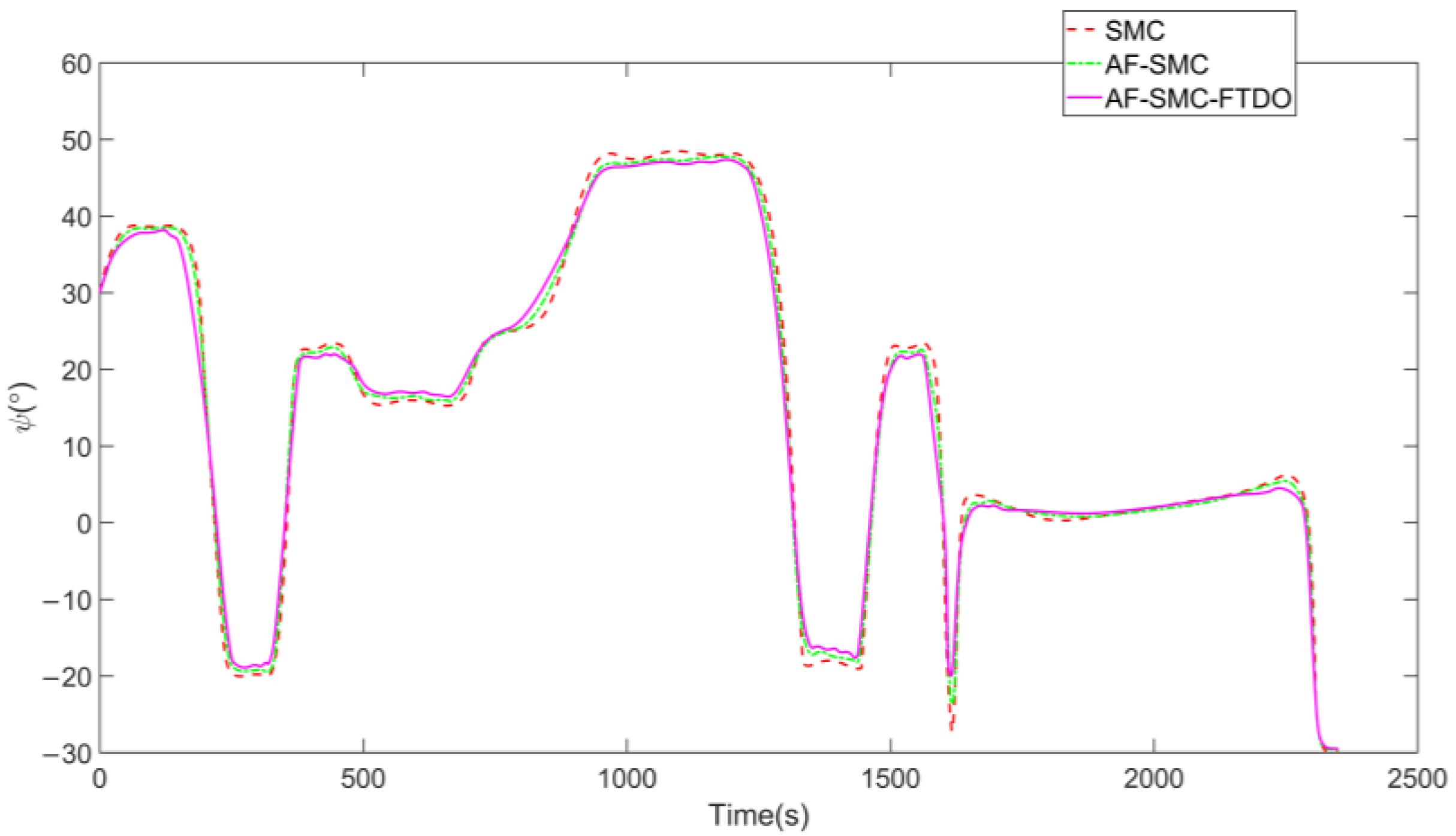
Figure 8 and Figure 9 show the time histories of the ship’s heading angle and rudder angle. The heading angle fluctuates between −30° and 50°, whereas the rudder angle ranges from −35° to 35°, consistent with navigational practice. The rudder angle variation produced by the proposed algorithm is the smoothest, with only a slight jitter during turning. This aligns with actual navigation characteristics and indicates that the designed controller possesses good stability and control accuracy. Figure 10 illustrates the variations of the ship’s velocities in the u , v , and r directions. The surge velocity u remains relatively stable throughout the path-tracking process, the sway velocity v exhibits only transient fluctuations during turns or waypoint passages, and the yaw rate r generates significant peaks at path bends, reflecting the dynamic characteristics of ship attitude adjustment.
Figure 11 shows the variations of the adaptive gain and fuzzy gain. Under the AF-SMC controller, the adaptive gain exhibits a continuous increase and tends to saturate at a high level. After introducing the FTDO, a considerable reduction in the gain growth rate and its overall magnitude is observed. This indicates that the FTDO can effectively compensate for external disturbances and model uncertainties, reducing the controller’s reliance on high gain and thereby alleviating the workload of actuators, such as the rudder. Fuzzy gain variations indicate that both controllers can dynamically adjust the control effort according to the system error—by temporarily increasing when the error is large or the attitude adjustment is drastic and rapidly decreasing once the error converges. The introduction of the FTDO yields slightly reduced peak fuzzy gain and smoother fluctuations, further highlighting the positive effect of disturbance observation and compensation on improving control smoothness. Figure 12 presents the observation results of the FTDO for the system’s total uncertainty term (including external disturbances and modeling errors). The observer can rapidly converge to the vicinity of the true uncertainty value within a finite time and achieve stable tracking. The observation error remains consistently small throughout the process, fully verifying the fast convergence and high-accuracy observation capabilities of the proposed FTDO, which can provide reliable uncertainty estimation support for ship path tracking under complex sea conditions.

5. Conclusions

We proposed a control scheme that integrates an FTDO with AF-SMC to address system uncertainties and external disturbances in ship path tracking. The proposed controller employs the FTDO to achieve rapid estimation of the total uncertainty term without requiring persistent excitation and adjusts the sliding-mode gain online through an adaptive mechanism and fuzzy logic system, thereby enhancing adaptability and robustness. Simulation results showed that the proposed strategy ensures rapid convergence of path tracking errors while maintaining smooth rudder angle inputs under control input saturation constraints. Compared with traditional SMC and AF-SMC methods, the proposed controller demonstrates enhanced robustness, reduced steady-state error, and superior rudder-angle response performance under wind and wave disturbances. Furthermore, the controller possesses a fixed-time convergence property, where the system convergence time is independent of the initial error, thereby improving the predictability of the response. Overall, the simulations validate the effectiveness and practicality of the proposed method for ship path tracking control in complex environments with various disturbances. We will conduct full-scale or hardware-in-the-loop experiments to assess its control performance under real sea conditions and test its stability and robustness under more complex disturbance modeling conditions.

Author Contributions

Conceptualization, Y.L. and C.B.; methodology, Y.L.; software, Y.L.; validation, Y.L. and R.G.; formal analysis, Y.L.; investigation, Y.L. and R.G.; resources, Y.L.; data curation, Y.L.; writing—original draft preparation, Y.L.; writing—review and editing, Y.L. and C.B.; supervision, C.B.; project administration, C.B.; funding acquisition, C.B. All authors have read and agreed to the published version of the manuscript.

Funding

The APC was funded by the Inner Mongolia Key Laboratory of New Energy and Energy Storage Technology Inner Mongolia University of Technology.

Data Availability Statement

Data are contained within the article.

Conflicts of Interest

The authors declare no conflicts of interest.

Abbreviations

The following abbreviations are used in this manuscript:
AF-SMCAdaptive fuzzy sliding-mode control
FTDOFixed-time disturbance observer
ISMIntegral sliding mode
LLarge
MMedium
NBNegative big
NSNegative small
PBPositive big
PSPositive small
SSmall
VLVery large
VSVery small
ZZero

References

  1. Wu, J.; Peng, H.; Ohtsu, K.; Kitagawa, G.; Itoh, T. Ship’s tracking control based on nonlinear time series model. Appl. Ocean Res. 2012, 36, 1–11. [Google Scholar] [CrossRef]
  2. Li, Z.; Bu, R. Trajectory tracking of under-actuated ships based on optimal sliding mode control with state observer. Ocean Eng. 2021, 233, 109186. [Google Scholar] [CrossRef]
  3. Liu, H.; Sun, N.; Ren, G. Finite-time fast nonsingular terminal sliding mode path-following control for underactuated marine surface vehicles with input saturation. Ocean Eng. 2022, 262, 112327. [Google Scholar] [CrossRef]
  4. Li, R.; Jia, B.; Fan, S.; Pan, X. A novel active disturbance rejection control with hyperbolic tangent function for path following of underactuated marine surface ships. Meas. Control 2020, 53, 1579–1588. [Google Scholar] [CrossRef]
  5. Li, Z.; Li, R.; Bu, R. Path following of under-actuated ships based on model predictive control with state observer. J. Mar. Sci. Technol. 2021, 26, 408–418. [Google Scholar] [CrossRef]
  6. Zhang, H.; Zhang, X.; Bu, R. Sliding mode adaptive control for ship path following with sideslip angle observer. Ocean Eng. 2022, 251, 111106. [Google Scholar] [CrossRef]
  7. Zhang, H.; Zhang, X.; Cao, T.; Bu, R. Active disturbance rejection control for ship path following with Euler method. Ocean Eng. 2022, 247, 110516. [Google Scholar] [CrossRef]
  8. Yue, J.; Liu, L.; Peng, Z.; Wang, D.; Li, T. Data-driven adaptive extended state observer design for autonomous surface vehicles with unknown input gains based on concurrent learning. Neurocomputing 2022, 467, 337–347. [Google Scholar] [CrossRef]
  9. Zhang, G.; Liu, S.; Huang, J.; Zhang, W. Dynamic Event-Triggered Path-Following Control of Underactuated Surface Vehicle With the Experiment Verification. IEEE Trans. Veh. Technol. 2022, 71, 10415–10425. [Google Scholar] [CrossRef]
  10. Lakhekar, G.V.; Waghmare, L.M. Robust self-organising fuzzy sliding mode-based path-following control for autonomous underwater vehicles. J. Mar. Eng. Technol. 2023, 22, 131–152. [Google Scholar] [CrossRef]
  11. Su, Y.; Wan, L.; Zhang, D.; Huang, F. An improved adaptive integral line-of-sight guidance law for unmanned surface vehicles with uncertainties. Appl. Ocean Res. 2021, 108, 102488. [Google Scholar] [CrossRef]
  12. Wan, L.; Su, Y.; Zhang, H.; Shi, B.; AbouOmar, M.S. An improved integral light-of-sight guidance law for path following of unmanned surface vehicles. Ocean Eng. 2020, 205, 107302. [Google Scholar] [CrossRef]
  13. Wang, Y.; Tong, H.; Wang, C. High-Gain Observer-Based Line-of-Sight Guidance for Adaptive Neural Path Following Control of Underactuated Marine Surface Vessels. IEEE Access 2019, 7, 26088–26101. [Google Scholar] [CrossRef]
  14. Xiao, C.; Zhong, L.; Jianqiang, Z.; Dechao, Z.; Jiao, D. Adaptive sliding-mode path following control system of the underactuated USV under the influence of ocean currents. J. Syst. Eng. Electron. 2018, 29, 1271–1283. [Google Scholar] [CrossRef]
  15. Yan, Y.; Yu, S.; Sun, C. Event-triggered sliding mode tracking control of autonomous surface vehicles. J. Franklin Inst. 2021, 358, 4393–4409. [Google Scholar] [CrossRef]
  16. Zhang, H.; Zhang, X.; Gao, S.; Han, X.; Ma, D. Global fast terminal sliding mode control for path following of ultra large underactuated ship based on predictive LOS guidance. Ocean Eng. 2023, 285, 115387. [Google Scholar] [CrossRef]
  17. Yan, Y.; Zhao, X.; Yu, S.; Wang, C. Barrier function-based adaptive neural network sliding mode control of autonomous surface vehicles. Ocean Eng. 2021, 238, 109684. [Google Scholar] [CrossRef]
  18. Zhang, G.; Zhang, C.; Li, J.; Zhang, X. Improved composite learning path-following control for the underactuated cable-laying ship via the double layers logical guidance. Ocean Eng. 2020, 207, 107342. [Google Scholar] [CrossRef]
  19. Zhang, G.; Li, J.; Jin, X.; Liu, C. Robust Adaptive Neural Control for Wing-Sail-Assisted Vehicle via the Multiport Event-Triggered Approach. IEEE Trans. Cybern. 2022, 52, 12916–12928. [Google Scholar] [CrossRef] [PubMed]
  20. Weng, Y.; Wang, N.; Guedes Soares, C. Data-driven sideslip observer-based adaptive sliding-mode path-following control of underactuated marine vessels. Ocean Eng. 2020, 197, 106910. [Google Scholar] [CrossRef]
  21. Zhang, H.; Zhang, X.; Bu, R. Radial Basis Function Neural Network Sliding Mode Control for Ship Path Following Based on Position Prediction. J. Mar. Sci. Eng. 2021, 9, 1055. [Google Scholar] [CrossRef]
  22. Zhao, J.; Cai, C.; Liu, Y. Barrier Lyapunov Function-based adaptive prescribed-time extended state observers design for unmanned surface vehicles subject to unknown disturbances. Ocean Eng. 2023, 270, 113671. [Google Scholar] [CrossRef]
Figure 1. Geodetic coordinate system and relative coordinate system.
Jmse 13 01788 g001
Figure 2. Input membership functions.
Jmse 13 01788 g002
Figure 3. Output membership functions.
Jmse 13 01788 g003
Figure 4. Fuzzy rule surface of ρ ^ . The color represents the normalized output value, where blue indicates low values and red indicates high values.
Jmse 13 01788 g004
Figure 5. Control system block diagram.
Jmse 13 01788 g005
Figure 6. XY-plane trajectory of ship path tracking.
Jmse 13 01788 g006
Figure 7. Comparison of cross-track errors.
Jmse 13 01788 g007
Figure 8. Comparison of heading angle variations.
Jmse 13 01788 g008
Figure 9. Comparison of rudder angle variations.
Jmse 13 01788 g009
Figure 10. Variations of u , v , and r for the three controllers.
Jmse 13 01788 g010
Figure 11. Adaptive gain h ^ and fuzzy gain ρ ^ .
Jmse 13 01788 g011
Figure 12. Observation results of the FTDO.
Jmse 13 01788 g012
Table 1. Fuzzy rules.
e y e ψ
NBNSZPSPB
NBVLVLLLM
NSVLLMSS
ZLMVSML
PSSSMLVL
PBMLLVLVL
Table 2. Ship parameters.
Ship ParametersValueUnit
Full-load draft20.5m
Full-load displacement396,167t
Ship length L361.9m
Ship beam B65m
Block coefficient0.8323
Frontal windage area2962.1m2
Lateral windage area1031.94m2
Propeller diameter14.3m
Propeller pitch11.375m
Rudder area68.8m2
Rudder aspect ratio5.375\
Designed propeller rotational speed50n/min
Turning lag index T1142\
Turning ability index K0.09\
Disclaimer/Publisher’s Note: The statements, opinions and data contained in all publications are solely those of the individual author(s) and contributor(s) and not of MDPI and/or the editor(s). MDPI and/or the editor(s) disclaim responsibility for any injury to people or property resulting from any ideas, methods, instructions or products referred to in the content.