Article

The Float-Over Installation with a Dynamic Positioning Vessel Using Improved Fuzzy Control: An Experimental Study

1
School of Ocean and Civil Engineering, Shanghai Jiao Tong University, Shanghai 200240, China
2
State Key Laboratory of Ocean Engineering, Shanghai Jiao Tong University, Shanghai 200240, China
3
Beijing Institute of Astronautical Systems Engineering, Beijing 100076, China
*
Author to whom correspondence should be addressed.
J. Mar. Sci. Eng. 2025, 13(9), 1782; https://doi.org/10.3390/jmse13091782
Submission received: 12 July 2025 / Revised: 25 August 2025 / Accepted: 28 August 2025 / Published: 16 September 2025
(This article belongs to the Section Ocean Engineering)

Abstract

To improve the maneuverability of the installation vessel and shorten the operational timeframe, a dynamic positioning (DP) semi-submersible vessel with a sophisticated control strategy is utilized to replace the conventional traction systems and towing tugs. In this paper, an improved fuzzy control law is developed for the standby and docking stage of the float-over installation. The control thrust is divided into a dynamic part and a static part. Both parts are computed based on a set of logical if–then-type statements based on the human sense of realism and expert experience. The dynamic part acts as the proportional–derivative control, while the static part contributes the integral action. The implementation of accumulation time enhances the static thrust’s effectiveness in positioning the vessel compared to traditional integral control methods. A model test is further conducted to validate the effectiveness of the proposed improved fuzzy control based on a DP barge. Wind, wave, and current are considered from different directions in the experiment to simulate the practical operation condition. Experimental results illustrate that the proposed improved fuzzy control law can accurately keep position and guide the vessel into the slot of the jacket. Finally, some conclusions are summarized for the characteristic of fender forces in different environmental load directions.

1. Introduction

The lifting method and float-over method are the two most commonly used for installing topsides of offshore platforms in the recent decades. The selection of installation technique relies on water depth, topside weight, environmental conditions, and numerous additional factors. The float-over technique is favored when the topside weight surpasses the lifting capabilities of the accessible heavy lift crane [1]. A float-over installation barge facilitates the transport of the topside into position. Subsequently, the topside is transferred onto the jacket using the Leg Mating Unit (LMU), Deck Support Unit (DSU), and fender systems.
The conventional float-over installation is operated by towing tugs and auxiliary lines. By the cooperation of towing tugs, mooring cables and mating lines, the barge is steered into the slot for mating and load transfer [2]. Most research emphasizes this approach, particularly the nonlinear dynamics of vessel motions and the intricate interactions among the barge, topside structure, and impact-absorbing system.
Xu et al. [3,4] investigated the complex multi-body hydrodynamics of two or three moored barges by experimental and numerical tools, revealing that the hydrodynamic interactions are much more complicated than a single barge. Dessi et al. [5] used rigid and elastic models to analyze the connection between the barges and the topside. The design considerations of LMU are well discussed in Yuan et al. [6] and Choi et al. [7]. A fully coupled time-domain model was established by Chen et al. [8], which captured the nonlinear dynamics of barge motions, impact-absorbing system and mooring systems. The simulation results agreed well with the commercial computational software. Bai et al. [9] presented the experimental analysis of an innovative installation method with the rapid transfer technique, and found that the trim angles synchronize with the topside before the second jack-down operation. For the twin-barge float-over system, Bai et al. [10] conducted experimental researches on two identical barges elastically hinged with the topside in heading, beaming and quartering waves. Results illustrated that the shielding effect had a great influence on the amplitude and phase-difference of the barge motions. More state-of-the-art progress of numerical modeling, model test and in-site measurement of float-over systems is summarized in Fang et al. [11] and Qin et al. [12].
The dynamic positioning (DP) float-over installation is another float-over approach by using a semi-submersible vessel (see Figure 1). Several DP float-over installation projects have been performed in the last decades, such as Majan Increment Project and Huizhou 25-8 Project. However, the related theoretical studies are limited, particularly concerning the design of the DP controller. Bakar [13] presented the float-over methodology for the topsides using portable DP2 vessel and the technical challenges for offshore operation. A Deck Transportation Vessel (DTV) was upgraded with DP2 capability by adding two portable azimuth thrusters. Yi et al. [14] simulated the DP float-over installation with considerations of the sway and surge fenders. He et al. [15] established a time-domain simulation program to analyze the motion of DP vessel as well as the fender forces. The simulation results agree well with the model test. Wang et al. [16] investigated the dynamic responses of a twin-barge float-over system integrating flexible connections and DP system. Both numerical simulations and model tests were conducted to analyze the character of the coupled system.
For the DP float-over installation, an advanced control strategy must be designed to ensure the vessel is entering the slot and keeping the impact with fenders within an acceptable limit. The position-keeping problem in float-over installation has been extensively studied by researchers. In addition to traditional proportional–integral–derivative control (PID), model reference adaptive systems, self-tuning regulators, gain scheduling, machine learning methods, real-time parameter estimation, and many other control techniques are adopted to control the vessel motion [17]. However, most of the control methods require accurate model parameters, which is hard to obtain in practical applications. To deal with the model uncertainty and unknown disturbances, fuzzy logic control is adopted. Yamamoto and Morooka [18] designed a fuzzy controller for the DP system of a semi-submersible platform, but only sway motion was considered in their simulation. Tzung-Hang Lee and Lin [19] presented a fuzzy logic controller which takes the vessel heading, yaw rate, position errors and velocity as inputs, and generated the rudder angles, propeller thrust and later bow thrust through fuzzy inference. However, these methods may not perform well in a real complex environment. The control action is just calculated according to the position and velocity feedback, and its relationship with the external excitation is unclear. In this paper, we consider the external loads acting on the vessel, which can be categorized into two parts: dynamic part and static part. The dynamic part is time-varying but has a zero average value. The static part varies very slowly with time and has the same direction as the wind, wave, and current.
Based on the above consideration, this study presents a novel human-inspired fuzzy controller for float-over installations in marine operations. The control system integrates vessel dynamics through position, heading, and velocity measurements to generate control forces. These forces split into dynamic and static components based on human-like logical reasoning. The dynamic component functions as a proportional–derivative (PD) controller, while the static part implements an enhanced integral control with temporal accumulation. The accumulation nature of the static force fundamentally solves the phenomenon of integral saturation and is more flexible than traditional integral control. We validate the controller’s performance through model tests on a DP barge under multi-directional environmental loads. The paper structure flows from experimental setup through numerical modeling and controller design to results and conclusions. This research advances marine control systems by mimicking human decision-making patterns in vessel positioning tasks.

2. Experimental Set-Up

The model-scale experimental investigation is performed at Ocean Engineering Basin, Shanghai Jiao Tong University. The scaling ratio is selected as 1:40 according to the physical capability of the basin, and the Froude scaling law is adopted in the experiment. The model tests examine all the float-over installation phases, with focus on standby and docking operations. The basin measures 50.0 m in length, 30.0 m in width, with 6 m maximum depth capacity. The facility features a variable-depth bottom system (0–6 m range) and can simulate multiple environmental conditions. Motion tracking utilizes an advanced non-contact optical system to record 6-Degree of Freedom (DOF) vessel responses under combined wind–wave–current environmental loads. The 3-DoF sensors monitor fender forces throughout the tests.

2.1. Super X-Class Model

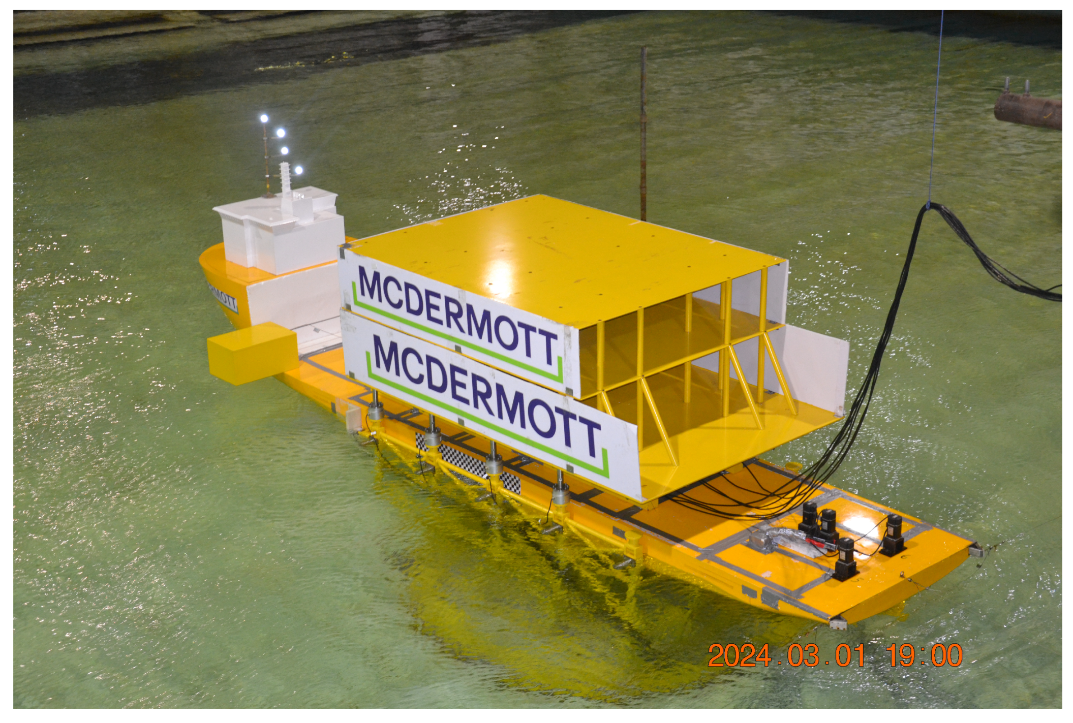
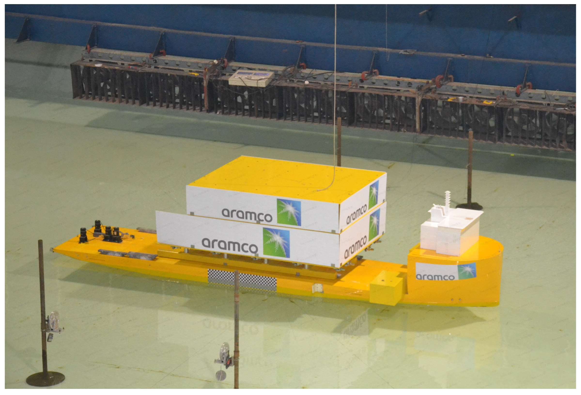
The experimental model of the semi-submersible super X-class vessel replicates key features of the prototype, including major dimensions, hull geometry, mass distribution, and inertial characteristics. The model also maintains accurate displacement values and draft measurements. The model meets ±3% of the specified prototype values for mass and moment inertia. The hull dimensions, center of gravity, and displacement are within ±1%. Major parameters of the barge are listed in Table 1, and the photo of the vessel model is shown in Figure 2.
The experimental super X-Class vessel model comprises a wooden core structure with glass-fiber-reinforced plastic (GFRP) coating for waterproofing. The hull design incorporates dedicated compartments for ballast placement, enabling precise adjustment of vessel mass properties, including weight distribution, gravitational center, and rotational inertia parameters. The internal architecture accommodates propulsion components, specifically servo motors and drive systems for thruster operation. Enhanced structural reinforcement is implemented in the deck assembly to mitigate deformation risks from topside loading conditions. Notable features include lateral square panels affixed to the topside structure, specifically designed to simulate wind exposure area characteristics.
The model-scale jacket structure, fabricated from steel, adheres to precise project specifications. This model replicates actual water depth conditions without truncation, maintaining authentic height proportions. The jacket base is securely anchored to the tank floor to eliminate oscillations during docking and undocking operations. The topside consists of an integrated deck that is to be installed on top of the jacket. The topside component exhibits high visual fidelity while maintaining critical physical parameters—mass distribution, structural rigidity, gravitational center, and wind exposure area.

2.2. LMU, DSU and Fender Model

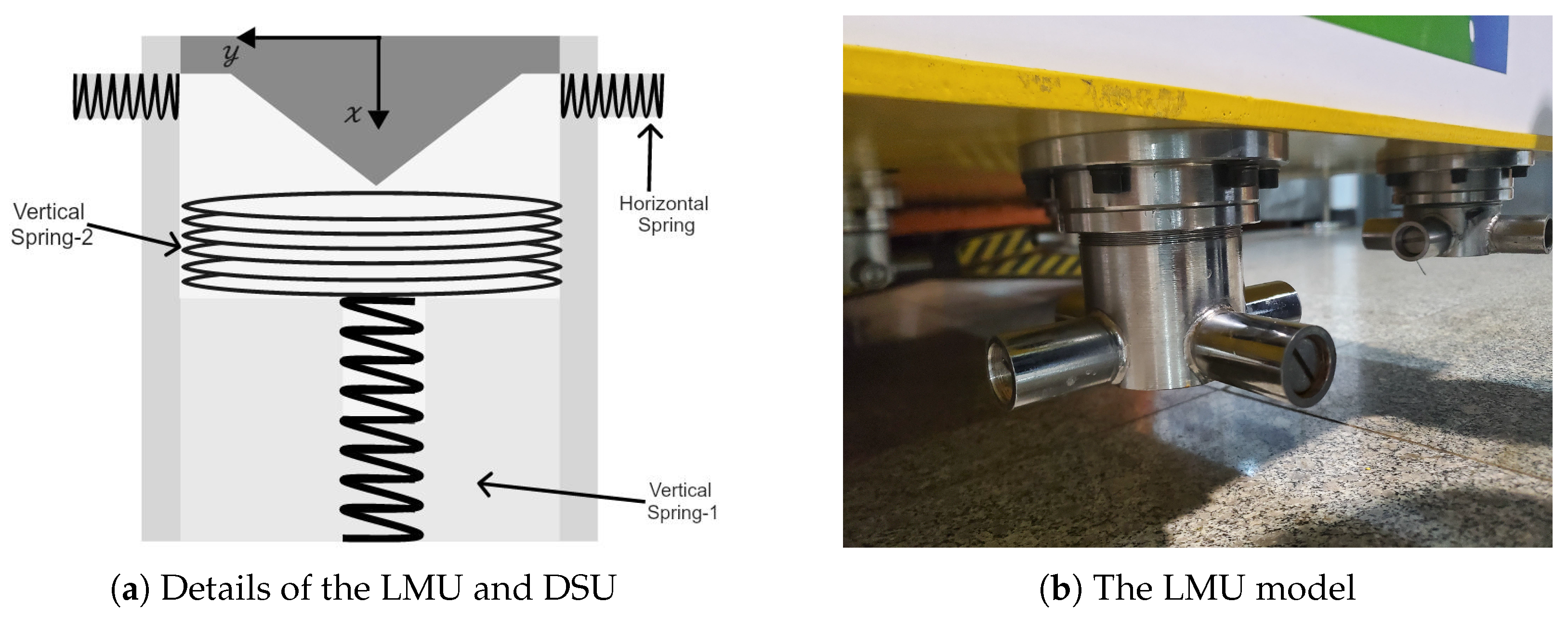
The LMUs are positioned on the main legs of the jacket and barge support structure. Each jacket leg features a stabbing cone at its apex. The LMU system incorporates receiver cones, which are mounted beneath vertical elastomeric shock absorbers. This configuration prevents direct steel-to-steel contact during the mating phase, thus protecting the structural integrity of both topside and jacket components.
To model the horizontal and vertical stiffness, the LMU is designed as shown in Figure 3 with a local coordinate system. The DSU is installed on the deck to stabilize the topside. It functions as a shock absorber, reducing impact loads between the topside and the vessel. It restricts both vertical and horizontal movements of the topside during float-over installation. The DSU mounted on the vessel has similar components to the LMU, while the horizontal elastomer of DSUs fixed on the vessel is replaced with the friction material in the receptor cone.
Sway fenders are positioned on each jacket leg to limit the sway motions of the vessel and reduce impact loads on the jacket legs during the mating operation. They are numbered from A1–A4 on one side and B1–B4 on the other side. A nominal gap of 2.5 mm in model scale between the vessel side shell and sway fenders is maintained. Surge fenders are installed on the jacket legs in order to attain perfect pre-mating position prior. By putting a series of known weights on the fender model, the corresponding pressure is measured through a resistive sensor. The stiffness of the mechanical springs matches the required performance characteristics of the sway (reaction force = 500 MT, deflection = 300 mm) and surge fenders (reaction force = 150 MT, deflection = 400 mm). The experimental configuration of LMU, DSU, and fenders is depicted in Figure 4.

2.3. Thruster Model

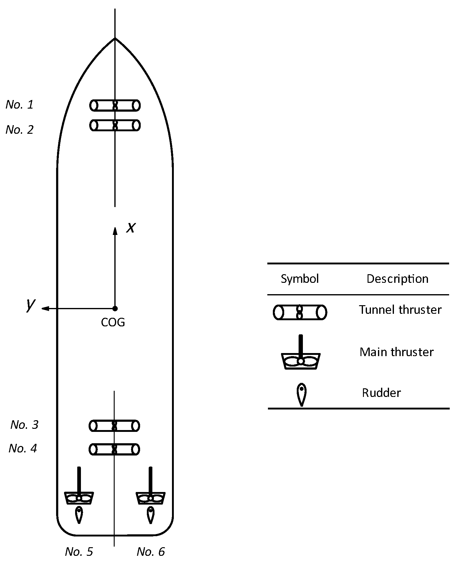
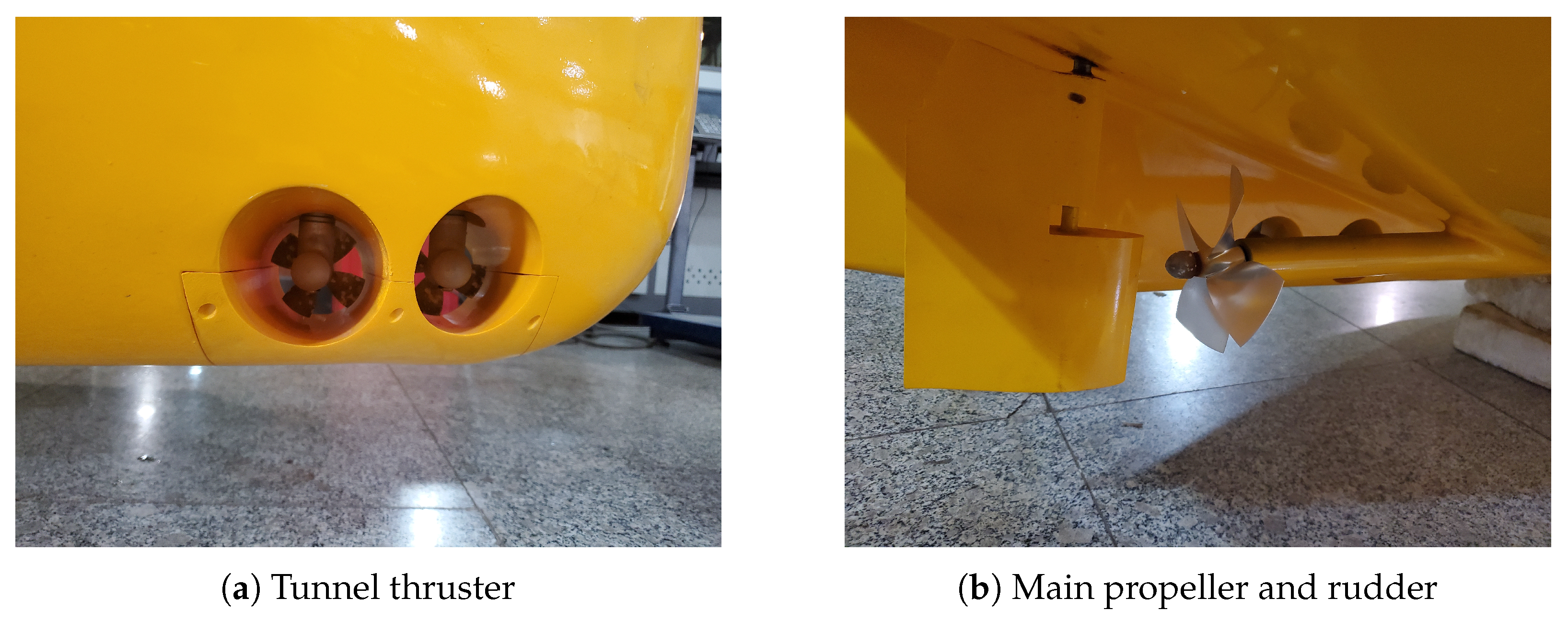
The super X-class vessel model is equipped with four tunnel thrusters (76 mm in diameter) and two main propellers (120 mm in diameter) with rudders. The Ka-470 series propellers are applied in experiments. The thrust configuration is illustrated in Figure 5 and the physical thruster models can be seen in Figure 6. The location and maximum thrust are detailed in Table 2. These thrusters are controlled by the proposed improved fuzzy controller with the real-time motion data provided by a motion-tracking system. The Alpha–Beta filter is used to reconstruct the low-frequency motions from the measured data, as it only needs to adjust a few parameters and does not need the accurate system parameter. The controller then gives the control thrust based on position and velocity errors based on the thrust allocation algorithm [20]. An onboard controller receives the feedback thrust commands from an onshore system and distributes this over the thrusters. Each servo motor drives each propeller individually [21]. This model-scale DP system emulates the operational characteristics of an authentic DP mechanism, thereby producing verisimilar positioning behavior and control responses.

3. The Design of the Improved Fuzzy DP Control System

3.1. Modeling of Dynamic Positioning

There are two coordinate systems used in docking tests: the global frame ( O g - X g Y g Z g ), and the body-fixed frame ( X Y Z ) as shown in Figure 7. The global frame is earth-fixed, and the origin O g coincides with the CoG (Center of Gravity) of the vessel when the vessel is fully docked. The body-fixed frame is fixed to the vessel and thus moves along with it. Usually, the position and orientation are measured in the global frame, and the velocity and loads acting on the vessel are expressed in the body-fixed frame.
In the design of DP controller, only the motions in the horizontal plane are considered. The relationship between the earth-fixed position η and its body-fixed velocity ν is given by
η ˙ = R ( ψ ) ν
R ( ψ ) = cos ψ sin ψ 0 sin ψ cos ψ 0 0 0 1
where η = [ x , y , z ] T denotes the surge, sway, and yaw angle in the global frame, and ν = [ u , v , r ] T denotes the corresponding velocities. The nonlinear equations governing the three degrees of freedom in low-frequency motion can be expressed as follows:
M ν ˙ + C R B ( ν ) ν + C A ν r ν r + D ν r + G ( η ) = τ e n v + τ + τ f
where M is the vessel inertial matrix including added mass, and C R B ( ν ) and C A ν r are the skew-symmetric Coriolis and centripetal matrices of the rigid body and the added mass. D ν r is the damping vector which is a function of the relative velocity vector ν r between the vessel and current. For DP and low-speed maneuverings, linear and nonlinear damping is a feasible approximation, which may be referred to in Fotuhi et al. [22]. G ( η ) is the generalized restoring vector caused by buoyancy and gravitation. τ is the actual control force produced by thrusters. τ e n v is the external environmental loads, and τ f is the impact force caused by the fender system. During the standby and docking phase, the vessel-topside system can be considered an integrated unit, and therefore, the LMU and DSU loads are excluded from this analysis.
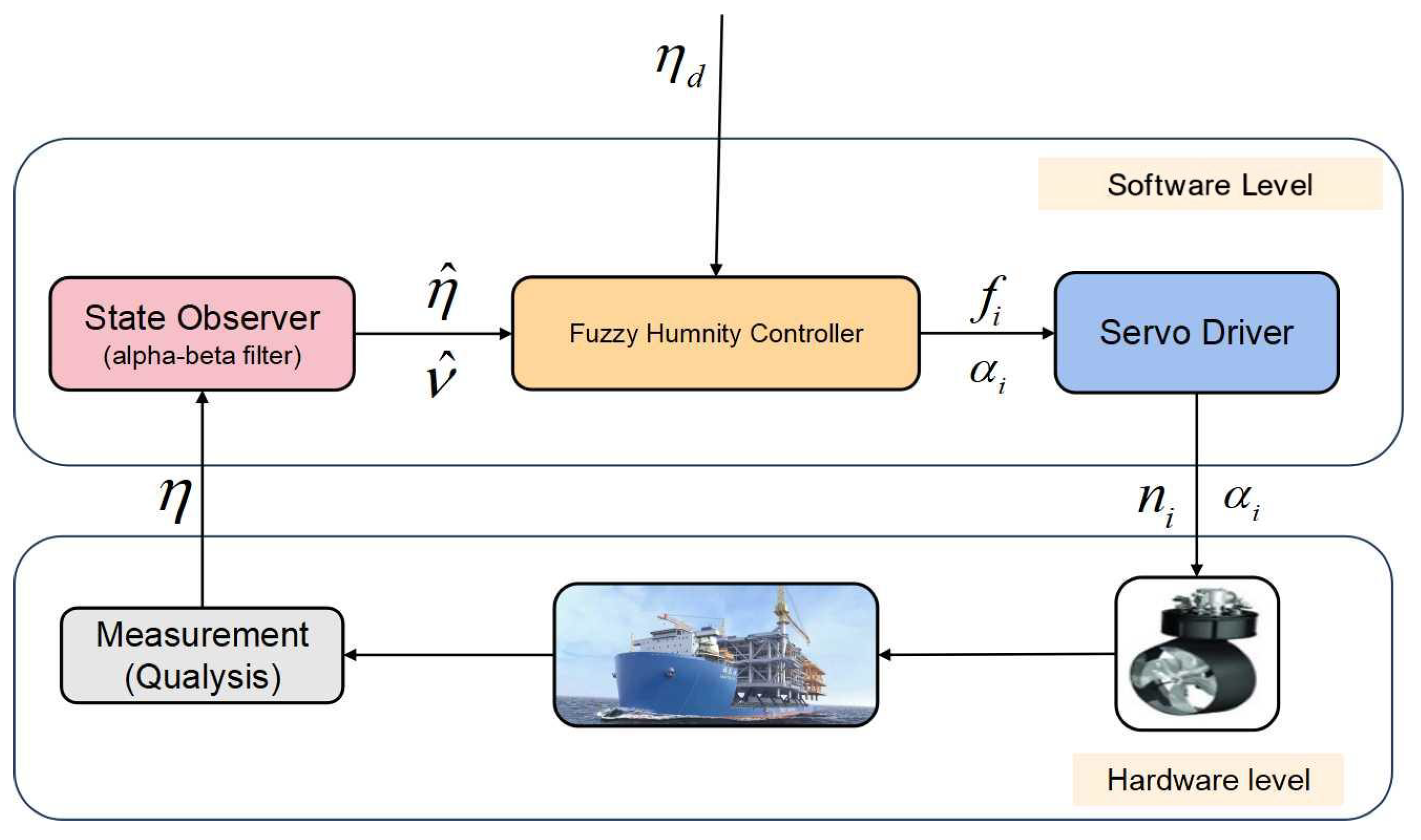
In this experimental investigation, a sophisticated non-contact optical motion-tracking system (Qualysis in the present study) is employed to record vessel kinematics under combined environmental loads, including aerodynamic forces, hydrodynamic wave interactions, and current-induced effects. The implementation of a Alpha–Beta filtering algorithm facilitates the extraction and reconstruction of low-frequency motion components from the acquired measurement data. The primary research objective encompasses the formulation of an optimal control force τ expression to ensure precise position maintenance and successful jacket docking. Figure 8 illustrates the structure diagram of the proposed controller system. Here, the controller includes the fuzzy controller and the thruster allocation algorithm.

3.2. Improved Fuzzy Controller Design

The conventional control systems employ mathematical models based on algebraic or differential equations to regulate processes. In contrast, fuzzy control systems can incorporate human-derived heuristics, experiential knowledge, and intuitive reasoning through logical rule sets. For the purpose of demonstrating this concept, we simplify our analysis by assuming the barge maintains a position at the origin, where positional and velocity absolute values correspond directly to their respective error measurements. The methodology presented herein can be generalized for broader operational parameters and conditions.

3.2.1. Dynamic Component

The dynamic component of the controller deals with the position keeping problem around the expected position. The fuzzy logic controller first receives the low-frequency motion η p and velocity ν expressed in the body-fixed frame, where η p can be calculated by η p = R ( 1 ) ( ψ ) η . Then each of the six numerical inputs is assigned to linguistically described fuzzy sets defined over certain ranges.
We use seven fuzzy sets for position input η p : negative big (NB), negative middle (NM), negative small (NS), zero (ZO), positive small (PS), positive middle (PM), and positive big (PB). Eight fuzzy sets are designed for the velocity input ν : negative big (NB), negative middle (NM), negative small (NS), negative zero (NZ), positive zero (PZ), positive small (PS), positive middle (PM), and positive big (PB). These fuzzy sets are defined in the ranges listed in Table 3 and Table 4.
It should be noticed that before the input is assigned to a fuzzy set, it needs to first be multiplied by a so-called position sensitivity factor K e or a velocity sensitivity factor K e c . These factors define to what extent the position error or velocity error is considered big or small. For instance, if we choose K e = 0.00833 0.00833 0.0833 T , then when the surge and sway error exceed 1 m and yaw angle error exceeds 10 deg, they shall be assigned as big.
The output of the fuzzy controller is the required force provided by thrusters to keep the vessel position. It is discretely defined in 11 linguistic values as shown in Table 5. Here NL denotes negative large and PL positive large. Similarly, the output τ d y n shall be multiplied by the mass matrix of the vessel and another gain factor K u to obtain the final dynamic control force.
The fuzzy logic control system establishes mappings between aggregated fuzzy input sets and their corresponding fuzzy output sets through a knowledge-based rule framework, which comprises conditional if–then statements that are formulated by leveraging domain expertise and empirical understanding of the system behavior.
According to the fuzzy sets, a total of 56 linguistic rules have been set up as detailed in Table 6. The governing principles are derived from empirical observations of standard oscillatory behavior around the equilibrium state, demonstrating clear physical meaning in their manifestation.
If both η p and ν are negative big, the vessel has a strong tendency to move in the negative direction, so a positive large force is needed to resist this deviation. If η p is negative small or near zero, and ν is negative big, which means the barge is slightly ahead of the desired position and tends to move in the negative direction with a large velocity, then a positive middle force is desirable to resist this trend in advance. If η p is positive middle or positive big, and ν is negative big, the vessel is far ahead of the desired position but moves towards it. In this situation, no control force is needed and the output is zero. Each rule in Table 6 can be explained in this way. The computational methodology of present fuzzy controller bears similarities to conventional PD controllers, while offering enhanced adaptability and rational control mechanisms. This controller demonstrates superior efficiency by preemptively generating restoring forces and implementing velocity damping with minimal control intervention.

3.2.2. Static Component

In the absence of the static component of the fuzzy controller, there is a possibility that the barge may be situated at a location that deviates from the anticipated point. The static component of the controller addresses the issue of guiding the barge back to the desired position, effectively functioning as the integral control mechanism.
In the computation of the static component of the fuzzy controller, three inputs are required: the average position over the preceding control intervals η p m e a n (in this study, set to 10), the velocity from the most recent control interval ν p r e , and the velocity at the present moment ν . The duration for calculating the average position can be modified to influence the responsiveness of the static force to positional variations. Initially, the static force is zero but progressively accumulates throughout the entire control process. During each control interval,
τ s t a t i c = τ s t a t i c + i n c r e m e n t
This increment can be calculated based on the following fuzzy logic Table 7, Table 8 and Table 9. It should be noticed that the values in Table 7 only apply for surge and sway, and the yaw has another set of values due to the unit difference.
If η p m e a n is NL and ν p r e < ν , a compensatory force of considerable positive magnitude must be applied to counteract this displacement and maintain positional stability. The increment may vary from PL to PZ based on the distance between the vessel and the expected position. However, when η p m e a n is NL and ν p r e > ν , the vessel tends to return to the expected position. In this context, observation of the vessel motion is recommended without implementing additional control forces. The inherent accumulative characteristics of the present controller enable the static force to respond rapidly to motion variations observed over preceding temporal intervals. Meanwhile, because the static force takes both the velocity at this control interval and the most recent control interval, which indicates the movement trend of the barge, it can have a shorter response time and perform better under sudden disturbances.
Through the integration of dynamic and static force components, the proposed fuzzy logic control system demonstrates adaptive behavior analogous to human decision-making processes. The fuzzy controller can be finally expressed as follows:
τ = K s t a t i c τ s t a t i c + K d y n τ d y n
Here, the controller gains K s t a t i c and K d y n are used to adjust the relative relationship according to the real-time position. Both are originally set to one. If the barge oscillates violently near the equilibrium position, we can increase K d y n to strengthen the dynamic control. If the barge maintains balance at a distance from the setpoint, then we can increase K s t a t i c to strengthen the static control. We tune both controller gains until the barge balances at our desired setpoint. This control schematic can be applied to different ocean engineering applications where the floating structure needs to be positioned or move in a desired direction. The complete workflow of the fuzzy controller is depicted in Figure 9.

4. Results and Discussion

In order to validate the efficacy of the proposed improved fuzzy controller, a series of model tests are conducted using this controller for the standby and docking of super X-class vessel. The sampling frequency of the measured data is set to 50 Hz, while the control frequency is 2 Hz to avoid wear and tear of the thrusters. The results are analyzed by taking the statistics from the time histories and presented in prototype scale.
Stern heading (0 deg), stern quartering (45 deg) and beam (90 deg) seas are simulated in the physical model-scale experiments. The wind, wave, and current are applied in the same direction. A JONSWAP spectrum is used to generate the irregular waves. The environmental conditions used in the model test are based on the measured data at the practical installation site and presented in Table 10. Before the standby and docking test, single wind and single current tests are conducted to calibrate the speed and measure the environmental loads acting on the vessel for the parameter adjustment of the proposed fuzzy controller. All data in the model test are measured through resistive sensors installed on the barge.

4.1. Standby Tests

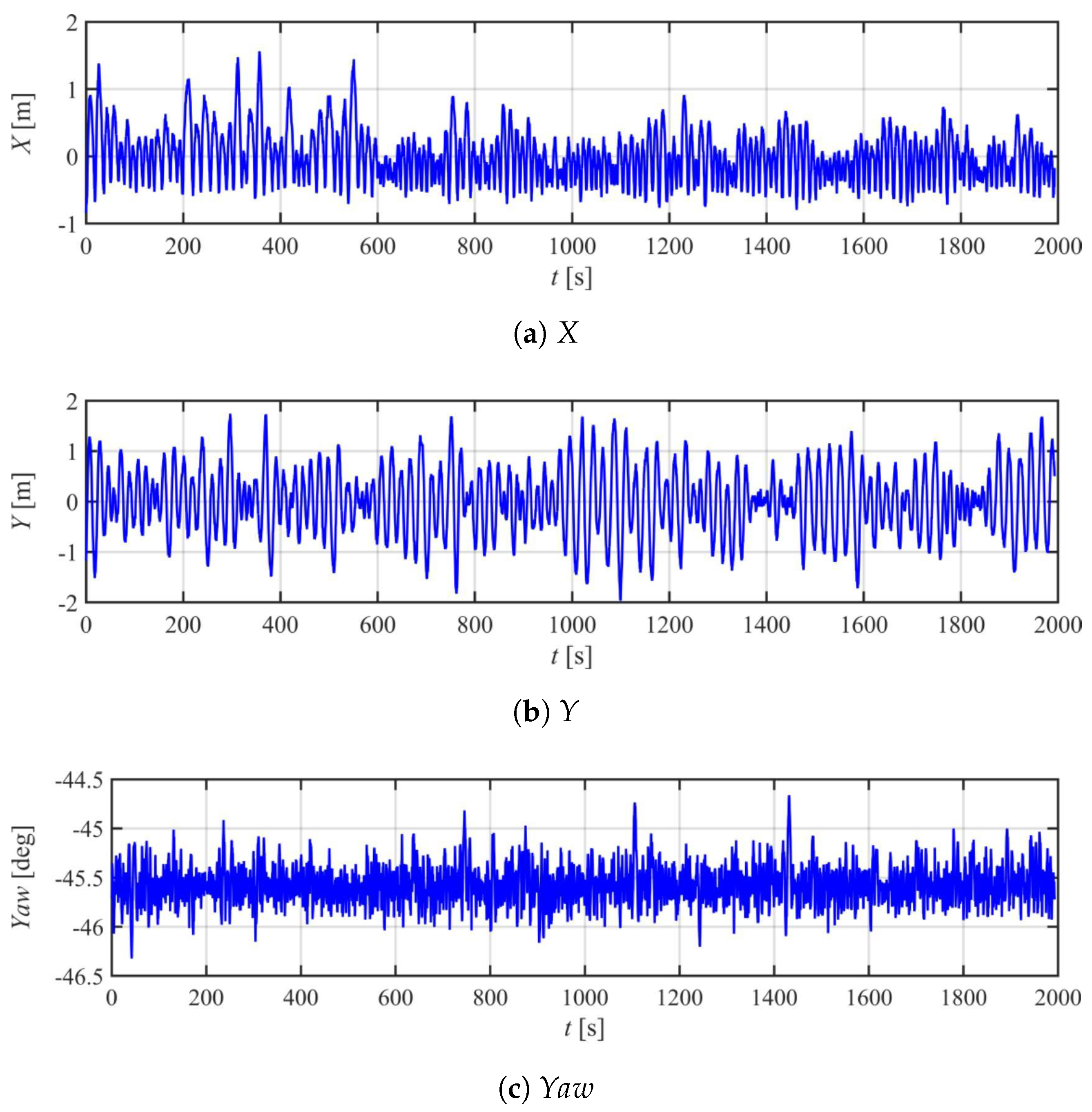
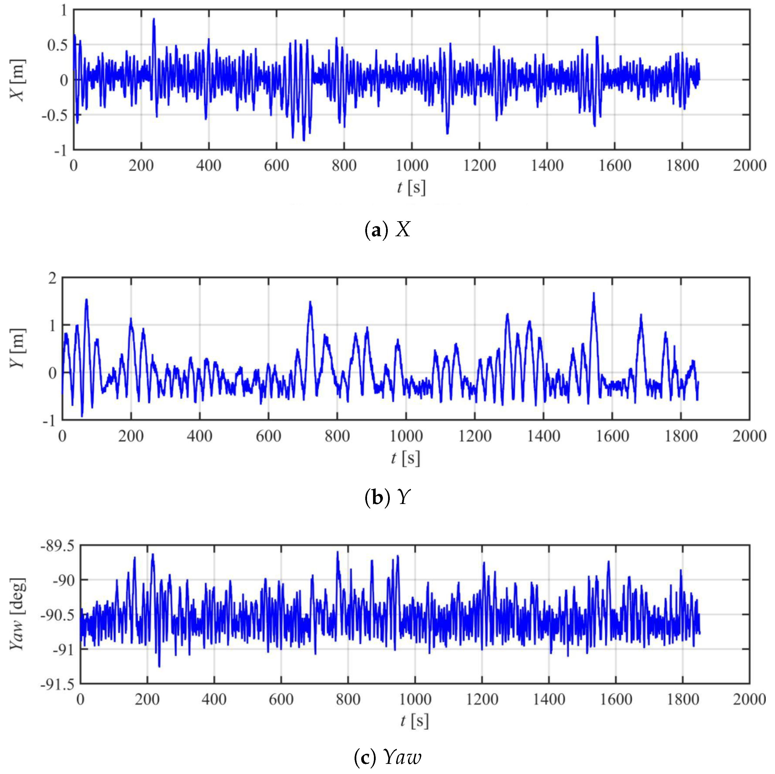
Standby in the float-over installation means the station-keeping situation for the waiting operation window. In physical experiments, the vessel model equipped with the DP control system is dynamically positioned at a specified point under the influence of wind, wave, and current. The positioning accuracy, particularly regarding the headings, is of importance in assessing whether the vessel can successfully dock into the slot without any risk of collision. The snapshots of the standby tests are given in Figure 10, and corresponding motions in one case are presented in Figure 11, Figure 12 and Figure 13. The motion statistics are summarized in Table 11.
It can be seen that the vessel is well stabilized around the equilibrium position. For the positioning accuracy in the X direction, it is basically within the range of [−2 m, 2 m] for the case of 0 deg. This reduces to [−1 m, 1 m] for the cases of 45 deg and 90 deg. Because the environmental loads always come from X direction, only the two main propellers can help to keep the vessel position. The radius of the propeller is relatively large (120 mm) and must be continuously switched between forward and reverse rotation around the equilibrium, so it is very hard to achieve a better positioning accuracy. For the case of 45 deg and 90 deg, the four tunnel thrusters will work to achieve a more stable control in X direction.
It is indicated that there is a small constant error of about 0.5 deg around the expected heading direction. The variation range of the yaw angle is basically kept in [−0.5 deg, 0.5 deg] for all the three cases. In fact, considering the scale ratio of 1:40, 2 m in the graph corresponds to 5 cm in model-scale. This positioning accuracy is very high for a nearly 6 m vessel model exposed to environmental loads.
The standby stage provides a very important circumstance for the improved fuzzy fuzzy controller to adjust the parameters, such as the absolute value in Table 5 and Table 7, as well as the dynamic controller gain K d y n and static controller gain K s t a t i c . According to the positioning situation of the vessel, we carefully tune all the control parameters to achieve a reasonable combination, which will be used in the following docking stage.

4.2. Docking Test

DP docking experiments are also conducted to evaluate and validate the performance characteristics of the proposed fuzzy control system in maintaining vessel position and heading during docking operations. The vessel is controlled by changing the setpoints manually in order to move forward step by step according to the current positioning accuracy. Special attention needs to be paid when the vessel first enters the slot. The lateral displacement must be maintained within prescribed tolerances prior to transitioning to subsequent reference points, as excessive deviation could result in transverse large collisions between the vessel and the sway fender system. Figure 14 shows a snapshot of the DP docking test in wave.
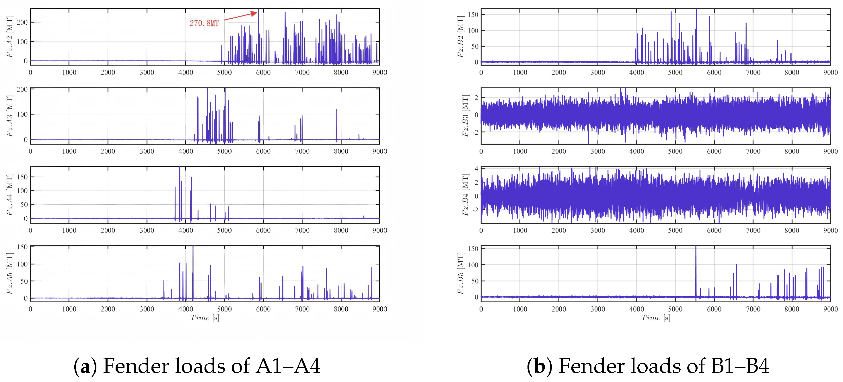
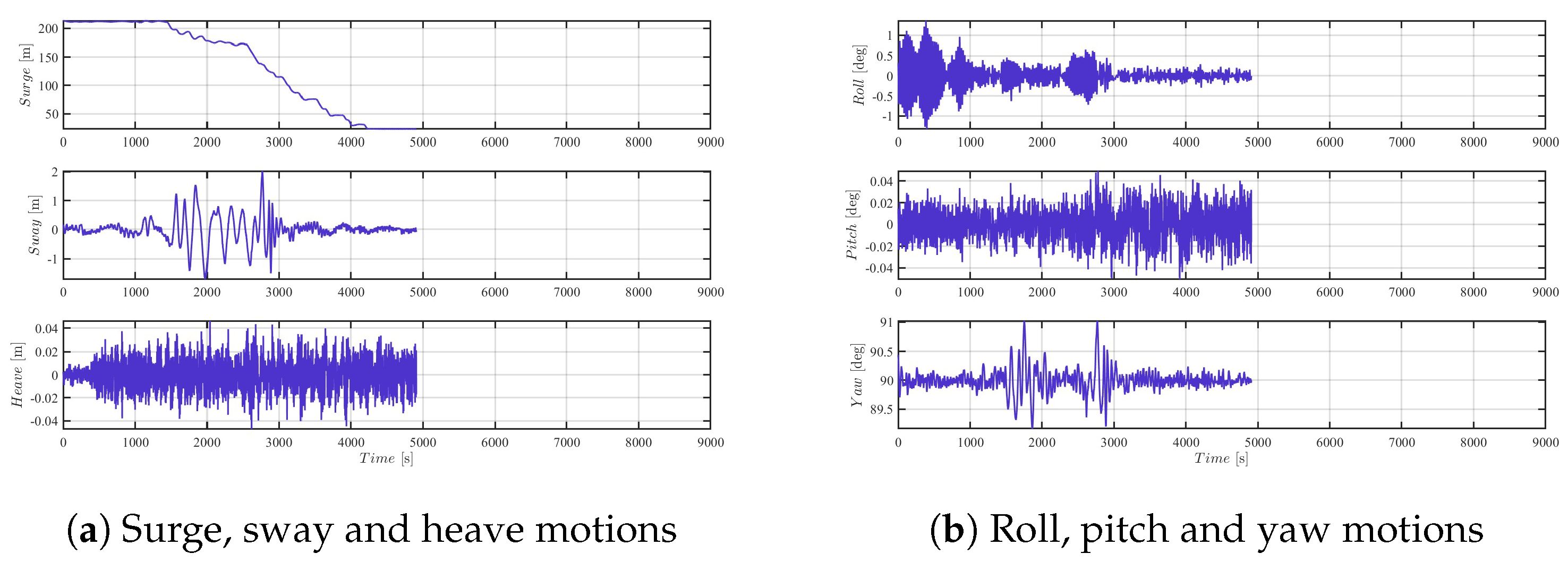
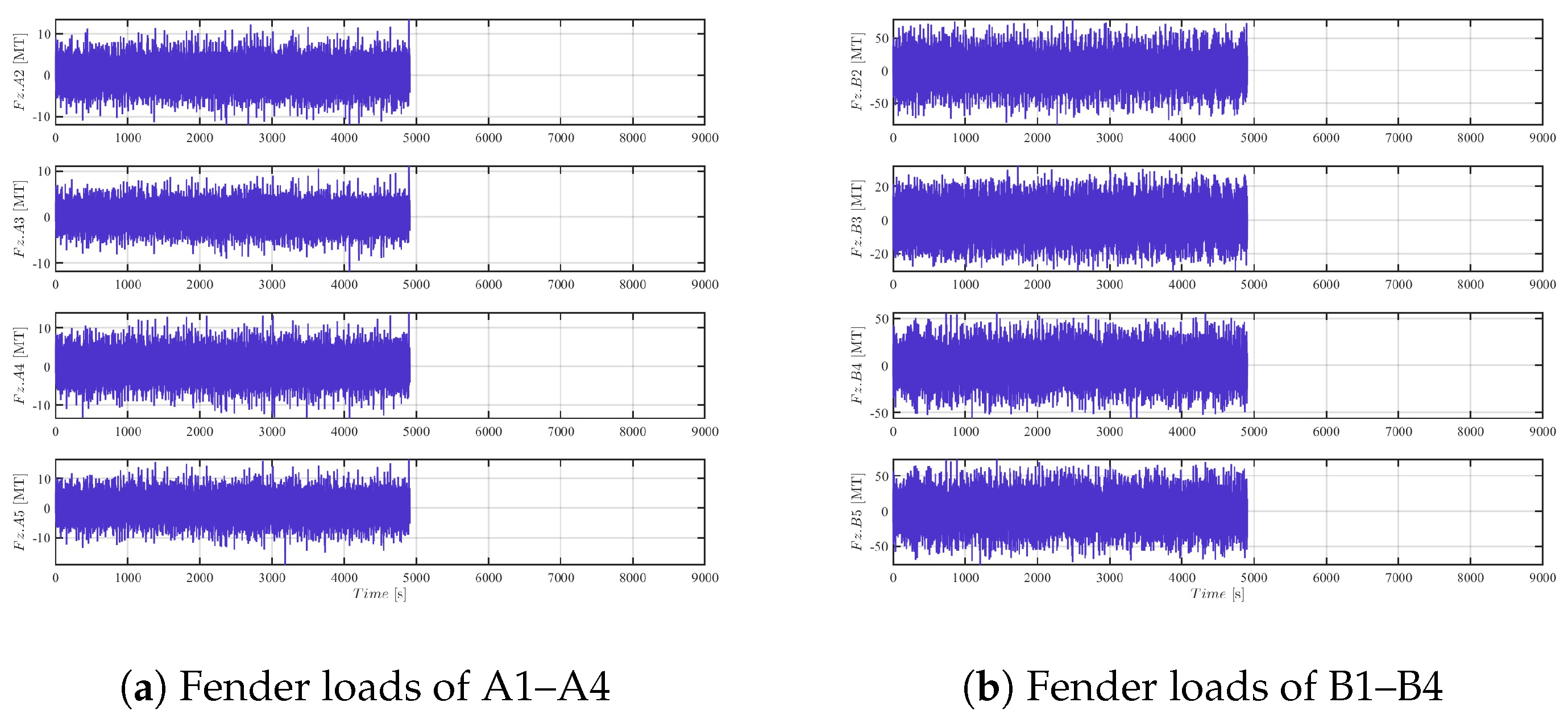
Figure 15 presents the motions of the barge in the 0 deg docking test, and the corresponding sway fender forces are shown in Figure 16. For sway fenders, the reaction loads in the local Z axis are dominant, so the X-axis component is thus not presented here.
It can be seen that the DP vessel model enters the slot at about 3000 s. Both the motions and fender forces demonstrate strong oscillation characteristics once the vessel enters. Restricted by the sway fenders, the barge is no longer completely controlled by the DP system. Continuous collision with the sway fender changes the barge acceleration immediately and causes the high-frequency oscillations as shown in the figures.
The amplitude of fender force varies greatly ranging from a few tons to hundreds of tons. The maximum reaction load is 270.8 tons, which is much larger than the results of 45 deg and 90 deg as shown later. Considering that the environmental loads come from the surge direction, the sway loads acting on the ship shall be small theoretically. This phenomenon is unexpected, as the environmental loads are primarily aligned with the surge direction, and the sway loads should theoretically be minimal. However, the observed high sway fender forces may be attributed to complex hydrodynamic interactions such as wave diffraction around the jacket structure, thruster hysteresis during rapid directional changes, and coupling effects between sway and roll motions. These effects are known to introduce lateral loads not accounted for in simplified models and have been discussed in prior studies [15,17]. Further investigation is warranted to quantify these dynamics and improve predictive accuracy.
First, the environmental condition for the 0 deg heading is much harsher than for the other two wave headings. The environmental loads in the sway direction are also introduced by the jacket and might be larger than expected.
Second, four tunnel thrusters are used to control the heading and sway motion of the barge. As no static force is required in 0 deg, and the sway and yaw angle vary in the vicinity of zero, the tunnel thrusters must continuously change from forward to reverse rotation rapidly to provide the required force. However, due to the inherent hysteresis of the thrusters, forward and reverse rotation will cause insufficient thrust in a short time, then a large sway or yaw angle will be induced and increase the collision with fenders. This shortcoming is determined by the thruster configuration of the barge and incorporating additional azimuth thrusters may address this issue.
Third, the coupling effect between sway and roll motions. As the tunnel thrusters are installed below the center of gravity of the barge, an additional roll moment is induced when controlling the sway and yaw motions. The gap between the vessel side shell and sway fenders is only 2.5 mm in the model test; this roll motion will absolutely cause the collision of the vessel shell with fenders. However, this coupling effect exists for all the DP vessels, especially those with a small water-plane area. Adding the roll motion into the feedback control loop may help to reduce this coupling effect.
The experimental results with respect to 45 deg and 90 deg are presented in Figure 17, Figure 18, Figure 19 and Figure 20. Except several extreme values, most of the sway fender forces are relatively small. The maximum reaction loads are 213.67 tons and 51.22 tons, respectively. Considering all the experimental results, 90 deg is the best angle to conduct a docking operation with the best positioning accuracy and minimal reaction force, which may be attributed by the relatively small environmental conditions. This is also determined by the thruster configuration of the barge. In the 90 deg docking test, the controller must provide a static force to resist the mean environmental loads, and so all the four tunnel thrusters are always rotating in forward direction. The difference of the rotation speed can provide the rest sway force and yaw moment so that the generated thruster force is very stable. In general, the docking tests are very successful, and performance of the proposed improved fuzzy controller is satisfactory.

5. Conclusions

In this paper, an improved fuzzy control law based on the fuzzy system is developed for the standby and docking stage of the float-over installation. The controller utilizes the measured vessel position, heading, and velocity to produce the control force, which is subsequently divided into dynamic and static components. Both components are calculated based on a series of logical if–then statements informed by human intuition and experience. The dynamic component functions as proportional–derivative control, while the static component provides integral action. The design methodology of the controller is thoroughly detailed. Additionally, a model test is conducted to validate the efficacy of the proposed improved fuzzy control strategy applied to a dynamically positioned barge. The experimental setup accounts for wind, wave, and current at angles of 0 deg, 45 deg, and 90 deg to replicate realistic operational conditions.
The experimental findings indicate that the proposed improved fuzzy control law effectively maintains position and directs the vessel into the jacket slot. The positioning accuracy in X direction is basically within the range of [−2 m, 2 m] for the case of 0 deg, and it reduces to [−1 m, 1 m] for the case of 45 deg and 90 deg. Given that only the four tunnel thrusters are capable of generating transverse forces, particular attention must be paid to docking at 0 degrees. The tunnel thrusters must rapidly alternate between forward and reverse rotations to generate the necessary force, leading to significant reaction forces on the sway fender. Future research will concentrate on incorporating the additional roll moment induced by the thrusters into the controller design. This adjustment aims to mitigate the sway-yaw-roll coupling effect and reduce the risk of collisions with fenders. Additionally, the current control action is essentially discrete, and thus more work should be performed to transform it to continuous by using membership functions. A realistic numerical simulation platform also needs to be established to consider more different cases and may help facilitate future field testing.

Author Contributions

Methodology, Y.W. and L.W.; Validation, Y.W.; Investigation, R.G. and L.W.; Resources, R.G.; Data curation, Y.W.; Writing—original draft, Y.W.; Writing—review & editing, R.G. and L.W.; Supervision, X.W.; Project administration, X.W. All authors have read and agreed to the published version of the manuscript.

Funding

This research was funded by National Key Research and Development Program of China (Grant No. 2023YFC2809801), Opening Foundation of State Key Laboratory of Maritime Technology and Safety (Grant No. W24CG000040), and Floatover Model Test Project from Majan Project Package 01.

Data Availability Statement

Data will be made available on request.

Conflicts of Interest

The authors declare that they have no known competing financial interests or personal relationships that could have appeared to influence the work reported in this paper.

References

  1. Jung, J.J.; Lee, W.S.; Shin, H.S.; Kim, Y.H. Evaluating the impact load on the offshore platform during float-over topside installation. In Proceedings of the International Ocean and Polar Engineering Conference, Osaka, Japan, 21–26 July 2009; p. 09-330. [Google Scholar]
  2. Bai, X.; Li, D.; Fan, M.; Yi, C. Research and application of floatover pperations using dynamically positioned vessels in South China Sea. In Proceedings of the International Ocean and Polar Engineering Conference, Busan, Republic of Korea, 15–20 June 2014; p. 14-411. [Google Scholar]
  3. Xu, X.; Li, X.; Yang, J.M.; Xiao, L.F. Hydrodynamic interactions of three barges in close proximity in a floatover installation. China Ocean Eng. 2016, 30, 343–358. [Google Scholar] [CrossRef]
  4. Xu, X.; Yang, J.M.; Li, X.; Xu, Y.L. Time-domain simulation for coupled motions of three barges moored side-by-side in floatover operation. China Ocean Eng. 2015, 29, 155–168. [Google Scholar] [CrossRef]
  5. Dessi, D.; Faiella, E.; Pigna, C.; Celli, C.; Miliante, T.; Paolo, E.D. Experimental analysis of the seakeeping response of a double-barge float-over system for topside transportation. Int. J. Offshore Polar Eng. 2019, 29, 198–206. [Google Scholar] [CrossRef]
  6. Yuan, R.H.; Wang, A.M.; Li, H.L.; Qin, L.C.; Xu, J.K.; Min, H. Design considerations of leg mating units for floatover installations. In Proceedings of the International Ocean and Polar Engineering Conference, Rhodes, Greece, 17–22 June 2012; p. 12-128. [Google Scholar]
  7. Choi, Y.M.; Nam, B.W.; Hong, S.Y. Numerical modeling of load transfer unit of the float-over installation. In Proceedings of the International Ocean and Polar Engineering Conference, Busan, Republic of Korea, 15–20 June 2014; Volume All Days, p. 14-016. [Google Scholar]
  8. Chen, M.; Zou, M.; Zhu, L.; Ouyang, M.; Liang, Q.; Zhao, W. A fully coupled time domain model capturing nonlinear dynamics of float-over deck installation. Ocean Eng. 2024, 293, 116721. [Google Scholar] [CrossRef]
  9. Bai, X.; Luo, H.; Xie, P. Experimental analysis of dynamic response of floatover installation using rapid transfer technique in continuous load transfer process. J. Mar. Sci. Technol. 2020, 25, 1182–1198. [Google Scholar] [CrossRef]
  10. Bai, X.; Luo, H.; Xie, P. Experimental analysis of hydrodynamic response of the twin-barge floatover installation for mega topsides. Ocean Eng. 2021, 219, 108302. [Google Scholar] [CrossRef]
  11. Fang, X.; Guo, X.; Tian, X.; Wang, P.; Lu, W.; Li, X. A review on the numerical and experimental modeling of the floatover installations. Ocean Eng. 2023, 272, 113774. [Google Scholar] [CrossRef]
  12. Qin, L.; Bai, X.; Luo, H.; Li, H.; Ding, H. Review on recent research and technical challenges of floatover installation operation. Ocean Eng. 2022, 253, 111378. [Google Scholar] [CrossRef]
  13. Bakar, A.A. Innovative Float-over Installation Approach via Portable DP Vessel. In Proceedings of the International Ocean and Polar Engineering Conference, Rhodes, Greece, 20–25 June 2021; p. 21-1108. [Google Scholar]
  14. Yi, F.; Liu, T.; Wang, L. Numerical Simulation of Float-Over Installation Under the Influence of Fender with Dynamically Positioned Vessel. In Proceedings of the International Ocean and Polar Engineering Conference, Sapporo, Japan, 10–15 June 2018; p. 18-082. [Google Scholar]
  15. He, H.; Wang, L.; Zhu, Y.; Xu, S. Numerical and experimental study on the docking of a dynamically positioned barge in float-over installation. Ships Offshore Struct. 2021, 16, 505–515. [Google Scholar] [CrossRef]
  16. Wang, R.; Shi, Q.; Tian, X.; Guo, X.; Li, X.; Yang, J. Dynamic responses of a twin-DP-barge float-over installation system with flexible connections. J. Ocean Eng. Sci. 2024, 10, 353–365. [Google Scholar] [CrossRef]
  17. Sørensen, A.J. A survey of dynamic positioning control systems. Annu. Rev. Control 2011, 35, 123–136. [Google Scholar] [CrossRef]
  18. Yamamoto, M.; Morooka, C. Dynamic positioning system of semi-submersible platform using fuzzy control. J. Braz. Soc. Mech. Sci. Eng. 2005, 27, 449–455. [Google Scholar] [CrossRef]
  19. Tzung-Hang Lee, Y.C.; Lin, Y.M. Dynamic positioning of drilling vessels with a fuzzy logic controller. Int. J. Syst. Sci. 2002, 33, 979–993. [Google Scholar] [CrossRef]
  20. Popov, I.; Koschorrek, P.; Haghani, A.; Jeinsch, T. Adaptive Kalman Filtering for Dynamic Positioning of Marine Vessels. IFAC-PapersOnLine 2017, 50, 1121–1126. [Google Scholar] [CrossRef]
  21. Johansen, T.; Fossen, T.; Berge, S. Constrained nonlinear control allocation with singularity avoidance using sequential quadratic programming. IEEE Trans. Control Syst. Technol. 2004, 12, 211–216. [Google Scholar] [CrossRef]
  22. Fotuhi, M.J.; Hazem, Z.B.; Bingül, Z. Comparison of Joint Friction Estimation Models for Laboratory 2 DOF Double Dual Twin Rotor Aero-dynamical System. In Proceedings of the IECON 2018—44th Annual Conference of the IEEE Industrial Electronics Society, Washington, DC, USA, 21–23 October 2018; pp. 2231–2236. [Google Scholar]
Figure 1. The float-over installation operation using DP semi-submersible vessel [12].
Jmse 13 01782 g001
Figure 2. The DP semi-submersible vessel model in physical experiments.
Jmse 13 01782 g002
Figure 3. The design of the LMU and DSU models.
Jmse 13 01782 g003
Figure 4. The configuration of the LMU, DSU, and fenders in model test.
Jmse 13 01782 g004
Figure 5. The configuration of thrusters.
Jmse 13 01782 g005
Figure 6. The thruster and rudder models.
Jmse 13 01782 g006
Figure 7. The coordinate systems used in docking tests.
Jmse 13 01782 g007
Figure 8. Structure diagram of the proposed controller.
Jmse 13 01782 g008
Figure 9. The complete workflow of the fuzzy controller.
Jmse 13 01782 g009
Figure 10. The snapshots of the DP standby tests.
Jmse 13 01782 g010
Figure 11. The 3-DOF motion responses of the vessel model in stern heading.
Jmse 13 01782 g011
Figure 12. The 3-DOF motion responses of the vessel model in stern quartering.
Jmse 13 01782 g012
Figure 13. The 3-DOF motion responses of the vessel model in beam sea.
Jmse 13 01782 g013
Figure 14. The snapshots of the DP docking tests.
Jmse 13 01782 g014
Figure 15. The 6-DOF motion responses of the vessel model during 0 deg docking.
Jmse 13 01782 g015
Figure 16. The reaction loads of the sway fender models during 0 deg docking.
Jmse 13 01782 g016
Figure 17. The 6-DOF motion responses of the vessel model during 45 deg docking.
Jmse 13 01782 g017
Figure 18. The reaction loads of the sway fender models during 45 deg docking.
Jmse 13 01782 g018
Figure 19. The 6-DOF motion responses of the vessel model during 90 deg docking.
Jmse 13 01782 g019
Figure 20. The reaction loads of the sway fender models during 90 deg docking.
Jmse 13 01782 g020
Table 1. The major particulars of the semi-submersible super X-Class vessel model.
ParametersPrototype ScaleModel Scale
Length/m231.15.78
Width/m461.15
Depth/m14.50.36
Lightship draft/m10.90.27
Scantling draft/m27.60.69
Lightship weight/kg26,800,000418.75
Table 2. The properties and location of each thruster in prototype.
Thruster No.TypeRated Thrust (kN)X (m)Y (m)
1Tunnel263104.120
2Tunnel263100.320
3Tunnel263−86.880
4Tunnel263−100.800
5Main Propeller867−107.007
6Main Propeller867−107.00−7
Table 3. Fuzzy sets for position input η p .
( x , y , ψ ) NBNMNSZOPSPMPB
Range<−0.833−0.833−0.5−0.1670.1670.5>0.833
to −0.5to −0.167to 0.167to 0.5to 0.833
Table 4. Fuzzy sets for velocity input ν .
( u , v , r ) NBNMNSNZPZPSPMPB
Range<−0.857−0.857−0.571−0.28500.2850.571>0.857
to −0.571to −0.285to 0to 0.285to 0.571to 0.857
Table 5. Fuzzy sets for output τ d y n .
τ dyn NLNBNMNSNZZOPZPSPMPBPL
Value−1−0.75−0.5−0.25−0.12500.1250.250.50.751
Table 6. Fuzzy rule table for output τ d y n .
ν η p NBNMNSZOPSPMPB
NBPLPLPMPMPSZOZO
NMPLPBPMPMPSZOZO
NSPMPMPMPSZONMNM
NZPMPSPZZONZNSNM
PZPMPSPZZONZNSNM
PSPMPSZONSNMNBNB
PMZOZONSNMNMNBNL
PBZOZONSNMNMNLNL
Table 7. Fuzzy sets for mean position input η p m e a n .
η pmean NLNBNMNSNZZOPZPSPMPBPL
Range<−35−35−20−12−6−2261220> 35
to −20to −12to −6to −2to 2to 6to 12to 20to 35
Table 8. Fuzzy sets for the increment output τ s t a t i c .
IncrementNLNBNMNSNZPZPSPMPBPL
Value−4.9−3.5−2.1−0.7−0.280.280.72.13.54.9
Table 9. Fuzzy rule table for the increment of output τ s t a t i c .
ν η pmean NLNBNMNSNZZOPZPSPMPBPL
ν p r e < ν PLPBPMPSPZ000000
ν p r e > ν 000000NZNSNM00
Table 10. Environmental conditions in the model-scale experiments.
Direction (deg)Wave Height (m)Peak Period (s)Wind (m/s)Current (m/s)
01.57120.5
451.06100.5
900.5580.5
Table 11. Statistics of the barge motion in different environmental conditions.
Direction (deg)04590
Mean of X/m000
Std of X/m0.860.340.22
Mean of Y/m000
Std of Y/m0.240.680.26
Mean of Yaw/deg0.30.570.47
Std of Yaw/deg0.340.170.25
Disclaimer/Publisher’s Note: The statements, opinions and data contained in all publications are solely those of the individual author(s) and contributor(s) and not of MDPI and/or the editor(s). MDPI and/or the editor(s) disclaim responsibility for any injury to people or property resulting from any ideas, methods, instructions or products referred to in the content.