Abstract
A potential flow theory-based fully nonlinear 2D NWT is developed in the time domain to investigate the hydrodynamic performance of a submerged circular cylindrical WEC device under combined wave–current conditions. The hydrodynamic force on the submerged cylinder is evaluated using the acceleration potential method coupled with the desingularized boundary integral equation method (DBIEM). The impacts of the wave height, current speed, and parameters of the power take-off mechanism on the extracted power capability of the WEC device are investigated. The results show that for the scenario of an opposing current, the dimensionless mean extracted power is reduced by as much as 14.3% with increasing wave height. Except for long waves, the extracted power under a co-flowing current exceeds that of the current-free case and an opposing current yields lower power. In contrast to the current-free scenario, the peak power extraction point shifts to slightly higher values of the spring and damper constants when the current is co-flowing, whereas the opposite trend is observed for the opposing current.
1. Introduction
Ocean wave energy has emerged as a promising option for sustainable energy generation. As waves are primarily driven by wind, they can be considered an indirect form of solar energy. Due to their abundance, wave energy holds significant potential for contributing to the electrical supply of coastal nations, should it be fully harnessed. Since the 1970s, interest in large-scale energy production has grown, particularly in countries such as Japan, Britain, and Norway [1]. Various wave energy extraction devices have been developed to convert ocean waves into electricity. Based on their working principles, most wave energy converters (WECs) are categorized into three main types: oscillating water column, oscillating bodies, and overtopping devices [1,2]. Oscillating-body WECs—whether floating or fully submerged—are commonly deployed in deep water to capture energy from more powerful waves in offshore regions. In these devices, the floating body oscillates in response to the waves. Through horizontal, vertical, or combined oscillatory motions, the power take-off mechanism (e.g., linear electrical generators) converts the kinetic energy of oscillating bodies into usable electricity.
Typical oscillating-body wave energy converters (WECs) with floaters near the ocean surface include the Swedish heaving WEC [3], the L-10 WEC developed at Oregon State University [4], and the Wavebob two-body heaving WEC developed in Ireland [5]. Recently, Zhang et al. [6] proposed a novel WEC device that combines a traditional cylindrical oscillating floater with a Wells turbine. The hydrodynamic performance of this device was investigated using the commercial CFD software STAR CCM+. Marti et al. [7] compared the capacity factors of three classical floating WECs, i.e., AquaBuoy, Pelamis, and Lysekil devices, and it was found that down-scaled WECs are more suitable for the Adriatic Sea with lower sea states. For fully submerged WEC devices operating below the ocean surface, wave-induced loads are significantly reduced under harsh sea conditions. Another advantage of submerged WECs is their minimal visual impact on public authorities [8,9,10]. Several studies have introduced various concepts for submerged oscillating-body WECs, aiming to enhance survivability while maximizing wave power extraction. Notable examples include the Bristol Cylinder device and its modification [8,11], the Archimedes Wave Swing [12], and the CETO system [13].
In addition to waves, the presence of currents must also be considered in the deployment and operation of WEC devices. The wave climate may be substantially modified by prevailing currents, potentially shifting the optimal location of deployment for the device. Saruwatari et al. [14] studied how the wave–current interaction affects wave energy resources around the Orkney Islands by comparing simulation results from scenarios with and without tidal currents. Their findings revealed that strong tidal currents could cause variations in wave energy of up to 60%. A WEC deployed at a specific location may become mistuned due to the influence of currents. For oscillating-body WECs, wave energy conversion is a hydrodynamic process that involves complex wave diffraction and radiation phenomena. When steady currents interact with waves, the wave loading on oscillating bodies and their dynamic response are significantly altered. As a result, the power take-off mechanism may become mistuned, leading to a substantial deviation in performance compared to a current-free scenario. Therefore, understanding the effect of wave–current interactions on WEC’s performance is critical. Compared to floating devices, submerged WECs offer superior survivability during sea storms when deployed offshore in deep water [10]. A typical example is the Bristol cylinder device, invented by Evans et al. [11], which has been extensively studied [15,16]. This device is advantageous due to its high wave energy absorption efficiency, ability to shed excessive power, reduction in wave loads, and avoidance of “end stop” issues. In this study, we focus on the power extraction of such a submerged cylindrical WEC under combined waves and currents.
Under the assumptions of ideal fluid, irrotational flow, negligible flow separation, and weak current conditions (the Keulegan–Carpenter number relative to wave celerity is usually below two [17]), potential flow theory offers a suitable framework for analysis. Many researchers have adopted this approach, employing either analytical or numerical methods to investigate wave–current–body interactions [18,19,20,21,22,23,24]. For example, Grue & Palm [19] studied wave radiation and diffraction for a submerged body of circular form at forward speed using the approach of integral equations. For more complex three-dimensional cases involving vertical cylinders of finite-depth under uniform currents, fully nonlinear numerical wave tanks (NWTs) were used by Kim et al. [18] and Celebi [24] to analyze wave diffraction. Their findings emphasized the importance of currents in predicting the maximum run-up around ocean structures and the sensitivity of higher harmonic forces to the change in current velocity. Koo & Kim [25] established a fully nonlinear NWT to investigate wave–current interactions involving a floating body. Their simulations revealed that as the current velocity increases, the second-order harmonic of the vertical force can reach 60% of the first-order component. Shao & Faltinsen [26] investigated fully nonlinear wave diffraction around multiple bottom-mounted cylinders using the harmonic polynomial cell method. Cheng et al. [27] developed a two-dimensional, fully nonlinear potential-theory-based NWT to investigate the hydrodynamic performance of the bottom-hinged Oyster WEC device under combined wave and current conditions. Further, Cheng et al. [28] investigated the wave slamming on this device operating on a variable-depth seabed. Recently, Capasso et al. [29] studied the hydrodynamic performance of the Uppsala University WEC model using an NWT implemented in the DualSPHysics framework. They found that currents generally reduce the power extraction of the floating oscillating-body WEC device.
As concluded by Saruwatari et al. [14], wave–current interactions must be considered in marine energy extraction projects, as the presence of the current can influence wave fields. To the best of our knowledge, studies that examine the combined effect of waves and currents on the performance of submerged WEC devices are limited. In a previous study on this aspect by one of the authors [30], the developed NWT was validated only against the analytical result of a submerged cylinder in small-amplitude waves. However, this validation case was insufficient to demonstrate the NWT’s capability for fully nonlinear simulations. Furthermore, the effects of the PTO parameters of the WEC device on its hydrodynamic performance under combined wave–current conditions have not yet been addressed. As a follow-up study of Wang et al. [30], we focus on the validation of the developed numerical model and the investigation of the effects of the PTO parameters on the extracted power of the submerged cylindrical wave energy converter under combined wave–current conditions. These two aspects constitute the main contribution of this study.
In this study, a time-domain, two-dimensional fully nonlinear NWT is established, with the hydrodynamic forces on the submerged cylinder evaluated using the acceleration potential method coupled with the desingularized boundary integral equation method (DBIEM). In addition to validating the NWT by simulating a wave–current interaction problem and comparing the results with experimental data from Thomas [31] and numerical results from Ryu et al. [32], the NWT is also validated against experimental results for a submerged cylinder WEC in large waves, as conducted by Davis [15]. After being validated, the NWT is employed to examine the hydrodynamic behavior of a submerged cylindrical wave energy converter (WEC) under combined wave–current conditions. The effects of wave height, current velocity, and PTO spring and damping constants on the extracted power are analyzed under various combined wave–current conditions.
2. Mathematical Formulations
2.1. Problem Definition
To investigate the performance of wave power extraction of a submerged circular cylinder WEC under combined wave–current conditions, the present study employs a two-dimensional numerical wave tank (NWT), with its schematic configuration illustrated in Figure 1. A Cartesian coordinate system is adopted, orienting the x-axis horizontally along the still water level and the z-axis vertically upward. The origin O coincides with the left vertical boundary of the NWT. The dimensions of the NWT are its length L and its depth h. A uniform steady current is superimposed on a regular incident wave, with both aligned parallel to the x-axis. The regular wave has a height H and a period T, and the current velocity is denoted by U. Both the regular wave and steady current advance along the positive x-direction and interact with a freely moving submerged circular cylinder of radius R, positioned at the center of the NWT with an initial submergence . The motion of this so-called “Bristol cylinder” WEC is constrained by the two orthogonal sets of the linear PTO mechanism in the surge and heave directions, which convert the kinetic energy of the cylinder into useful electricity. Based on the experiments by Davis [15], the linear springs and dampers connecting the sea bottom to the cylinder are configured at a 45-degree angle with respect to the x-axis.
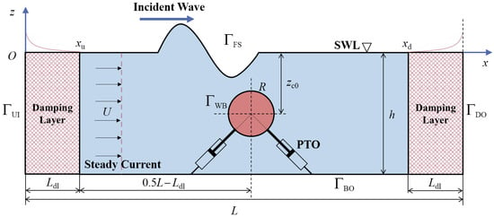
Figure 1.
A schematic representation of the NWT adopted herein.
2.2. Governing Equation and Boundary Conditions
Under the assumptions of ideal fluid, irrotational flow, negligible flow separation, and weak current conditions (characterized by small Keulegan–Carpenter numbers), a rigorous formulation of this problem is possible within the framework of potential flow theory [18,25,33]. Consequently, a velocity potential whose gradient represents the fluid velocity field can be derived. Then we have
where u and w denote the horizontal and vertical velocity of the fluid particle, respectively.
Considering a uniform steady current U along the positive x-direction, the above potential can be decomposed into steady and unsteady components such that [18,24]
where represents the unsteady velocity potential. Based on potential flow theory, is governed by the two-dimensional Laplace equation, so that
The boundaries of NWT, as shown in Figure 1, include the upstream inlet boundary , the free surface boundary , the downstream outlet boundary , the bottom boundary , and the wetted body surface boundary . The corresponding boundary conditions (BCs) are given by
where is the outward unit normal vector on the boundary, the velocity potential of the incident wave, the surface elevation, g the gravitational acceleration, the atmosphere pressure, and the seawater density. Note that the downstream boundary is treated as a rigid wall with the application of a damping layer, which is discussed in detail in Section 3. In Equation (9), denotes the linear velocity vector of the cylinder. In the present simulation, the submerged cylinder that experiences both regular waves and uniform currents only surges and heaves. Since the submerged cylinder undergoes a time-dependent motion, the boundary condition expressed by Equation (9) must be enforced on its instantaneous surface for every time step.
Rather than directly solving , it is more efficient to first determine its unsteady component . By substituting Equation (2) into Equation (3) and applying Equations (4)–(9), the boundary value problem (BVP) for is formulated as follows:
with the following initial conditions:
Note that the last two terms on the right of Equation (13) are neglected as they do not affect the final results.
2.3. Wave Forces on the Submerged Cylinder
In order to determine the motion of the submerged cylinder, it is crucial to accurately calculate its wave-induced loads. The hydrodynamic pressure on the wetted cylinder surface is determined from the following unsteady Bernoulli equation:
Substituting Equation (2) into Equation (17) yields
where all terms appearing on the right side except () are known once the solution to the BVP of is obtained. As concluded by Koo & Kim [25], the finite difference method for computing is only suitable for wave diffraction and radiation simulations. This method may lead to numerical instability for the simulation of waves interacting with freely floating bodies, as both the fluid motion and the body motions need to be solved simultaneously. To overcome this difficulty in calculating , the so-called acceleration potential method [34] is applied. The temporal derivative of , or , is also governed by the Laplace equation in the fluid domain. Then satisfies
Similarly to , another boundary value problem for is formulated, and the corresponding BCs are summarized as follows:
Note that the BC on the free surface, i.e., Equation (21), is derived straightforwardly from Equation (13) after neglecting the constant terms. Moreover, as seen in Equation (23), the body surface BC derived for a current-free environment holds irrespective of the presence of a steady uniform current. Therefore, the implicit kinematic body BC formulated by Tanizawa [34] still holds for the present current-affected acceleration field, such that
where is the moving body’s linear acceleration and represents the magnitude of the curvature at a point on the body surface. Since the submerged cylinder’s acceleration () cannot be determined a priori without solving the equations of motion, this kinematic BC on the body surface is implicit. The final two terms in Equation (24) characterize the influence of the velocity field on the acceleration field, which can be resolved by obtaining the solution of the BVP for the velocity potential . To evaluate the last term in Equation (24), the following expression is used instead of direct numerical differentiation:
Instead of the numerical differentiation method used by Koo & Kim [25], analytical determination of the second-order term, as expressed in Equation (25), is achievable through the desingularized boundary integral equation method. This method is described in Section 3.
Once the acceleration potential is obtained by solving the above BVP, the pressure follows from Equation (18). Thus, the hydrodynamic force acting on the submerged cylinder is given by
2.4. Motion of the Submerged Cylindrical WEC
Since the linear acceleration in Equation (24) is unknown unless the equation of motion of the submerged cylinder is solved, it is necessary to solve simultaneously the equation of motion and the boundary value problem for . In the present case with the submerged cylinder WEC, only the two degrees of freedom, i.e., the surge and heave, are considered. According to Newton’s second law, the equation of motion of the WEC device can be written as
where is the mass of the submerged cylinder, the horizontal hydrodynamic force, and the vertical hydrodynamic force.
We assume that the present WEC is tuned at the frequency , i.e., the wave energy absorption efficiency is maximized at this frequency for the current-free scenario based on the linearized water wave theory. The spring and damper constants and (i = x or z) are determined by [11]
where and are the hydrodynamic added mass and damping coefficients at the tuned frequency , respectively.
2.5. Hydrodynamic Efficiency of the Submerged Cylindrical WEC
Once the motion of the submerged cylindrical WEC is determined in the time domain, the mean power absorbed by the WEC device over one wave period T is given by [16,30]
The capture efficiency of the WEC is then defined by [11]
where the mean power flux of the incident waves per unit width, , is given by [35]
with and denoting the wave length and wave number in the absence of current.
3. Numerical Implementation
3.1. Time Stepping of the Free Surface
To capture the instantaneous free surface in the time domain, the mixed Eulerian–Lagrangian approach is adopted [36]. The substantial derivative can be expressed as , where denotes the node velocity. This study implements a material-node scheme whereby nodes on the free surface are assumed to track the motion of fluid particles. Using Equation (2), the node velocity is given by
Thus, the fully nonlinear kinematic and dynamic free surface BCs are reformulated within the Lagrangian framework through the application of Equation (32) in conjunction with Equations (5) and (6), yielding
Additionally, the horizontal nodal velocity on the free surface, , is then given by
With Equations (33)–(35), the free surface can now be tracked at any instant upon solving the boundary value problem for . To prevent free surface nodes from piling up at stagnation points, a regridding scheme is implemented [37]. Moreover, a five-point Chebyshev smoothing technique is implemented to smooth the surface elevation and velocity potential, effectively mitigating saw-tooth numerical instabilities [36].
For long-time simulations of waves interacting with a freely floating body using the NWT, it is crucial to eliminate both the re-reflection of upstream-traveling waves at the inlet boundary and the reflection of downstream-propagating waves at the outlet boundary, treated as a rigid wall. In this way, the radiation condition can be achieved at the far-field. Therefore, it is possible to obtain periodic steady body motions with long-time simulations with the present finite-length NWT [30,38,39]. Damping zones are implemented at both the upstream and downstream boundaries of the NWT in this investigation, as shown by the cross-hatched regions in Figure 1. These damping layers are numerically implemented by introducing an artificial viscous term into the free surface BCs.
The upstream damping zone is tailored to absorb only waves reflected by the floating structure, ensuring that incident waves remain unaltered. Consequently, the free surface BCs in the Lagrangian frame, as given by Equations (33) and (34), are modified as follows:
Here, denotes the tunable damping factor, which is defined as . , , , and are the terminal horizontal coordinate of the damping layer, the tuning factor, the damping layer length, and the current-free circular wave frequency, respectively. Based on the coordinate system shown in Figure 1, the ending abscissa is simplified to . In this study, is set as 1.0 and is chosen to be greater than one wavelength according to Ref. [40]. The artificial damping terms, and , represent the differences in surface elevation and velocity potential between total waves and incident waves, respectively. Here, and are the linear analytical solutions of surface elevation and velocity potential, respectively, for pure regular waves [41].
For the downstream region near the right vertical boundary, the free surface BCs in the Lagrangian frame are modified as follows:
Here, is defined as . represents the initial horizontal coordinate of the damping layer. The artificial damping terms and represent the surface elevation and velocity potential of the transmitted waves, respectively.
3.2. Desingularized Boundary Integral Equation Method
Numerical solutions for both the unsteady velocity potential and the acceleration potential are obtained in this study by applying the indirect desingularized boundary integral equation method (DBIEM) in the Eulerian frame. This method has been widely used in previous studies, including Refs. [18,24,42,43,44]. In the indirect desingularized method, the velocity or acceleration potential in the fluid domain is derived by integrating contributions from all Rankine sources distributed along an integration boundary located just beyond the physical domain, such that
Here, and represent a field point and a source point, respectively, and denotes the strength of the Rankine source positioned at . The Green function, denoted as , obeys the Laplace equation across the entire fluid region, as each of the Rankine sources resides outside the physical boundary. The expression of this function is provided later in this section.
The Rankine source strengths are determined through enforcement of the fluid domain boundary conditions. For the unsteady velocity potential , all BCs except those on the free surface boundary are given by Equations (11), (14), and (15). On these boundaries, the normal derivatives of the velocity potential are specified, which correspond to Neumann-type BC. For the instantaneous free surface , a Dirichlet-type BC is applied, specifying the velocity potential at each time step as described in Section 3.1. Substituting Equation (42) into these boundary conditions yields
where the superscripts “N” and “D” refer to the Neumann- and Dirichlet-type boundaries, respectively. The Neumann-type boundary for the present BVP is denoted as and the Dirichlet-type boundary consists of . and denote the prescribed normal gradient of the velocity potential and the specified velocity potential, respectively.
Equation (42) is solved numerically via the indirect formulation of DBIEM, where the boundary conditions are satisfied at the collocation points along the boundary, say with a total number and with a total number . Moreover, instead of continuous, a total number of isolated Rankine sources along the integration boundaries and are applied for simplification. Hence, Equation (43) is replaced by the following discrete form:
Applying Equation (44) for each collocation point, a total number of equations are formulated and hence linear algebraic matrix equations can be determined to solve the unknown Rankine sources’ strength. This scheme provides the means to obtain the solution for by addressing the corresponding BVP.
To avoid placing Rankine sources along the flat sea bottom (), we choose the following Green function:
Here, corresponds to the mirror image of the Rankine source with respect to the bottom boundary. If in the coordinate system, then its mirror about is given by . The zero-flux condition at the bottom boundary, given by Equation (8), is naturally enforced through this formulation. Hence, no discretisation on the bottom boundary is required, which can improve the computation efficiency by reducing the number of isolated Rankine sources.
For the BVP for , the implicit kinematic BC of the body surface given by Equation (24) can be converted into an integral equation in which only the Rankine source strength is unknown by substituting Equations (18), (26), (27), and (42). Details of this numerical method can be found in Ref. [42].
The ordinary differential equations given by Equations (36)–(39) are adopted for updating the free surface. To solve the motion response of the submerged cylinder in the time domain, time integration is performed on the equation of motion given by Equation (27). Following Wang et al. [42], the fourth-order Adams–Bashforth–Moulton predictor–corrector approach is employed for time marching.
3.3. Nonlinear Stokes Wave Theory
To generate waves in the present NWT, incident wave velocity profiles must be fed along the upstream inlet boundary . This study adopts second-order Stokes wave theory to represent the incident wave through its velocity potential and surface elevation, such that
where k denotes the current-affected wave number, calculated by using the following modified wave dispersion relationship [25,32]:
To improve simulation stability and accelerate convergence to steady state, a time-varying ramp function is introduced:
where denotes the modulation time. The variation of the ramp function with time is shown in Figure 2. Here, the modulate time is set to two times the wave period. It can be seen that the value of is smoothly shifted from 0 to 1 when , and then it is held fixed thereafter.
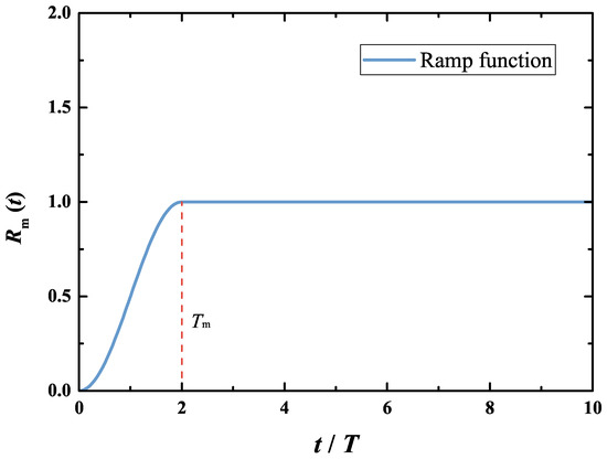
Figure 2.
Variation of the ramp function with time used in the present study.
4. Results and Discussions
4.1. Model Validation
To validate the present NWT, it is applied to investigate the hydrodynamic performance of the submerged Bristol cylinder WEC in pure waves. The setup of the NWT is similar to the one shown in Figure 1, with the exception that the steady current is absent (). For each case, the total length and the length of the two damping layers are taken as and , respectively. Since the free surface length is constant throughout the simulation, a semi-Lagrangian approach is used for its time stepping in this section [32]. According to Davis’s model experiments [15], the submerged cylinder has radius m, still water depth m, and initial submergence depth . Under the neutral buoyancy assumption at the initial instant, the cylinder mass is determined as in the two-dimensional NWT. The spring and damping constants and () in the PTO mechanism are determined by Equation (28) with the tuned frequency rad/s (corresponding to s for full-scale WEC device). The hydrodynamic added mass and damping coefficients, and (), are computed using the analytical solution proposed by Evans & Porter [45]. For the submerged circular cylinder with submergence , the results of these two coefficients are presented in Figure 3. The chosen and for the tuned frequency are also plotted by the stars. Therefore, the spring and damper constants in the PTO mechanism are set as N/m and N·s/m (). After sensitivity tests, the NWT boundaries are discretized by a total of 960 nodes, including 800 nodes along the free surface (100 nodes per wave length), 60 nodes along both the upstream inlet and downstream outlet boundaries, and 40 nodes on the submerged cylinder wetted surface. The time step is equal to . The wave height is taken as m.
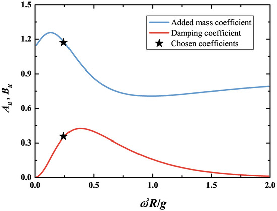
Figure 3.
Variation of the hydrodynamic added mass and damping coefficients ( and ) against dimensionless wave frequency for the submerged circular cylinder of .
Figure 4 shows the steady-state trajectories of the cylinder center in pure regular waves for three different wave frequencies, i.e., rad/s, 8.17 rad/s, and 10.05 rad/s. According to the linear theoretical analysis of Evans et al. [11], the induced motion of the cylinder center is expected to be circular. However, the cylinder center trajectories are clearly not perfectly circular in the present fully nonlinear simulation, as seen in Figure 4. For instance, the motion amplitude ratio between the heave and surge directions, , is equal to approximately 70% for rad/s, which means the amplitude of the heave direction is much smaller than that of the surge direction. In this case, the intermediate water depth is about . Hence, the rigid bottom’s restriction on the heave motion of the submerged cylinder becomes more apparent. This has also been noticed by other researchers, such as Guerber et al. [46] and Abbasnia & Guedes Soares [38].
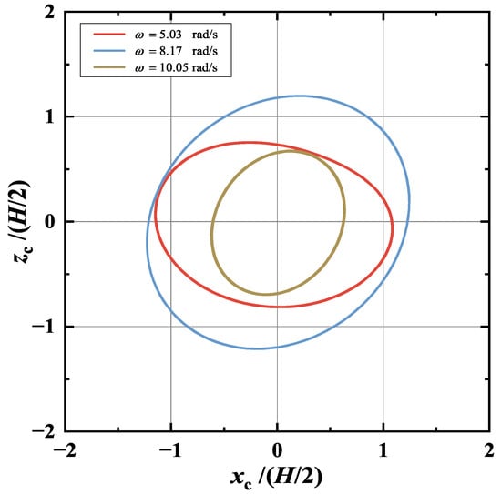
Figure 4.
Steady-state trajectories of the cylinder center in pure regular waves of m for three different wave frequencies rad/s, 8.17 rad/s, and 10.05 rad/s.
The time histories of the captured wave power by the submerged Bristol cylinder WEC in pure regular waves with m and rad/s are illustrated in Figure 5. Apart from the total power (), the power absorbed in both the surge and the heave directions ( and ) are also plotted. and are also determined with Equation (29) only considering the surge or heave motion. For clear illustration, Figure 5a,b give the results of the power curves for and , respectively. After about , the time series of wave power captured by the WEC becomes steady. Hence, only this part of the data is taken for the assessment of the mean extracted power. Moreover, it is observed that the contribution of absorbed power made by the surge motion is slightly larger than that of the heave motion. Further, the same numerical simulation is conducted for six other wave frequencies, including rad/s, 8.8 rad/s, 7.54 rad/s, 6.91 rad/s, 6.28 rad/s, 5.65 rad/s. In all of these simulations, the wave height is kept constant at m; therefore, the wave steepness is in the range of . Figure 6 illustrates the comparison of the hydrodynamic efficiency (E) of the submerged Bristol WEC between the present numerical (red line with symbol), linear analytical (light blue line) [11], and experimental results (black box symbol) [15]. The results show that the present numerical model closely matches the experimental results in the long-wave regime rad/s. For the wave regime outside this range, i.e., 5.03 rad/s rad/s, the predicted efficiency by the linear analytical model substantially deviates from the experimental one. Theoretically, the submerged Bristol WEC achieves a maximum efficiency of at the tuned frequency rad/s, as depicted by Figure 6. However, the peak efficiency observed experimentally is reduced to approximately . Moreover, this efficiency occurs at the wave frequency rad/s, which shows a clear shift from the tuned frequency . Compared with the analytical one, the present fully nonlinear model results can better predict the resonant frequency and the maximum efficiency of the WEC. The numerical results show a 20.6% discrepancy in compared to the experimental data; however, they align considerably more closely than linear analytical predictions, which deviate by 56.7%. However, the numerical model’s prediction of resonant frequency ( rad/s) aligns with experimental observations. Rather than fixed in the present simulation, both the spring and damper constants ( and , ) are adjusted to obtain the maximum trajectory in the experiments of Davis [15]. This appears to be the reason for the deviation between the numerical predictions and the experimental observations. Moreover, the effect of fluid viscosity is also neglected in the present numerical model. Through the above simulation of the submerged cylindrical WEC in waves, the established NWT is of convincing capability to predict the hydrodynamics of nonlinear wave–current–body interaction.
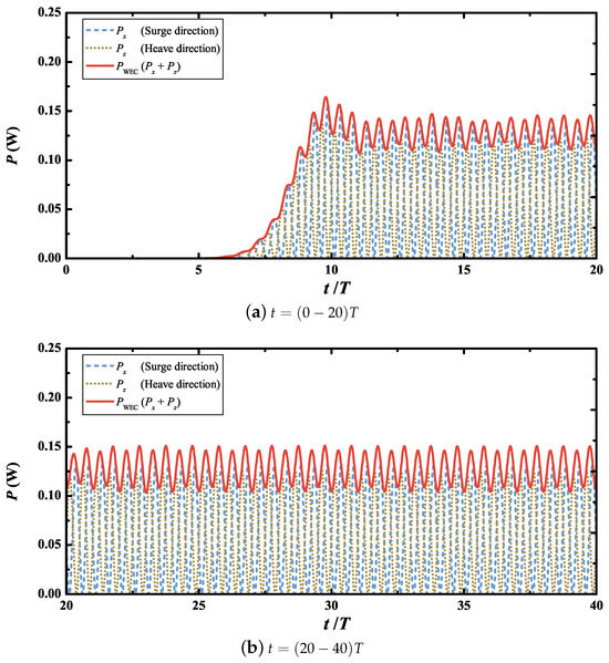
Figure 5.
Time histories of the captured wave power by the submerged Bristol cylinder WEC in pure regular waves of m and rad/s.
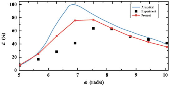
Figure 6.
Comparison of the hydrodynamic efficiency of the submerged Bristol WEC in pure waves between the present numerical, linear analytical, and experimental results.
4.2. Performance of the Submerged Cylindrical WEC Under Combined Wave–Current Conditions
Upon validation of the present NWT, it is employed to simulate the hydrodynamic behavior of a submerged cylinder WEC under combined wave–current conditions, as described in this section. As shown in Figure 1, a submerged cylinder is initially neutrally buoyant at a submergence of , meaning the mass of the cylinder is . The spring and damper constants of the linear PTO mechanism and () are predetermined using Equation (28). For this study, the dimensionless tuned frequency is = 1.0. The hydrodynamic coefficients and are obtained using the multipole expansion method [45]. With these calculated spring and damper constants for the linear PTO mechanism, the motion of the cylinder interacting with both regular waves and steady uniform currents can be evaluated using the present NWT.
Referring to [30,39], the NWT used in this simulation has the following dimensions: , , and . The total simulation time is 20T, including a 4-T modulation time applied in the time-varying ramp function, that is, . Through a convergence test, a time step of is chosen, 50 nodes on the cylinder surface, and 125 nodes per wave length on the free surface, which are found to be appropriate. In the following subsection, the influences of wave height, current speed, and PTO mechanism parameters on the hydrodynamic performance of the WEC device under combined wave–current conditions are investigated.
4.2.1. Effects of Wave Height
When the submerged WEC device is subjected to moderate waves, the wave steepness can alter the associated flow field, thus affecting the motion of the cylinder. To better understand the effect of wave nonlinearity on the hydrodynamic performance of the WEC, this section explores the effect of wave height on the extracted power under combined wave–current conditions. The wave height in this study ranges from = 0.02 to 0.14. The dimensionless wave frequency of the incident wave is set at = 0.5. These wave conditions are chosen based on previous studies on the Brystol WEC device by Evans et al. [11] and Davis [15]. Moreover, to ensure numerical stability in the present fully nonlinear simulation, the maximum wave height is chosen at H = 7 mm, which corresponds to . The parameters of the PTO mechanism, including the spring and damper constants, are computed using Equation (28) in which the dimensionless tuned frequency is selected at = 1.0. Three steady current scenarios are considered: the co-flowing current with , the current-free with , and the opposing current with . Here, the dimensionless current speed, or the Froude number, is defined as .
Figure 7 shows the variations in the dimensionless extracted power of the submerged WEC device under different steady currents as a function of wave height. It is evident that the extracted power decreases moderately with increasing wave height. As the wave height increases from to , the relative reductions in the dimensionless mean extracted power are approximately 8.3%, 10.5%, and 14.3% for the scenarios of co-flowing current (), current-free (), and opposing current (), respectively. To further illustrate the influence of wave height on the extracted power, the steady-state time histories of the dimensionless extracted power for the three wave heights , 0.08, and 0.02 are compared in Figure 8, with horizontal lines indicating the mean power for each case. Compared with the smallest wave height (), the dimensionless mean extracted power decreases by about 2.6% and 8.3% for larger wave heights and , respectively, for the case of co-flowing current . However, for the opposing-current case with , the reductions are more pronounced, reaching approximately 5% and 14.3% for and , respectively. The steady-state trajectories of the cylinder center predicted by present simulations are shown in Figure 9. The results indicate that the cylindrical WEC experiences the largest orbital motions (relative to the wave height) with the smallest wave height. As expected, the suppression of motion in larger waves reduces the efficiency of wave power extraction by the WEC. Moreover, it is observed that the vertical oscillation around is noticeably asymmetric, with the positive amplitude being larger than the negative, particularly for the opposing-current case (see Figure 9b). This may be attributed to the substantial difference between the free surface and rigid bottom BCs, which induces a net drift force acting on the cylinder in the vertical direction [38].
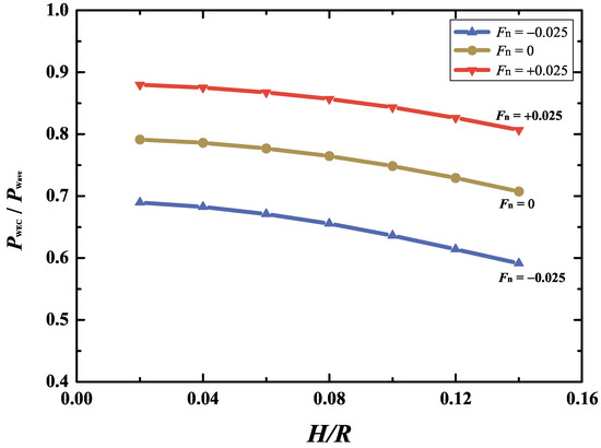
Figure 7.
Variations of the dimensionless mean extracted power versus wave height in different steady currents (, 0, and ).
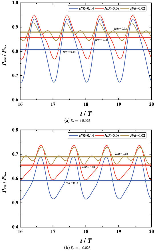
Figure 8.
Comparison of the steady-state time histories of the extracted power between different wave heights: (a) the co-flowing current and (b) the opposing current.
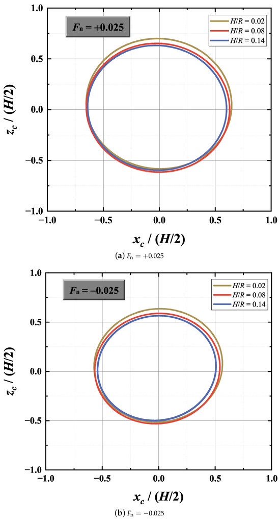
Figure 9.
Comparison of the steady-state time histories of the cylinder center trajectories between different wave heights: (a) the co-flowing current and (b) the opposing current.
From the perspective of linear wave theory, the dimensionless extracted power extracted by the WEC device remains constant for a given wave height. This is a consequence of neglecting nonlinear terms in the free-surface BCs (see Equations (5) and (6)) and in the unsteady hydrodynamic pressure (see Equation (17)). Moreover, unlike the instantaneous boundaries adopted in the present simulation, the linear boundary conditions are applied at fixed boundaries. The present results of fully nonlinear simulation, illustrated in Figure 7, may overestimate the wave power extraction capability of the WEC device. This results from the enhanced generation of higher-harmonic waves produced by wave–current–cylinder interactions under larger wave conditions. This is clearly illustrated in Figure 10, which compares the surface elevation at behind the cylinder for three wave heights, i.e., , 0.08, and 0.14. Moreover, this observation is consistent with the earlier experimental findings of Evans et al. [11] who investigated the hydrodynamic performance of the cylindrical WEC in pure wave conditions. As noted in Figure 7, the presence of a co-flowing current or opposing currents does not alter the overall trend of the dimensionless extracted power with respect to wave height.
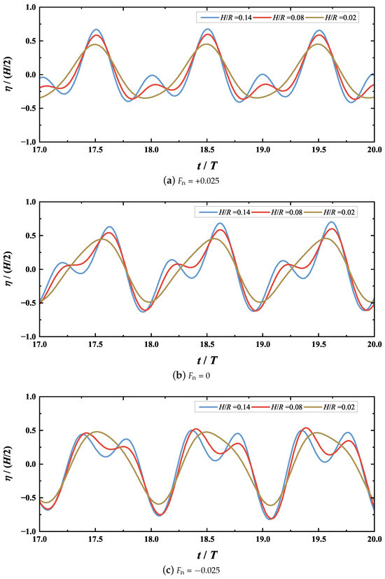
Figure 10.
Comparison of the surface elevation behind the cylinder at between different wave heights with (a) co-flowing current, (b) current-free, and (c) the opposing current.
4.2.2. Effects of Steady Current Velocity
Apart from the incident wave, the hydrodynamic load exerted on the cylindrical WEC device is also affected by the presence of currents. In this section, the hydrodynamic performance of the device is investigated under various steady currents imposed on a given wave field. The PTO mechanism parameters are identical to those used in the previous section. Three wave heights are considered, namely , 0.08, and 0.14. The wave frequency is fixed at = 0.5. The dimensionless mean extracted power by the submerged WEC device () for different dimensionless current velocities () is shown in Figure 11. Within the considered range of current velocity, i.e., , the mean extracted power increases almost linearly with the current velocity. The corresponding linear fitting results are represented by solid lines in Figure 11. The smallest R-squared value among these fits is approximately 99.6%, clearly demonstrating the linear relationship between and . This trend can be explained by the fact that the horizontal and vertical wave loads increase in the co-flowing current () and vice versa in the opposing current (), as illustrated in Figure 12. For simplicity, the hydrodynamic forces in both the surge and heave directions are shown only for . Similar findings observations were reported by Ref. [25] for the wave loads on a fixed box-type structure subjected to combined wave–current conditions. When the wave height increases from to , the growth rate of with increases moderately. This is evident from the comparison of the slopes of the three fitted lines in Figure 11.
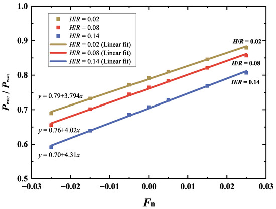
Figure 11.
Variations of the extracted power versus current velocities for the three wave heights , 0.08, and 0.14.
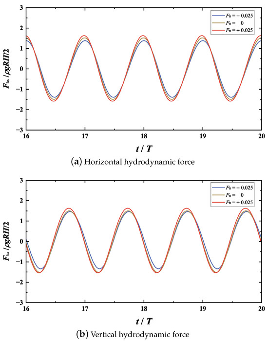
Figure 12.
Comparison of the steady-state time histories of the hydrodynamic forces between different current velocities for and .
Figure 13 shows the variation of the dimensionless extracted power with the dimensionless wave frequency for the co-flowing, current-free, and opposing currents. Here, the wave height is fixed at . For all three current conditions (, 0, and +0.025), the relationship of with follows a trend remarkably similar. That is, the mean extracted power first increases with wave frequency, reaches a maximum at , and then decreases as the frequency increases further. Although the PTO mechanism parameters are selected using the linear wave theory for pure waves, the corresponding wave frequency for the peak values of remains unchanged under different current conditions. Additionally, when the dimensionless wave frequency exceeds 0.335, i.e., , under the co-flowing current () are larger than that for current-free scenario () while the opposite occurs for the opposing current (). In contrast, for long waves with , the opposite trend is observed. Compared with the current-free case with , the mean extracted power is reduced by about 15.6% and increased by approximately 8.4% for the co-flowing and opposing currents, respectively. Figure 14 shows the comparison of the steady-state time histories of the hydrodynamic forces between different current velocities for . The difference in the amplitude of the horizontal hydrodynamic force between the three currents is relatively small. However, unlike the higher-frequency case of , the amplitude of the vertical hydrodynamic force decreases in the co-flowing current and increases in the opposing current. This probably explains why the extracted power of the WEC device is enhanced in long waves under opposing currents. In addition, the opposing current can amplify the incident wave amplitude, thereby further increasing the extracted wave power [27].
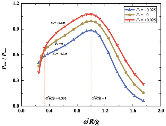
Figure 13.
Variations of the extracted power of the submerged WEC device versus wave frequencies for the three current velocities , 0, and .
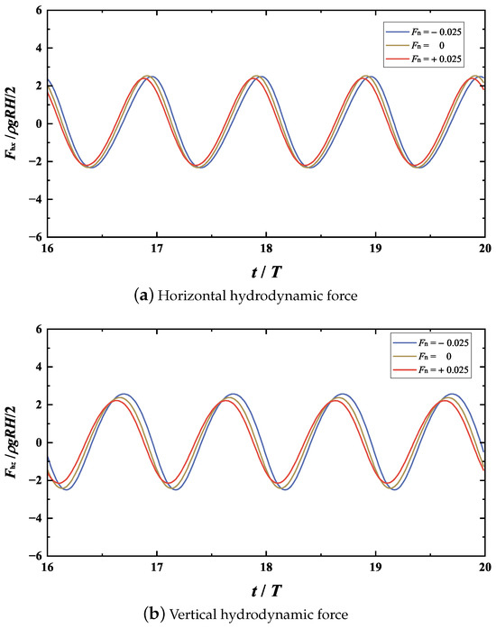
Figure 14.
Comparison of the steady-state time histories of the hydrodynamic forces between different current velocities for and .
4.2.3. Effects of PTO Mechanism Parameters
In this section, the effects of the PTO mechanism parameters on the hydrodynamic performance of the cylindrical WEC under combined wave–current conditions are examined. This is motivated by the experimental and numerical studies conducted by Davis [15] and Anbarsooz et al. [16], both of which emphasized that tuning the WEC converter plays a significant role in enhancing wave power extraction under pure wave conditions. In the aforementioned studies, the spring and damping constants of the PTO mechanism are determined by setting the tuned frequency at = 1.0 based on the analytical work of Evans et al. [11]. To avoid confusion in the following discussion, these two constants are denoted and , respectively. Note that the effect of current was not considered in the tuning process of the WEC device in previous studies. Therefore, it is of particular interest to independently examine the effects of the spring and damper constants and () on the extracted power. In the following simulations, the wave height and frequency are fixed at and , respectively.
Figure 15 shows the extracted power variations of the submerged WEC device with respect to the spring constant for three current velocities, , 0, and , where the damper constant is set as . The spring constants are non-dimensionalized with respect to . Similar variation trends of with the spring constant are observed under co-flowing, current-free, and opposing currents. Specifically, there exists an optimal spring constant for each current velocity. For the case of co-flowing current with , the maximum extracted power occurs at a larger spring constant, i.e., . In contrast, for the opposing-current case, the optimal spring constant () is smaller than that of the current-free case. This shift may be attributed to the variation of the added mass under different current conditions, which alters the required PTO stiffness to achieve resonance. Therefore, in addition to the wave frequency, further tuning of the spring constant for each current velocity is demonstrated to be beneficial to maximize wave power extraction.
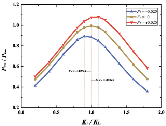
Figure 15.
Variations of the extracted power versus spring constant for the three current velocities , 0, and .
The comparison of the extracted power of the submerged WEC device with respect to the spring constant for different wave heights is presented in Figure 16. As shown in the figure, the optimal spring constant is largely insensitive to the wave height when the current velocity is fixed. Among the three current velocities, the effect of wave nonlinearity is most pronounced for the opposing current . In this case, the wave length is shortened and the amplitude is enlarged compared with the current-free scenario. Consequently, the wave steepness under the opposing current is the greatest among the three cases, leading to the most significant difference in the extracted power across the three wave heights.
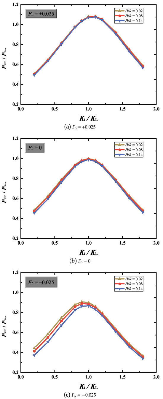
Figure 16.
Comparison of the extracted power between different wave heights with (a) co-flowing current, (b) current-free, and (c) the opposing current.
Figure 17 illustrates the variation in the extracted power of the submerged WEC device with respect to the damper constant for the three current velocities , 0, and . The spring constant and the wave height are fixed at and , respectively. In this figure, the damper constants are non-dimensionalized with respect to . For each current velocity, the curves of exhibit similar trends with the dimensionless damper constant. As expected, when the damping constant is chosen at , the WEC device does not absorb the wave energy, and thus . This can also be revealed from Equation (29). On the other hand, when the damping constant is increased to a relatively large value, such as , the motion of the submerged cylinder is significantly suppressed. Therefore, the damping constant must be carefully selected to maximize the extracted power of the WEC device. As seen in Figure 17, the optimal damper constants for all three current scenarios are indicated by dashed lines. For the co-flowing current, the maximum extracted power point shifts towards higher damper constant than that of the linear wave theory, whereas the opposing current shifts it to smaller values. This suggests that the current effect is considered for tuning the WEC once the damper constant in the PTO mechanism is controllable for maximum wave power absorption. Compared with Figure 15, the dimensionless extracted power appears to be more sensitive to variations in the spring constant than in the damper constant, particularly when both are close to the theoretical values from linear analysis, i.e., and .
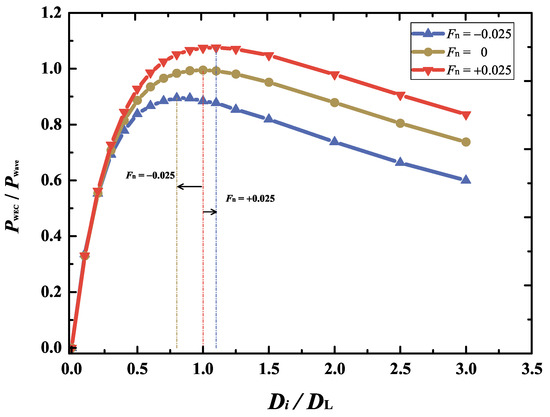
Figure 17.
Variations of the dimensionless extracted power versus damper constant for the three current velocities , 0, and .
Given the significant impact of PTO parameters on the optimal tuning of the WEC device mentioned above, the PTO mechanism design is altered under combined wave–current conditions. Compared with current-free conditions, the optimal spring and damper constants should be chosen at a higher value for the co-flowing current and vice versa for the opposing current.
5. Conclusions
A potential flow theory-based fully nonlinear 2D NWT is developed in the time domain to investigate the hydrodynamic behavior of a submerged circular cylindrical WEC device under combined wave–current conditions. A coupled numerical approach integrating the desingularized boundary integral equation method with the implicit acceleration potential method is developed to solve the model. This method enables simultaneous prediction of wave loads exerted on the device and its motion response. After validation, the present numerical model is employed to investigate the hydrodynamic performance of a submerged circular cylindrical WEC device in combined waves and currents. The influences of wave height, current speed, and parameters of the PTO mechanism on the extracted wave power are analyzed in detail, and the following conclusions can be made:
(1) With increasing wave height, the dimensionless mean extracted wave power is reduced by as much as 14.3% for the scenario of an opposing current (). The presence of either the co-flowing current or the opposing current does not alter the variation trend of the dimensionless wave power against the wave height.
(2) Within the range of the current velocity considered, i.e., , the mean extracted power increases almost linearly when the current velocity increases with . For dimensionless wave frequencies above 0.335, the extracted power under a co-flowing current exceeds that of the current-free case; conversely, an opposing current yields lower power. In contrast, at lower frequencies , the opposite trend is observed.
(3) Relative to the current-free case, the co-flowing current shifts the maximum power point to moderately larger spring and damper constants, whereas the opposing current shifts it to smaller values.
It should be noted that the present study employs potential flow theory, which requires the current to be weak. For cases that violate this assumption, the numerical model based on the Navier–Stokes equations should be employed to account for turbulence, viscosity, flow separation, and possible wave breaking. Moreover, the capability of numerical models to simulate the dynamic response of the WEC device in realistic irregular waves at sea is also needed to better clarify its high-efficiency operation mechanism. However, the present preliminary simulations provide valuable insight for discovering the hydrodynamic behavior of a submerged cylindrical WEC device under combined wave–current conditions. The wave height, current speed, and parameters of the PTO mechanism are found to substantially impact the power extraction ability of the WEC device. The findings in this paper serve as useful guidelines for the design of the WEC device deployed in seas where waves and currents coexist.
Author Contributions
Conceptualization, Y.X. and L.W.; methodology, L.W.; software, C.T. and B.Z.; validation, C.T. and L.W.; formal analysis, C.T. and L.W.; investigation, C.T. and L.W.; resources, Y.X. and L.W.; data curation, B.Z.; writing—original draft preparation, L.W.; writing—review and editing, Y.X.; visualization, L.W.; supervision, Y.X.; project administration, B.Z.; funding acquisition, Y.X. and L.W. All authors have read and agreed to the published version of the manuscript.
Funding
This research was funded by the National Key Research and Development Program of China (Grant No. 2023YFC3106902) and the National Natural Science Foundation of China (Grant No. 51809209).
Data Availability Statement
The raw data supporting the conclusions of this article will be made available by the authors on request.
Acknowledgments
The above funding supports are gratefully acknowledged by the authors.
Conflicts of Interest
The authors declare no conflicts of interest.
References
- Falcão, A. Wave energy utilization: A review of the technologies. Renew. Sust. Energ. Rev. 2010, 14, 899–918. [Google Scholar] [CrossRef]
- López, I.; Andreu, J.; Ceballos, S.; de Alegría, I.; Kortabarria, I. Review of wave energy technologies and the necessary power-equipment. Renew. Sust. Energ. Rev. 2013, 27, 413–434. [Google Scholar] [CrossRef]
- Stromstedt, E.; Eriksson, M.; Sundberg, J.; Stalberg, M.; Waters, R.; Leijon, M.; Danielsson, O.; Svensson, O.; Gustafsson, S. Experimental results from sea trials of an offshore wave energy system. Appl. Phys. Lett. 2007, 90, 034105. [Google Scholar] [CrossRef]
- Elwood, D.; Schacher, A.; Rhinefrank, K.; Prudell, J.; Yim, S.; Amon, E.; Brekken, T.; von Jouanne, A. Numerical modeling and ocean testing of a direct-drive wave energy device utilizing a permanent magnet linear generator for power take-off. In Proceedings of the ASME 2009 28th International Conference on Ocean, Offshore and Arctic Engineering, Honolulu, HI, USA, 31 May–5 June 2009. [Google Scholar]
- Weber, J.; Mouwen, F.; Parish, A.; Robertson, D. Wavebob-research & development network and tools in the context of systems engineering. In Proceedings of the 8th European Wave and Tidal Energy Conference, Uppsala, Sweden, 7–10 September 2009. [Google Scholar]
- Zhang, Y.; Li, D.; Hong, S.; Zhang, M. Design of a new oscillating-buoy type wave energy converter and numerical study on its hydrodynamic performance. Brodogradnja 2023, 74, 145–168. [Google Scholar] [CrossRef]
- Martic´, I.; Degiuli, N.; Grlj, C. Scaling of wave energy converters for optimum performance in the Adriatic Sea. Energy 2024, 294, 130922. [Google Scholar] [CrossRef]
- Crowley, S.; Porter, R.; Evans, D. A submerged cylinder wave energy converter. J. Fluid Mech. 2013, 716, 566–596. [Google Scholar] [CrossRef]
- Crowley, S.; Porter, R.; Evans, D. A submerged cylinder wave energy converter with internal sloshing power take off. Eur. J. Mech. B Fluids 2014, 47, 108–123. [Google Scholar] [CrossRef]
- Sergiienko, N.; Cazzolato, B.; Ding, B.; Hardy, P.; Arjomandi, M. Performance comparison of the floating and fully submerged quasi-point absorber wave energy converters. Renew. Energy 2017, 108, 425–437. [Google Scholar] [CrossRef]
- Evans, D.; Jeffrey, D.; Salter, S.; Taylor, J. Submerged cylinder wave energy device: Theory and experiment. Appl. Ocean Res. 1979, 1, 3–12. [Google Scholar] [CrossRef]
- Gardner, F. Learning experience of AWS pilot plant test offshore Portugal. In Proceedings of the 6th European Wave and Tidal Energy Conference, Glasgow, UK, 29 August–2 September 2005. [Google Scholar]
- Mann, L.; Burns, A.; Ottaviano, M. CETO, a carbon free wave power energy provider of the future. In Proceedings of the 7th European Wave and Tidal Energy Conference, Porto, Portugal, 11–13 September 2007. [Google Scholar]
- Saruwatari, A.; Ingram, D.; Cradden, L. Wave-current interaction effects on marine energy converters. Ocean Eng. 2013, 73, 106–118. [Google Scholar] [CrossRef]
- Davis, J. Wave energy absorption by the Bristol cylinder-linear and non-linear effects. Proc. Inst. Civ. Eng. 1990, 89, 317–340. [Google Scholar] [CrossRef]
- Anbarsooz, M.; Passandideh-Fard, M.; Moghiman, M. Numerical simulation of a submerged cylindrical wave energy converter. Renew. Energy 2014, 64, 132–143. [Google Scholar] [CrossRef]
- Kim, M.; Celebi, M.; Park, J. A numerical wave tank for nonlinear wave simulations. In Proceedings of the 1997 3rd International Symposium on Ocean Wave Measurement and Analysis (WAVES97), Virginia Beach, VA, USA, 3–7 November 1997. [Google Scholar]
- Kim, M.; Celebi, M.; Kim, D. Fully nonlinear interactions of waves with a three-dimensional body in uniform currents. Appl. Ocean Res. 1998, 20, 309–321. [Google Scholar] [CrossRef]
- Grue, J.; Palm, E. Wave radiation and wave diffraction from a submerged body in a uniform current. J. Fluid Mech. 1985, 151, 257–278. [Google Scholar] [CrossRef]
- Wu, G.; Eatock Taylor, R. Hydrodynamic forces on submerged oscillating cylinders at forward speed. Proc. R. Soc. London Ser. A Math. Phys. Eng. Sci. 1987, 414, 149–170. [Google Scholar]
- Zhao, R.; Faltinsen, O. Interaction between waves and current on a two-dimensional body in the free surface. Appl. Ocean Res. 1988, 10, 87–99. [Google Scholar] [CrossRef]
- Isaacson, M.; Cheung, K. Time-domain solution for wave-current interactions with a two-dimensional body. Appl. Ocean Res. 1993, 15, 39–52. [Google Scholar] [CrossRef]
- Kim, D.; Kim, M. Wave-current interaction with a large three-dimensional body by THOBEM. J. Ship Res. 1997, 41, 273–285. [Google Scholar] [CrossRef]
- Celebi, M. Nonlinear transient wave-body interactions in steady uniform currents. Comput. Meth. Appl. Mech. Eng. 2001, 190, 5149–5172. [Google Scholar] [CrossRef]
- Koo, W.; Kim, M. Current effects on nonlinear wave-body interactions by a 2D fully nonlinear numerical wave tank. J. Waterw. Port Coast. Ocean Eng. 2007, 133, 136–146. [Google Scholar] [CrossRef]
- Shao, Y.; Faltinsen, O. Fully-nonlinear wave-current-body interaction analysis by a harmonic polynomial cell method. J. Offshore Mech. Arct. Eng. 2014, 136, 031301. [Google Scholar] [CrossRef]
- Cheng, Y.; Ji, C.; Zhai, G.; Ma, Z. Fully nonlinear simulation of wave-current interaction with an oscillating wave surge converter. J. Mar. Sci. Technol. 2020, 25, 93–110. [Google Scholar] [CrossRef]
- Cheng, Y.; Ji, C.; Yuan, Z.; Atilla, I. Wave slamming on an OWSC wave energy converter in coupled wave-current conditions with variable-depth seabed. China Ocean Eng. 2021, 35, 646–661. [Google Scholar] [CrossRef]
- Capasso, S.; Tagliafierro, B.; Martínez-Estévez, I.; Altomare, C.; Gómez-Gesteira, M.; Göteman, M.; Viccione, G. Development of an SPH-based numerical wave-current tank and application to wave energy converters. Appl. Energy 2025, 377, 124508. [Google Scholar] [CrossRef]
- Wang, L.; Wu, Y.; Tang, H. Effects of wave-current interaction on a submerged wave energy converter. In Proceedings of the Twenty-Fifth International Ocean and Polar Engineering Conference, Kona, Big Island, HI, USA, 21–26 June 2015. [Google Scholar]
- Thomas, G. Wave-current interactions: An experimental and numerical study. Part 1. Linear waves. J. Fluid Mech. 1981, 110, 457–474. [Google Scholar] [CrossRef]
- Ryu, S.; Kim, M.; Lynett, P. Fully nonlinear wave-current interactions and kinematics by a BEM-based numerical wave tank. Comput. Mech. 2003, 32, 336–346. [Google Scholar] [CrossRef]
- Lin, P.; Li, C. Wave-current interaction with a vertical square cylinder. Ocean Eng. 2003, 30, 855–876. [Google Scholar] [CrossRef]
- Tanizawa, K. A nonlinear simulation method of 3-D body motions in waves (1st report). J. Soc. Naval Arch. Japan 1995, 178, 179–191. [Google Scholar] [CrossRef]
- Dean, R.; Dalrymple, R. Water Wave Mechanics for Engineers and Scientists; World Scientific Publishing Company: Singapore, 1991. [Google Scholar]
- Longuet-Higgins, M.; Cokelet, E. The deformation of steep surface waves on water—I. A numerical method of computation. Proc. R. Soc. Lond. Ser. A Math. Phys. Eng. Sci. 1976, 350, 1–26. [Google Scholar]
- Dommermuth, D.; Yue, D. Numerical simulations of nonlinear axisymmetric flows with a free surface. J. Fluid Mech. 1987, 178, 195–219. [Google Scholar] [CrossRef]
- Abbasnia, A.; Guedes Soares, C. Fully nonlinear simulation of wave interaction with a cylindrical wave energy converter in a numerical wave tank. Ocean Eng. 2018, 152, 210–222. [Google Scholar] [CrossRef]
- Koo, W.; Kim, M. Fully nonlinear wave-body interactions with surface-piercing bodies. Ocean Eng. 2007, 34, 1000–1012. [Google Scholar] [CrossRef]
- Contento, G.; Codiglia, R.; D’Este, F. Nonlinear effects in 2D transient nonbreaking waves in a closed flume. Appl. Ocean Res. 2001, 23, 3–13. [Google Scholar] [CrossRef]
- Tanizawa, K.; Naito, S. A study on parametric roll motions by fully nonlinear numerical wave tank. Int. J. Offshore Polar Eng. 1997, 8, 251–257. [Google Scholar]
- Wang, L.; Tang, H.; Wu, Y. Simulation of wave-body interaction: A desingularized method coupled with acceleration potential. J. Fluids Struct. 2015, 52, 37–48. [Google Scholar] [CrossRef]
- Cao, Y.; Schultz, W.; Beck, R. Three-dimensional desingularized boundary integral methods for potential problems. Int. J. Numer. Methods Fluids 1991, 12, 785–803. [Google Scholar] [CrossRef]
- Liu, C.; Huang, Z.; Tan, S. Nonlinear scattering of non-breaking waves by a submerged horizontal plate: Experiments and simulations. Ocean Eng. 2009, 36, 1332–1345. [Google Scholar] [CrossRef]
- Evans, D.; Porter, R. Wave-free motions of isolated bodies and the existence of motion-trapped modes. J. Fluid Mech. 2007, 584, 225–234. [Google Scholar] [CrossRef]
- Guerber, E.; Benoit, M.; Grilli, S.; Buvat, C. A fully nonlinear implicit model for wave interactions with submerged structures in forced or free motion. Eng. Anal. Bound. Elem. 2012, 36, 1151–1163. [Google Scholar] [CrossRef]
Disclaimer/Publisher’s Note: The statements, opinions and data contained in all publications are solely those of the individual author(s) and contributor(s) and not of MDPI and/or the editor(s). MDPI and/or the editor(s) disclaim responsibility for any injury to people or property resulting from any ideas, methods, instructions or products referred to in the content. |
© 2025 by the authors. Licensee MDPI, Basel, Switzerland. This article is an open access article distributed under the terms and conditions of the Creative Commons Attribution (CC BY) license (https://creativecommons.org/licenses/by/4.0/).