Article

Structural Response and Volume Change Characteristics of Tuna Cages Equipped with External Egg Collection Nets

1
Department of Maritime Police System, Gyeongsang National University, Tongyoung 53064, Republic of Korea
2
Department of Smart Fisheries Resource Management, Chonnam National University, Yeosu 59626, Republic of Korea
3
Subtropical Fisheries Research Institute, National Institute of Fisheries Science, Jeju 63068, Republic of Korea
*
Author to whom correspondence should be addressed.
J. Mar. Sci. Eng. 2025, 13(9), 1762; https://doi.org/10.3390/jmse13091762
Submission received: 7 August 2025 / Revised: 3 September 2025 / Accepted: 10 September 2025 / Published: 12 September 2025
(This article belongs to the Special Issue Marine Fishing Gear and Aquacultural Engineering)

Abstract

The installation of an egg collection net in the upper section of a Pacific bluefin tuna (Thunnus orientalis) cage (diameter 25 m × height 15 m) raises concerns regarding the potential compromise of cage stability due to the fine mesh size. This study addresses two primary questions: (1) How can the egg collection net be deployed effectively without undermining cage stability? (2) What are the effects of the egg collection net on the cage volume and shape under varying current conditions? To investigate these questions, a mass–spring interaction model was developed to simulate the contact behavior between net structures, and numerical simulations were performed under various current speeds and sinker weight conditions. The results indicate that optimal deployment is achieved when a sinker weight of 78.5 N per meter is applied along the lower perimeter of the egg collection net. The additional volume reduction induced by the egg collection net was minimal (0.01–0.54%), falling within the natural range of flow-induced fluctuations. These findings lay the groundwork for the development of more robust and efficient bluefin tuna aquaculture systems.

1. Introduction

The Pacific bluefin tuna (Thunnus orientalis) is a high-value species with strong global demand, particularly in Japan [1,2]. Rising sea surface temperatures linked to climate change have recently increased catches in South Korean waters [2,3]. This trend has accelerated the expansion of domestic aquaculture and related research efforts [4].
Full-cycle aquaculture requires control of all life stages: spawning, hatching, growth, and harvest. Among these, egg collection is critical because it directly influences survival and juvenile production [1,4]. Egg collection relies on the buoyancy of fertilized eggs. Fine-mesh nets or synthetic curtains are installed near the surface, either inside or outside the cage, to collect floating eggs [5,6]. The method is widely adopted due to its simple design and operation. However, these nets increase hydrodynamic resistance and may alter the structural response of the cage system. Reduced cage volume and instability are potential outcomes. Furthermore traditionally, the installation specifications for egg collection nets have been determined empirically, making it difficult to evaluate their proper deployment in underwater environments.
Previous studies have analyzed the hydrodynamic and structural behavior of fish cages under currents and waves. Examples include fluid–structure interaction analyses [7], dynamic response studies of floating cages [8], experiments on semi-submersible cages [9], CFD-based performance predictions [10], and analyses of self-submersible mooring cages under combined loading [11]. Most of this work, however, focused on single-net structures. Research on combined systems with additional nets is limited.
Egg collection nets can reduce the effective cage volume, restricting fish movement and potentially increasing mortality under strong currents. Quantitative evaluation of these effects is therefore necessary. This study investigates the structural response and volume change in tuna cages with external egg collection nets under varying currents. Specifically, this study addresses two primary questions: (1) how can egg collection nets be deployed effectively without compromising cage stability, and (2) what is the effect of the nets on cage volume and shape under different current conditions. A mass–spring contact model was developed to simulate the coupled behavior of cage and egg collection nets. Simulations were used to evaluate the influence of installation parameters and current speed on cage deformation and volume reduction. The results provide a basis for practical design and support the development of full-cycle aquaculture systems.
The paper is structured as follows. Section 2 describes the numerical model and simulation setup. Section 3 presents the results and discusses implications for cage stability and egg collection with limitations and future work. Section 4 provides conclusions.

2. Materials and Methods

The cage analyzed in the numerical simulation was a cylindrical structure with diameter 25 m and height 15 m, specifically designed for bluefin tuna aquaculture in the southern coastal waters of South Korea. Structural integrity was ensured by installing circular rims along both the top and bottom edges of the cage, with 24 vertical ropes interconnecting the upper and lower rims.
To prevent drifting and floating, two weights, each with an in-water weight of 245.3 N, were attached to the center of the bottom net. The cage net was composed of square-mesh polyethylene (PE) netting with a mesh size of 35.35 mm. Additionally, an egg collection net was mounted on the exterior of the upper section of the cage net. This collection net was made from polyethylene terephthalate (PET) square-mesh fabric with a mesh size of 818 μm. A schematic of the cage, including the attached egg collection net and detailed specifications, are shown in Figure 1 and Table 1, respectively.

2.1. Fish Cage System Modeling

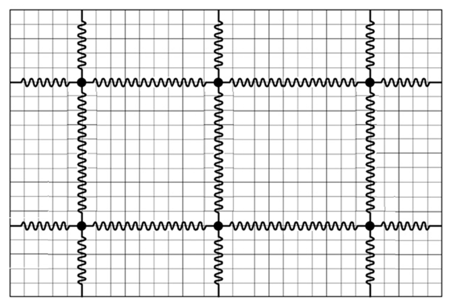
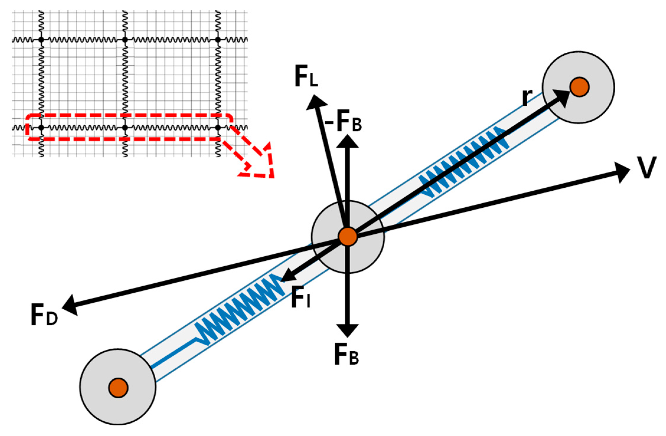
A mass–spring model was employed to analyze the underwater behavior of the cage [12,13,14]. In this model, the net twines and ropes are represented as springs, whereas the knots and rope junctions are modeled as mass points. Hydrodynamic and interaction forces are assumed to act exclusively at these mass points (Figure 2). Computational cost was reduced by adopting a mass-point grouping method [12], whereby multiple mass points forming the netting were aggregated into a reduced number of representative nodes (mass points) for calculation efficiency (Figure 2).
The motion of each mass point modeled in the mass–spring system is governed by Newton’s second law, which is expressed as follows:
m a + m q ¨ = F I + F E ,
where m a and m denote the added and intrinsic masses of a mass point, respectively. The sum of these two quantities constitutes the virtual mass, accounting for the hydrodynamic forces acting on the mass point when submerged in water. The variable q ¨ represents the acceleration of the mass point, whereas F I represents the interaction force between the mass points obtained from Equation (2).
F I = n i = 1 n E i A i r i l i l i ,
where r denotes the position vector of a mass point, n represents the unit vector in the direction of r, E represents the Young’s modulus of the twine or rope, l represents the initial length of the twine or rope segment comprising the mesh or rope, and i denotes the mass point connected to the mass point currently being calculated.
The external force FE comprises the submerged weight (FW), drag force (FD), and lift force (FL) acting on the mass point as follows:
F E = F W + F D + F L .
The drag and lift forces are expressed as follows:
F D = 1 2 C D ρ S V 2 n D ,
F L = 1 2 C L ρ S V 2 n L ,
where C D represents the drag coefficient, ρ represents the fluid density, S represents the reference area over which the fluid resistance acts, the unit vector n D represents the direction of the drag force, C L represents the lift coefficient, and n L represents the unit vector indicating the direction of the lift force, which is computed using Equation (6).
n L = V × ( V × N ) V × ( V × N ) ,
where velocity V represents the resultant of the mass point velocity vector V m and current velocity vector V w , expressed as follows:
V = V m + V w .
A detailed diagram of the mass–spring model, including the forces acting on the mass point, is shown in Figure 3.
The time-dependent positions of each mass point were determined by numerically integrating the equation of motion. The second-order ordinary differential equation (Equation (1)) was reformulated as two first-order ordinary differential equations for numerical integration as follows [14]:
q ˙ t = v ( t ) ,
v ˙ t = m + m a 1 ( F I + F E ) ,
where q ˙ ( t ) and v ˙ t represent the velocity and acceleration vectors of the mass point at time t, respectively. Numerical integration was performed using the fourth-order Runge–Kutta method with a time step of 0.00005 s. The equations utilized for the simulation were implemented in the C programming language within the Microsoft Visual Studio 2022 development environment. The resulting three-dimensional position data for each mass point were visualized as discrete points in virtual space using the OpenGL graphics library, whereas the springs connecting the mass points were represented as virtual lines.
Generally, for a cylindrical fish cage, the current flows through half of the net structure before passing through the remaining half. In the configuration modeled in this study, the egg collection net was positioned along the outer circumference of the cylindrical cage net. Consequently, in the section extending from the water surface down to 2.6 m, the current traversed four layers of netting in the following sequence: egg collection net → cage net → cage net → egg collection net. In the remaining depth range, where the egg collection net was absent, the current passed through two layers: cage net → cage net. As reported by Lee and Lee [15], the current velocity decreased each time it passed through the netting layer. The extent of velocity reduction was estimated using the empirical relationship proposed by Kim [16] as follows:
u r = U ( 1 1.54 ( S n S ) 1.47 ) ,
where u r represents the flow velocity after traversing the net, U represents the flow velocity before traversing the net, Sn indicates the projected area of the net, and S signifies the area occupied by the net.
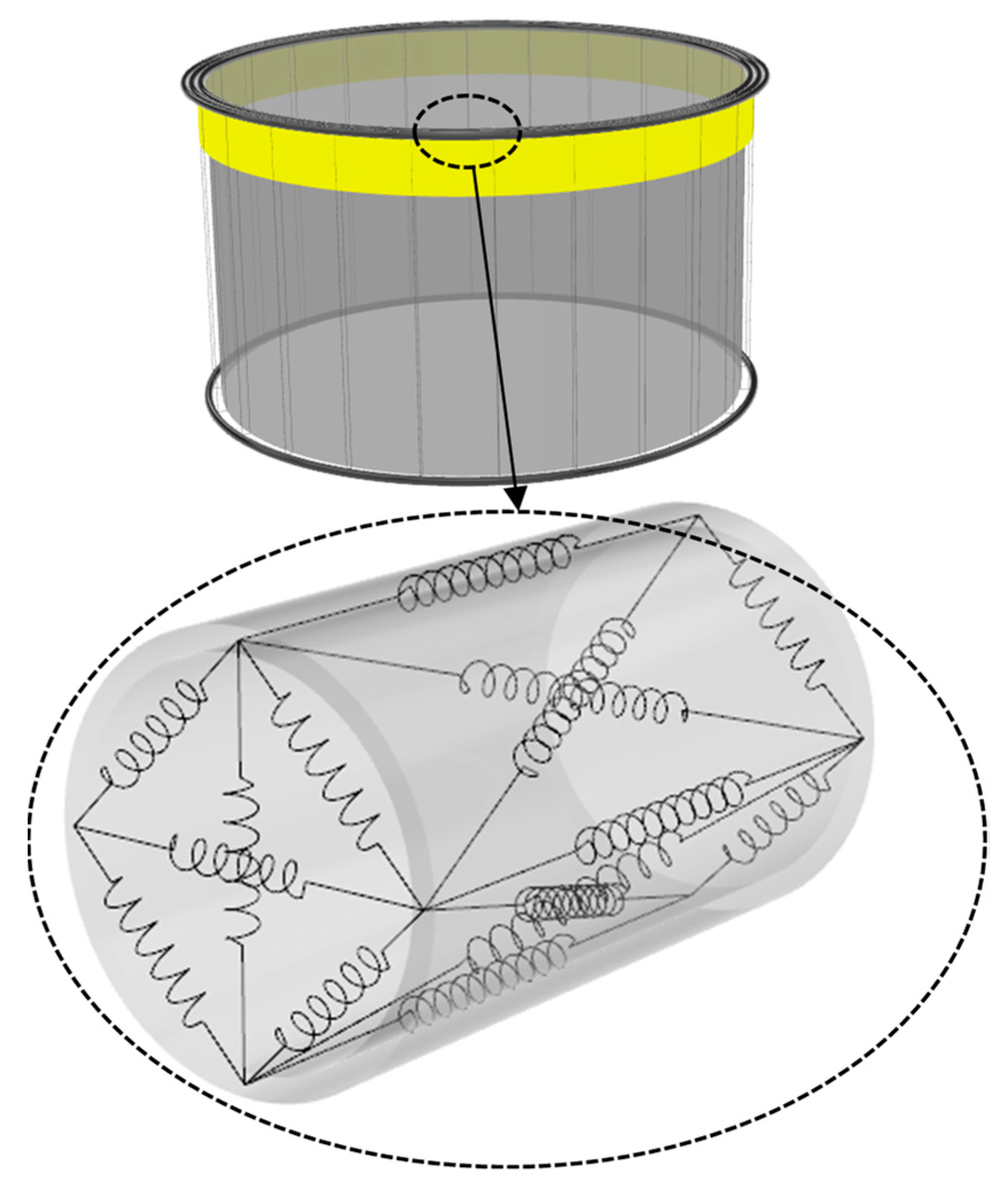
Rim modeling was performed following the methodology proposed by Lee et al. [13]. For analytical simplicity, the upper rim was simplified into three tubes without railings or platforms, whereas the lower rim was represented by a single tube. In this modeling approach, the rim is discretized into a finite number of cuboids along its circumference (Figure 4). Springs are arranged along the edges and diagonals of the cuboids to maintain their structural integrity under external forces from various directions. The projected area and weight assigned to each mass point within a cuboid were calculated by dividing the total rim values by the number of mass points. The shape of the cage net with and without an egg collection net was compared by assuming that the upper rim remained fixed in its initial position.

2.2. Modeling Method for Net-to-Net Interaction

In this study, the interaction between two net panels was modeled using the penalty method [17,18]. The penalty method, based on Newton’s third law of motion, introduces a repulsive force to prevent interpenetration when two objects come into contact. Upon contact, the energy of the system increases, prompting a natural evolution toward a state that minimizes this energy. This process generates a repulsive response that reduces overlap between the objects. The potential energy function representing the repulsive interaction between contacting objects is defined as follows:
π p = 1 2 δ T α δ ,
where α represents the penalty or contact stiffness, which characterizes the repulsive behavior during contact between two objects [18]. This can be computed as follows:
α = 4 3 σ R i R j R i + R j ,
where R denotes the radius of the twine cross-section [18] and σ is further derived as follows:
σ = 1 ν i 2 E i + 1 ν j 2 E j ,
where E represents the Young’s modulus, ν represents the Poisson’s ratio, and i and j represent the indices of the contacting objects.
In Equation (11), δ represents the penetration function, which quantifies the degree of interpenetration between the contacting objects. The repulsive force is obtained by differentiating the potential energy function in Equation (11) with respect to δ , as follows:
f p = α δ ,
The penetration function δ is a function of the displacement of the points and can be approximated through a Taylor series expansion, neglecting higher-order terms, as follows:
δ u = δ 0 + δ u u = δ 0 + Q { u } ,
where δ 0 represents the initial penetration depth between the contacting objects and Q represents the sensitivity matrix (the Jacobian matrix of the penetration function with respect to the displacements of the contacting objects).
The general form of the potential energy function for a mass–spring system under fluid forces is expressed as
Π = 1 2 u T K u u T F .
By incorporating the contact potential function defined in Equation (15), the total potential energy function becomes
Π = 1 2 u T K u u T F + 1 2 δ T α δ ,
where K represents the stiffness matrix of the springs acting on each point in the system, {u} represents the matrix for the displacement of the point, and F represents the external forces acting on the system. By substituting the penetration function defined in Equation (15) into Equation (17), the complete form of the total potential energy function is expressed as follows:
Π = 1 2 u T K u u T F + 1 2 ( δ 0 + Q u ) T α ( δ 0 + Q u ) .
In a physical system characterized by a potential energy function, equilibrium is achieved when the potential energy reaches its minimum value. This condition corresponds to a case in which the derivative of the potential function is zero. Therefore, differentiating Equation (18) with respect to u yields
Π u = K + Q T α Q { u } F + Q T α δ 0 .
By solving Equation (19) with respect to u, the physical displacement of the mass points undergoing contact-induced repulsion can be calculated.

2.3. Estimation of Volume Reduction in the Cage Net

The volume change in the cage net under the influence of current flow was calculated by the approach suggested by Huang et al. [19]. The cylindrical fish cage was discretized into M vertical layers and N radial slices. Each segment was further subdivided into three tetrahedra. For each tetrahedron, one vertex was designated as the origin, and vector A, B, C were defined along the three adjacent edges. The volume of an individual tetrahedron was approximated using the scalar triple product, as shown in Equation (20):
V n = 1 6 A · B × C
By summing the volumes of all tetrahedra, an approximate total volume of the cage net was obtained.

2.4. Simulation Conditions

Current was modeled to flow from west to east, corresponding to left-to-right movement across the computational domain. Flow velocities were maintained consistent between scenarios: one with only the cage net and another with an additional egg collection net. The simulated current speeds were 0.2, 0.3, 0.4, 0.5, and 0.6 m/s.
Weights (iron sinkers) were attached to the lower edge of the egg collection net at 1 m intervals along its perimeter. The underwater weight of each sinker was set at 0, 19.6, 39.2, 58.9, and 78.5 N, where 0 N represents the condition with no attached weight.

3. Results and Discussion

3.1. Behavior of the Net Cage and Egg Collection Net Under Various Current Speeds

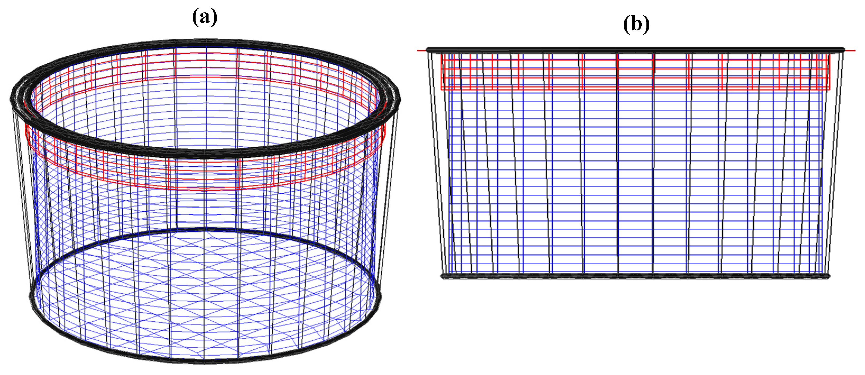
The initial configuration of the net cage, including the attached egg collection net, is shown in Figure 5. For clarity, the net cage is shown in blue, egg collection net in red, and rim and ropes in black.
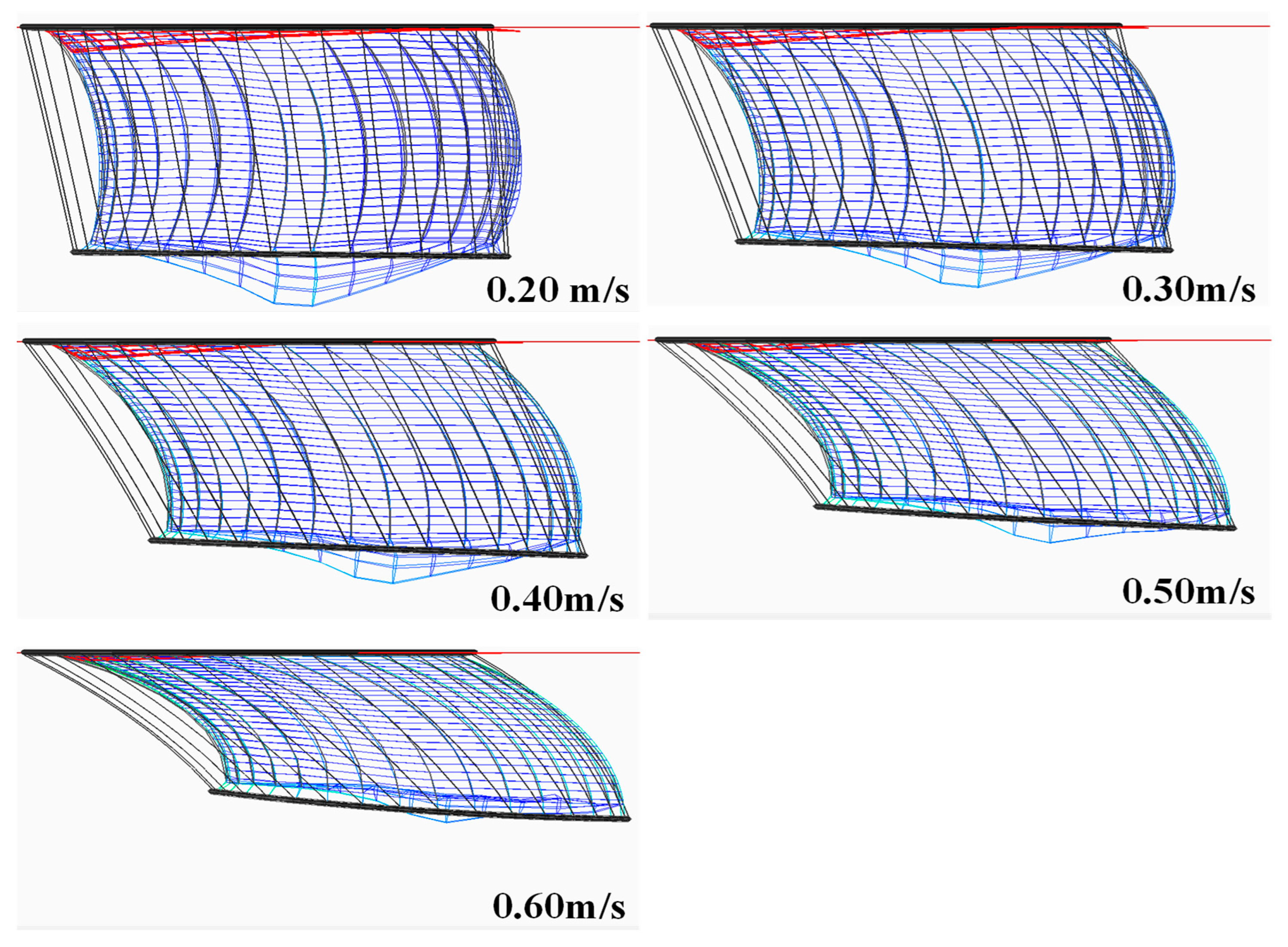
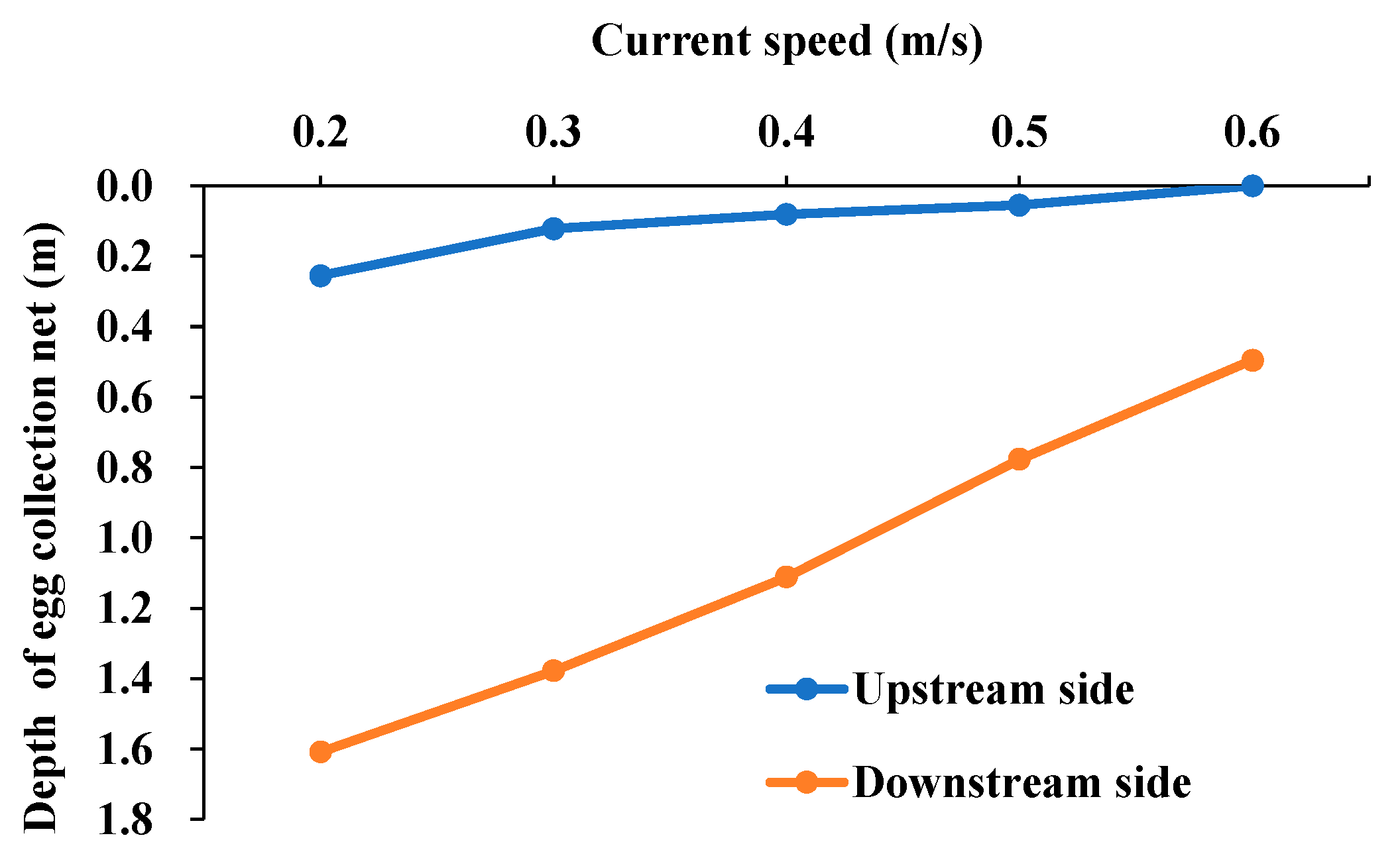
When current was applied to the cage system with the egg collection net, both the cage and egg collection nets on the upstream (left) side overlapped and were deflected downstream (to the right), as shown in Figure 6. The degree of deflection increased proportionally with current speed. As shown in Figure 7, the depth of the lower end of the egg collection net on the downstream (right) side decreased linearly with increasing current speed, reaching a shallow depth of just 0.26 m even at the lowest current speed (0.2 m/s). On the upstream (left) side, the egg collection net initially maintained a greater depth of 1.61 m at a low current speed (0.2 m/s); however, as the current increased, the upper portion of the net was pushed upward toward the water surface, resulting in a shallower bottom depth, as shown in Figure 7. These findings suggest that, under these conditions, collecting eggs from cultured fish would be challenging, regardless of the current speed.

3.2. Behavior of the Egg Collection Net Based on Sinker Weight

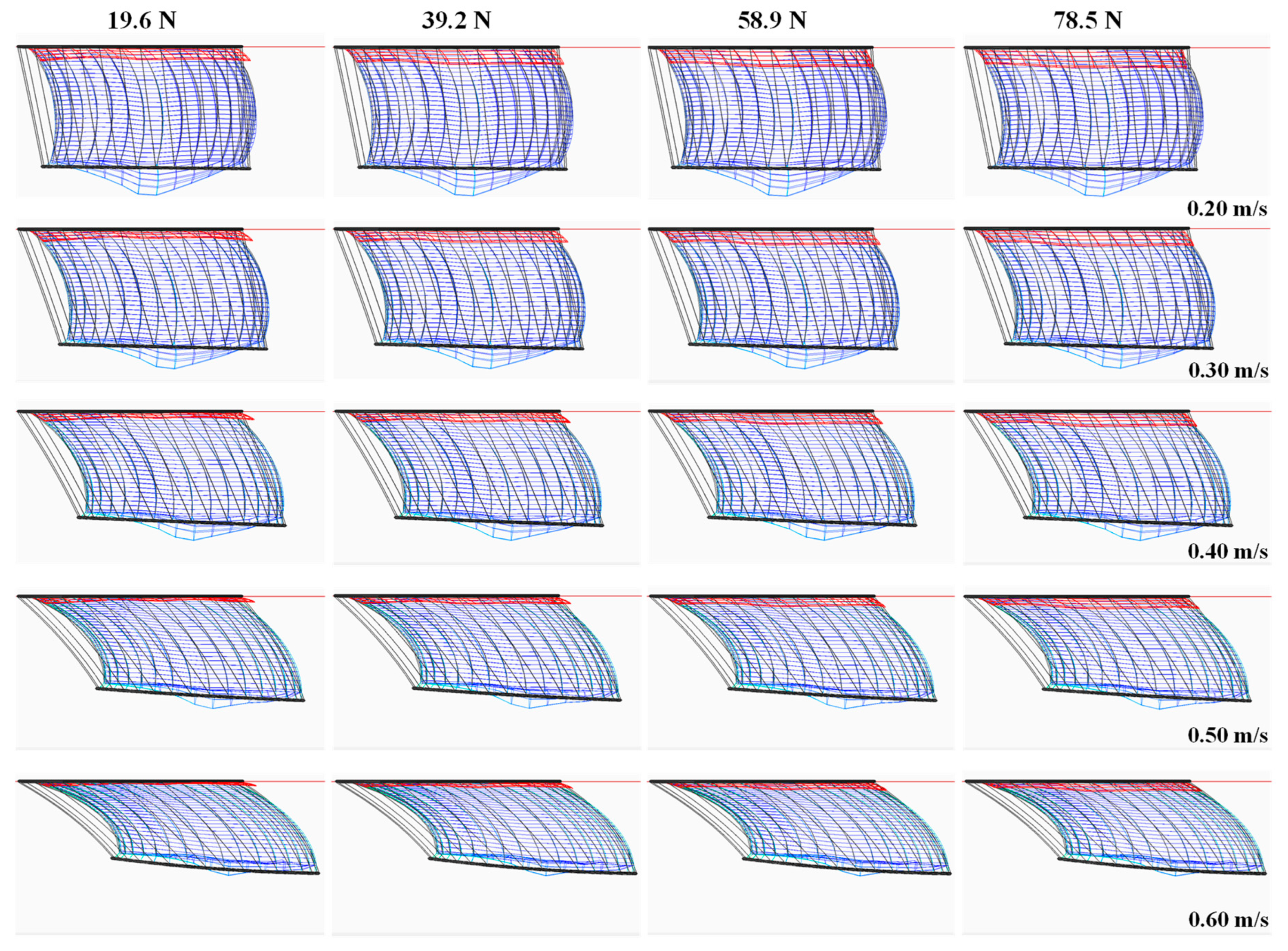
The behavior of the egg collection net with attached sinkers under various current speeds is shown in Figure 8. Each row represents a different current speed, whereas each column corresponds to a different sinker weight. As the speed of the current increased, the cage net experienced increased deflection in the downstream direction and upward displacement at its bottom. However, variations in sinker weight had minimal impact on the overall shape of the cage net. In contrast, for the egg collection net, increasing the sinker weight reduced the upward deflection at the downstream end, whereas the upstream end remained largely unchanged.
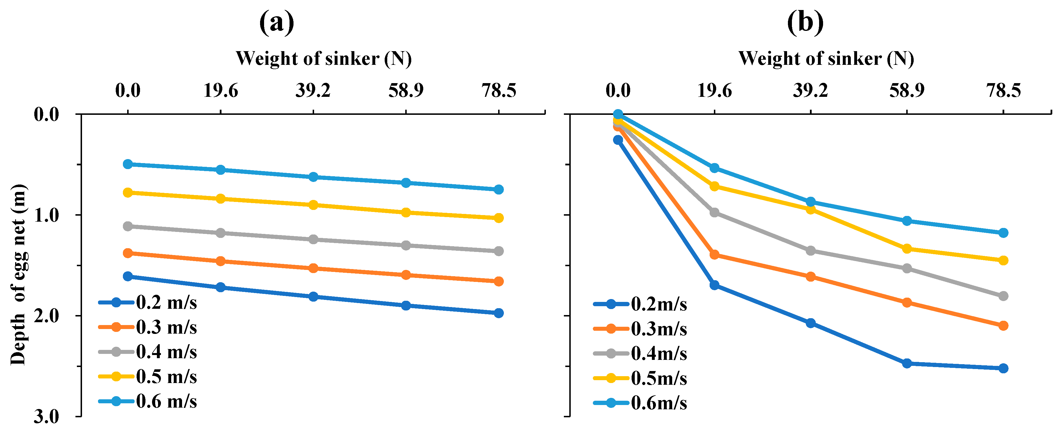
To quantitatively evaluate the shape variation in the egg collection net owing to the sinker weight and current speed, we investigated the depth variations at the bottom of the egg collection net located at the upstream and downstream ends of the cage. The results indicate that, at the upstream end, the bottom depth of the egg collection net increased linearly with increasing sinker weight (Figure 9a) and decreased linearly as the current speed increased (Figure 10a). For the downstream egg collection nets, the bottom depth increased logarithmically with increasing sinker weight (Figure 9b) and decreased linearly with increasing current speed (Figure 10b).
In Figure 10b, the dashed line (indicated by the legend “Main net only”) represents the depth variation in a point in the cage net that initially corresponded to the bottom of the egg collection net before the current application (initial depth: 2.6 m). This reference depth served as a threshold for determining the optimal sinker weight. As shown in Figure 10b, the appropriate sinker weight for minimizing the deflection of the downstream net was estimated at 78.5 N/m.
Furthermore, as shown in Figure 9 and Figure 10, the downstream egg collection net was more sensitive to changes in sinker weight than the upstream net. This heightened sensitivity can be attributed to the net configuration: on the upstream side, the egg collection net was positioned behind and constrained by the cage net. In contrast, on the downstream side, the egg collection net was situated in front of the cage net and subjected to greater hydrodynamic resistance owing to its finer mesh, which enables more independent motion.

3.3. Impact of Egg Collection Net Installation on Cage Net Volume

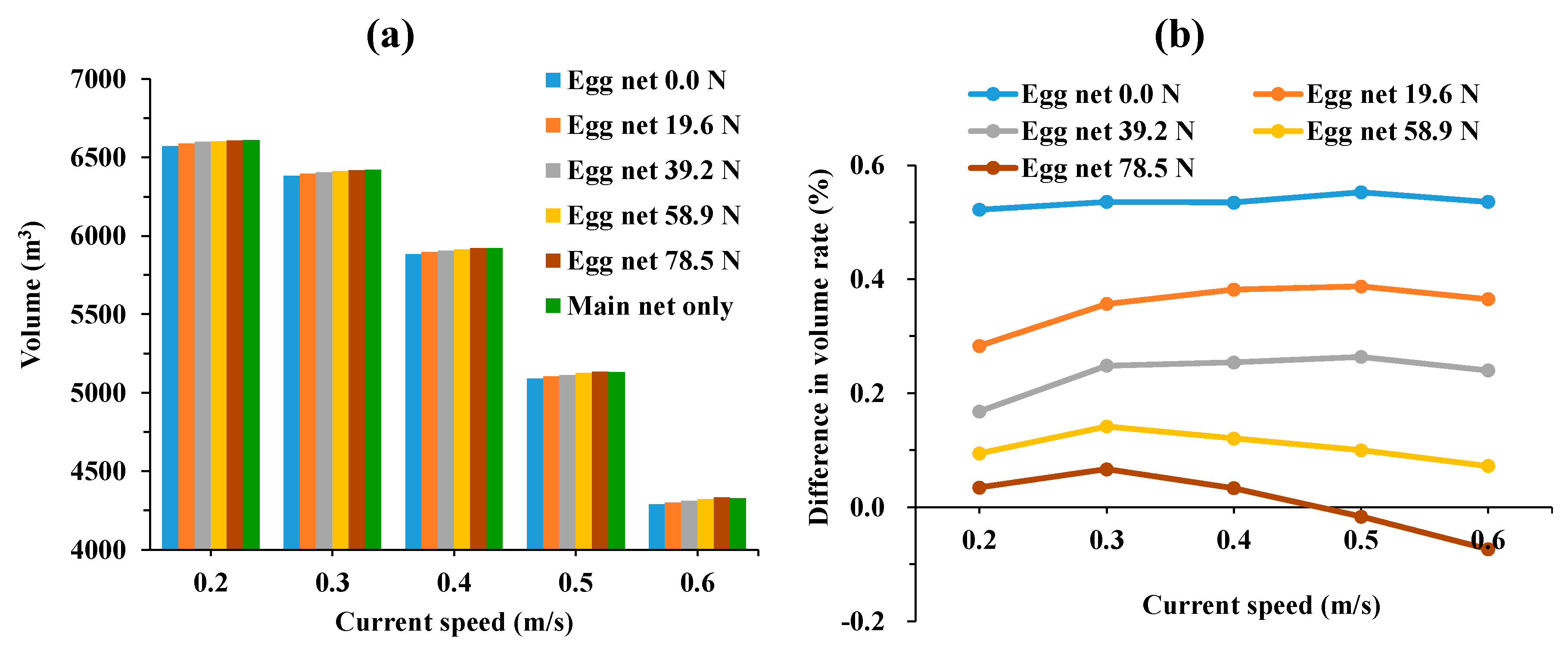
The volume of the cage net was generally lower when the egg collection net was installed, compared with when it was absent (Figure 11a), across most current speeds and sinker weights; however, the difference was minimal. Regarding the sinker weights attached to the bottom of the egg collection net, the cage net volume increased with increasing sinker weight, a pattern that was consistently observed across all current speeds. To evaluate the impact of the egg collection net on cage net volume, the ratio of the cage net volume after the current application to its initial volume (7363.1 m3) was calculated for scenarios with and without the egg collection net. The difference in the volume ratios obtained by subtracting the ratio with the egg collection net from the ratio without it is shown in Figure 11b. The results indicated that this difference in volume ratios decreased as sinker weight increased, regardless of the current speed. Furthermore, the difference followed a quadratic trend with a negative slope: it initially increased and then decreased as the current speed increased. This trend was consistent across all sinker weights, with the inflection point of the quadratic function occurring at lower current speeds for heavier sinker weights. For example, with the heaviest sinker weight of 78.5 N, the inflection point occurred at 0.3 m/s. At flow velocities above 0.5 m/s, the volume ratio difference became negative. A negative difference indicated that the net cage volume with the egg collection net installed exceeded that without the net. Thus, although the installation of an egg collection net generally reduces the net cage volume, the volume may increase under specific conditions.
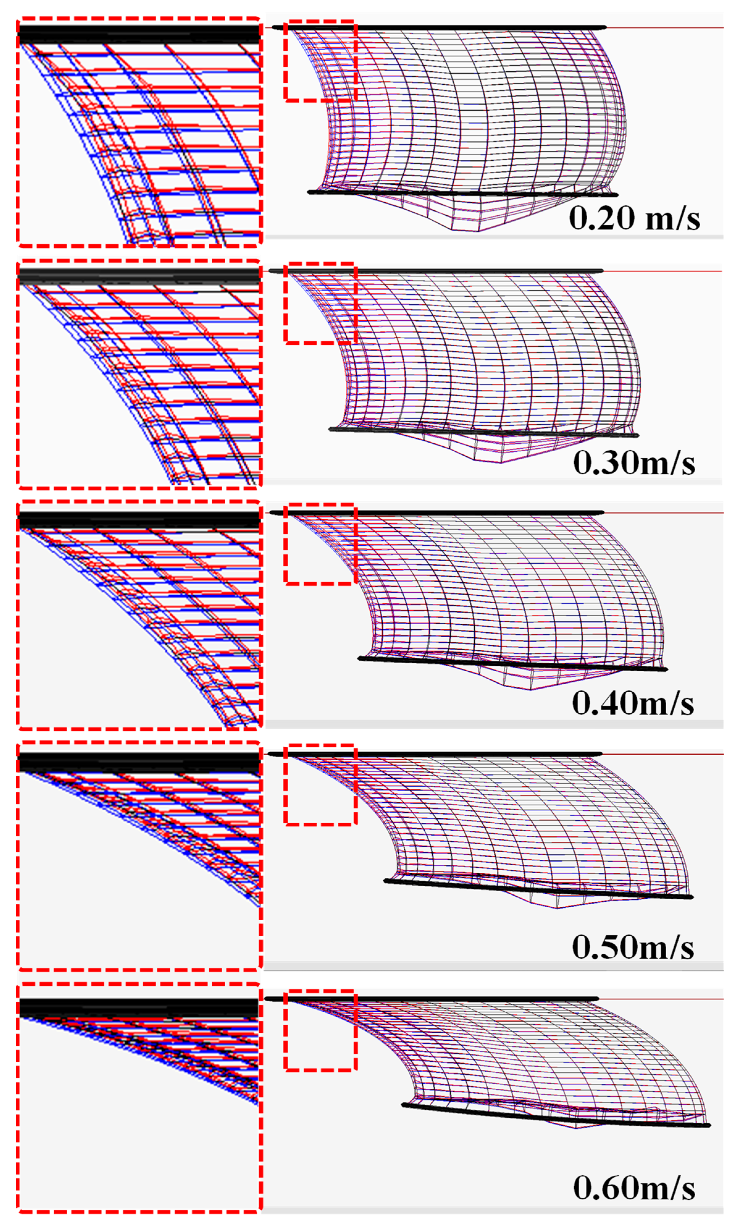
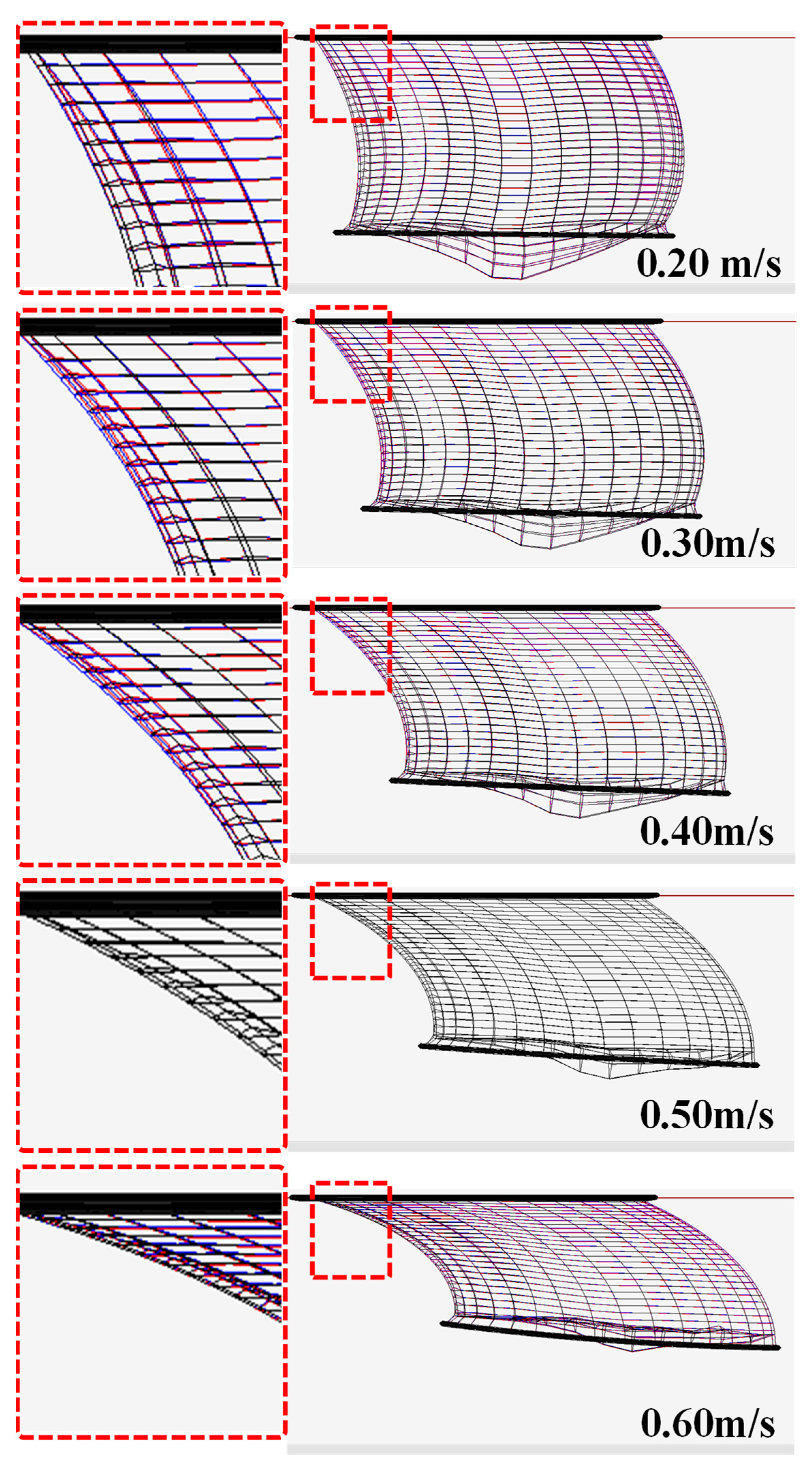
Increasing the sinker weight attached to the egg collection net resulted in a larger cage volume, suggesting that heavier sinkers helped minimize cage deformation caused by the net. The deformation of the cage net primarily occurred on the upstream side, where the current entered, resulting in greater displacement of the egg collection net and, consequently, increased cage deformation. However, the sinker weight, acting primarily downward owing to gravity, counteracted the upward and downstream forces exerted by the current on the bottom of the egg collection net. This action effectively reduced the deformation of the cage net. The mitigating effect was validated by comparing the displacement differences in the cage net with and without the egg collection net under varying sinker weight conditions, as shown in Figure 12 and Figure 13 (the egg collection net is omitted in these figures). Figure 12, which represents the scenario with the lightest sinker weight of 19.6 N, demonstrates that the presence of the egg collection net resulted in a significantly greater downstream displacement compared with the case without it. Conversely, Figure 13, which represents the scenario with the heaviest sinker weight (78.5 N), reveals that the displacement difference is negligible, with minimal distinction between the two cases.
The difference in volume ratio (ranging from 0.01% to 0.54%), obtained from simulations comparing configurations with and without the egg collection net, quantified the additional volumetric reduction caused by its installation. This metric serves as an indicator of the extent to which the egg collection net contributes to the deformation of the cage structure. This metric serves as an indicator of the extent to which the egg collection net contributes to the deformation of the cage structure.
To evaluate the significance of this volume ratio, we referenced current speed data collected at Tongyeong Port using an oceanographic buoy, the closest monitoring station to the cage installation site. The data, recorded from 1 July to 31 July 2021, included the actual deployment period of the egg collection net. The 10 min interval current speed distribution during this period is shown in Figure 14 [20].
The mean current speed calculated from these data was 0.203 m/s, with a standard deviation of 0.218 m/s. In this study, we assumed that speed variations within one standard deviation of the mean fell within the range of natural variability. Accordingly, we analyzed the variation in cage volume ratio. The relationship between the current speed and cage volume ratio was derived from the simulation results and is expressed using Equation (21) as follows:
V s =   147.921407 x 2   +   38.843447 x   +   88.269740 .
We conducted the Anderson–Darling test to evaluate the normality of the current speed distribution. The results indicated that the distribution deviated significantly from normality (A = 369.88, p < 0.05). Consequently, rather than relying on traditional parametric statistics based on the mean and standard deviation, we adopted a non-parametric, quantile-based approach. Specifically, the median of the current speed distribution was adopted as the reference speed, whereas the interquartile range (IQR) and median absolute deviation (MAD) were used as measures of variability [21]. This method was considered robust as it accurately reflected the most frequently occurring hydrodynamic conditions without assuming normality.
The cage volume ratios corresponding to the median, IQR and MAD speeds are calculated using Equation (21). As a result, the median speed was 0.128 m/s, with a corresponding cage volume ratio of 90.82%. The upper quartile speed (Q3) was 0.291 m/s, and its associated volume ratio was 86.61%. Furthermore, within the median ± MAD range (0.128 ± 0.144 m/s, i.e., up to 0.272 m/s), the volume ratio was 87.89%. Accordingly, an increase in current speed from 0.128 m/s to 0.291 m/s resulted in a 4.21% decrease in the cage volume ratio, whereas an increase to 0.272 m/s (median + MAD) led to a 2.93% decrease. This reduction was significantly larger than the 0.01–0.54% reduction observed owing to the egg collection net installation. These findings indicate that the impact of net installation on volume reduction was negligible compared with the natural variability of the current speed.
In this study, the implications of volume changes caused by the egg collection net were analyzed; however, these results alone are insufficient to conclude that such changes have negligible effects on Pacific bluefin tuna. Therefore, future research should investigate how net-induced volume reductions influence the behavior, growth, and survival of bluefin tuna. In addition, it will be necessary to examine biological factors, such as the movement of tuna within the cage, which may interact with net deformation.
Numerous studies have investigated underwater shape or volume changes in cages under environmental forces, such as currents [19,22,23,24,25,26]. However, these studies focused solely on the interaction between the environment and cage itself, without considering the influence of additional structures attached to the cage. Furthermore, studies that address scenarios in which supplementary structures comprise flexible, mesh-like materials that physically interact with existing cage nets are limited. For example, although some studies [26] have addressed the behavior of double-layered cage nets under current conditions, these nets were separated by fixed frames, and physical contact was not considered. Other studies [22,23,24] have analyzed the hydrodynamic resistance experienced by multiple adjacent cages; however, the physical interactions between the nets were not considered. Therefore, this study provides a unique and valuable contribution by analyzing the effects of an egg collection net that directly interacts with the cage net through physical contact.
The accuracy of the penalty model used to simulate contact between two objects has been verified in relevant studies. For example, Cardiff et al. (2012) [27] and Zang et al. (2011) [28] modeled the surfaces of two potentially contacting objects as master and slave surfaces, generating repulsive forces proportional to the penetration when slave surface nodes penetrate the master surface. The validity of their approach was confirmed by comparing simulation results with analytical solutions. Furthermore, the accuracy of the mass–spring model for simulating cage behavior has also been validated through comparisons with tank experiments in prior studies [13,15]. However, these prior validations do not constitute direct verification of the contact between the egg collection net and cage net as presented in this study. We consider this point a limitation of our research. Future work should include validation of the model accuracy by comparing simulation results with physical experiments, such as tank tests.”
In still water, the lower edge of the egg collection net was initially positioned at a depth of 2.6 m. However, under flow conditions, this depth was significantly reduced. For example, at a current speed of 0.6 m/s, the lower edge depth was raised to just 1.18 m, even when optimally weighted sinkers were employed. In practical field conditions, sinkers are typically employed to exert an underwater weight of approximately 12.8 N per meter along the cage perimeter. Simulation results indicated that the lower edge of the net reached a depth of 0.533 m when the sinker weight was 19.6 N and remained at 0 m when no sinkers were applied. Based on this relationship, the estimated depth for a sinker weight of 12.8 N was approximately 0.348 m, representing only 14.4% of the original net height of 2.6 m. If the operators had been aware of and had anticipated these outcomes, operational issues would not be expected. However, if the net was expected to be deployed at a greater depth, egg collection efficiency would have been compromised. Sinker weights and egg collection net height specifications are typically determined empirically in field applications. This can result in suboptimal performance. A major limitation of this study is its reliance on empirical field values, which may limit the generalizability of the findings. To address these limitations, future research should investigate the behavior of egg collection nets under various design configurations (e.g., net material, mesh size, cage dimensions) and environmental conditions.

4. Conclusions

This study developed a mass–spring-based interaction model to simulate contact between the primary cage net and egg collection nets, and to examine the structural response and volume variation in a bluefin tuna cage under varying current conditions. The main findings are as follows:
  • Egg collection net behavior: The upstream egg collection net was displaced downstream, overlapping with the cage net, and the extent of deflection increased with current speed. The downstream egg collection net experienced pronounced uplift, with its lower edge approaching the water surface under low-flow conditions.
  • Effect of sinker weight: Additional sinker weight had negligible influence on the geometry of the cage net but effectively reduced uplift in the downstream egg collection net. The upstream egg collection net showed minimal sensitivity to weight.
  • Depth variation: The depth of the upstream egg collection net’s lower edge increased linearly with sinker weight and decreased linearly with current speed, while the downstream net exhibited logarithmic depth growth with weight and linear reduction with current. The optimal sinker weight to minimize egg collection net deflection was 78.5 N/m.
  • Cage volume impact: Cage volume reductions due to egg collection nets were minimal (0.01–0.54%) and decreased further as sinker weight increased from 0.0 to 78.5 N. Importantly, the overall shape of the cage net remained largely unaffected.
  • Volume ratio dynamics: The difference in volume ratio between cages with and without egg collection nets showed a quadratic relationship with current speed and consistently decreased with increasing sinker weight.
In summary, egg collection nets exert negligible effects on cage net geometry and total cage volume. The proposed model provides a framework for analyzing the mechanical behavior of double-layered net systems, improving the evaluation of cage stability and facilitating the assessment of potential tuna mortality. Future research should extend the model to diverse net configurations and environmental scenarios, with validation at full scale.

Author Contributions

Writing—original draft preparation, data managing, software, visualization, G.-H.L.; review and editing, conceptualization and methodology, I.K.; project administration and supervision, S.-C.J. All authors have read and agreed to the published version of the manuscript.

Funding

This research was funded by the National Institute of Fisheries Science, Ministry of Oceans and Fisheries, Korea (R2025022 and 2025030).

Data Availability Statement

Data are contained within the article.

Conflicts of Interest

The authors declare no conflicts of interest.

References

  1. Masuma, S.; Takebe, T.; Sakakura, Y. A review of the broodstock management and larviculture of the Pacific northern bluefin tuna in Japan. Aquaculture 2011, 315, 2–8. [Google Scholar] [CrossRef]
  2. Shin, A.; Yoon, S.C.; Lee, S.I.; Park, H.W.; Kim, S. The relationship between fishing characteristics of Pacific bluefin tuna (Thunnus orientalis) and ocean conditions around Jeju Island. Fish Aquat. Sci. 2018, 21, 1. [Google Scholar] [CrossRef]
  3. Kim, J.-G.; Kim, J.-G. Changes in Climate Factors and Catches of Fisheries in the Republic of Korea over the Three Decades. Water 2023, 15, 1952. [Google Scholar] [CrossRef]
  4. Park, J.-W.; Kim, J.-H.; JI, S.C.; Ryu, Y.-W.; Cho, J.-H. The reproductive potential of Pacific bluefin tuna (Thunnus orientalis) farmed in sea cages in South Korea. J. World Aquac. Soc. 2023, 54, 1497–1512. [Google Scholar] [CrossRef]
  5. De La Gandara, F.; Mylonas, C.; Coves, D.; Ortega, A.; Bridges, C.R.; Belmonte, R.A.; Vassallo-Agius, R.; Papandroulakis, N.; Rosenfeld, H.; Tandler, A.; et al. Seedling production of Atlantic bluefin tuna (ABFT) Thunnus thynnus. The selfdott project. In Proceedings of the Joint International Symposium of Kinki University and Setouchi Town on the 40th Anniversary of Pacific Bluefin Tuna Aquaculture, Towards the Sustainable Aquaculture of Bluefin Tuna, Amami, Japan, 15–16 October 2010; pp. 69–73. [Google Scholar]
  6. De Metrio, G.; Bridges, C.R.; Mylonas, C.C.; Caggiano, M.; Deflorio, M.; Santamaria, N.; Zupa, R.; Pousis, C.; Vassallo-Agius, R.; Gordin, H.; et al. Spawning induction and large-scale collection of fertilized eggs in captive Atlantic bluefin tuna (Thunnus thynnus L.) and the first larval rearing efforts. J. Appl. Ichthyol. 2010, 26, 596–599. [Google Scholar] [CrossRef]
  7. Bi, C.-W.; Zhao, Y.-P.; Dong, G.-H.; Zheng, Y.-N.; Gui, F.-K. A numerical analysis on the hydrodynamic characteristics of net cages using coupled fluid–structure interaction model. Aquac. Eng. 2014, 59, 1–12. [Google Scholar] [CrossRef]
  8. Li, L.; Fu, S.; Xu, Y.; Wang, J.; Yang, J. Dynamic responses of floating fish cage in waves and current. Ocean Eng. 2013, 72, 297–303. [Google Scholar] [CrossRef]
  9. Zhao, Y.; Guan, C.; Bi, C.; Liu, H.; Cui, Y. Experimental investigations on hydrodynamic responses of a semi-submersible offshore fish farm in waves. J. Mar. Sci. Eng. 2019, 7, 238. [Google Scholar] [CrossRef]
  10. Chen, H. Modelling of Floating Fish Cage Dynamics with Computational Fluid Dynamics. Ph.D. Thesis, Technical University of Denmark, Kongens Lyngby, Denmark, 23 December 2016. Available online: https://orbit.dtu.dk/files/162637176/Thesis_HaoChen_002_pdf (accessed on 19 July 2025).
  11. Shainee, M.; DeCew, J.; Leira, B.J.; Ellingsen, H.; Fredheim, A. Numerical simulation of a self-submersible SPM cage system in regular waves with following currents. Aquac. Eng. 2013, 54, 29–37. [Google Scholar] [CrossRef]
  12. Cha, B.J.; Lee, C.W.; Lee, J.H.; Kim, H.Y. Hydrodynamic simulation of midwater trawl system behavior. J. Korean Soc. Fish. Ocean Technol. 2002, 38, 164–171. [Google Scholar]
  13. Lee, C.W.; Kim, Y.B.; Lee, G.H.; Choe, M.Y.; Lee, M.K.; Koo, K.Y. Dynamic simulation of a fish cage system subjected to currents and waves. Ocean Eng. 2008, 35, 1521–1532. [Google Scholar] [CrossRef]
  14. Lee, G.H.; Cha, B.J.; Kim, H.Y. A study on the minimization of mooring load in fish-cage mooring systems with a damping buoy. J. Mar. Sci. Eng. 2020, 8, 814. [Google Scholar] [CrossRef]
  15. Lee, M.K.; Lee, C.W. Dynamic analysis of a cage affected by the current. J. Korean Soc. Fish Ocean Technol. 2004, 40, 214–224. [Google Scholar]
  16. Kim, T.H. Design of Fish Aquaculture Cage; Jeonnam University: Yeosu, Republic of Korea, 2009; pp. 98–99. [Google Scholar]
  17. Shi, Y. A New Penalty Stiffness Treatment for Master-Slave Contact Surfaces. Master’s Thesis, McMaster University, Hamilton, ON, Canada, September 2001. Available online: https://macsphere.mcmaster.ca/bitstream/11375/25261/1/shi_yihai_2001Sep_masters.pdf (accessed on 16 April 2025).
  18. Corral, E.; Moreno, R.G.; García, M.J.G.; González, M.I. Nonlinear phenomena of contact in multibody systems dynamics: A review. Nonlinear Dyn. 2021, 104, 1269–1295. [Google Scholar] [CrossRef]
  19. Huang, C.-C.; Tang, H.-J.; Liu, J.-Y. Dynamical analysis of net cage structures for marine aquaculture: Numerical simulation and model testing. Aquac. Eng. 2006, 35, 258–270. [Google Scholar] [CrossRef]
  20. Korea Hydrographic and Oceanographic Agency. Available online: https://www.khoa.go.kr/oceangrid/gis/category/reference/distribution.do (accessed on 15 February 2025).
  21. Rousseeuw, P.J.; Croux, C. Alternatives to the Median Absolute Deviation. J. Am. Stat. Assoc. 1993, 88, 1273–1283. [Google Scholar] [CrossRef]
  22. Hu, Y.; Zhao, H.; Shi, W.; Bi, C.; Li, X. Numerical Study on Internal and External Flow Fields of the UHMWPE Cage. J. Mar. Sci. Eng. 2023, 11, 1881. [Google Scholar] [CrossRef]
  23. Xu, T.-J.; Dong, G.-H.; Zhao, Y.-P.; Li, Y.-C.; Gui, F.-K. Numerical investigation of the hydrodynamic behaviors of multiple net cages in waves. Aquac. Eng. 2012, 48, 6–18. [Google Scholar] [CrossRef]
  24. Zhao, Y.-P.; Bi, C.-W.; Chen, C.-P.; Li, Y.-C.; Dong, G.-H. Experimental study on flow velocity and mooring loads for multiple net cages in steady current. Aquac. Eng. 2015, 67, 24–31. [Google Scholar] [CrossRef]
  25. Liu, Z.; Soares, C.G. Uncertainty Assessment of the Remaining Volume of an Offshore Gravity Fish Cage. J. Mar. Sci. Eng. 2024, 12, 289. [Google Scholar] [CrossRef]
  26. Ji, J.; Zhou, L.; Liu, B.; Soares, C.G. Experimental and numerical study on the flow field of a bottom-supported net cage with double-layer fishing nets. Ocean Eng. 2025, 319, 120228. [Google Scholar] [CrossRef]
  27. Cardiff, P.; Karač, A.; Ivanković, A. Development of a finite volume contact solver based on the penalty method. Comput. Mater. Sci. 2012, 64, 283–284. [Google Scholar] [CrossRef]
  28. Zang, M.; Gao, W.; Lei, Z. A contact algorithm for 3D discrete and finite element contact problems based on penalty function method. Comput. Mech. 2011, 48, 541–550. [Google Scholar] [CrossRef]
Figure 1. Schematic of a fish cage including the attached egg collection net for numerical modeling.
Jmse 13 01762 g001
Figure 2. Cage net represented by a mass–spring system and mesh grouping.
Jmse 13 01762 g002
Figure 3. Schematic of the force vectors acting on a mass point.
Jmse 13 01762 g003
Figure 4. Schematic of the cage rim modeling method.
Jmse 13 01762 g004
Figure 5. Initial configuration of the net cage with the egg collection net attached: (a) three-dimensional view and (b) side view. The red color indicates the egg collection net, while the blue color represents the main net cage.
Jmse 13 01762 g005
Figure 6. Underwater shapes of the net cage and egg collection net at various current speeds. The red color indicates the egg collection net, while the blue color represents the main net cage.
Jmse 13 01762 g006
Figure 7. Depth of the egg collection net bottom under different current speeds.
Jmse 13 01762 g007
Figure 8. Underwater shape of the egg collection net under various sinker weights and current speeds. The red color indicates the egg collection net, while the blue color represents the main net cage.
Jmse 13 01762 g008
Figure 9. Bottom depth of the egg collection net as a function of sinker weight: (a) upstream side and (b) downstream side.
Jmse 13 01762 g009
Figure 10. Bottom depth of the egg collection net as a function of current speed: (a) upstream side and (b) downstream side.
Jmse 13 01762 g010
Figure 11. Volume of the cage net (a) and the difference in volume ratios (b) between the cage and egg collection nets as functions of current speed and sinker weight at the bottom of the egg collection net.
Jmse 13 01762 g011
Figure 12. Comparison of the underwater (superimposed) configurations of the cage net (blue net) and cage net with the egg collection net installed (red net) at various flow velocities, with a sinker weight of 19.6 N (egg collection net omitted).
Jmse 13 01762 g012
Figure 13. Comparison of the underwater (superimposed) configurations of the cage net (blue net) and cage net with the egg collection net installed (red net) at various flow velocities, with a sinker weight of 78.5 N (egg collection net omitted).
Jmse 13 01762 g013
Figure 14. Ten-minute interval current speed distribution at Tongyeong Port from 1 July to 31 July 2021 (data source: South Korea Hydrographic and Oceanographic Agency [20]).
Jmse 13 01762 g014
Table 1. Specifications of the cage for numerical modeling.
ParameterSizeMaterial Properties
Upper rim
Inner rim⌀400 mm, dia. 25.4 m, 22.5 THDPE
Middle rim⌀400 mm, dia. 26.5 m, 22.5 THDPE
Outer rim⌀315 mm, dia. 27.6 m, 18.0 THDPE
Lower rim⌀50 mm, dia. 26.0 m, W a 18,482 NSteel
Side rope⌀30 mm × 24 linePE
Lacing rope⌀24 mm × 24 linePE
Sinker245.3 N × 2 eaIron
Body net⌀4 mm, mesh size 35.35 mmPE (SG b = 0.94)
dia. 25.0 m, height 15.0 m
Solidity ratio 0.2135
Egg collection net⌀353 µm, mesh size 818 µmPET (SG b = 1.47)
dia. 25.8 m, height 2.6 m
Solidity ratio 0.6768
a: Weight in sea water, b: Specific gravity.
Disclaimer/Publisher’s Note: The statements, opinions and data contained in all publications are solely those of the individual author(s) and contributor(s) and not of MDPI and/or the editor(s). MDPI and/or the editor(s) disclaim responsibility for any injury to people or property resulting from any ideas, methods, instructions or products referred to in the content.