Article

Power Estimation Method and Its Validation for Ships with Hybrid Contra Rotating Propeller

by
Tomoki Wakabayashi
1,* and
Tokihiro Katsui
2
1
Technical Research Center, Japan Marine United Corporation, Tsu 514-0398, Japan
2
Ocean-Bottom Exploration Center, Kobe University, Kobe 658-0022, Japan
*
Author to whom correspondence should be addressed.
J. Mar. Sci. Eng. 2025, 13(9), 1740; https://doi.org/10.3390/jmse13091740
Submission received: 19 August 2025 / Revised: 6 September 2025 / Accepted: 9 September 2025 / Published: 10 September 2025
(This article belongs to the Section Ocean Engineering)

Abstract

In response to the urgent need for reducing greenhouse gas emissions, the Hybrid Contra Rotating Propeller (HCRP) system, which combines a main engine-driven propeller with an electrically driven Podded propeller, has become a promising propulsion system for CO2 reduction. This paper presents a new power estimation method for ships with HCRP and outlines the required model test procedures. This study proposes a power estimation method tailored for ships equipped with HCRP and outlines towing tank test procedures required for validation. The method separately evaluates open water characteristics of each propeller and accounts for interactions between the propellers, pod, and hull. Sea trials on an actual vessel were conducted, including speed trials at constant rotational speed ratios and variation tests. These trials confirmed the method’s ability to predict propulsion performance across a wide range of ship speeds. The estimated error in total output from the main engine and generator was within 5% at low output and more accurate near the design speed for the tested case. Furthermore, the method accurately estimates the relationship between rotational speed ratio and power distribution between the main engine and generator for the pod motor, demonstrating its effectiveness for performance prediction and design optimization of HCRP-equipped vessels.

1. Introduction

In recent years, the reduction of greenhouse gas (GHG) emissions has become an urgent issue in the international shipping industry. In 2023, the International Maritime Organization (IMO) adopted the “2023 GHG Reduction Strategy,” setting a goal to achieve net-zero GHG emissions from international shipping by 2050 [1]. This strategy includes the promotion of zero-emission fuels and the introduction of carbon pricing systems, strongly encouraging technological innovation in ship propulsion systems. Soltani Motlagh et al. investigated decarbonization strategies in container shipping and reported that operational optimization (e.g., slow steaming), technological approaches such as optimized ship design, and the adoption of alternative fuels are effective in reducing CO2 emissions [2]. Furthermore, Issa-Zadeh et al. reported that pilotage operations at ports contribute to CO2 reduction [3]. This finding suggests that improvements in a vessel’s low-speed maneuverability can be associated with enhanced environmental performance and contribute to emission reduction efforts. In Japan, research and development of next-generation vessels aiming to balance environmental sustainability and economic efficiency is progressing through initiatives such as the “Super Eco Ship Project” led by the Ministry of Land, Infrastructure, Transport and Tourism. [4]
A propulsion system known as the Hybrid Contra-Rotating Propeller (HCRP) is being developed, characterized by its use of two propellers: a controllable pitch propeller (CPP) driven by a diesel engine, and an azimuth-type pod propeller driven by an electric motor. These two propellers are aligned on the same axis and rotate in opposite directions, forming a contra-rotating propeller (CRP) configuration. HCRP combines the characteristics of both CRP propulsion and POD propulsion systems [5].
CRP was first adopted in an actual vessel by Mitsubishi Heavy Industries in 1989, and a significant improvement in propulsion performance was demonstrated in practice [6]. Although there are difficulties with respect to construction, such as the need for installing special bearings, many ships have adopted this system [4,7]. On the other hand, Mevis highlighted several benefits of POD propulsion in his study, such as enhanced maneuvering capabilities, greater cargo space enabled by adaptable engine room arrangements, and diminished vibration levels [8]. These features have led to its widespread adoption in modern vessels.
In 2014, HCRP was first applied to a ROPAX ferry by Mitsubishi Heavy Industries, resulting in a 13% improvement in propulsion efficiency compared to twin-shaft vessels [9]. As in this case, if the original ship is twin-shaft propulsion, changing to HCRP allows hull appendages such as shaft brackets to be removed, resulting in a significant improvement in propulsion efficiency due to reduced resistance. After the first application of HCRP, some coastal vessels have adopted HCRP. The HCRP system has advantages in maneuverability at low speeds, making it suitable for coastal ships that frequently perform berthing operations. Furthermore, applications to general commercial ships such as bulk carriers, tankers, and container ships are also expected. The EU’s TRIPOD project has summarized towing tank test methods and CFD-based performance estimation methods. Additionally, the project evaluated the economic feasibility for cargo transport vessels [10,11,12].
To design high-performance ships, it is essential to accurately estimate the propulsion performance of ships in full-scale. Performance estimation is practically based on the scaled model test, with applying scale corrections to full-scale. The testing procedure and its results for the coaxial CRP system were summarized by Manen [13]. Various power estimation techniques were tested by Inukai et al., and their accuracy was assessed through comparison with speed trial data from actual ships equipped with CRP [14]. The tank test method for POD is introduced by Mewis [8] and standardized as ITTC RP [15].
Sasaki et al. [16] formulated tank testing procedures for HCRP systems, based on the assumption that the net force produced by the twin propellers could be represented as that of a single propeller for analytical purposes. Chang et al. [17] conducted a series of tank tests to investigate the influence of propeller rotational speed on the power ratio. The testing procedures they introduced were formalized in the ITTC RP [18]. The power estimation method recommended in ITTC RP is applicable only for the specific rotational speed ratio of two propellers, because it treats the combined force of two propellers acting as CRP in specific rotational speed ratio.
The objective of this study is to establish a power estimation method capable of accurately predicting ship’s performance at arbitrary rotational speed ratios of two propellers, along with the towing tank test procedures required for its application. Accurately evaluating the dependency on the rotational speed ratio enables optimal ship design that accounts for this unique feature of HCRP, thereby contributing to further reductions in CO2 emissions.
Wakabayashi et al. have proposed a new open water test method for HCRP [19]. Due to the unusual equipment arrangement required for the propeller open water test for HCRP, the propellers must be tested in a flow field disturbed by the propeller open boat. Their method effectively eliminates the effect from these disturbances and enables evaluation of both the individual propeller performance and the interactions between the propellers and the pod. This paper extends their testing method to resistance tests and self-propulsion tests with model ships, and presents a new power estimation method based on the tank test results. By treating individual propeller performance and interactions between propellers, pod, and hull separately, the method allows accurate power prediction at the arbitrary rotational speed ratio of two propellers. Since hull–propeller interaction and propeller performance are handled independently, conventional scaling methods used as standards in towing tanks can be applied. Furthermore, the effect of disturbed flow with the open boat in the propeller open water tests are precisely removed, ensuring high estimation accuracy.
A study hull form was designed for research purposes, and it was tested in towing tank. Detailed information including the body plan of the study ship and the towing tank results are presented. Furthermore, a demonstration of the power estimation using the test data is presented. Although the hull form used in the model tests is designed for research purposes, the testing methodology itself remains consistent regardless of the hull form. Therefore, the disclosed model test results can serve as useful reference data for estimating the performance of actual ships.
The presented method is validated using the sea trial data of the actual ship. The sea trials include speed trials at constant rotational speed ratios of two propellers and rotational speed ratio variation tests. The output characteristics across a wide speed range and the influence of rotational speed ratio of two propellers and power distribution between the main engine and the generator are measured at actual sea. Measured results are compared with the estimated values with the present method, and their validity is confirmed.

2. Methodology

This section outlines the methodology of the proposed power estimation approach, which enables accurate power estimation under arbitrary power distributions between the two propellers of a HCRP. The section is divided into two subsections: one describing the experimental procedures and the other detailing the scaling method used for extrapolation to full-scale conditions. The testing procedures consist of propeller open water tests, resistance test, and self-propulsion test. A flowchart illustrating the overall powering estimation process is presented in Section 2.2, and the subsequent subsections provide detailed explanations of each step shown in the flowchart.

2.1. Towing Tank Test Method

This section outlines the model test procedure for ships equipped with HCRP. In order to estimate the power of ships equipped with HCRP systems, it is essential to account for three key interaction mechanisms: the coupling between the two propellers (CRP interaction), the influence of the POD on each propeller (POD–Propeller interaction), and the effect of the hull on individual propeller performance (Hull–Propeller interaction). Wakabayashi et al. have proposed a propeller open water test method for HCRP [19]. Their approach enables the evaluation of CRP interaction and POD–Propeller interaction. To obtain the remaining Hull–Propeller interaction, a resistance test and self-propulsion test must be conducted in addition to the propeller open water tests.
In this study, hydrodynamic interactions are calculated using the thrust identity method described in ITTC RP [20], and the interactions are expressed as wake fraction 1 w T and relative rotative efficiency η R . The suffixes “ C R P ”, “ P O D ”, and “ H u l l ” are added to distinguish between respective interactions.

2.1.1. Propeller Open Water Tests

Following test A to test G as shown in Figure 1, we are required to obtain individual propeller open water characteristics and CRP interaction and POD–Propeller interaction as proposed by Wakabayashi et al. [19] The open water characteristics of each propeller can be evaluated using the conventional test procedure A and C. Key performance coefficients are calculated by following Equations (1)–(5). These are general coefficients for indicating propeller performance [21]; however, since the HCRP has two propellers, the suffixes “ F ” and “ A ” are added to distinguish between the fore and aft propellers.
J F = V A _ F n F   D F
K T _ F = T F ρ   n F 2   D F 4
K Q _ F = Q F ρ   n F 2   D F 5
J A = V A _ A n A   D A
K T _ A = T A ρ   n A 2   D A 4
K Q _ A = Q A ρ   n A 2   D A 5
The POD–Propeller interaction for the fore propeller can be evaluated using tests B and F, while that for the aft propeller is evaluated from tests C and D. CRP interaction can be evaluated with the thrust identity method using the tested result of test E, F, and G. Applying the thrust identity method, the interaction components are calculated through the equations presented below.
1 w T _ P O D _ F = J F   a t   t e s t B J F   a t   t e s t F
η R _ P O D _ F = K Q _ F   a t   t e s t B K Q _ F   a t   t e s t F
1 w T _ P O D _ A = J A   a t   t e s t C J A   a t   t e s t D
η R _ P O D _ A = K Q _ A   a t   t e s t C K Q _ A   a t   t e s t D
1 w T _ C R P _ F = J F   a t   t e s t F J F   a t   t e s t E
η R _ C R P _ F = K Q _ F   a t   t e s t F K Q _ F   a t   t e s t E
1 w T _ C R P _ A = J A   a t   t e s t G J A   a t   t e s t E
η R _ C R P _ A = K Q _ A   a t   t e s t G K Q _ A   a t   t e s t E

2.1.2. Resistance Test

The resistance test (RT) can be conducted in the same manner as for conventional single-propeller ships, and it can be followed using the guidelines outlined in the ITTC RP for Resistance Test [22].

2.1.3. Self-Propulsion Test

The self-propulsion test (SPT) must be conducted with two model propellers and a POD unit that represent the HCRP system. During the test, the model ship is towed at a constant velocity, with both towing force and propeller thrust acting on the hull. The velocity of the model ship through the water, towing force, rotational speed, thrust, and torque of each propeller are to be measured. As shown in Figure 2, a dynamometer housed within a POD casing model can be employed to measure the force and torque of the aft propeller. The rotational speeds of the two propellers must be adjusted so that the towing force balances the skin friction correction, while maintaining the designed rotational speed ratio between the two propellers C N defined as Equation (15).
C N = n A n F
Skin friction correction should be determined by considering the difference in resistance coefficient between the model scale and the full scale as described in ITTC RP for propulsion [20]. The thrust deduction factor 1 t is defined as the ratio between the total thrust generated by the two propellers and the resistance R T after subtracting the towing force F D . It can be calculated using the following equation.
1 t = R T F D T F   a t   S P T + T A   a t   S P T
Analysis with the thrust identity method is performed for each propeller using propeller open water characteristics under the isolated condition, following the same procedure as for conventional self-propulsion tests for single propeller ships. In the following equation, the suffix “ S P T ” is added to denote the total wake fraction 1 w T _ S P T and relative rotative efficiency η R _ S P T obtained at self-propulsion test.
1 w T _ S P T _ F = J F   a t   t e s t A J F   a t   S P T
η R _ S P T _ F = K Q _ F   a t   t e s t A K Q _ F   a t   S P T
1 w T _ S P T _ A = J A   a t   t e s t C J A   a t   S P T
η R _ S P T _ A = K Q _ A   a t   t e s t C K Q _ A   a t   S P T
The inflow to the propellers operating as a HCRP behind the hull is influenced by the hull wake, the accelerated flow generated by the other propeller, and the potential wake induced by the POD. Since such interactions are expressed as the relative change in inflow, these effects are assumed to be multiplicative under self-propulsion conditions behind the hull. Based on this assumption, the wake fraction and the relative rotative efficiency due to hull wake are separated using CRP interaction and POD–Propeller interaction, which are obtained with POTs, as shown in the following equation.
1 w T _ H u l l _ M _ F = 1 w T _ S P T _ F 1 w T _ P O D _ F   1 w T _ C R P _ F
η R _ H u l l _ F = η R _ S P T _ F η R _ P O D _ F   η R _ C R P _ F
1 w T _ H u l l _ M _ A = 1 w T _ S P T _ A 1 w T _ P O D _ A   1 w T _ C R P _ A
η R _ H u l l _ A = η R _ S P T _ A η R _ P O D _ A   η R _ C R P _ A

2.2. Powering Method

In this section, a new power estimation method is proposed, which enables accurate prediction at the arbitrary rotational speed ratio of two propellers. The HCRP system consists of two propellers and a POD unit, and involves CRP interaction, POD–Propeller interaction, and Hull–Propeller interaction.
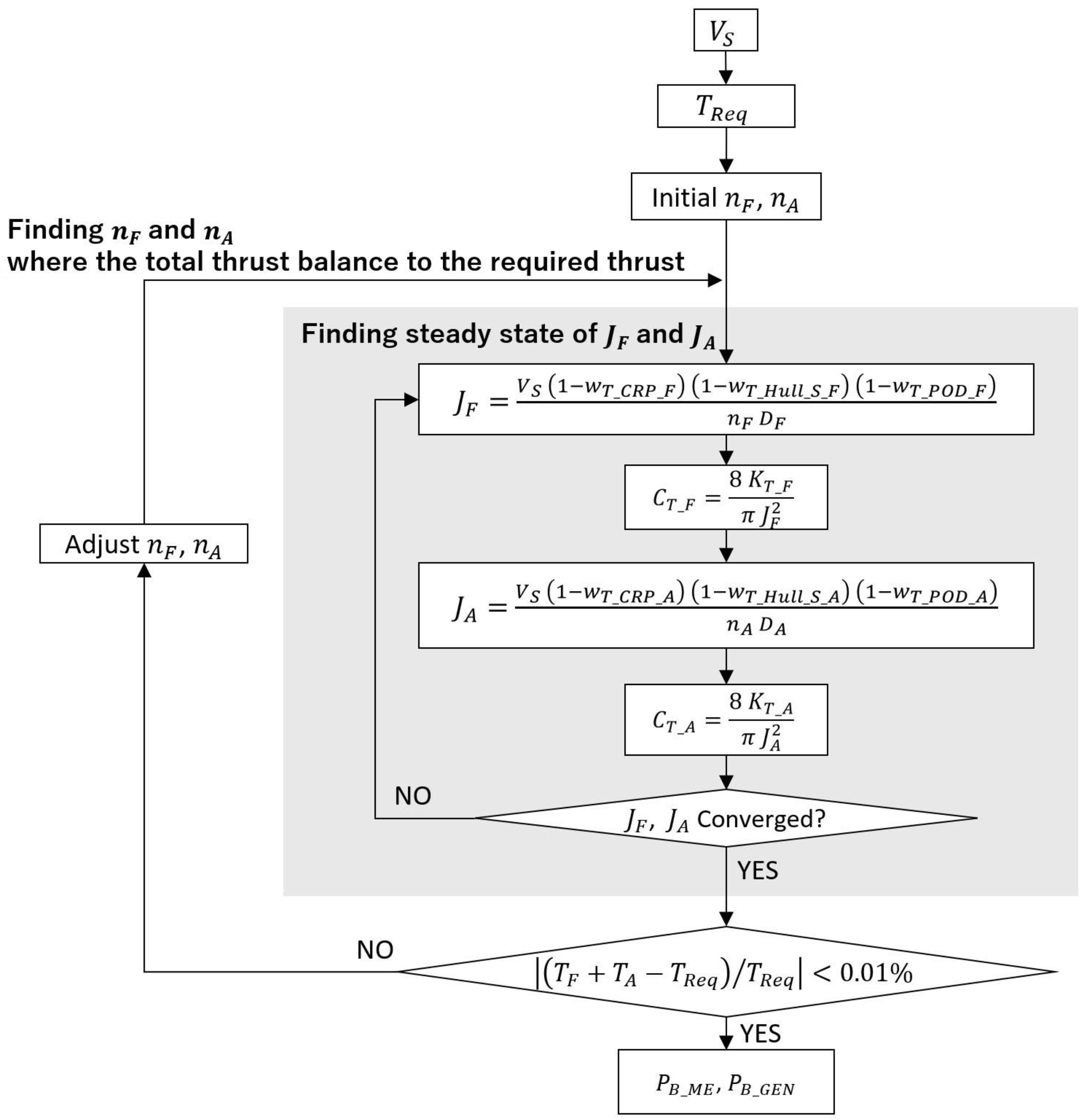
The single propeller approach, which is described in the ITTC RP, treats the total thrust of the entire propulsion system as that of a single propeller. The advantage of this approach is its simplicity of calculation. However, it is not applicable when the rotational speed ratio of two propellers C N varies, because CRP interaction at a specific C N is fixed within the total unit open water characteristics. The proposed method in this section utilizes propeller open water characteristics under isolated conditions and accounts for interactions separately, allowing this method to be applied to to arbitrary values of C N . A flowchart of the proposed powering method is shown in Figure 3. In the following subsections, each computational step is explained according to the flowchart.

2.2.1. Required Thrust

Required thrust T R e q can be determined in the same way as for a single propeller ship. This can be based on a 3D extrapolation process from model to full scale, which is described in the 1978 ITTC Performance prediction method [23].

2.2.2. Scaling for Wake Fraction of Hull

The wake fraction of the hull must be corrected to that of full scale. The scaling factors for wake fraction of each propeller can be applied to convert from model scale to full scale. In this procedure, the wake fraction can be corrected by the same manner as with a conventional single propeller ship because the wake fraction due to hull wake is accurately separated from CRP interaction and POD–Propeller interaction with the prescribed process. One example where the scaling method can be applied is the use of Yazaki’s method, giving a scaling factor ( 1 w T _ H u l l _ S ) / ( 1 w T _ H u l l _ M ) as a function of model wake fraction, ship length, beam, and draft [24].

2.2.3. Propeller Rotational Speed

In the case of a single propeller ship, the propeller rotational speed can be immediately determined once the required thrust and inflow velocity to the propeller are given. On the other hand, for ships with a HCRP system, it is necessary to find the steady operating point of each propeller through iterative calculations, since two propellers interact with each other as a CRP system. Additionally, propeller rotational speed must be adjusted so that the total thrust is balanced to the required thrust. Initial rotational speeds n F and n A must be provided. When the propeller loading factors C T _ F , C T _ A , and CRP interaction 1 w t _ C R P _ A , 1 w t _ C R P _ F are correlated using towing tank test results, the arbitrary rotational speed ratio of two propellers C N can be set. Consequently, the advance coefficient and the propeller loading factors of each propeller, which vary due to CRP interaction, are determined using Equations (25)–(28). These equations are repeated until the advance coefficients J F and J A converge.
J F = V S   1 w T _ H u l l _ S _ F   1 w T _ P O D _ F   1 w T _ C R P _ F n F   D F
C T _ F = 8   K T _ F π   J F 2
J A = V S   1 w T _ H u l l _ S _ A   1 w T _ P O D _ A   1 w T _ C R P _ A n A   D A
C T _ A = 8   K T _ A π   J A 2
After the steady operating point of CRP interaction is obtained, the propeller thrusts must be calculated using the following equations, and the rotational speeds must be adjusted by comparing the total thrust with the required thrust. A convergence threshold of 0.01% was applied to the relative difference between the total thrust and the required thrust. This value was not derived from a specific theoretical basis but was selected as a practical example. An appropriate threshold may be freely chosen depending on the required level of precision in the analysis.
T F = ρ   n F 2   D F 4   K T _ F
T A = ρ   n A 2   D A 4   K T _ A

2.2.4. Output

Once the propeller rotational speeds are determined, the brake power of each engine can be calculated by accounting for the mechanical efficiencies of transmission between the engine and the propeller, the relative rotative efficiencies due to the hull wake and POD potential wake, and the CRP interaction, as shown in the following equations.
P B _ M E = 2   π   ρ   n F 3   D F 5   K Q _ F η R _ H u l l _ F   η R _ P O D _ F   η R _ C R P _ F   η M _ M E
P B _ G E N = 2   π   ρ   n A 3   D A 5   K Q _ A η R _ H u l l _ A   η R _ P O D _ A   η R _ C R P _ A   η M _ G E N

3. Towing Tank Test Configurations, Results

3.1. Towing Tank Test Configulations

3.1.1. Test Facility

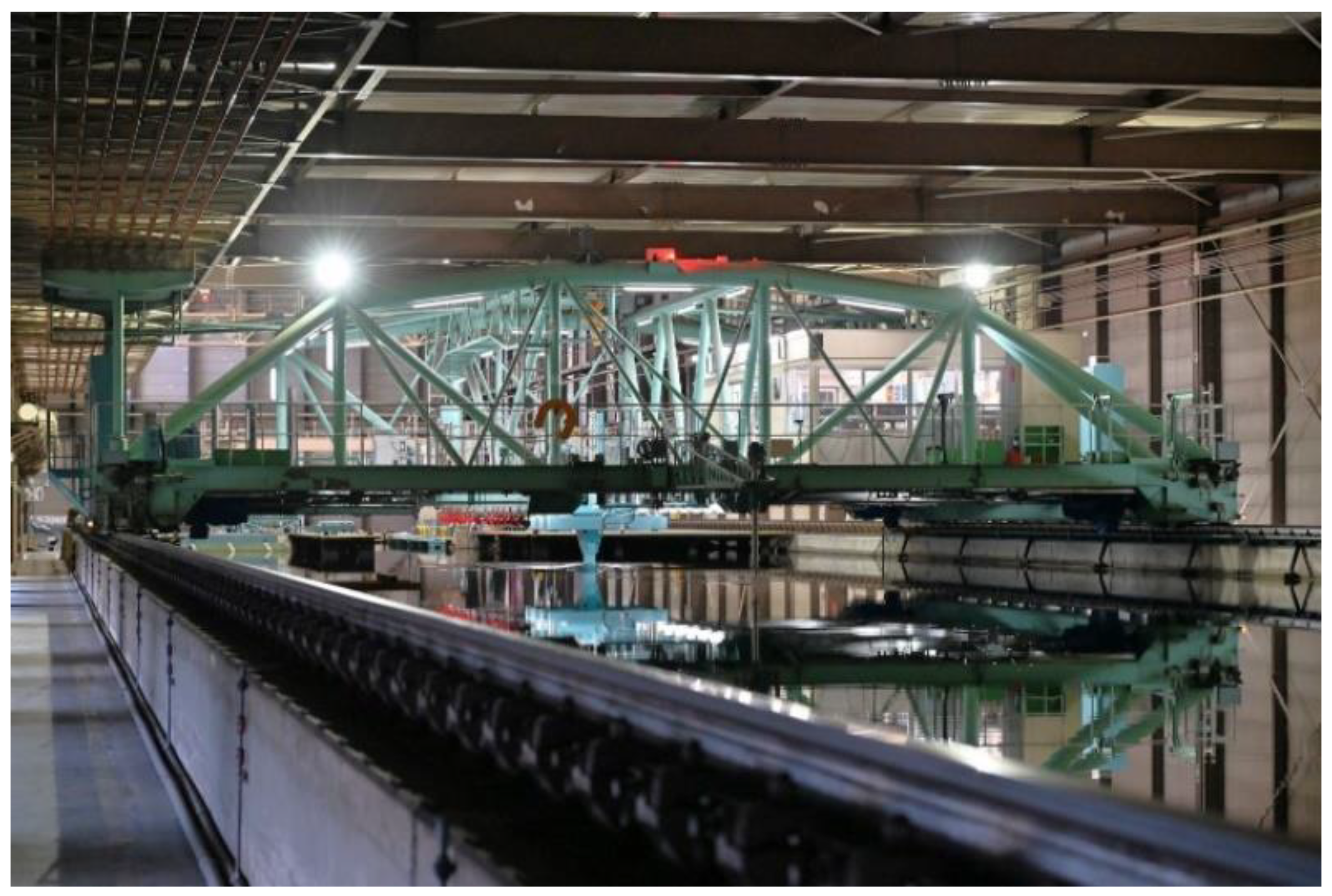
Towing tank tests were carried out at Tsu Ship Model Basin (TSMB) of Japan Marine United Corporation [25]. Dimensions of the towing tank are shown in Table 1 and a photo of the towing tank is shown in Figure 4.

3.1.2. Fluid Parameters

The measured temperature of the water in the towing tank during the tests ranged from 13.3 °C to 13.9 °C. Representative values of mass density and kinematic viscosity for fresh water at the measured temperatures were used in the analysis.

3.1.3. Model Propellers

Two model propellers that were designed as HCRP were used in the model test. Table 2 shows the principal dimensions of propellers. Figure 5 is the photographs of the model propellers used.

3.1.4. Model Ship

The hull form of the model ship was originally designed for research purposes. The dimensions of the model ship are shown in Table 3. The dimensions of the full-scale ship are defined as imaginary. The body plan is shown in Figure 6. An arrangement plan of the propulsors is shown in Figure 7. A photograph of the model ship during the self-propulsion test is shown in Figure 8.

3.2. Towing Tank Test Results

The results of the propeller open water test, resistance test, and self-propulsion test conducted on the study ship are shown in this subsection. The test results for the propeller open water characteristics, as well as the CRP interaction and POD–propeller interaction were presented by Wakabayashi et al. [19] and are reproduced here.

3.2.1. Propeller Open Water Test Result

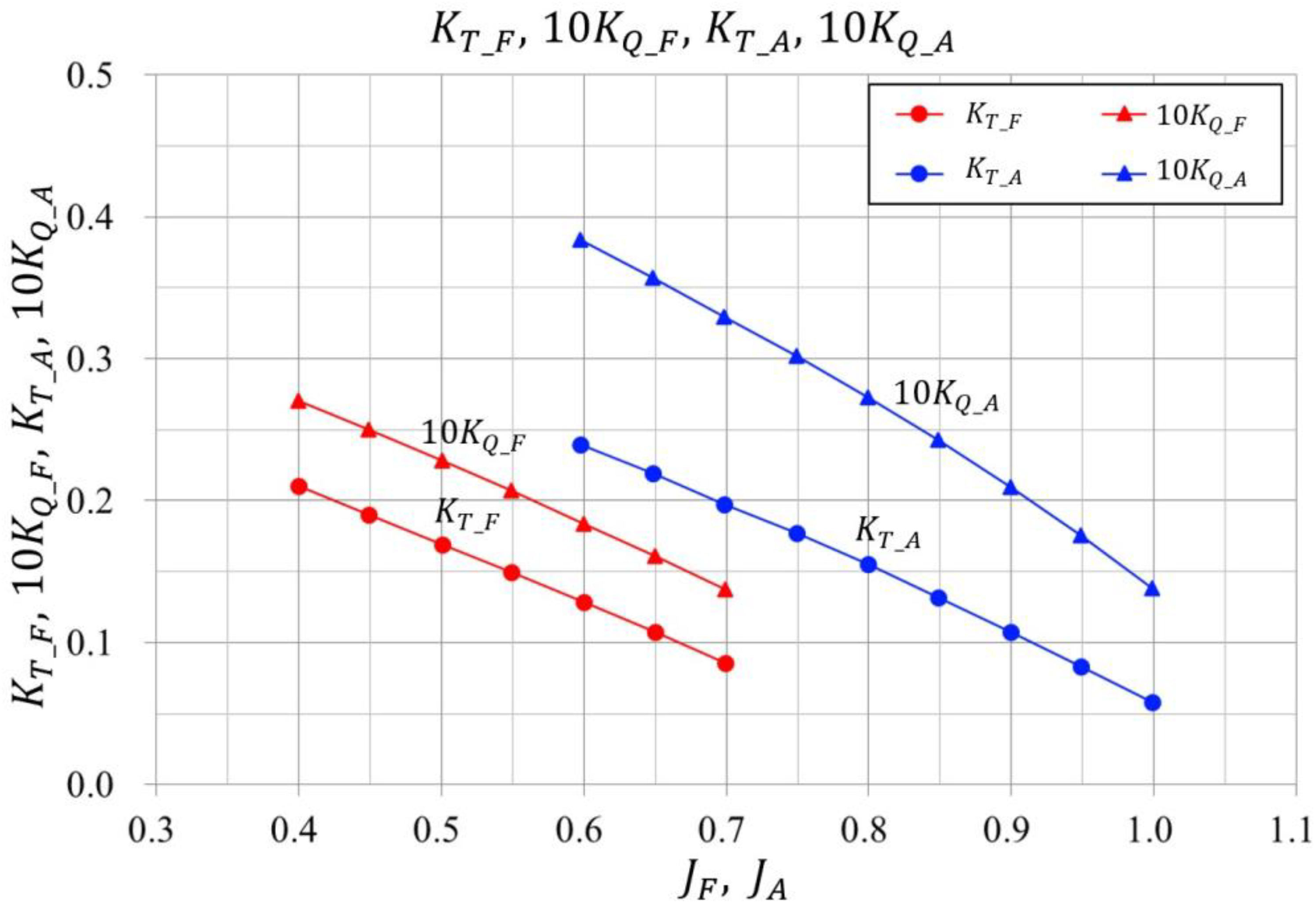
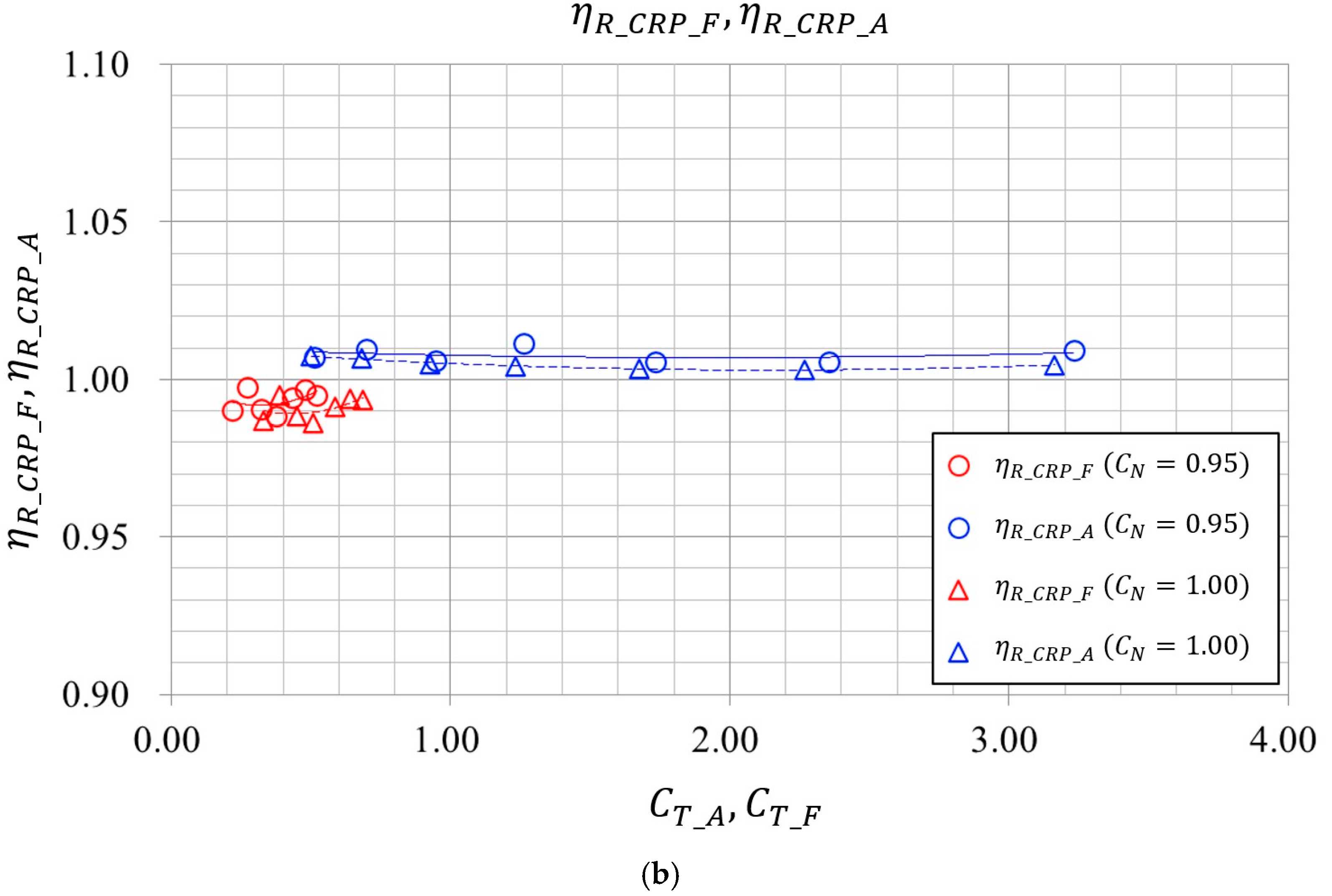
Propeller open water characteristics under isolate condition are shown in Figure 9. POD–Propeller interactions are shown in Figure 10. CRP interactions are shown in Figure 11.

3.2.2. Resistance Test Result

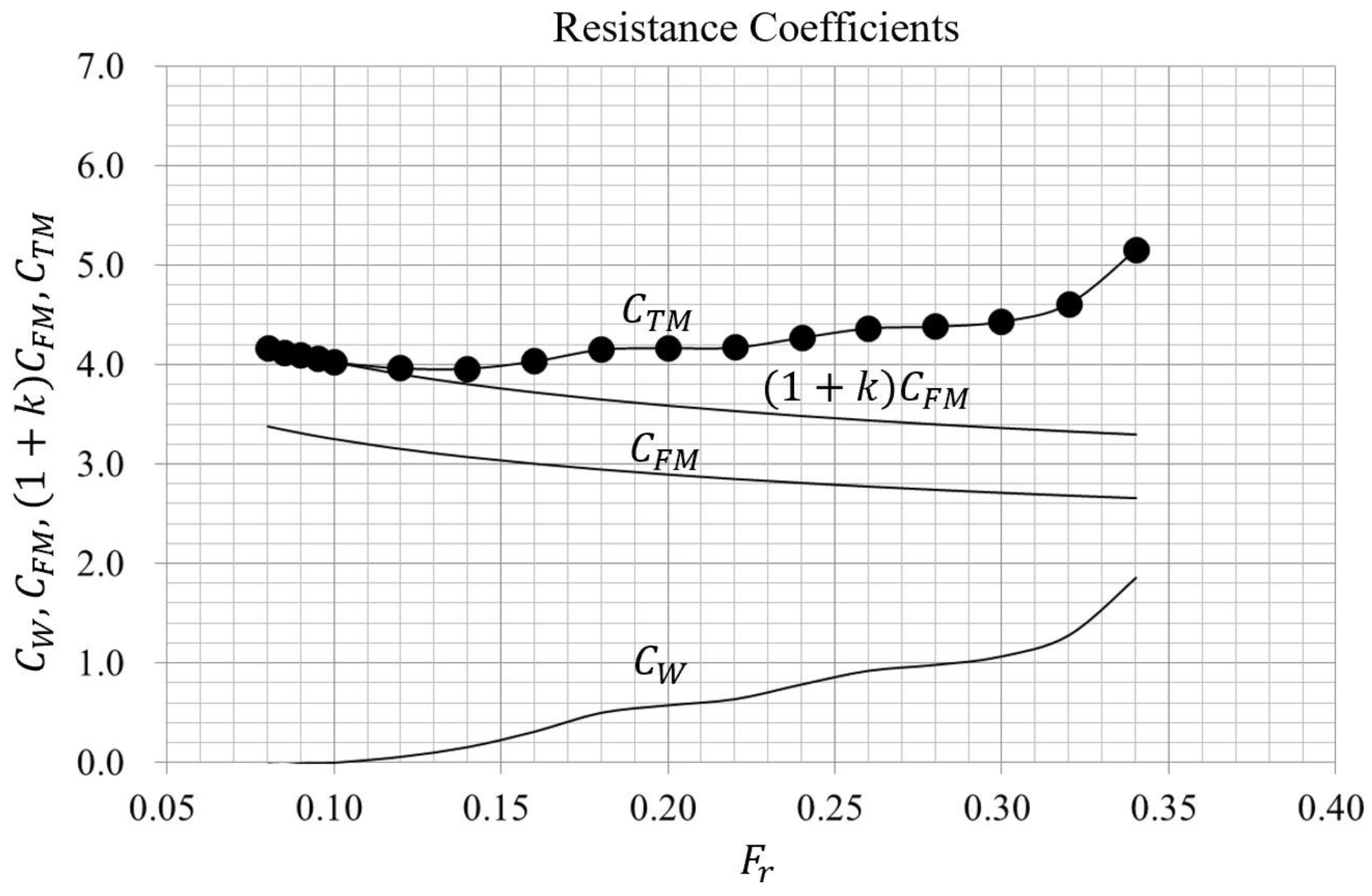
The relationship between the resistance coefficients and Froude number F r obtained via the resistance test is shown in Figure 12. Total resistance coefficient C T M is divided into frictional resistance coefficient in model scale C F M , calculated by a Schoenherr Correlation Line (ATTC line) and form factor 1 + k and wave-making resistance coefficients C W [22,23,26].

3.2.3. Self-Propulsion Test Result

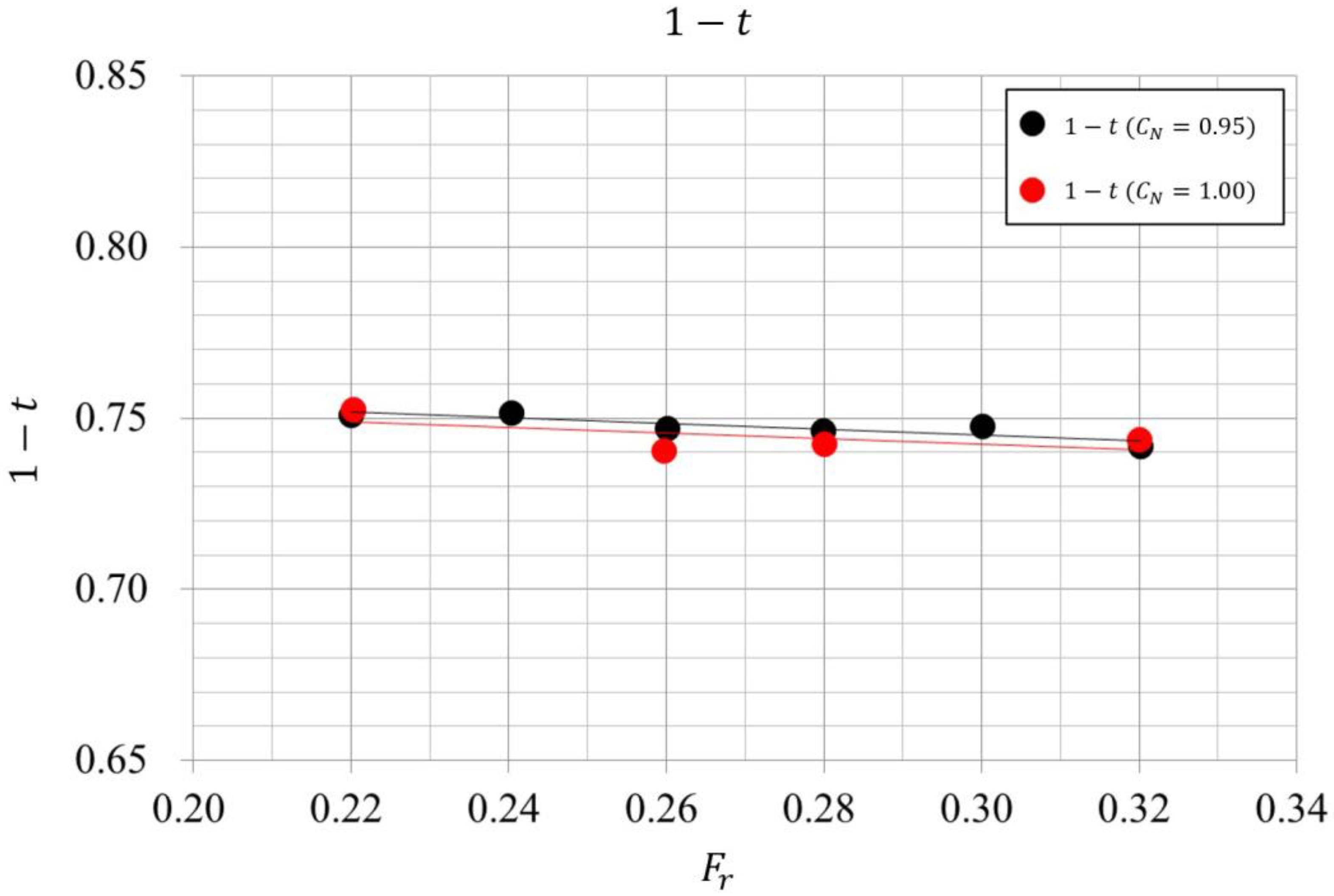
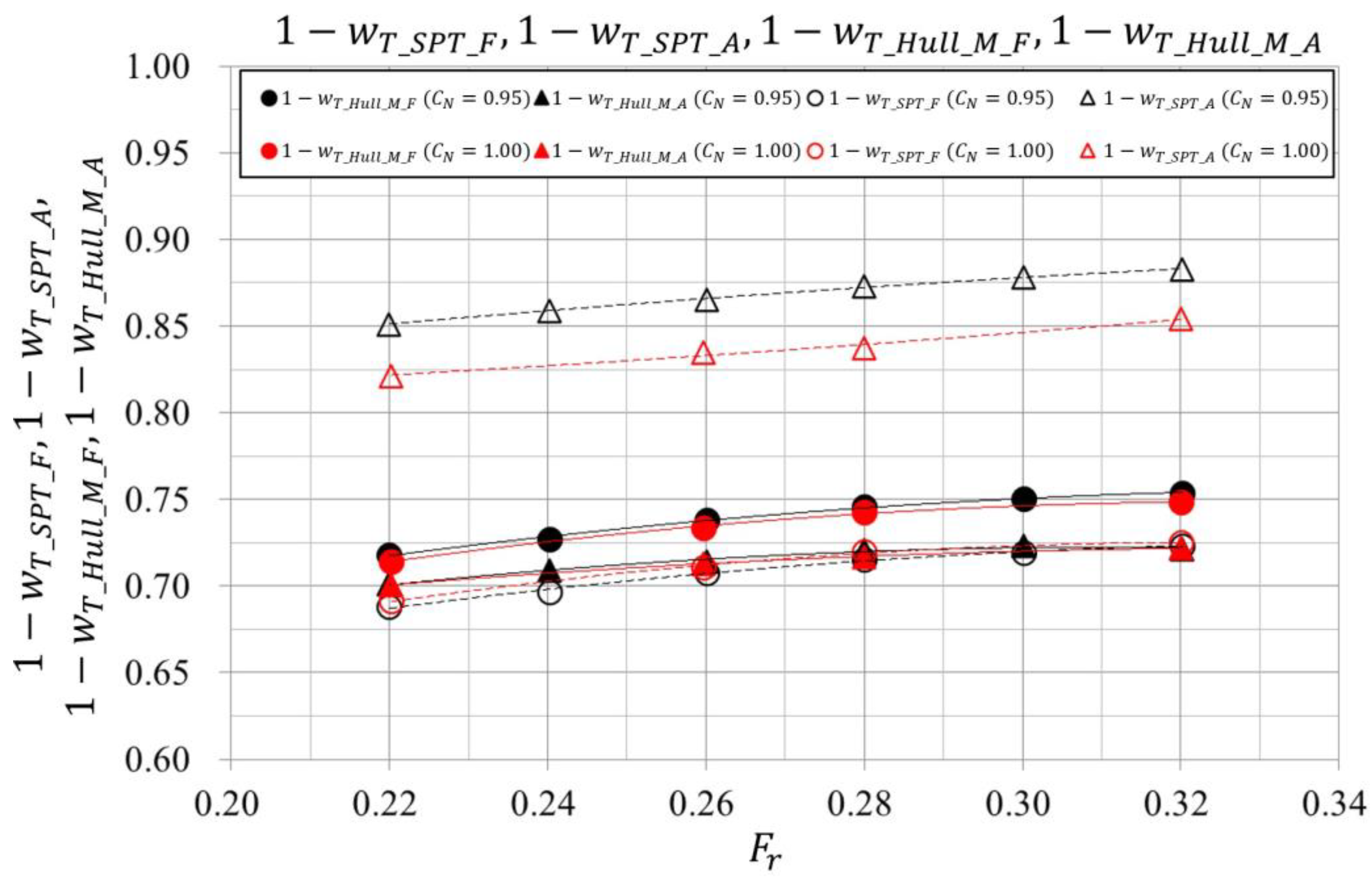
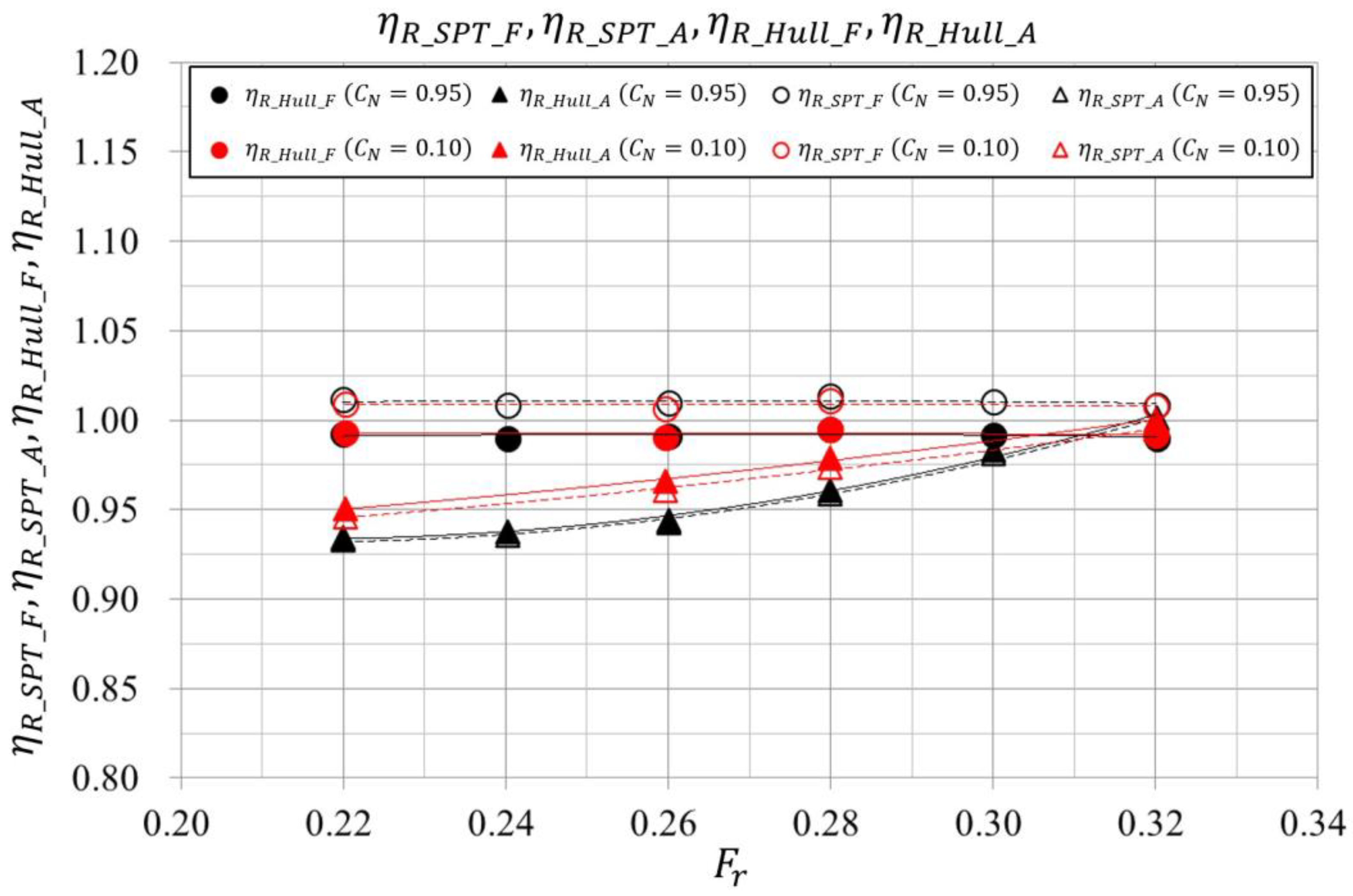
The thrust deduction factor is presented in Figure 13. 1 w T _ S P T and 1 w T _ H u l l _ M are shown in Figure 14. The proposed method is based on the assumption that interaction effects can be represented as multiplicative combinations. Non-linear interactions are reflected in the differences observed in self-propulsion test results when the rotation ratio is varied. Self-propulsion tests were conducted at the rotational speed ratio of two propellers C N = 0.95 and C N = 1.00 . Dependency on C N is not observed in 1 t . Similarly to Inukai’s report on coaxial CRP [4], 1 w T _ H u l l _ M tends to decrease as C N increases. However, this trend is not significant in the present results. η R _ S P T and η R _ H U L L are shown in Figure 15. This suggests that the assumption of multiplicative independence holds reasonably well under the tested conditions.
A slope dependent on Froud number F r is observed in the relative rotative efficiency of the aft propeller. This is considered to be caused by low Reynolds number effects due to the small diameter of the aft propeller. Although it is difficult to determine the required Reynolds number from the results of this experiment, particular attention should be paid to maintaining a sufficiently high Reynolds number for the aft propeller. In practice, using large model ships and stock propellers with large blade areas is an effective way to prevent the effect of low Reynolds number in the self-propulsion test. Additionally, applying turbulence tripping techniques such as sand roughness and turbulator for the propeller blade may be considered [27]. Theoretical corrections may be impractical under complex inflow conditions influenced by other components such as the hull, POD unit, and the other propeller. As described in Equation (32), η R _ H U L L _ A directly influences the power estimation. Therefore, any deviation caused by low Reynolds number effects during self-propulsion tests could affect the accuracy of the estimated output. Fortunately, such low Reynolds number effects were not observed in the model tests conducted with the actual hull form used for full-scale validation, which is described in the following Section 4, and thus did not impact the validation against full-scale data.

3.2.4. Estimated Speed Power Curves

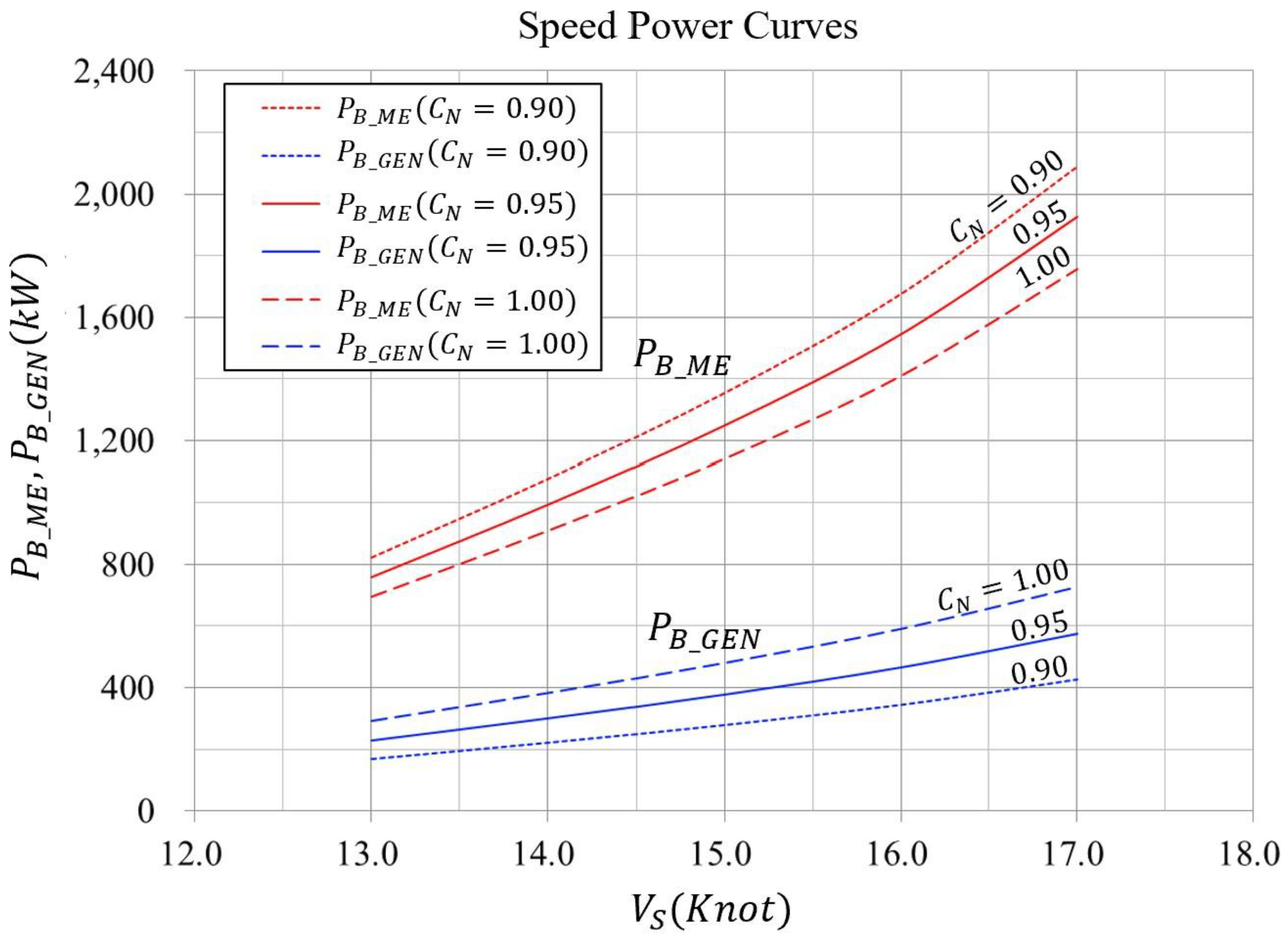
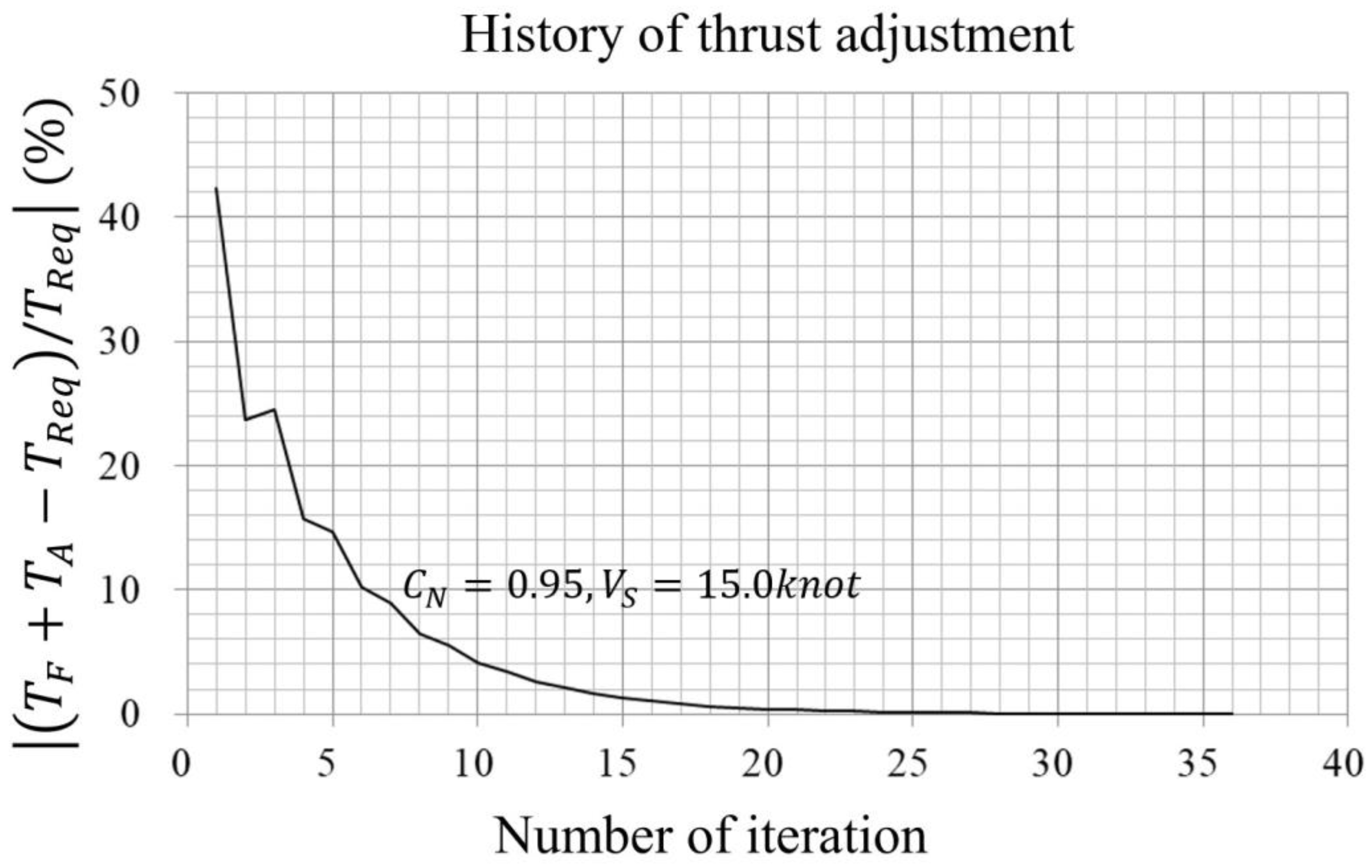
Estimated full-scale speed power curves using the present method are shown in Figure 16. These curves are derived from the towing tank test results at C N = 0.95 , and extrapolated to C N = 0.90   and C N = 1.00 . Furthermore, the present method allows estimation at arbitrary values of C N . History of thrust adjustment at C N = 0.95 and V S = 15.0   k n o t is shown in Figure 17. A total of 36 iterations were required to meet the convergence criteria. The number of required iterations depends on the initial setting of the rotational speed of propeller.

4. Validation with Speed Trial in Actual Sea

The power estimation method based on towing tank test results proposed in the previous sections utilizes the correlation coefficient between the model ship and full-scale ship. To apply this method to actual ship design, it is essential to validate its accuracy by comparing the estimated performance with the sea trial results of the actual ship. In this section, a validation study using sea trial results of a survey vessel is described. The principal particulars of the vessel are shown in Table 4. It should be noted that this vessel differs from the study ship used in the previous sections. Towing tank tests for this vessel were conducted for the power estimation. Additionally, sea trials were performed with an actual vessel, which included speed trials with a constant rotational speed ratio of two propellers C N and rotational speed ratio C N variation tests.

4.1. Speed Trial at Constant Rotational Speed Ratio of Two Propellers C N

Speed trials were conducted with a constant rotational speed ratio of two propellers denoted as C N . Pitch of the fore CPP and rotational speed ratio of two propellers C N were maintained at their designed values throughout the tests. The trial course was one mile in length and double runs were performed in the reciprocal heading at the five different engine settings. The sea conditions during the speed trials were calm, with true wind velocity below 2 m/s. The speed power curves are shown in Figure 18; note that axis ticks and values are omitted due to confidentiality. Solid lines show predicted power curves using the present method, while mean values of the double runs are plotted as circular markers. A good agreement is observed between the predicted performance and the actual speed trial results, indicating the reliability of the proposed prediction method.
Table 5 shows the deviations between estimated total power P B _ M E + P B _ G E N and measured value. M1 to M5 are arranged in order of increasing output, with M1 having the lowest output at sea trial. The maximum value of estimation error is approximately 5% for M1. At higher output levels, better agreement is observed. In both towing tank tests and sea trials, the influence of disturbances tends to be relatively large at low output levels. Therefore, it is a natural tendency that the estimation error is largest for M1, which corresponds to the lowest output.

4.2. Rotational Speed Ratio Variation Test

The rotational speed ratio variation test was conducted at actual sea. The pitch angle of CPP and the rotational speed of the fore propeller were kept constant, while the rotational speed of the aft propeller was adjusted to set C N = 0.92 ,   0.96 ,   0.99 . These tests were conducted around the design speed, and due to the output limitations of the POD system, it was not possible to increase C N beyond 0.99. Conversely, reducing C N below 0.92 causes the aft propeller to approach a nearly idling condition due to the accelerated flow by the fore propeller, which diminishes the benefit of HCRP. Therefore, the tested C N range reflects the practical operational envelope of the vessel.
A straight course was maintained throughout the test. Each measurement course was set to one mile, and measurement was started after confirming the stability of the ship’s speed at each output, as shown in Figure 19. The effects of wind and waves during the test were not corrected in the tested result and not considered in the estimation.
The changes in power distribution P B _ M E / ( P B _ M E + P B _ G E N ) resulting from C N variation are shown in Table 6, along with the estimated values based on the towing tank test results. A 11% decrease in power distribution was observed due to a 7% increase in rotational speed ratio during the sea trial, while the estimated value was a 10% decrease in power distribution. The relationship between the rotational speed ratio of the two propellers and the power distribution is well predicted by the presented method.

5. Conclusions

A new tank testing and powering method for HCRP propulsion systems has been developed. The proposed method enables accurate power estimation under an arbitrary rotational speed ratio of two propellers C N .
Towing tank tests of a study ship based on the present method were conducted. The influence of C N on the Hull–Propeller interaction was not significant in the tank test results. Full scale power estimation under various C N conditions were demonstrated for the study ship.
The proposed method was validated through sea trial of the actual ship, including speed trial under constant C N conditions and C N variation tests. The ship performance estimated with the present method showed good agreement with the actual one that was obtained from the sea trial.
The proposed method is applicable to a wide range of ships equipped with a HCRP system. The scope of the proposed method primarily covers ocean-going transport vessels, which are significant sources of global CO2 emissions. These ships generally follow standardized testing procedures, and if equipped with HCRP systems, the proposed method can be applied directly. However, further consideration may be required for the ships with unconventional propulsor arrangement or special type of ships.
From a design perspective, the performance prediction using CFD is expected to play a key role in the design of HCRP systems [28,29,30,31]. To make CFD-based design procedures practically applicable, validation using both towing tank tests and sea trial results is essential. One example of the model scale measurement data and the full-scale estimation was shown in this paper. Although the hull form used in the model tests was originally designed for research purposes, the testing methodology itself remains consistent regardless of the hull design. Therefore, the disclosed model test results can serve as useful reference data for estimating the performance of actual ships. To enhance the reliability and robustness of the proposed method for reliable and optimized ship design, further data collection from a wider variety of ship types is necessary.

Author Contributions

Methodology, T.W. and T.K.; Validation, T.W.; Formal analysis, T.W.; Investigation, T.W. and T.K.; Writing—original draft, T.W.; Writing—review & editing, T.K.; Visualization, T.W.; Supervision, T.K.; Project administration, T.W. All authors have read and agreed to the published version of the manuscript.

Funding

This research received no external funding.

Data Availability Statement

The original contributions presented in this study are included in the article. Further inquiries can be directed to the corresponding author(s).

Conflicts of Interest

Author Tomoki Wakabayashi is employed by the Technical Research Center, Japan Marine United Corporation . The remaining authors declare that the research was conducted in the absence of any commercial or financial relationships that could be construed as a potential conflict of interest.

Abbreviations

The following abbreviations are used in this manuscript:
VariableDefinition
C F M Frictional resistance coefficient of a body in model scale
C N Rotational speed ratio of two propellers
C T Propeller loading factor
C T M Total resistance coefficient in model scale
C W Wave making resistance coefficient
D Propeller diameter
F D Towing force in self-propulsion test
F r Froude Number
J Advance coefficient of propeller
k Three-dimensional form factor on flat plate friction
K Q Torque coefficient
K T Thrust coefficient
n Rate of revolution
P B Brake power
Q Propeller torque
R T Total resistance
t Thrust deduction fraction
T Propeller thrust
T R e q Required thrust accounting for thrust deduction and total resistance
V A Advance speed
w T Thrust wake fraction
η M Mechanical efficiency of transmission between engine and propeller
η O Propeller efficiency in open water
η R Relative rotative efficiency
ρ Mass density of water
SubscriptDefinition
A The association with aft propeller
C R P The effect due to CRP interaction
F The association with fore propeller
H u l l The effect due to Hull-Propeller interaction
M The association with model scale ship
P O D The effect due to POD-Propeller interaction
S The association with full scale ship
S P T The total effect due to CRP, POD and hull at self-propulsion test

References

  1. IMO. 2023 IMO STRATEGY ON REDUCTION OF GHG EMISSION FROM SHIPS. Resolut. Mepc. 2023, 377, 2023. [Google Scholar]
  2. Soltani Motlagh, H.R.; Issa Zadeh, S.B.; Garay-Rondero, C.L. Towards International Maritime Organization Carbon Targets: A Multi-Criteria Decision-Making Analysis for Sustainable Container Shipping. Sustainability 2023, 15, 16834. [Google Scholar] [CrossRef]
  3. Issa-Zadeh, S.B.; Garay-Rondero, C.L. Maritime Pilotage and Sustainable Seaport: A Systematic Review. J. Mar. Sci. Eng. 2025, 13, 945. [Google Scholar] [CrossRef]
  4. Inukai, Y. Development of Electric Propulsion Vessels with Contra-Rotating Propeller. J. JIME 2011, 46, 26–32. [Google Scholar] [CrossRef]
  5. Shimamoto, H.; Takeda, A.; Miyake, S. Tandem Hybrid CRP(Contra-Rotating-Propeller) System. J. JIME 2011, 46, 39–42. [Google Scholar] [CrossRef]
  6. Nakamura, S.; Ohta, T.; Yonekura, K.; Sasajima, T.; Sakai, K. World’s First Contra-Rotating Propeller System Successfully Fitted to a Merchant Ship. In Proceedings of the Eleventh International Marine Propulsion Conference and Exhibition, Amsterdam, The Netherlands, 27–29 November 1989. [Google Scholar]
  7. SNishiyama; Sakamoto, Y.; Ishida, S.; Fujino, R.; Oshima, M. Development of Contrarotating-Propeller System for Juno-A 37,000-DWT Class Bullk Carrier. Trans. Soc. Nav. Archit. Mar. Eng. 1990, 98, 27–52. [Google Scholar]
  8. Mewis, F. The Efficiency of Pod Propulsion. In Proceedings of the Twenty Second International Conference HADMAR 2001, Varna, Bulgaria, 1–4 October 2001. [Google Scholar]
  9. The First Hybrid CRP-POD Driven Fast ROPAX Ferry in the World. Available online: https://www.mhi.co.jp/technology/review/pdf/e416/e416338.pdf (accessed on 19 August 2025).
  10. Quereda, R.; Veikonheimo, T.; Pérez-Sobrino, M.; Ponce, J.; Sánchez-Caja, A.; Masip, J.; González-Adalid, J.; Uriarte, A.; Nijland, M.; Kokkila, K. Model testing and scaling for CRP POD. In Proceedings of the 10th International Conference on Hydrodynamics, St. Petersburg, Russia, 1–4 October 2012. [Google Scholar]
  11. Sánchez-Caja, A.; Pérez-Sobrino, M.; Quereda, R.; Nijland, M.; Veikonheimo, T.; González-Adalid, J.; Saisto, I.; Uriarte, A. Combination of Pod, CLT and CRP Propulsion for Improving Ship Efficiency: The TRIPOD project. In Proceedings of the Third International Symposium on Marine Propulsion Smp’13, Tasmania, Australia, 5–8 May 2013. [Google Scholar]
  12. Quereda, R.; Pérez-Sobrino, M.; González-Adalid, J.; Soriano, C. Conventional propeller in CRP-POD configuration. Tests an extrapolation. In Proceedings of the Fifth International Symposium on Marine Propulsors SMP’17, Espoo, Finland, 12–15 June 2017. [Google Scholar]
  13. van Manen, J.D.; Oosterveld, M.W.C. Model Tests on Contra-Rotating Propellers. In Proceedings of the Seventh ONR Symposium on Naval Hydrodynamics, Rome, Italy, 25–30 August 1968. [Google Scholar]
  14. Inukai, Y.; Ando, J. Full Scale Performance Prediction Method for a Ship with Contra Rotating Propellers. In Proceedings of the Fifth International Symposium on Marine Propulsion SMP’17, Espoo, Finland, 12–15 June 2017. [Google Scholar]
  15. Podded Propulsion Tests and Extrapolation. ITTC Recommended Procedure and Guidelines 7.5-02-03-01.3. 2021. Available online: https://www.ittc.info/media/10178/75-02-03-013-2.pdf (accessed on 19 August 2025).
  16. Sasaki, N.; Kuroda, M.; Fujisawa, J.; Imoto, T.; Sato, M. On the Model Tests and Design Method of Hybrid CRP Podded Propulsion System of a Feeder Container Ship. In Proceedings of the First International Symposium on Marine Propulsors Smp’09, Trondheim, Norway, 22–24 June 2009. [Google Scholar]
  17. Chang, B.J.; Go, S. Study on a procedure for propulsive performance prediction for CRP-POD systems. J. Mar. Sci. Technol. 2011, 16, 1–7. [Google Scholar] [CrossRef]
  18. Hybrid Contra-Rotating Shaft Pod Propulsors Model Test. ITTC Recommended Procedure and Guidelines 7.5-02-03-01.6. 2014. Available online: https://ittc.info/media/4072/75-02-03-016.pdf (accessed on 19 August 2025).
  19. Wakabayashi, T.; Katsui, T. Propeller Open-Water Test Method for Hybrid Contra Rotating Propeller. J. Mar. Sci. Eng. 2025, 13, 858. [Google Scholar] [CrossRef]
  20. Propulsion/Bollard Pull Test. ITTC Recommended Procedure and Guidelines 7.5-02-03-01.1. 2021. Available online: http://www.ittc.info/media/9607/75-02-03-011.pdf (accessed on 19 August 2025).
  21. Open Water Test. ITTC Recommended Procedure and Guidelines 7.5-02-03-02.1. 2021. Available online: https://www.ittc.info/media/9621/75-02-03-021.pdf (accessed on 19 August 2025).
  22. Resistance Test. ITTC Recommended Procedure and Guidelines 7.5-02-02-01.5. 2021. Available online: https://www.ittc.info/media/11780/75-02-02-01.pdf (accessed on 19 August 2025).
  23. 1978 ITTC Performance Prediction Method. ITTC Recommended Procedure and Guidelines 7.5-02-03-01.4. 2021. Available online: https://www.ittc.info/media/9872/75-02-03-014.pdf (accessed on 19 August 2025).
  24. Yazaki, A. A diagram to estimate the wake fraction for an actual ship from model tank test. In Proceedings of the 12th International Towing Tank Conference, Rome, Italy, 22–30 September 1969; p. 259. [Google Scholar]
  25. Tsu Ship Model Basin. Available online: https://ittc.info/media/5616/facilities-form-jmu-tsmb.pdf (accessed on 19 August 2025).
  26. Shoenherr, K.E. Resistance of flat surfaces moving through a fluid. Trans. Soc. Nav. Archit. Mar. Eng. 1932, 40, 279–313. [Google Scholar]
  27. Schuiling, B.; Kerkvliet, M.; Rijpkema, D. An Experimental Study on Visualisation and Passive Control of Model Propeller Boundary Layers. In Proceedings of the Eighth International Symposium on Marine Propulsion Smp’24, Berlin, Germany, 17–20 March 2024. [Google Scholar]
  28. Xiong, Y.; Zhang, K.; Wang, Z.-Z.; Qi, W.-J. Numerical and Experimental Studies on the Effect of Axial Spacing on Hydrodynamic Performance of the Hybrid CRP Pod Propulsion System. China Ocean. Eng. 2016, 30, 627–636. [Google Scholar] [CrossRef]
  29. Wang, Z.-Z.; Xiong, Y.; Wang, R.; Zhong, C.-H. A numerical investigation of the scale effect of hydro dynamic performance of the hybrid CRP pod propulsion system. Appl. Ocean. Res. 2016, 54, 26–38. [Google Scholar] [CrossRef]
  30. Zhang, Y.-X.; Zhou, X.-P.; Cheng, X.-K.; Li, Y.-L. A numerical study on the interaction between forward and aft propeller of hybrid CRP pod propulsion systems. Ocean. Eng. 2019, 186, 106084. [Google Scholar] [CrossRef]
  31. Zhang, Y.-X.; Cheng, X.-K.; Feng, L. Numerical investigation of the unsteady flow of a hybrid CRP pod propulsion system at behind-hull condition. Int. J. Nav. Archit. Ocean. Eng. 2020, 12, 918–927. [Google Scholar] [CrossRef]
Figure 1. Open water test configurations [19].
Jmse 13 01740 g001aJmse 13 01740 g001b
Figure 2. Dynamometer housed within a POD casing model [19].
Jmse 13 01740 g002
Figure 3. Flowchart of the powering method.
Jmse 13 01740 g003
Figure 4. Towing tank of TSMB [19].
Jmse 13 01740 g004
Figure 5. Photograph of model propeller. ((Left): Fore propeller; (Right): Aft propeller) [19].
Jmse 13 01740 g005
Figure 6. Body plan.
Jmse 13 01740 g006
Figure 7. Arrangement plan of propulsor.
Jmse 13 01740 g007
Figure 8. Photograph of model ship during the self-propulsion test.
Jmse 13 01740 g008
Figure 9. Propeller open water characteristics.
Jmse 13 01740 g009
Figure 10. POD–Propeller interaction.
Jmse 13 01740 g010
Figure 11. CRP interaction.
Jmse 13 01740 g011aJmse 13 01740 g011b
Figure 12. Resistance coefficients.
Jmse 13 01740 g012
Figure 13. Thrust deduction factor.
Jmse 13 01740 g013
Figure 14. Wake fraction factor.
Jmse 13 01740 g014
Figure 15. Relative rotative efficiency.
Jmse 13 01740 g015
Figure 16. Speed power curves of the study ship.
Jmse 13 01740 g016
Figure 17. History of thrust adjustment.
Jmse 13 01740 g017
Figure 18. Speed power curves of the survey vessel.
Jmse 13 01740 g018
Figure 19. Sea trial method for the rotational speed ratio variation.
Jmse 13 01740 g019
Table 1. Dimensions of the towing tank.
Length240 m
Width18 m
Depth8 m
Table 2. Dimensions of the model propellers.
PositionForeAft
Diameter0.2800 m0.2221 m
Pitch Ratio0.78000.9600
Expand Area Ratio0.50000.5000
Number of Blades45
Rotation directionCWCCW
Table 3. Dimensions of the model ship.
Model ScaleFull Scale
Length7.4667 m80.000 m
Breadth1.4000 m15.000 m
Depth0.7467 m8.000 m
Draft0.4667 m5.000 m
Displacement volume2.2989 m32827.49 m3
Wetted surface area10.9125 m21252.72 m2
Table 4. Principal particulars of the survey vessel.
Length77.000 m
L/B5.5000
B/d3.1111
Fore PropellerMain engine driven CPP
Aft PropellerElectric driven Podded FPP
Table 5. Estimation error of total output of main engine and generator.
OutputError
M1−5.0%
M2−2.7%
M3−2.2%
M4−0.6%
M5−0.6%
Table 6. Result of the rotational speed ratio variation test.
Revolution RatioPower Distribution
(Present Method)
Power Distribution
(Sea Trial)
0.920.810.83
0.960.750.78
0.990.710.72
Disclaimer/Publisher’s Note: The statements, opinions and data contained in all publications are solely those of the individual author(s) and contributor(s) and not of MDPI and/or the editor(s). MDPI and/or the editor(s) disclaim responsibility for any injury to people or property resulting from any ideas, methods, instructions or products referred to in the content.