Article

Influence of Varying Fractal Characteristics on the Dynamic Response of a Semi-Submersible Floating Wind Turbine Platform

1
School of Energy and Power Engineering, University of Shanghai for Science and Technology, Shanghai 200093, China
2
Department of Civil and Environmental Engineering, School of Engineering, University of Liverpool, Brownlow Hill, Liverpool L69 3BX, UK
3
Faculty of Maritime and Transportation, Ningbo University, Ningbo 315211, China
4
Shanghai Key Laboratory of Multiphase Flow and Heat Transfer in Power Engineering, Shanghai 200093, China
*
Authors to whom correspondence should be addressed.
J. Mar. Sci. Eng. 2025, 13(9), 1708; https://doi.org/10.3390/jmse13091708
Submission received: 8 August 2025 / Revised: 29 August 2025 / Accepted: 2 September 2025 / Published: 4 September 2025
(This article belongs to the Section Coastal Engineering)

Abstract

Offshore wind turbines positioned in deepwater areas are increasingly favored due to them providing superior and stable wind resources. However, the dynamic stability of floating offshore wind turbines (FOWTs) under complex environmental loading remains challenging. This study proposes a novel semi-submersible platform featuring a fractal structure inspired by the venation of Victoria Amazonica and investigates the effects of fractal branching level and biomimetic structural height on platform motions, with the aim of enhancing the overall system stability of FOWTs. Within a high-fidelity computational fluid dynamics (CFD) framework coupled with a dynamic fluid–body interaction (DFBI) model and a volume-of-fluid (VOF) wave model, the dynamic responses of the biomimetic platform are investigated under varying fractal dimensions (Df) and structural heights. The results indicate that increasing fractal complexity enhances the local wall viscosity effect, significantly improving energy dissipation capabilities within the fractal cavities. Specifically, an eight-level fractal structure shows optimal performance, achieving reductions of approximately 16.94%, 23.26%, and 35.63% in heave, pitch, and rotational energy responses, respectively. Additionally, the increasing fractal height further strengthens energy dissipation, markedly enhancing stability, particularly in pitch motion. These findings underscore the substantial potential of biomimetic fractal designs in enhancing the dynamic stability of FOWTs.

1. Introduction

Driven by escalating worldwide energy consumption and the imperative to decarbonize the power sector, wind energy has emerged as a central focus of contemporary renewable energy research and deployment [1]. Among available wind resources, offshore sites—particularly those in deep-water regions—exhibit superior wind regimes characterized by higher mean velocities, lower turbulence intensities, and elevated energy densities, thereby offering exceptional potential for large-scale development [2,3]. Furthermore, the deployment and maturation of floating platforms in deep-water regions (>60 m) have effectively resolved the economic barriers to far-offshore wind development [4]. Consequently, harnessing wind energy through FOWTs—facilitating the shift “from land to sea” and “from shallow to deep waters”—has become an inevitable trajectory for the wind power industry [5].
At present, most floating wind turbine foundations draw on design concepts originally developed for offshore drilling platforms. Among these, semi-submersible configurations—owing to their large structural span and low center of gravity—provide substantial restoring moments and thus superior resistance to combined wind and wave loads, making them the predominant choice for floating wind farms [6,7]. However, the considerable overall dimensions of semi-submersibles render them susceptible to pronounced wave-frequency oscillations and second-order slow-drift motion, which markedly amplify the platform’s global dynamic response under wave excitation [8]. To secure safe and stable operation in complex sea states, it is therefore essential to implement dedicated stabilization measures that improve the hydrodynamic performance of semi-submersible platforms.
Muliawan et al. [9] proposed the STC concept, which integrates a spar-type floating wind turbine with an axisymmetric two-body wave energy converter on a single platform, and evaluated key responses under extreme/survival conditions. The combined system reduces the standard deviation of the spar’s pitch motion and increases wind-power production at sub-rated wind speeds. Wang et al. [10] sought to mitigate the dynamic responses of FOWTs under extreme environmental conditions by proposing a fully submersible platform stiffened with carbon fiber-reinforced composite tendons. Coupled simulations conducted in AQWA and FAST show that the proposed design markedly decreases heave and surge motions relative to a tension-leg platform, while exhibiting no significant difference in pitch response. Zou et al. [11] used AQWA to evaluate the first domestically designed semi-submersible platform, the Three Gorges Lead, under combined wind, wave, and current loads. Their results indicate that the platform’s heave and pitch motions are substantially lower than those of a conventional semi-submersible and compliant with relevant design codes, although its hydrodynamic responses remain sensitive to wind speed, current velocity, and wave height. Feng et al. [12] performed high-fidelity numerical simulations of a novel 10 MW floating platform, employing overset grids coupled with a superposed-motion technique and validating the results against wave-basin experiments. The platform’s maximum static equilibrium angle is 4.9°, its peak dynamic equilibrium angle is 5.14°, and the power-oscillation factor is 6.01%, all within design-code limits. Zhang et al. [13] proposed a new fully submersible concept that lowers the center of gravity while increasing rotational inertia to enhance system stability. Numerical analyses demonstrate that the design significantly reduces surge motions and mooring-line (ML) tensions compared with a semi-submersible baseline, and its modified heave natural frequency avoids resonance with incident waves. Cutler et al. [14] proposed a catamaran–barge-type FOWT and conducted numerical simulations at a water depth of 150 m. Compared with a standard barge-type design, it achieved a 22% reduction in tower-base bending moment, a 7% reduction in rotor thrust, and a 50% reduction in the pitch response amplitude operator. To extend floating platforms’ applicability to deeper waters, Yang et al. [15] designed a multi-column, low-center-of-gravity platform supporting a 6 MW turbine. Numerical simulations that account for second-order wave loads reveal that the platform satisfies operational criteria under both rated and extreme sea states; moreover, as sea severity intensifies, its second-order responses gradually yield to wave-frequency motions.
Prior efforts to improve floating platforms have largely refined well-developed, widely used exterior geometries. The role of interior structural design has received scant attention. Its potential to enhance hydrodynamic performance remains largely unexplored. As a result, the scope for performance gains is limited, and platform configurations risk becoming homogenized, neglecting their own structural uniqueness [16].
Mandelbrot introduced the concept of fractals in 1967 [17]. Fractal architectures are known to enhance damping, accelerate energy dissipation, and mitigate fatigue loads, thereby protecting structures [18]. Using a tree-like fractal scheme, Wu et al. [19] developed a novel crashworthy energy-absorbing design and compared its crushing behavior; the third-order configuration exhibited the highest load-carrying capacity and specific energy absorption. Through combined experiments and simulations, Bogahawaththa et al. [20] investigated Menger sponge-type fractal cubes under low-velocity impact and showed that higher-order designs markedly improve dynamic energy absorption, offering guidance for honeycomb absorber design. Because of their intricate morphologies and inherent nonlinear dynamics, the mechanisms governing energy absorption and dissipation in fractal systems are nontrivial: energy is redistributed across multiple hierarchical levels, increasing entropy and, in turn, system stability. As a distinctive aquatic plant, Victoria amazonica possesses a rib-and-vein network with pronounced fractal traits on the underside of its leaves, which contributes to stability in the energetic flows of the Amazon basin. This natural prototype exemplifies a favorable balance between structural support and hydrodynamic performance.
Inspired by the Victoria Amazonica, a plant with exceptional hydrodynamic properties, this paper proposes a novel semi-submersible platform featuring an irregular leaf-vein branching fractal structure at the bottom of the pontoons, aimed at enhancing the platform’s stability and adaptability under varying sea conditions. The CFD software Star-CCM+ (V2301) is employed, utilizing the DFBI model combined with overset mesh technology, to investigate the influence of structural fractal characteristics on the dynamic response of the new biomimetic semi-submersible platform.

2. Establishment of Geometric Model

2.1. Biomimetic Fractal Platform Inspired by Victoria Amazonica

Victoria amazonica, as shown in Figure 1, characterized by its extraordinarily large leaves and unique vein architecture, demonstrates exceptional structural load-bearing capabilities [21]. Existing research has indicated that the reticulated vein arrangement of Victoria amazonica efficiently distributes applied loads, while its robust and hollow vein structures substantially reduce weight and effectively enhance buoyancy [22].
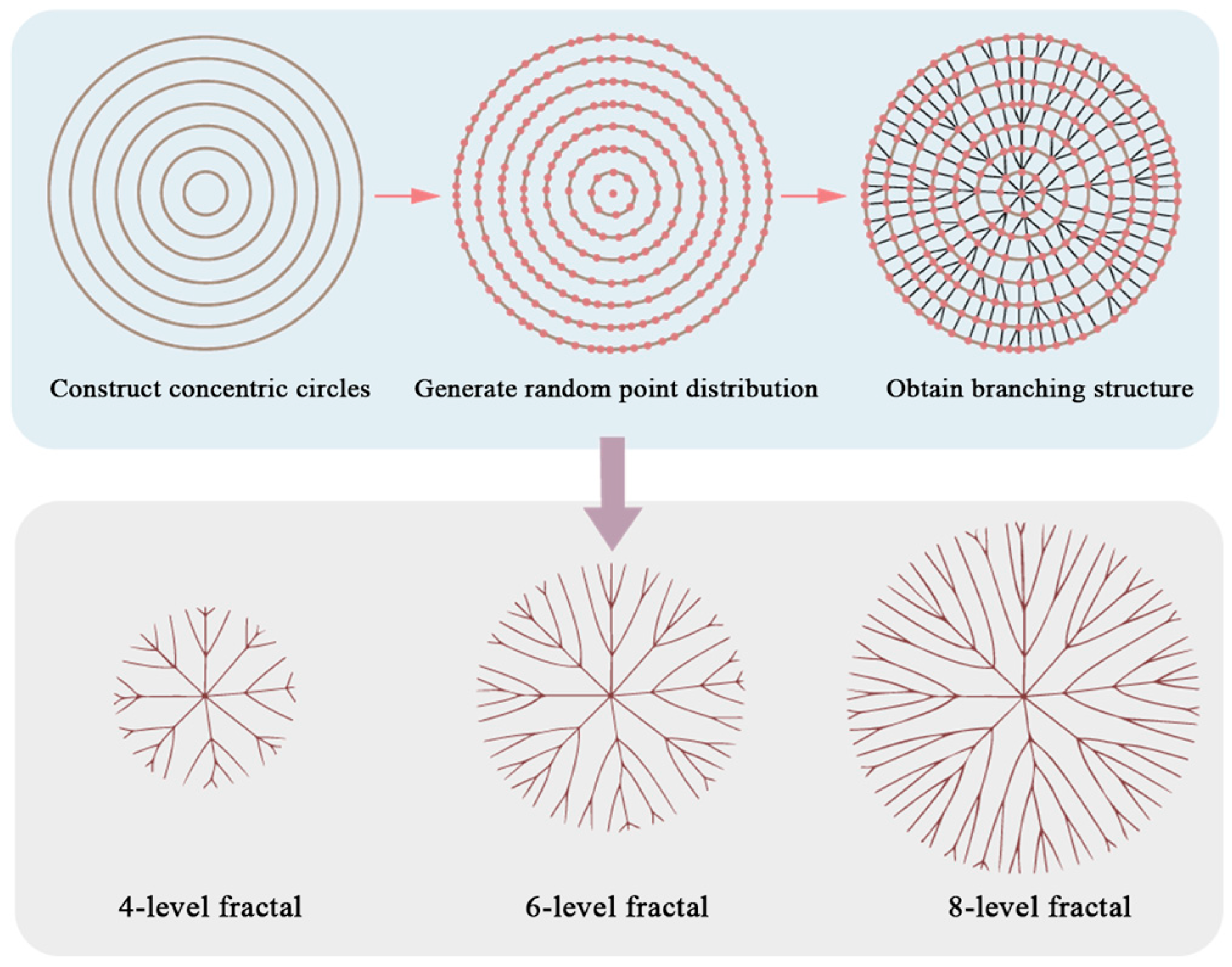
In this study, a deterministic iterative algorithm was employed for the parametric modeling of the leaf-vein branching fractal structure, with the detailed modeling procedure illustrated in Figure 2.
Here, the number of concentric circles is denoted as n (with n = 7 in the example shown in Figure 2). The iterative function used to determine the circumferential distribution number of random points on each concentric circle is given by Equation (1):
n x = y x 2 2 ,   ( x = 1 , 2 , 3 , )
where nx is the number of randomly distributed points along the circumference of the x-th concentric circle (counting outward from the center) and y is a given constant equal to 5.
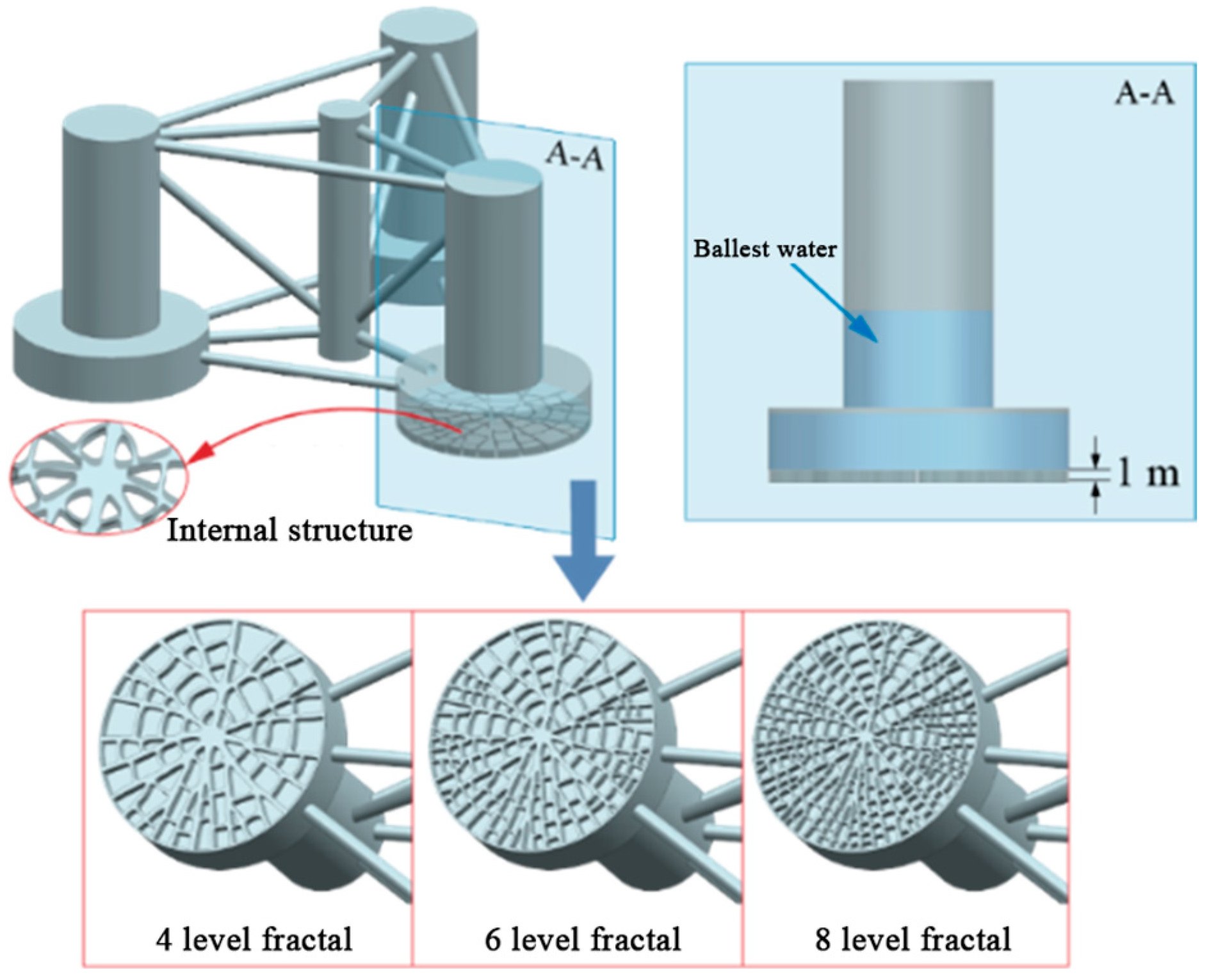
The initial fractal structure of the leaf-vein branches can be obtained by calculating the shortest paths between the mesh nodes of concentric circles. A curve-smoothing algorithm is then applied at the branching nodes to ensure structural continuity and smooth transitions. By adjusting the number of concentric circles, parametric modeling of different branching levels can be achieved. As shown in the figure, the four-level, six-level, and eight-level fractal structures correspond to four, six, and eight concentric circles, respectively. Randomly distributed rib structures are constructed between circumferential nodes on each circle, forming a complete cavity layout. These fractal branching structures are applied to the bottom of the semi-submersible platform’s pontoons, as illustrated in Figure 3. The designed fractal structures have a wall thickness of 0.06 m and heights of 1, 2, and 3 m, respectively. The internal ballast water height of the new platform is kept constant, and no ballast water is filled within the fractal cavities, allowing for an overall reduction in platform mass. This configuration facilitates a clearer assessment of the influence of lightweight bionic fractal structures on the system’s dynamic response.

2.2. Real-Scale Model of the Semi-Submersible FOWT

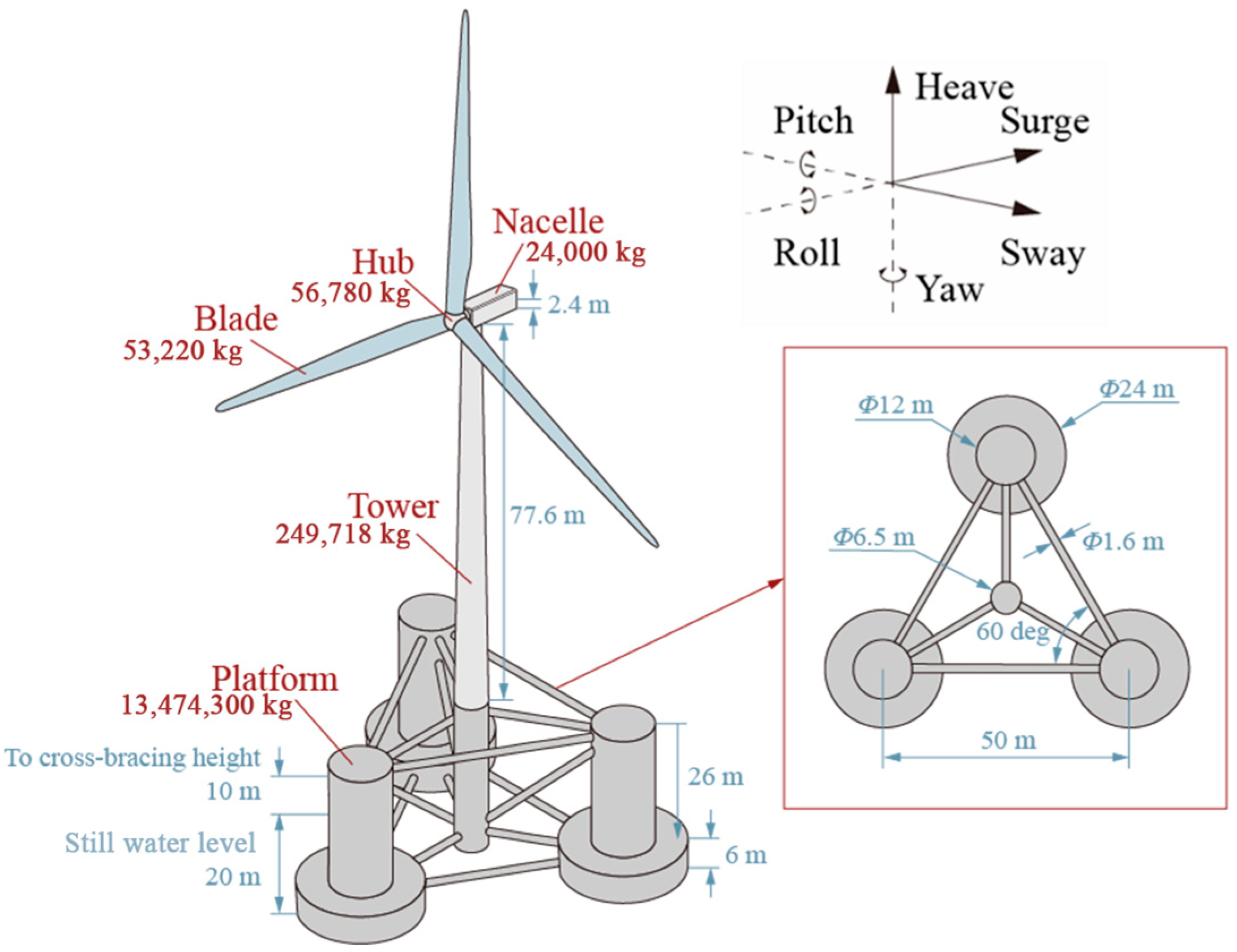
The real-scale model of the OC4 phase II semi-submersible platform supporting the NREL-5 MW wind turbine, along with the mass distribution of its components (platform, tower, nacelle, hub, and blades), is illustrated in Figure 4 [22]. The floating wind turbine exhibits motions with six degrees of freedom under wind and wave loading conditions, including heave, surge, sway, pitch, roll, and yaw. The parameters of the OC4 semi-submersible platform are presented in Table 1 [23].

2.3. Fractal Dimension, Df

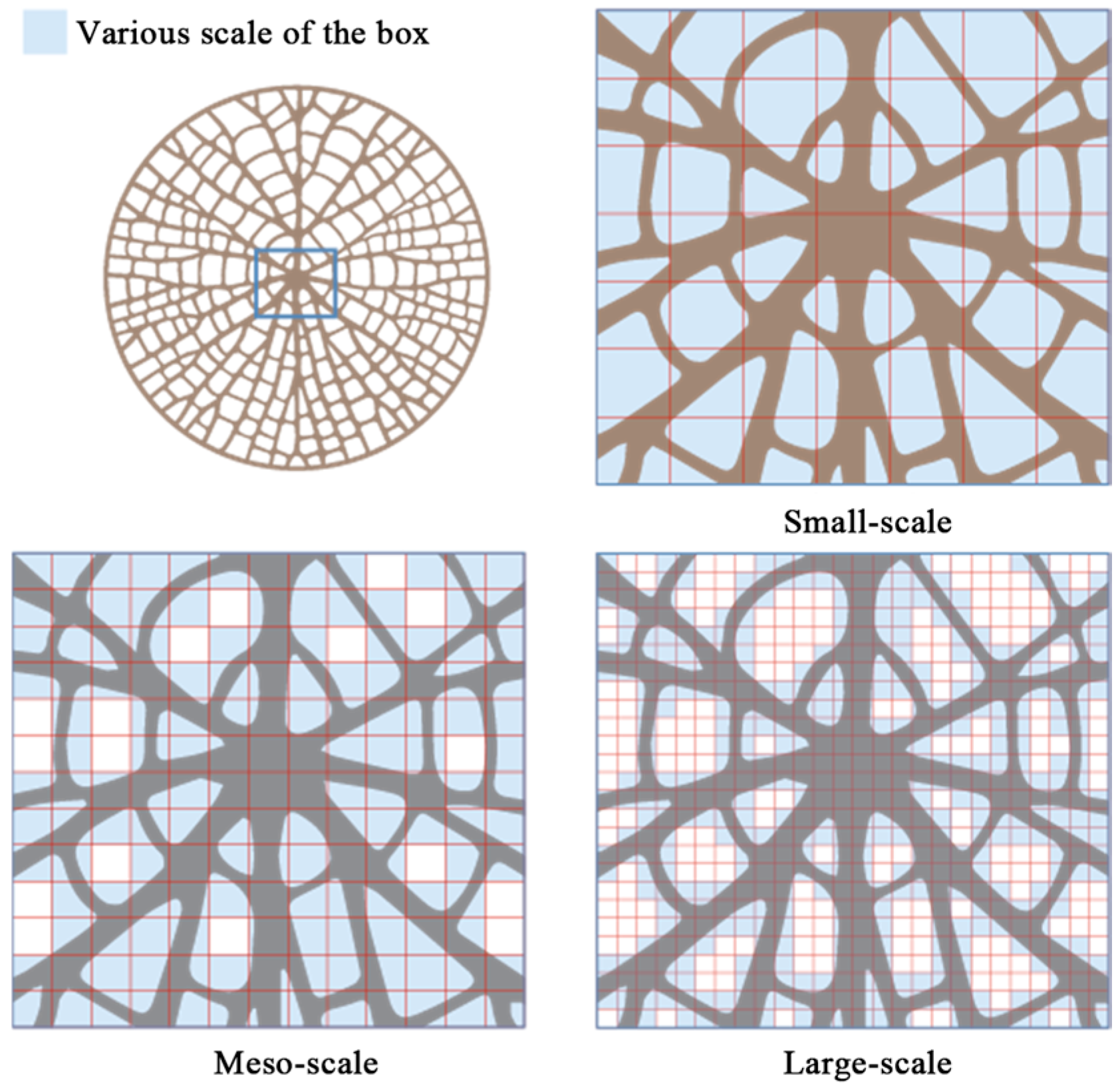
Df is employed to characterize complex geometries and quantify their self-similarity, effectively measuring the irregularity of fractal structures. A higher Df value indicates greater complexity of the geometry. Df can be determined using the box-counting dimension method, which involves covering the geometry with boxes of side length r, calculating the minimum number of boxes, N, required for complete coverage, and finally computing the logarithmic relationship, as expressed in Equation (2) [24]:
D f = lim r 0 log N ( r ) log ( r 1 ) = lim r 0 log N ( r ) log ( r )
The fundamental procedure for calculating the Df of the LVFS by employing the box-counting method is illustrated in Figure 5. Initially, the original image undergoes grayscale and binarization processing to eliminate irrelevant color information and noise interference. Subsequently, a series of square boxes of varying side lengths are selected, with the smallest box size approaching the resolution limit of the image and the largest covering the entire structure. For each box size r, the number of boxes (N) required to completely cover the targeted structure is counted. A double logarithmic plot is constructed from these data points, and linear regression analysis is performed. Df is then determined by calculating the negative value of the slope obtained from the linear fit.
The Df of the four-level, six-level, and eight-level fractal structures (denoted as 4 L, 6 L and 8 L, respectively) obtained via linear regression analysis are 1.313, 1.328, and 1.370, respectively, as depicted in Figure 6. The results indicate a positive correlation between the Df of the LVFS and the branching order. Specifically, the eight-level fractal structure (8 L, Df = 1.370) exhibits higher irregularity and more intricate details, demonstrating increased structural complexity at smaller scales.

3. Boundary Conditions and Mesh Division of the FOWT

3.1. Boundary Conditions of the FOWT

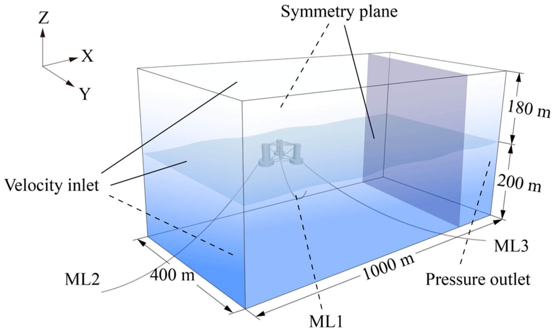
Since this study focuses on evaluating the hydrodynamic performance of the platform, only the floating platform is modeled. However, during subsequent numerical model validation, the platform mass is taken as the total system mass, accounting for the contributions of the blades, hub, tower, and nacelle. The full-scale numerical model of the semi-submersible platform and its boundary conditions are illustrated in Figure 7. The overall computational domain measures 1000 × 500 × 380 m, with a water depth of 200 m. A VOF model is employed to generate air–water two-phase flow at the velocity inlet. A fifth-order Stokes wave (wave height: 7.58 m; period: 12.1 s) propagates along the positive X-direction from the air–water interface toward the pressure outlet. To minimize the influence of wave reflections from the far-field boundary on the hydrodynamic behavior of the platform, a damping wave absorption model is applied near the pressure outlet to suppress vertical wave oscillations [25], with a damping zone length approximately equal to one wavelength (250 m).
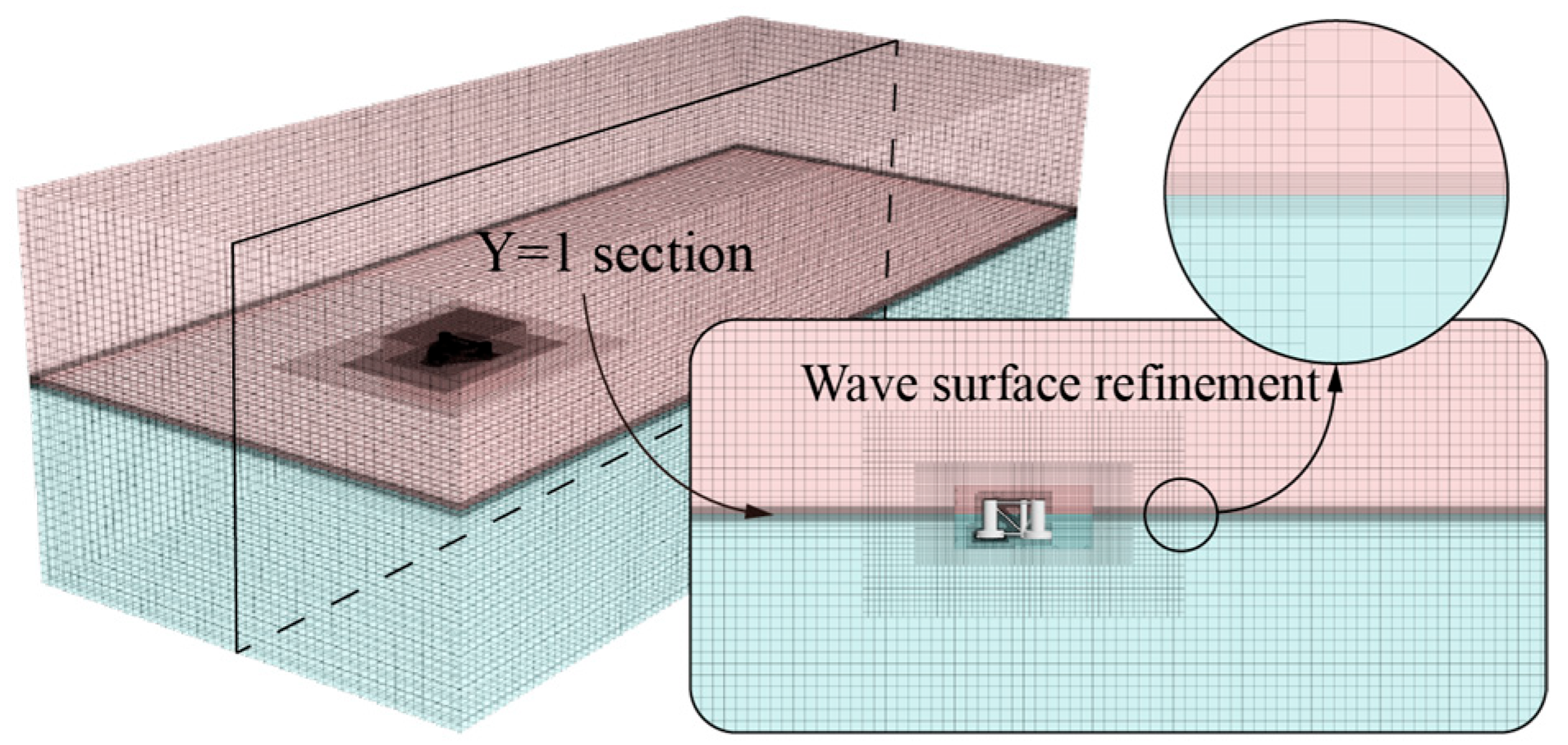
The cut-cell mesh, generated through cutting algorithms and mesh optimization techniques, enhances mesh orthogonality near boundaries and is effective in capturing variations in free-surface shape and position [26]. Therefore, a cut-cell mesh generator is employed in this study to discretize the entire computational domain, as illustrated in Figure 8. To accurately resolve wave characteristics, the mesh should contain no fewer than 20 layers in the wave height direction and at least 80 cells within one wavelength [27].

3.2. Reliability Verification

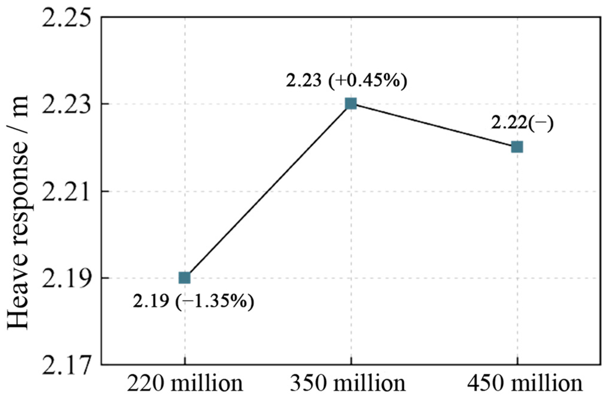
Under regular wave conditions, a mesh independence study is conducted based on the heave response amplitude to evaluate the hydrodynamic performance of the original platform (OP). By uniformly adjusting the overall mesh resolution through relative scaling, simulations are performed using meshes containing 2.2 million, 3.5 million, and 4.5 million cells, as shown in Figure 9. The results indicate that, compared to the 4.5 million-cell mesh, the heave response amplitude decreases by 1.35% with the 2.2 million-cell mesh and increases by 0.45% with the 3.5 million-cell mesh. The maximum deviation of 1.35% suggests that the heave response has achieved mesh independence. Therefore, the 3.5 million-cell mesh is deemed sufficient for the required computational accuracy, and all subsequent simulations are carried out using this mesh resolution.
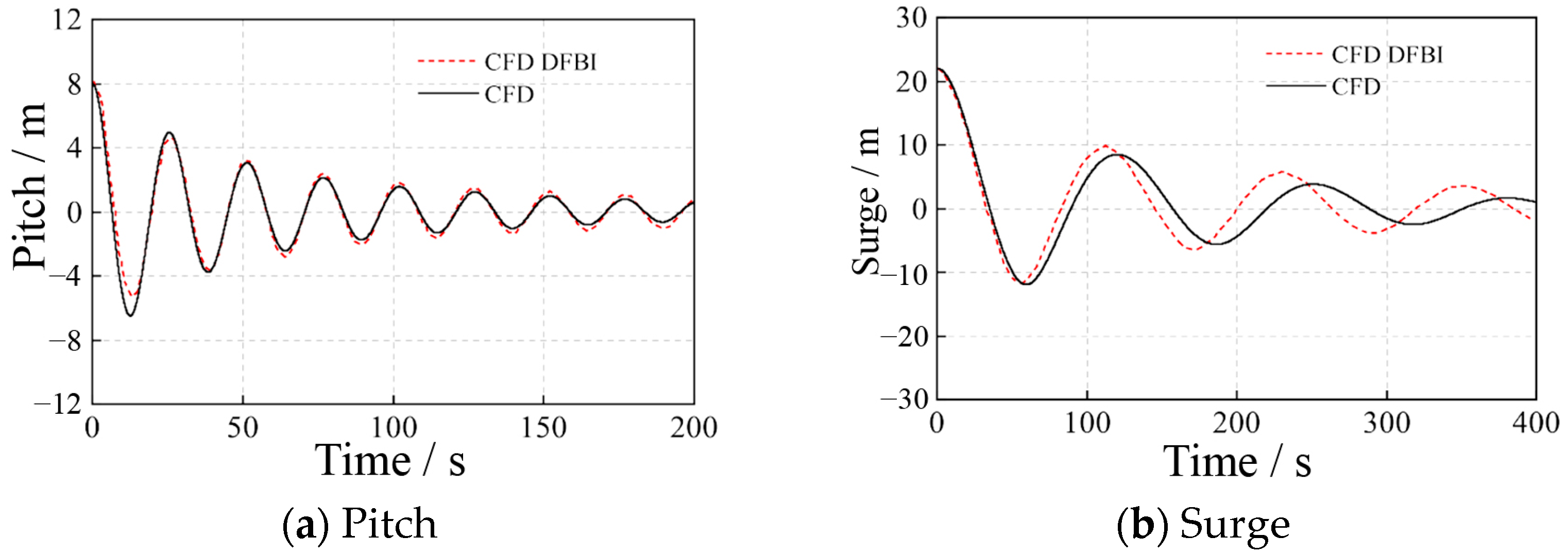
Free decay simulations are conducted for the OP, with the initial pitch angle and surge displacement set to 8° and 22 m, respectively. The results are presented in Figure 10. The pitch decay curve of the OP shows excellent agreement with the results reported in the literature [28]. For the surge decay response, the oscillation amplitude during the initial decay phase closely matches the reference values; however, as the amplitude decreases, a noticeable change in the decay period is observed. Overall, the free decay results of the OP fall within a reasonable and acceptable range.
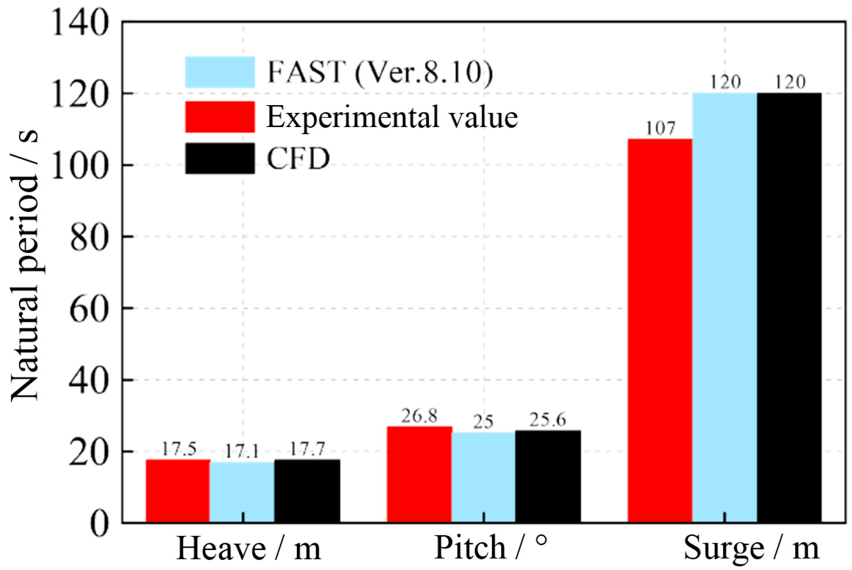
The natural periods of heave, pitch, and surge decay for the OP are shown in Figure 11. As observed, the CFD-derived natural periods for heave, pitch, and surge exhibit good agreement with the results reported in the literature [28]. The mooring used in this study is a quasi-static catenary model with nonlinear stiffness. However, due to the exclusion of the seabed contact and buoyancy effects of the actual mooring system, the surge natural period obtained in this study shows some deviation from the experimental values reported in [29], while the heave and pitch natural periods remain highly consistent. These findings indicate that the numerical model of the semi-submersible floating platform developed in this study demonstrates high reliability and can be confidently used for subsequent hydrodynamic analyses of the proposed novel platform.

4. Effect of Df on Stability of Platform

4.1. Analysis of Hydrodynamic Performance

By modeling the full-scale platform and its ballast water, the masses of the OP and the four-level, six-level, and eight-level fractal bionic platforms are determined to be 13,473,421 kg, 12,642,797 kg, 12,803,742 kg, and 12,982,368 kg, respectively. The corresponding centers of gravity (measured below the waterline) are 13.460 m, 13.016 m, 13.098 m, and 13.186 m, as summarized in Table 2.
Hydrodynamic performance simulations are conducted for the original and biomimetic platforms with different values of Df under regular wave excitation, and the results are presented in Figure 12.
As shown in Figure 12a, the incorporation of fractal structures increases the draft of the semi-submersible platform while reducing its overall mass, resulting in a downward shift in the initial heave response curves of the bionic platforms. When the fractal branching level reaches eight, the average heave displacement offset is the largest. During the initial 100 s of the response, the standard deviations of heave for the 4 L, 6 L and 8 L fractal platforms are 1.033, 0.958, and 0.878, respectively—representing reductions of 2.27%, 9.37%, and 16.94% compared to the OP (1.057). This indicates that the bionic platforms exhibit improved stability during the early response stage, and the effectiveness of stabilization increases with higher fractal branching levels.
Figure 12b shows that the pitch response amplitude of the bionic platforms is also reduced compared to the OP. Over the entire response duration, the maximum pitch angles for the 4 L, 6 L, and 8 L platforms are 2.32°, 2.15°, and 1.98°, respectively. Specifically, the 8 L platform shows a 23.26% reduction in maximum pitch angle compared to the OP (2.58°). In contrast to heave and pitch, the surge response curves of the bionic platforms (Figure 12c) take longer to reach a stable oscillatory state (approximately 300 s), but the overall behavior closely matches that of the OP, with only minor differences in response amplitude.
Figure 13 illustrates the velocity responses in the heave, pitch, and surge directions. It can be observed that the reduction in pitch velocity amplitude is the most significant among all three directions, followed by heave, while surge velocity shows no notable change. Specifically, the maximum heave velocities for the 4 L, 6 L, and 8 L platforms are 0.583 m/s, 0.578 m/s, and 0.575 m/s, respectively, and the corresponding maximum pitch angular velocities are 0.0133 rad/s, 0.0131 rad/s, and 0.0131 rad/s. Although the differences among the three bionic configurations are minor, all values are substantially lower than those of the OP (1.105 m/s and 0.0194 rad/s). As for the surge velocity, the bionic platforms exhibit a similar trend to the OP, with no significant variation.
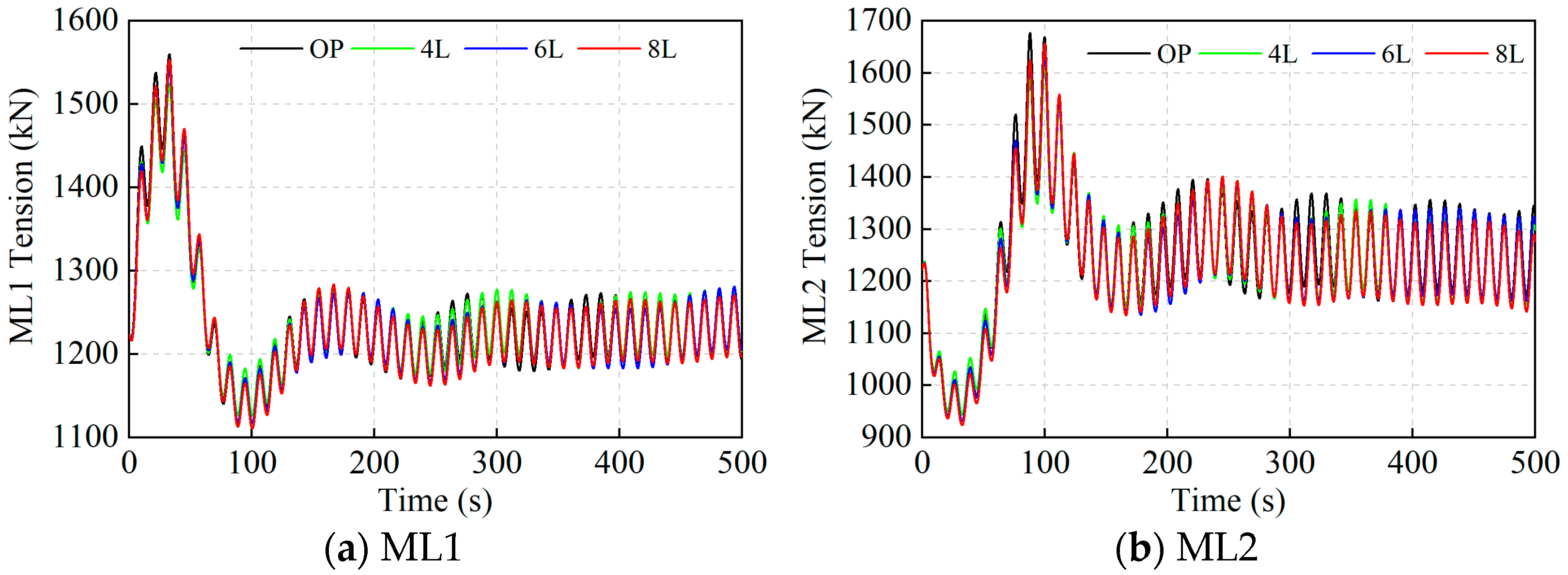
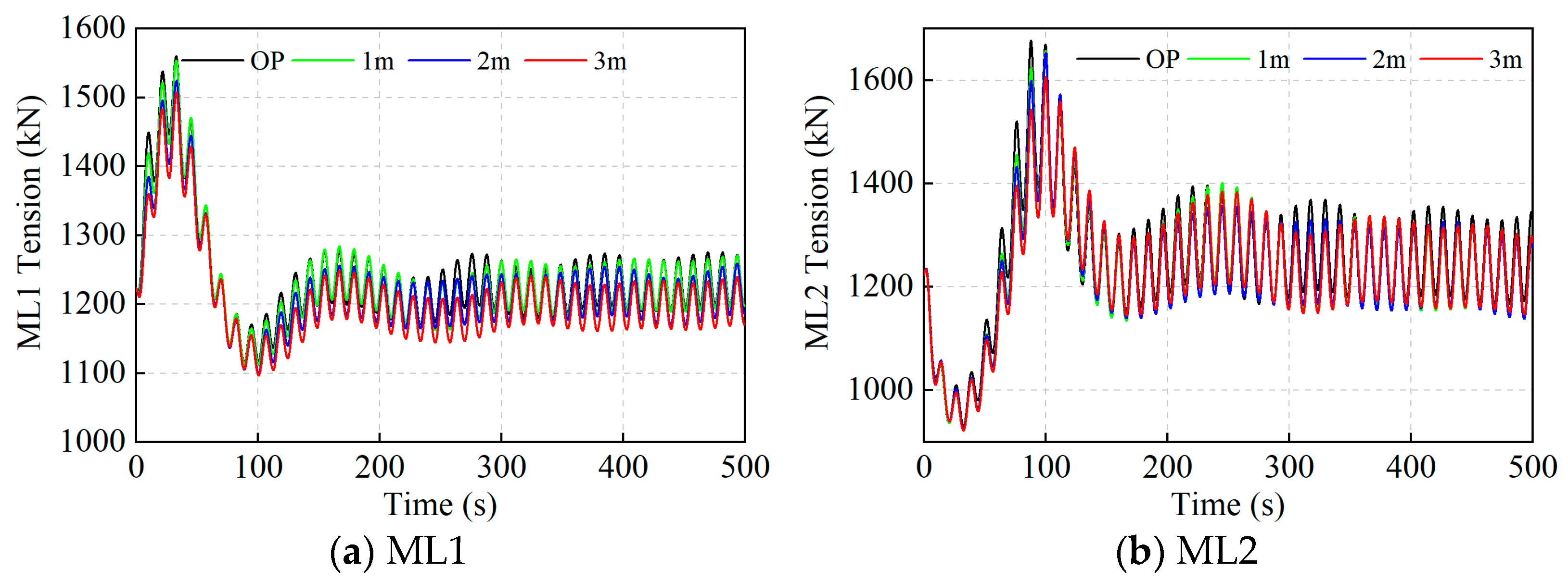
Figure 14 presents the mooring tension response results for the biomimetic and OPs. Since ML1 and ML3 are symmetrically arranged along the X-axis (the direction of wave propagation) and the platform exhibits relatively small sway (Y-axis) motion, their tension response curves show minimal differences. Therefore, only the tension responses of ML1 and ML2 are provided in this study.
As shown in Figure 14, the overall variation trends of mooring tension responses for the biomimetic and OPs are largely consistent. However, during the steady-state phase, the biomimetic platform exhibits slightly lower tension amplitudes compared to the OP. By comparing Figure 12c with Figure 14, it is evident that the mooring tension response is primarily governed by the platform’s surge motion. When the platform moves in the negative X-direction (i.e., a decrease in surge response), ML1, which is anchored in the positive X-direction, undergoes tension due to stretching, resulting in a gradual increase in tension response. In contrast, ML2, anchored in the negative X-direction, exhibits an opposite response trend.
The tension histories of ML1 and ML2 exhibit a common pattern: a transient build-up followed by a quasi-steady oscillation band. The tension can be interpreted as the sum of the mean pretension plus a low-frequency component correlated with surge and a wave-frequency component corresponding to heave/pitch. When the platform moves in the negative X-direction, ML1 is stretched and its tension gradually increases; ML2 shows the opposite trend because its fairlead is located in the negative X-direction, consistent with Figure 12c. The wave-frequency oscillations are governed by vertical/rotational motions and fairlead elevation, whereas the low-frequency envelope is set by the global radiation–diffraction field and mooring restoring/damping. Since the interior fractal cavities mainly increase wave-band hydrodynamic damping via wall-bounded viscous dissipation around the pontoons, they primarily attenuate the wave-frequency component, leading to slightly smaller steady-state amplitudes than the original platform, while the low-frequency behavior remains nearly unchanged.
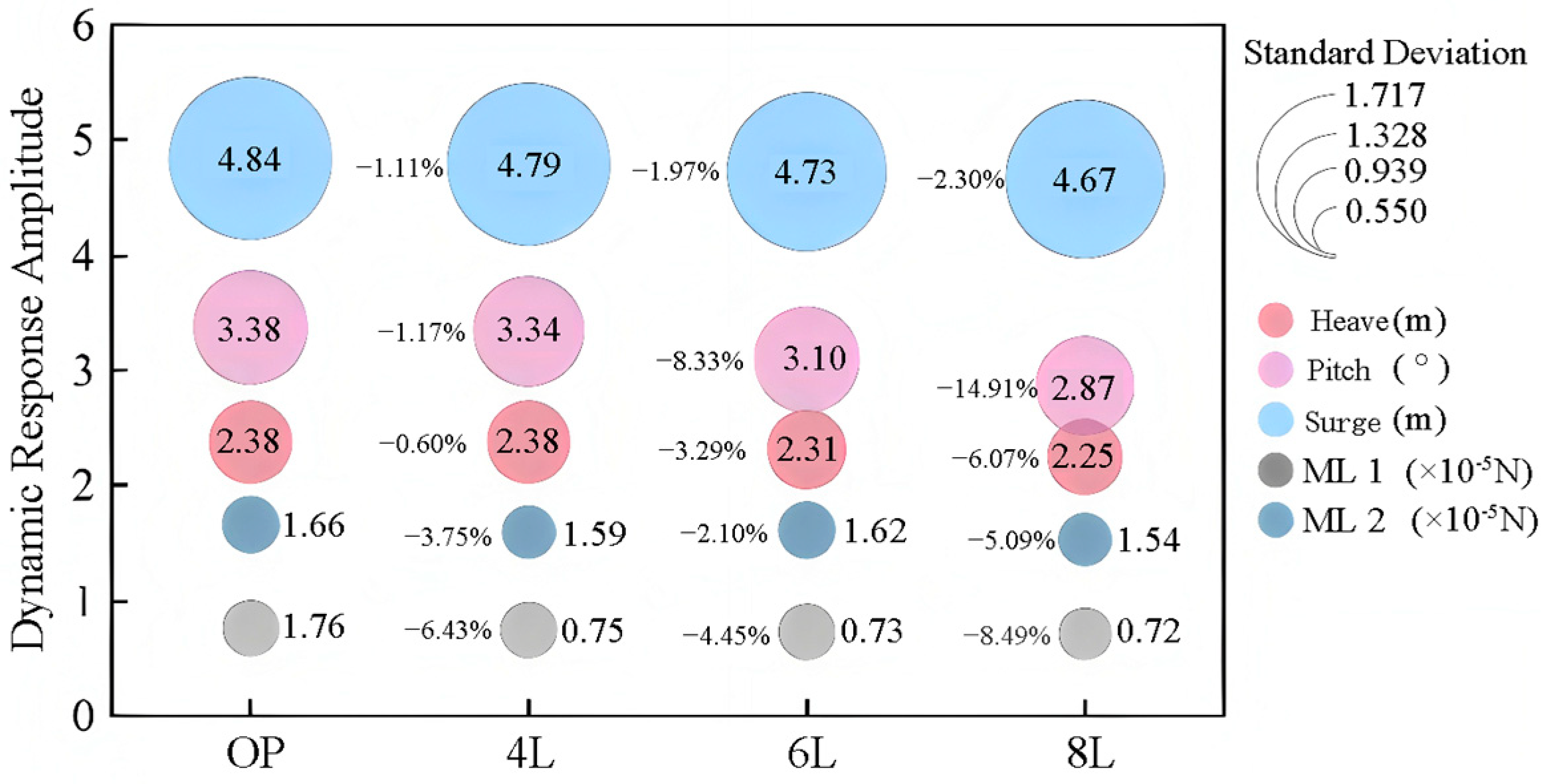
Further evaluation of the stability improvement of the bionic platforms was conducted by analyzing the average response amplitudes and standard deviations over five wave periods during the steady-state oscillation phase, as shown in Figure 15. When Df corresponds to the 4 L configuration, the average response amplitudes and standard deviations in the three principal degrees of freedom (heave, pitch, and surge) show no significant improvement compared to the OP. As Df increases, the overall stability of the bionic platforms gradually improves. Among the three motion components, the pitch response shows the largest reduction in average amplitude, followed by heave and then surge. When Df reaches the eight-level configuration, the standard deviations of the heave, pitch, and surge responses are reduced by 6.07%, 14.91%, and 2.30%, respectively, compared to the OP, indicating optimal dynamic performance.
Comparison with mooring tension responses reveals that bionic structures with different Dfs can effectively reduce both the average values and standard deviations of ML1 and ML2. When the Df is at the 8 L configuration, the improvement is most pronounced, with the standard deviations of ML1 and ML2 are reduced by 8.59% and 5.90%, respectively, compared to the OP. These results indicate that the incorporation of bionic fractal structures can effectively mitigate dynamic responses and enhance platform stability. Df plays a critical role in this improvement, with the platform achieving optimal hydrodynamic performance when Df reaches 8.
Df has little effect on surge because the inline wave-frequency excitation—set by the platform’s outer projected area and far-field diffraction/radiation—is essentially unchanged by the sheltered interior cavities. The long-period surge component is governed by second-order drift forces determined by the global potential field, to which near-wall cavity flows contribute only marginally. In addition, for semi-submersibles the surge natural period and amplitude are controlled primarily by mooring stiffness and damping; the fractal geometry does not alter mooring layout, pretension, or other equivalent properties, and any small mass change is secondary. In contrast, the interior fractal network chiefly increases wave-band hydrodynamic damping via wall-bounded viscous dissipation around the pontoons, which couples strongly to ↳heave and pitch. This frequency separation explains the observed pattern: substantial reductions in heave/pitch, with negligible change in surge.

4.2. Energy Dissipation Effects of Fractal Structures with Different Levels of Branching

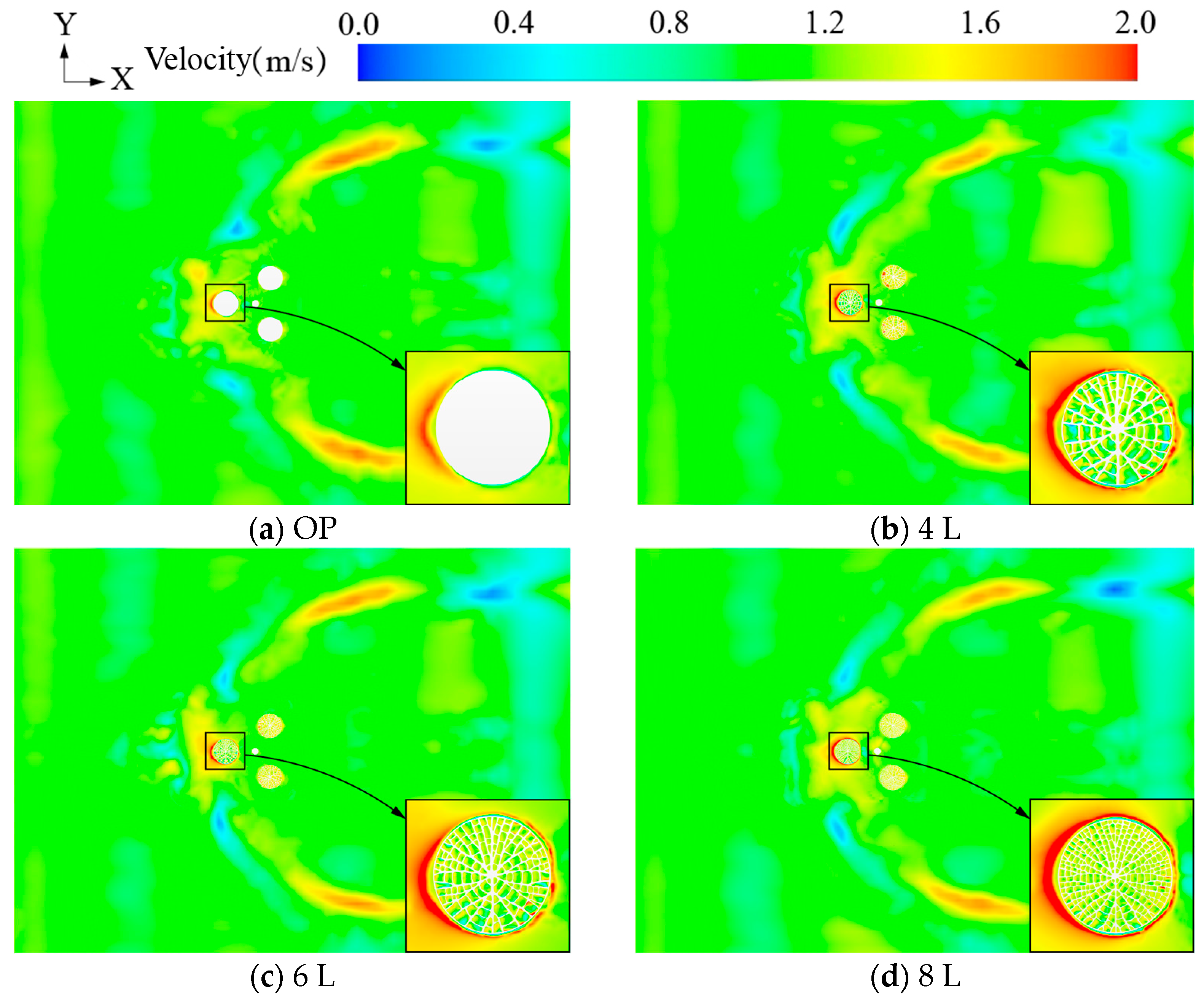
Figure 16 presents the velocity field distribution at the Z = 0.5 m cross-section, along with a localized view of the internal flow field within the fractal structure. As shown in the figure, wave propagation in the positive X-direction is obstructed by the semi-submersible platform, causing the incoming fluid to flow around the front edge of the structure. This results in an increase in local pressure, which then gradually redistributes toward the low-pressure regions on both sides. The enlarged view of the local flow field reveals that the high-velocity flow region surrounding the pontoons of the bionic platform is significantly larger than that of the OP. In addition, the acceleration of fluid within the cavities of the bionic fractal structure is notably enhanced. As Df increases, the cavity size gradually decreases, leading to an increase in internal vortex velocity. When Df reaches the 8 L configuration, the internal cavities of the fractal structure are dominated by high-velocity vortex regions.
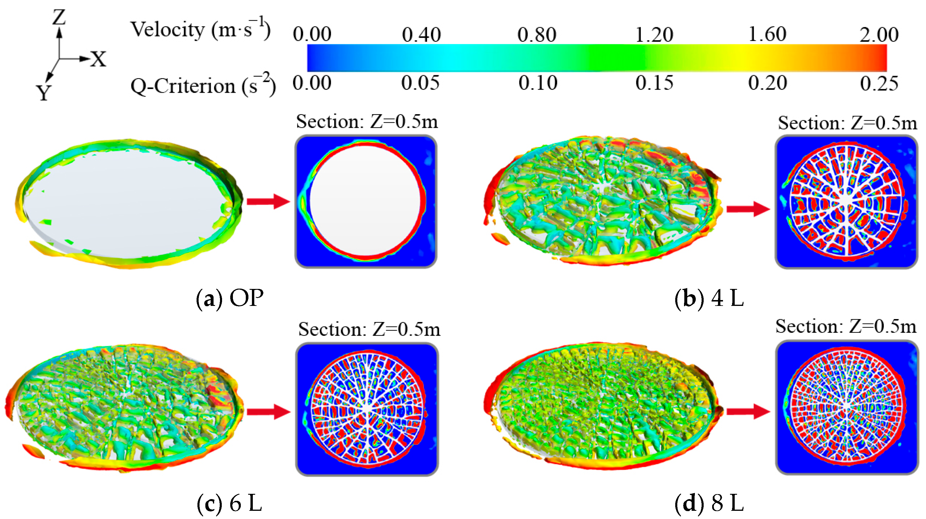
The energy dissipation mechanism of the fractal structure is further illustrated through the three-dimensional vortex distribution shown in Figure 17. The 3D vortex surfaces represent iso-surfaces of velocity magnitude, while the right-hand side displays a two-dimensional visualization of vortices within the fractal structure at the Z = 0.5 m cross-section. As depicted in the figure, the branching fractal structure, combined with the rib elements, forms numerous enclosed cavities. The fluid flowing within these cavities undergoes continuous changes in direction and velocity, giving rise to vortex generation.
When the Df corresponds to the 4 L configuration, vortices can form within the cavities; however, these vortices are too large for the cavities, preventing them from attaching effectively to the cavity walls, resulting in relatively low energy dissipation efficiency. As Df increases, the cavity scale decreases, enhancing the shear and centrifugal forces acting on the internal flow. This intensifies the viscous interaction with the cavity walls and facilitates vortex formation. When the Df reaches the 8 L configuration, large vortices within the cavity break down into multiple smaller vortices that come into full contact with the internal walls, strengthening fluid–structure interactions. This promotes more effective dissipation and absorption of wave energy, thereby improving the overall stability of the platform.
The stability improvement is driven primarily by viscous mechanisms—namely multiscale vortex generation and strengthened near-wall shear within the fractal cavities. As the branching level increases, coherent eddies break into smaller structures that remain attached to the cavity walls along a larger fraction of the perimeter. The resulting wall-bounded shear layers become broader and more persistent, and the cavities exhibit intensified small-scale rotational motion. In contrast, the pressure-drag pathway is localized: flow accelerates through narrow regions and decelerates within pocket regions, producing small stagnation and separation zones near rib leading edges. These pressure-drop features occupy a much smaller spatial extent and occur intermittently, whereas the high-shear regions are spatially extensive and repeat over the wave cycle. Overall, the evidence indicates that viscous, wall-bounded dissipation dominates, with pressure drag providing a secondary contribution.
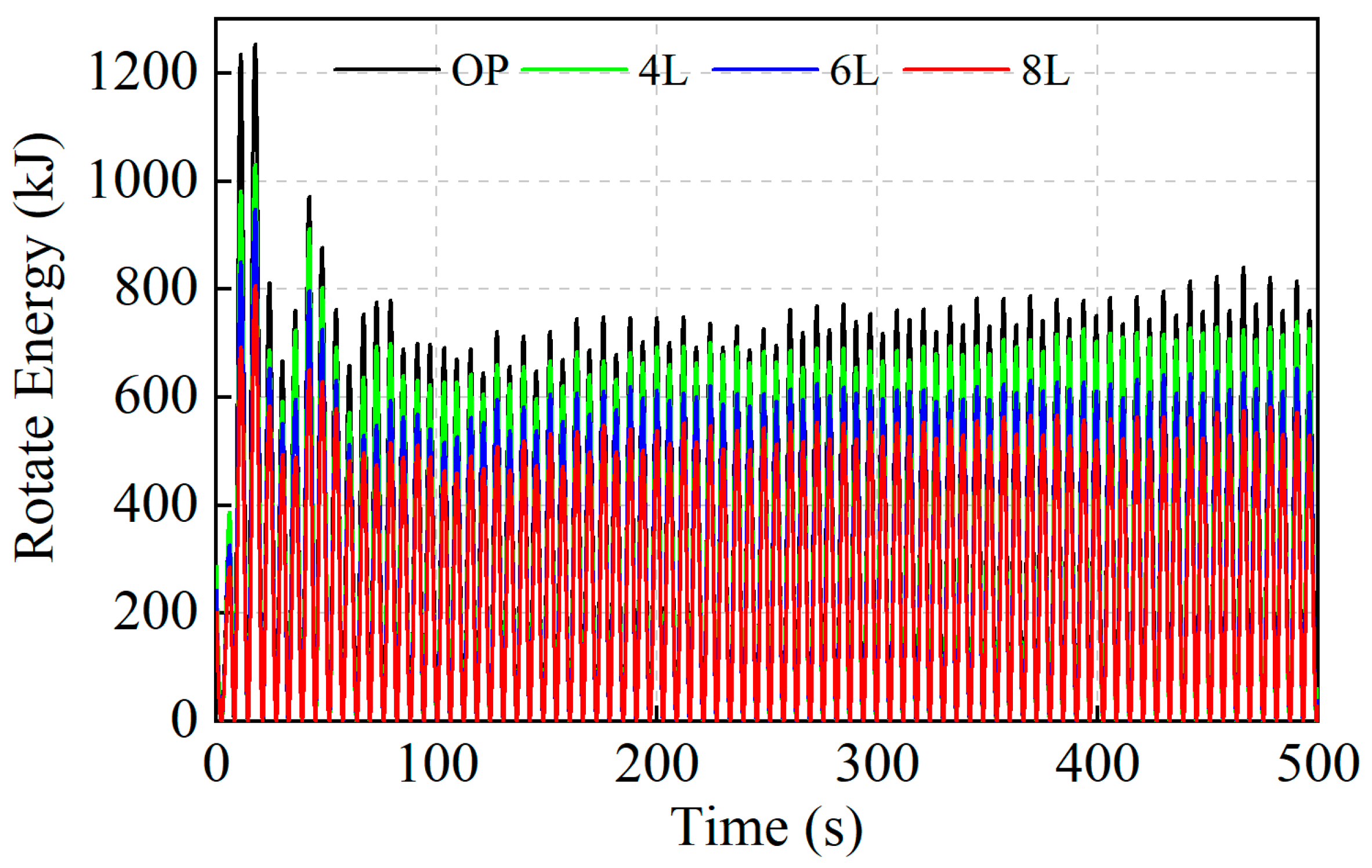
Rotational energy refers to the energy generated by a rigid body rotating about its center of mass and can be used to characterize the dynamic behavior during the platform’s rotational motion. Figure 18 presents the rotational energy response of the biomimetic platform.
As shown in Figure 18, the rotational energy amplitude of the bionic platforms is significantly lower than that of the original platform. Over the entire response duration, the maximum rotational energy amplitudes of the bionic platforms with fractal dimensions of 4 L, 6 L, and 8 L are 1031.58 kJ, 948.44 kJ, and 807.27 kJ, respectively—representing reductions of 17.72%, 24.38%, and 35.63% compared to the original platform (1253.98 kJ). During the five wave periods in the steady-state oscillation stage, the corresponding average rotational energies are 348.0 kJ, 303.3 kJ, and 265.2 kJ, showing decreases of 7.97%, 19.77%, and 29.86% relative to the original platform (378.1 kJ). In summary, both the average rotational energy and its amplitude decrease progressively with increasing fractal dimension, and the bionic platform with an 8 L fractal structure exhibits the best energy dissipation performance.

5. Effect of Fractal Height on Stability of Platform

5.1. Analysis of Hydrodynamic Performance

The 8 L fractal bionic platform was selected to investigate the influence of different bionic structure heights on platform performance. Three configurations with heights of 1 m, 2 m, and 3 m were considered, with corresponding platform masses of 12,982,368 kg, 12,498,270 kg, and 12,009,334 kg. The respective centers of gravity (below the waterline) are 13.168 m, 12.936 m, and 12.704 m. Compared to the OP, the bionic platforms exhibit mass reductions of 3.64%, 7.24%, and 10.87%, respectively. The detailed parameters are presented in Table 3.
Hydrodynamic performance calculations were conducted for the OP and the 8 L fractal bionic platforms with different structural heights under regular wave excitation, as shown in Figure 19.
As shown in Figure 19a, with the increase in fractal structure height, the overall mass of the semi-submersible platform gradually decreases while the draft increases, resulting in a downward shift in the heave response curves. When the fractal height reaches 3 m, the average heave offset of the bionic platform is the largest. During the initial 100 s of the response, the standard deviations of heave for the platforms with fractal heights of 1 m, 2 m, and 3 m are 0.878, 0.751, and 0.765, respectively, corresponding to reductions of 16.94%, 28.96%, and 27.61% compared to the OP (1.057). These results indicate that increasing the fractal height can significantly improve heave stability, with the 3 m configuration being the most effective in reducing vertical response.
Figure 19b shows that the pitch angle of the bionic platform decreases significantly as the fractal height increases. Over the entire response period, the maximum pitch angles for fractal heights of 1 m, 2 m, and 3 m are 1.98°, 1.27°, and 1.10°, respectively. Compared to the OP (2.58°), these represent reductions of 23.26%, 50.78%, and 57.36%, respectively, demonstrating that taller fractal structures can significantly enhance damping in the pitch direction and thus reduce platform pitching motion.
As shown in Figure 19c, all platforms experience a pronounced transient surge response during the initial stage (0–100 s), with peak surge displacements reaching up to 13 m. During this phase, the increase in fractal height does not exhibit a clear mitigating effect. After approximately 200 s, the surge responses of different configurations begin to converge, and their oscillation frequencies become nearly identical, indicating that fractal structure height has minimal influence on the dominant surge modes of the platform.
Although the overall surge trends are similar, slight variations in peak surge amplitudes can be observed with increasing fractal height. However, this influence is neither monotonic nor indicative of a consistent damping effect. This phenomenon is mainly attributed to the fact that surge motion is primarily governed by wave thrust and the waterline profile of the platform. Since the bionic fractal structures are located at the bottom of the pontoons, their influence on horizontal thrust resistance and wave diffraction is limited, making it difficult to provide substantial damping in the surge direction.
Figure 20 shows the velocity responses of the platforms with different fractal structure heights in the heave, pitch, and surge directions. As illustrated, the pitch velocity amplitude of the bionic platforms is reduced the most compared to the OP, followed by heave, while surge velocity exhibits no significant variation.
As shown in Figure 20a, the maximum absolute heave velocities for the bionic platforms with fractal heights of 1 m, 2 m, and 3 m are 0.869 m/s, 0.610 m/s, and 0.812 m/s, respectively—representing reductions of 21.00%, 44.55%, and 26.18% compared to the OP (1.10 m/s). During the initial stage (0–100 s), the OP exhibits the highest heave velocity amplitudes and the most intense fluctuations, indicating a strong vertical velocity shock induced by the initial wave impact. In contrast, the bionic platforms display clear vibration-suppressing characteristics, especially those with 2 m and 3 m fractal heights, where the velocity response quickly enters a stable state and the initial oscillation amplitude is significantly reduced. This demonstrates that the fractal structures help enhance the platform’s ability to suppress the initial excitation from wave impacts.
Figure 20b reveals that the OP also exhibits the highest and most fluctuating pitch velocity response, indicating a tendency toward pronounced angular acceleration and unstable rolling under wave excitation. In contrast, the bionic platforms demonstrate strong suppression of angular velocity. The average pitch angular velocities for fractal heights of 1 m, 2 m, and 3 m are 4.7744 × 10⁻⁵ rad/s, 4.0775 × 10⁻⁵ rad/s, and 3.1687 × 10⁻⁵ rad/s, respectively—representing reductions of 80.58%, 83.42%, and 87.11% compared to the OP (2.4587 × 10⁻⁴ rad/s). These results indicate that increasing the height of the fractal structure effectively enhances the fluid–structure interaction area at the platform’s base and improves the generation of shear vortices, thereby increasing viscous energy dissipation, reducing angular motion response, and improving the platform’s resistance to tilting.
Figure 20c shows that all platforms experience intense surge velocity spikes during the initial stage (0–100 s), with peak surge velocities approaching ±2 m/s. This indicates that the incoming wave exerts strong horizontal impact forces in the early phase. At this stage, the velocity responses of all platforms are nearly identical, with overlapping curves, suggesting that the influence of fractal height on surge velocity is minimal initially, and the response is still dominated by the platform’s overall inertia.
Figure 21 presents the mooring tension responses of ML1 and ML2 for both the bionic platforms and the OP. As shown in the figure, all platform configurations experience a distinct transient stretching phase during the initial period (approximately 0–100 s), characterized by a sharp rise in tension accompanied by intense oscillations. During this stage, the fractal structure height has minimal influence on the tension peak values, indicating that the transient response induced by the initial wave impact is still primarily governed by the platform’s overall inertia and wave excitation, with limited modulation capability from the bottom-mounted fractal structures.
As shown in Figure 21a, the tension response trends of the bionic platforms are generally consistent with that of the OP. However, with increasing fractal structure height, the average tension in ML1 decreases significantly. The maximum tension values for the 1 m, 2 m, and 3 m bionic configurations are 1553.634 kN, 1524.773 kN, and 1507.174 kN, respectively—representing reductions of 0.41%, 2.26%, and 3.39% compared to the OP (1560.106 kN). In contrast, the tension in ML2 remains largely consistent with the OP in both direction and magnitude during the steady-state phase.
Notably, the tension response trends of ML1 and ML2 are opposite to each other. ML 1 is anchored in the direction of wave propagation (positive X-direction), and thus it is stretched when the platform surges forward. ML2, on the other hand, is anchored in the opposite direction and experiences increased tension during the platform’s backward motion. This phase difference is closely related to the platform’s surge motion. The introduction of fractal structures enhances the flow field interaction at the base of the platform and the wave action points, thereby improving motion damping and indirectly reducing the dynamic response intensity of the mooring tensions.

5.2. Energy Dissipation Effects of Fractal Structures with Different Heights

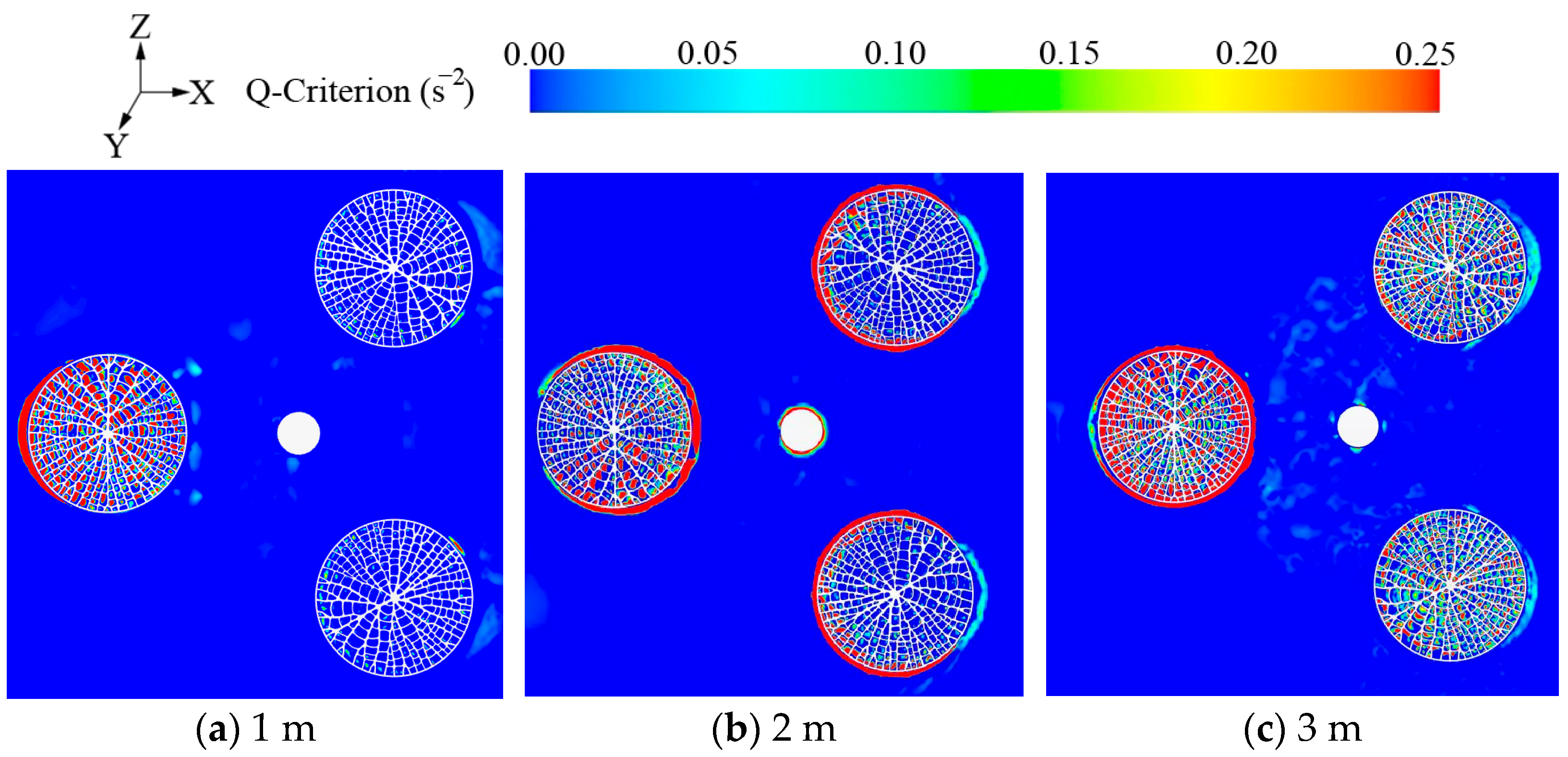
As shown in Figure 22, the flow fields at the Z = 0.5 m cross-section for platforms with three different bionic structure heights—1 m, 2 m, and 3 m—are visualized using the Q-Criterion at the mid-point of a wave cycle. A comparative analysis reveals that variations in structural height have a significant impact on the flow field configuration and local flow characteristics.
It can be observed from the figure that numerous high-Q regions are generated around the bionic-structured pontoons, especially under the 2 m and 3 m height conditions, where distinct red rings appear along the outer edge of the fractal structure, indicating a significant enhancement in vorticity intensity. This phenomenon arises from the wave-induced incoming flow being forced to deflect, shear, and contract upon encountering the bionic cavities, which leads to an increase in velocity gradients and the excitation of vortices. As the height of the bionic structure increases, the internal cavities become deeper and the structural surface area expands, thereby strengthening the fluid’s viscous effects and thickening the shear layers, which induce denser near-wall vortices. At a height of 3 m, the cavities are more refined, and the resulting vortex structures exhibit a multi-scale superimposed pattern characterized by smaller vortex cores and broader spatial distribution. This reflects the potential of taller bionic structures to enhance local flow disturbances, promote vortex breakdown, and facilitate kinetic energy dissipation.
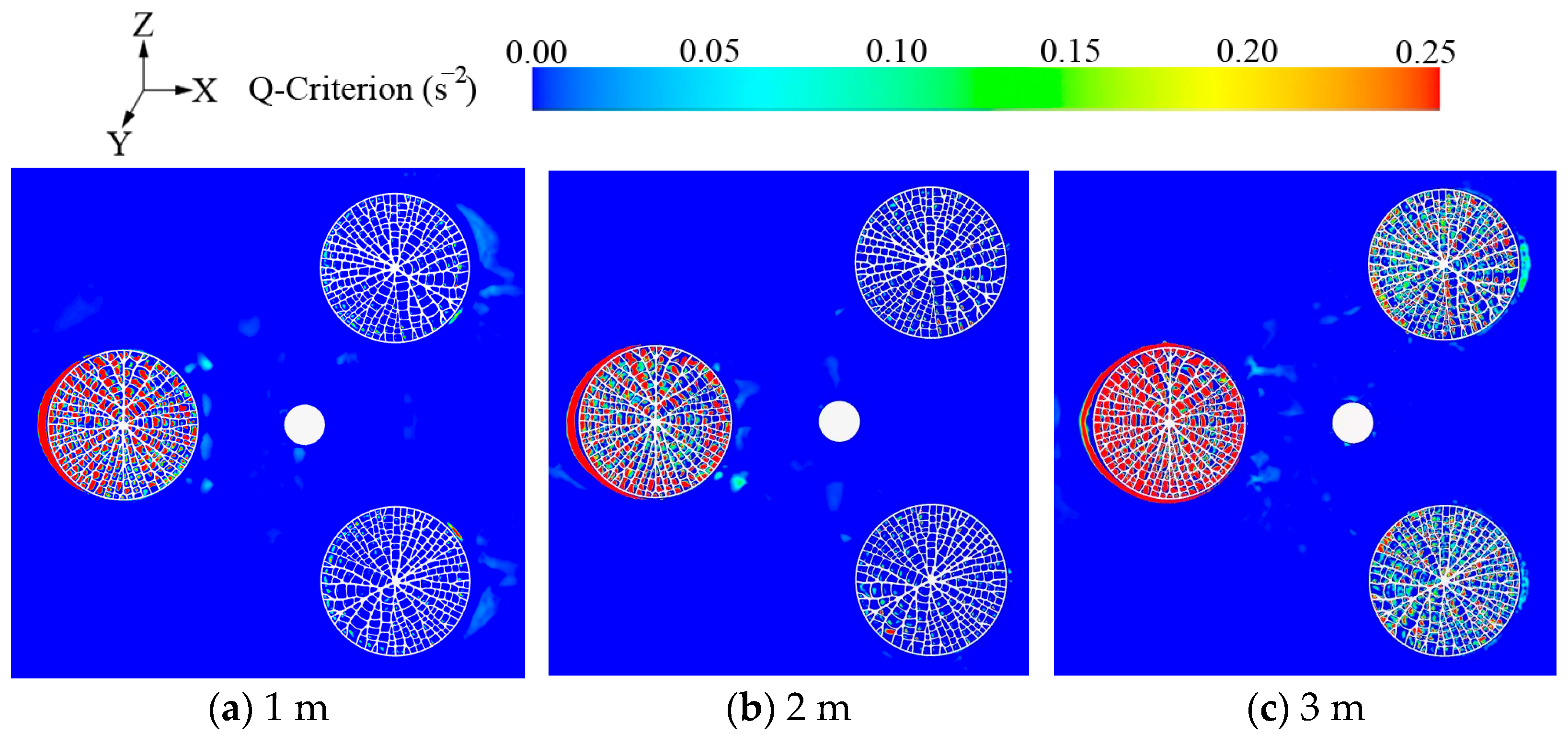
Figure 23 presents the Q-Criterion distribution at the Z = 0.5 m cross-section for platforms with bionic structures of 1 m, 2 m, and 3 m heights at the end of a complete wave period, aiming to visualize the vortex structures and analyze their energy dissipation characteristics.
At this stage, the platform has completed a full oscillation cycle, and the primary wave excitation has weakened. Therefore, the vortex structures shown in the figure mainly reflect the combined effects of inertial residual flow and structural disturbances. It can be observed that with the increase in the height of the fractal structure, the bionic platforms generate a broader range of high-Q regions inside the cavities and along the edges—especially at the 3 m height, where the vorticity distribution is more extensive and denser. This indicates that even after the wave excitation, the platform can maintain strong vortex structures and exhibit better flow disturbance persistence. Moreover, taller fractal cavities continue to exert traction and disturbance on the fluid during the wave decay phase, showing stronger vortex reconstruction and residual energy dissipation characteristics. Clearly the defined vortex bands near the cavity boundaries suggest significant interactions between wall shear flows and bypass vortices. In contrast, the Q-distribution of the 1 m high platform is more limited, with a more stabilized internal flow structure, indicating a diminished disturbance effect on the fluid by the end of the wave cycle. Overall, the results in the figure suggest that the higher the fractal structure, the more effective its energy dissipation at the tail end of the wave cycle. This not only enhances the platform’s fluid response control during primary excitation but also prolongs the dissipation process during wave retreat, effectively attenuating inertial residual responses and secondary oscillations.
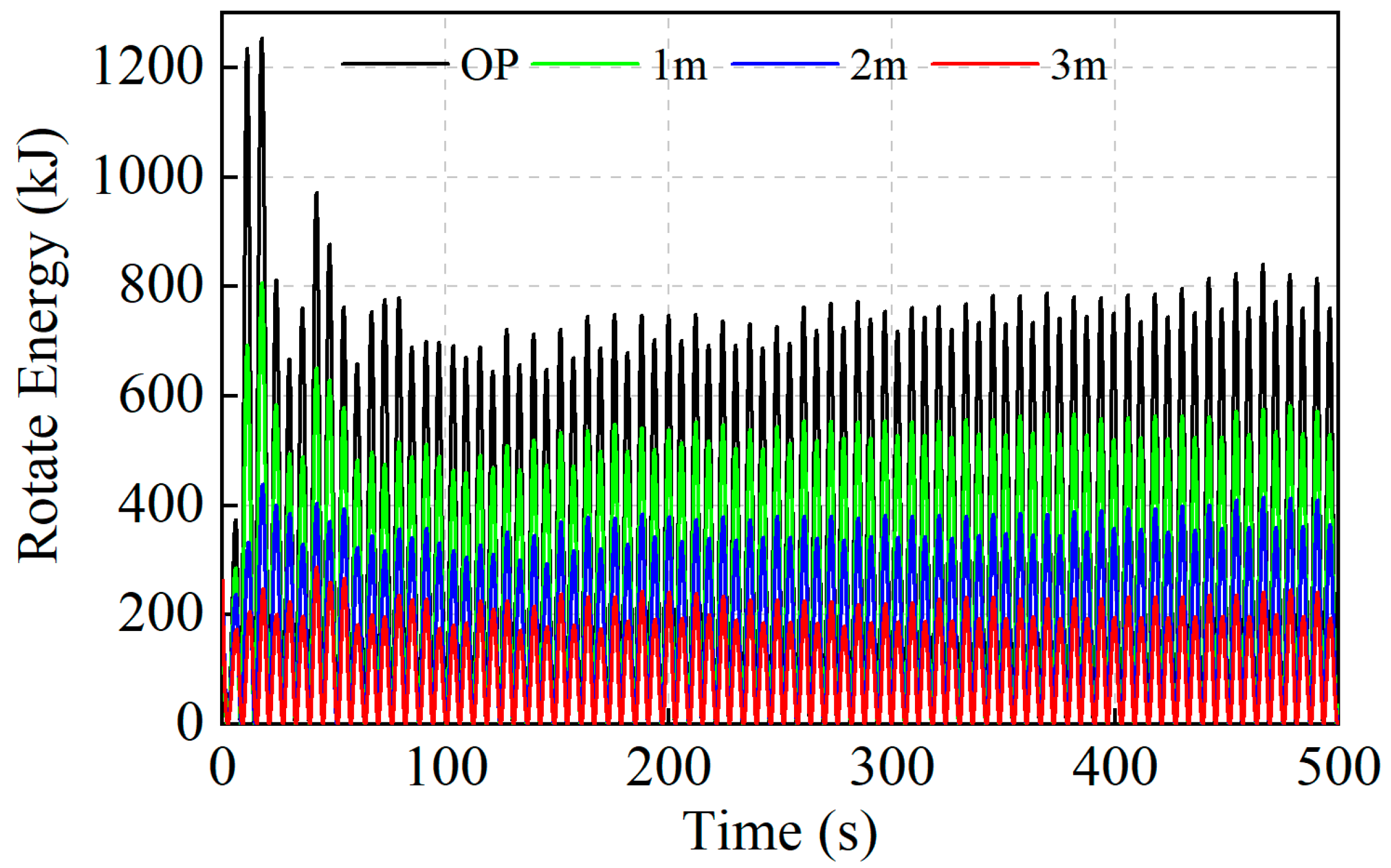
To evaluate the overall dynamic performance of the bionic platform under different fractal structure heights, the rotational energy generated by the platform’s rotation about its center of mass is introduced as a characterization indicator. Rotational energy not only reflects the magnitude of angular kinetic energy induced by wave excitation but also indirectly characterizes the restoring moment and disturbance resistance stability. Figure 24 illustrates the time history of rotational energy for the OP and the bionic platforms with fractal heights of 1 m, 2 m, and 3 m under regular wave excitation.
The results indicate that the original platform experienced severe rotational energy fluctuations during the initial stage, reaching a maximum of 1253.98 kJ. Although it later entered a stable oscillation phase, the overall energy level remained significantly higher than that of the bionic platforms. In contrast, the rotational energy of the bionic platforms exhibited a consistent decreasing trend with increasing fractal structure height. For fractal structure heights of 1 m, 2 m, and 3 m, the maximum rotational energy values were 807.27 kJ, 438.54 kJ, and 287.27 kJ, respectively, representing reductions of 35.62%, 65.03%, and 77.09% compared to the original platform. The corresponding average rotational energy values were 261.63 kJ, 175.97 kJ, and 102.15 kJ, which were 28.91%, 52.47%, and 72.24% lower than that of the original platform (368.09 kJ). These findings suggest that increasing the height of the fractal structure significantly enhances the platform’s hydrodynamic energy dissipation capacity. Specifically, during angular motion about the center of mass, the increased fluid–structure interaction area and intensified near-wall vortex effects effectively suppress the accumulation of rotational energy, thereby improving the platform’s overall stability and disturbance resistance.

6. Conclusions

In this study, a novel semi-submersible platform with a structure featuring fractal characteristics is proposed, inspired by the leaf-vein growth pattern of Victoria Amazonica, to enhance the hydrodynamic stability of a 5 MW floating offshore wind turbine (FOWT). The computational fluid dynamic (CFD) tool Star-CCM+, in conjunction with the dynamic fluid–body interaction (DFBI) method and the volume-of-fluid (VOF) model, is employed to investigate the dynamic responses of the FOWT system under varying fractal dimensions (Df) and structural heights. The primary conclusions are as follows:
(1)
The introduction of fractal structures significantly enhances the dynamic stability of the floating platform by increasing fluid–structure interactions and local energy dissipation. An increase in fractal complexity results in more effective wave energy absorption and a noticeable improvement in overall platform stability.
(2)
Among the different fractal complexities tested, the 8 L fractal structure demonstrated superior performance, effectively reducing heave, pitch, and rotational energy responses by 16.94%, 23.26%, and 35.63%, respectively, compared to the original platform.
(3)
Increasing the height of the fractal structures further improves the hydrodynamic performance of the platform, notably enhancing stability in the pitch direction due to intensified local vortex formation and strengthened shear interactions within the fractal cavities.
(4)
At the highest structure height (3 m), the fractal cavities exhibit pronounced vortex refinement and enhanced viscous dissipation effects, resulting in maximum energy absorption and significant suppression of wave-induced platform motions.
(5)
The structure exhibits self-similarity and modularity, making it suitable both for built-in designs of new platforms and for modular retrofits of platforms in service. It can be fabricated either through standardized plate–stiffener segmented manufacturing with on-site assembly or via large-scale additive manufacturing. This approach holds significant promise for the future design and application of floating offshore wind turbine platforms.

7. Future Work

In this study, only four-, six-, and eight-level leaf-vein fractal structures were analyzed, and in the future, the optimal branch levels could be determined using a multi-objective optimization algorithm based on the comprehensive consideration of the structure size, quality, and number of branches. To isolate the influence of the biomimetic fractal structural features on the platform while controlling computational cost, we adopted a simplified model; in future work, we will employ fully coupled simulations to further refine and complete the analysis. Going forward, we will actively overcome experimental constraints and conduct scaled wave-basin tests to provide direct experimental validation and further strengthen the reliability of our conclusions.

Author Contributions

W.Z. (Wanyong Zhang): Conceptualization, Methodology, Investigation, Software, Validation, Data curation, Writing—original draft. H.H.: Conceptualization, Formal analysis, Writing—review and editing. Q.L.: Investigation, Resources, Data curation, Writing—review and editing, Supervision. Y.Y.: Investigation, Resources, Writing—review and editing, Supervision. C.L.: Supervision, Resources, Funding acquisition, Project administration. W.M.: Investigation, Resources, Supervision, Funding acquisition. M.Y.: Conceptualization, Formal analysis, Funding acquisition. W.Z. (Wanfu Zhang): Investigation, Software, Validation. All authors have read and agreed to the published version of the manuscript.

Funding

This research was funded by the National Natural Science Foundation of China (grand No. 52476212, 52376204) and the Shanghai Science and Technology Development Foundation (grand No. 24ZR1454800).

Data Availability Statement

The original contributions presented in this study are included in the article. Further inquiries can be directed to the corresponding authors.

Conflicts of Interest

The authors declare that they have no known competing financial interests or personal relationships that could have appeared to influence the work reported in this paper.

Abbreviations

The following abbreviations are used in this manuscript:
FOWTsFloating offshore wind turbines
CFDComputational fluid dynamic
DFBIDynamic fluid–body interaction
VOFVolume-of-fluid
MLMooring line
SWLStill water level
DfFractal dimension
OPOriginal platform
LVFSLeaf-vein fractal structure

References

  1. Liu, S.; Zhang, L.; Lu, J.; Zhang, X.; Wang, K.; Gan, Z.; Liu, X.; Jing, Z.; Cui, X.; Wang, H. Advances in urban wind resource development and wind energy harvesters. Renew. Sustain. Energy Rev. 2025, 207, 114943. [Google Scholar] [CrossRef]
  2. Koragappa, P.; Verdin, P.G. Design and optimisation of a 20 MW offshore wind turbine blade. Ocean. Eng. 2024, 305, 117975. [Google Scholar] [CrossRef]
  3. Xu, Z.; Zhao, K.; Wang, J.; Bashir, M. Physics-informed probabilistic deep network with interpretable mechanism for trustworthy mechanical fault diagnosis. Adv. Eng. Inform. 2024, 62, 102806. [Google Scholar] [CrossRef]
  4. Alkhalidi, A.; Kaylani, H.; Alawawdeh, N. Technology assessment of offshore wind turbines: Floating platforms—Validated by case study. Results Eng. 2023, 17, 100831. [Google Scholar] [CrossRef]
  5. Liu, Q.S.; Miao, W.P.; Li, C.; Hao, W.; Zhu, H.; Deng, Y. Effects of trailing-edge movable flap on aerodynamic performance and noise characteristics of VAWT. Energy 2019, 190, 116271. [Google Scholar] [CrossRef]
  6. Butterfield, S.; Musial, W.; Jonkman, J.M.; Sclavounos, P. Engineering Challenges for Floating Offshore Wind Turbines; National Renewable Energy Lab.: Golden, CO, USA, 2007. [Google Scholar]
  7. Edwards, E.C.; Holcombe, A.; Brown, S.; Ransley, E.; Hann, M.; Greaves, D. Evolution of floating offshore wind platforms: A review of at-sea devices. Renew. Sustain. Energy Rev. 2023, 183, 113416. [Google Scholar] [CrossRef]
  8. Huang, H.; Liu, Q.; Bashir, M.; Malkeson, S.; Li, C.; Yue, M.; Miao, W.; Wang, J. Dynamic performance optimization of a floating offshore wind turbine based on fractal-inspired design principles. Energy 2025, 324, 135963. [Google Scholar] [CrossRef]
  9. Muliawan, M.J.; Karimirad, M.; Gao, Z.; Moan, T. Extreme responses of a combined spar-type floating wind turbine and floating wave energy converter (STC) system with survival modes. Ocean. Eng. 2013, 65, 71–82. [Google Scholar] [CrossRef]
  10. Wang, X.Q.; Zhang, Z.H.; Zhuge, P. Transient analysis of a novel full submersible floating offshore wind turbine with CFRP tendons. Ocean. Eng. 2022, 266, 112686. [Google Scholar] [CrossRef]
  11. Zou, Q.; Lu, Z.Y.; Shen, Y.J. Short-term prediction of hydrodynamic response of a novel semi-submersible FOWT platform under wind, current and wave loads. Ocean. Eng. 2023, 278, 114471. [Google Scholar] [CrossRef]
  12. Feng, X.H.; Lin, Y.G.; Gu, Y.J.; Li, D.; Chen, B.; Liu, H.; Sun, Y. Preliminary stability design method and hybrid experimental validation of a floating platform for 10 MW wind turbine. Ocean. Eng. 2023, 285, 115401. [Google Scholar] [CrossRef]
  13. Zhang, H.J.; Wang, H.; Cai, X.; Zhang, H.; Wang, H.; Cai, X.; Xie, J.; Wang, Y.; Zhang, N. Novel method for designing and optimising the floating platforms of offshore wind turbines. Ocean. Eng. 2022, 266, 112781. [Google Scholar] [CrossRef]
  14. Cutler, J.; Bashir, M.; Yang, Y.; Wang, J.; Loughney, S. Preliminary development of a novel catamaran floating offshore wind turbine platform and assessment of dynamic behaviours for intermediate water depth application. Ocean. Eng. 2022, 258, 111769. [Google Scholar] [CrossRef]
  15. Yang, J.; He, Y.P.; Zhao, Y.S.; Yang, X.Y.; Zhang, G.R. Coupled dynamic response analysis of multi-column floating offshore wind turbine with low center of gravity. J. Ocean. Eng. Sci. 2024, 9, 25–39. [Google Scholar] [CrossRef]
  16. Edwards, E.C.; Holcombe, A.; Brown, S.; Ransley, E.; Hann, M.; Greaves, D. Trends in floating offshore wind platforms: A review of early-stage devices. Renew. Sustain. Energy Rev. 2024, 193, 114271. [Google Scholar] [CrossRef]
  17. Mandelbrot, B. How long is the coast of Britain? Statistical self-similarity and fractional dimension. Science 1967, 156, 636–638. [Google Scholar] [CrossRef] [PubMed]
  18. Carl, B. Fractal Geometry in Architecture and Design. Nexus Netw. J. 1996, 3, 145–146. [Google Scholar]
  19. Wu, J.C.; Zhang, Y.; Zhang, F.; Hou, Y.; Yan, X. A bionic tree-liked fractal structure as energy absorber under axial loading. Eng. Struct. 2021, 245, 112914. [Google Scholar] [CrossRef]
  20. Bogahawaththa, M.; Mohotti, D.; Hazell, P.J.; Wang, H.; Wijesooriya, K.; Lee, C.K. Low-velocity impact response and energy absorption of Menger sponge-inspired fractal structures fabricated by selective laser melting. Eng. Struct. 2024, 321, 118955. [Google Scholar] [CrossRef]
  21. Zheng, Y.; Lu, Y.; Hou, Y.; Ke, J. Design and mechanical performance analysis of a novel bionic lattice structure. Mater. Today Commun. 2024, 41, 110409. [Google Scholar] [CrossRef]
  22. Zhang, H.K.; Zhou, J.; Fang, W.; Zhao, H.; Zhao, Z.L.; Chen, X.; Zhao, H.P.; Feng, X.Q. Multi-functional topology optimization of Victoria cruziana veins. J. R. Soc. Interface 2022, 19, 20220298. [Google Scholar] [CrossRef]
  23. Robertson, A.; Jonkman, J.; Masciola, M.; Song, H.; Goupee, A.; Coulling, A.; Luan, C. Definition of the Semisubmersible Floating System for Phase II of OC4; USDOE Office of Energy Efficiency and Renewable Energy Wind Power Technologies Office: Golden, CO, USA, 2014. [Google Scholar]
  24. Rian, L.M. Random fractal-based computational design of an ice-ray (IR) lattice shell structure. Front. Archit. Res. 2024, 13, 406–424. [Google Scholar] [CrossRef]
  25. Choi, J.; Yoon, S.B. Numerical simulations using momentum source wave-maker applied to RANS equation model. Coast. Eng. 2009, 56, 1043–1060. [Google Scholar] [CrossRef]
  26. Sudharsun, G.; Ali, A.; Mitra, A.; Jaiswal, A.; Naresh, P.; Warrior, H. Free surface features of submarines moving underwater: Study of Bernoulli Hump. Ocean. Eng. 2022, 249, 110792. [Google Scholar]
  27. Leonard, B.P. Bounded higher-order upwind multidimensional finite volume convection-diffusion algorithms. Comput. Methods Appl. Mech. Eng. 1997, 1–57. [Google Scholar]
  28. Tran, T.T.; Kim, D.H. Fully coupled aero-hydrodynamic analysis of a semi-submersible FOWT using a dynamic fluid body interaction approach. Renew. Energy 2016, 92, 244–261. [Google Scholar] [CrossRef]
  29. Luan, C.; Gao, Z.; Moan, T. Modelling and Analysis of a Semi-Submersible Wind Turbine with a Central Tower with Emphasis on the Brace System. In Proceedings of the ASME 2013 32nd International Conference on Ocean, Offshore and Arctic Engineering, Nantes, France, 14–19 June 2013. [Google Scholar]
Figure 1. Leaf-vein fractal structure (LVFS) of Victoria Amazonica.
Jmse 13 01708 g001
Figure 2. Parametric modeling of branch fractal structure.
Jmse 13 01708 g002
Figure 3. Novel biomimetic platform with different fractal dimensions.
Jmse 13 01708 g003
Figure 4. Real-scale model of OC4 semi-submersible FOWT.
Jmse 13 01708 g004
Figure 5. Box-counting method.
Jmse 13 01708 g005
Figure 6. Df under different branch levels.
Jmse 13 01708 g006
Figure 7. Boundary conditions of real-scale model.
Jmse 13 01708 g007
Figure 8. Mesh division of numerical model.
Jmse 13 01708 g008
Figure 9. Mesh independence verification.
Jmse 13 01708 g009
Figure 10. Free decay results [22].
Jmse 13 01708 g010
Figure 11. Natural period results [22,23].
Jmse 13 01708 g011
Figure 12. Dynamic results of the biomimetic fractal platforms.
Jmse 13 01708 g012
Figure 13. Velocity response results of biomimetic fractal platforms.
Jmse 13 01708 g013
Figure 14. Mooring tension response results of biomimetic fractal platforms.
Jmse 13 01708 g014
Figure 15. Average amplitude and standard deviation of dynamic response.
Jmse 13 01708 g015
Figure 16. Velocity distribution at Z = 0.5 m section.
Jmse 13 01708 g016
Figure 17. Vortex distribution in biomimetic fractal structure.
Jmse 13 01708 g017
Figure 18. Rotational energy response results of biomimetic fractal platform.
Jmse 13 01708 g018
Figure 19. Dynamic results of the biomimetic fractal platforms.
Jmse 13 01708 g019
Figure 20. Velocity response results of biomimetic fractal platforms.
Jmse 13 01708 g020
Figure 21. Mooring tension response results of biomimetic fractal platforms.
Jmse 13 01708 g021
Figure 22. Velocity distribution at mid-section of biomimetic fractal structures at mid-period of wave.
Jmse 13 01708 g022
Figure 23. Velocity distribution at mid-section of biomimetic fractal structures at the end of the wave period.
Jmse 13 01708 g023
Figure 24. Rotational energy response results of biomimetic fractal platform.
Jmse 13 01708 g024
Table 1. OC4 platform specifications.
PropertiesUnitValue
Total masskg13,473,000
CM height below still water level (SWL)m13.46
Inertia moment (Mx)kg·m26.827 × 109
Inertia moment (My)kg·m26.827 × 109
Inertia moment (Mz)kg·m21.226 × 1010
Table 2. Parameters of the original and fractal bionic platforms.
ObjectsTotal Mass (kg)CM Below the SWL (m)Mx (kg·m2)My (kg·m2)Mz (kg·m2)
OP13,473,42113.4606.557 × 1096.557 × 1091.172 × 1010
4 L12,642,79713.0166.141 × 1096.141 × 1091.096 × 1010
6 L12,803,74213.0986.221 × 1096.221 × 1091.111 × 1010
8 L12,982,36813.1686.307 × 1096.307 × 1091.127 × 1010
Table 3. Parameters of the OP and 8 L fractal bionic platforms with different heights.
ObjectsTotal Mass (kg)CM Below the SWL (m)Mx (kg·m2)My (kg·m2)Mz (kg·m2)
OP13,473,42113.4606.557 × 1096.557 × 1091.172 × 1010
1 m12,982,36813.1686.307 × 1096.307 × 1091.127 × 1010
2 m12,498,27012.9366.066 × 1096.066 × 1091.082 × 1010
3 m12,009,33412.7045.827 × 1095.827 × 1091.038 × 1010
Disclaimer/Publisher’s Note: The statements, opinions and data contained in all publications are solely those of the individual author(s) and contributor(s) and not of MDPI and/or the editor(s). MDPI and/or the editor(s) disclaim responsibility for any injury to people or property resulting from any ideas, methods, instructions or products referred to in the content.