Review

Multi-Branch Towed Array System: Systematic Analysis of Modeling Methods, Environmental Responses and Mechanical Properties in Fracture Analysis

1
Ship and Maritime College, Guangdong Ocean University, Zhanjiang 524005, China
2
Guangdong Provincial Key Laboratory of Intelligent Equipment for South China Sea Marine Ranching, Guangdong Ocean University, Zhanjiang 524088, China
3
School of Electronics and Information Engineering, Guangdong Ocean University, Zhanjiang 524088, China
4
Faculty of Maritime and Transportation, Ningbo University, Ningbo 315211, China
*
Author to whom correspondence should be addressed.
J. Mar. Sci. Eng. 2025, 13(9), 1697; https://doi.org/10.3390/jmse13091697
Submission received: 20 July 2025 / Revised: 18 August 2025 / Accepted: 28 August 2025 / Published: 2 September 2025

Abstract

Multi-branch towed array systems are an important component of subsea information collection, which is increasingly required for subsea pipeline laying and offshore platform construction as ocean energy is exploited. However, the complexity of underwater conditions poses challenges for marine towing systems when collecting information, including the possibility of towing cable collisions with protruding seabed or submerged organisms during towing system travel, or towing cable interactions during torsion. These collisions can affect and interfere with the collection of information by the towing system, and can cause damage to the towing system or even cause the towing cable to break. After the failure and detachment of the outboard guide cable of a multi-branch towing cable array, the formation of the towing system changes, and these changes are complex and related to the prevailing sea state. To study the important condition of the damaged towing system, this paper draws an analogy between the towing system and the trawl net, and speculates the formation change and mechanical response of the multi-branch towed array system after damage by combining the influencing factors of the deployment of the towing system.

1. Introduction

With the rapid progress of modern submarine silencing technology [1,2,3,4,5,6], anti-submarine warfare has posed unprecedented challenges to the performance of underwater detection systems. Towed Array Sonar (TAS) [7,8,9] has become the core equipment for military anti-submarine and marine resources exploration because it can move the acoustic receiving unit away from the mother ship to realize long-distance and high-precision underwater target detection [10,11,12]. In addition, it has also been applied in the seabed topography exploration [13,14], marine environment monitoring, marine rescue, marine life protection, marine resources exploration and underwater archaeology. In addition, in seabed terrain exploration, marine environment monitoring, marine rescue, marine life protection, marine resources exploration and underwater archaeology, towed line array has also been applied [15,16,17,18,19,20,21,22]. Among them, the Multi-branch Towed Acoustic Array System (MBTAAS) effectively solves the port and starboard fuzzy problem of the traditional single-line array by laying multiple spatially separated towing cables in parallel, which significantly enhances the target orientation capability and detection coverage [9,23,24,25,26]. The system usually consists of the aft leading cable, the air gun energy transfer cable and the main cable of the aft towed acoustic array, while the outboard guiding cable, as a key component to maintain the overall spatial configuration, prevents entanglement and collision of the towed cables under complex sea conditions by restraining their relative positions, which guarantees the geometric integrity and functional stability of the acoustic array [27]. The system has been designed to provide the most effective and efficient way to provide the most suitable protection for the acoustic array to ensure target detection.
In engineering practice, all tools and structures are subject to damage. These damages often need to be monitored in real time to avoid irreversible damage to the building or tool [28,29,30,31,32,33,34,35]. Similarly, damage can occur to the sideboard cables of multibranch line arrays. A break in the outboard guiding cable during towline travel can result in loss of support for the towline, causing the towline system’s trajectory to become unrestricted and the course and equilibrium of the towline system to be altered. In order to avoid this extreme phenomenon. Researchers tend to focus more on fatigue monitoring of towing cables to avoid breakage. However, few researchers pay attention to the mechanical response and formation changes after the towline breaks. Monitoring of the towline can minimize accidents, and fracture research is as important as detection, because special conditions at sea are unavoidable. The re-stabilization process after the breakage of outboard guiding cables and towing cables also involves mechanical response and attitude control, so the process analysis of towline formation and towline steady state can be used to analyze and summarize the phenomenon of towing system breakage to a certain extent. Existing studies mostly focus on the overall morphological changes of the tow cable after breakage, but do not clearly define the specific location of the breakage. For breaks at different positions, there are significant differences in the mechanical transfer path and the degree of system instability. For example, the connection point between the guide cable and the main cable is prone to becoming a stress concentration area as it needs to bear both the axial tension of the main cable and the lateral restraint force of the guide cable. In the middle part of the guide cable, the influence of ocean current vortex-induced vibration is more significant, and the risk of breakage increases with the degree of coupling between the vortex street frequency and the natural frequency of the guide cable. Therefore, clarifying the definition and causes of the breakage location is a prerequisite for accurately analyzing the dynamic response of the system.
In order to study the phenomenon of sideboard cable breakage, the multi-branch line array and the tugboat are modeled in this paper and the control equations and mechanical analysis equations are given, and the model is used to simulate the sideboard’s unilateral or bilateral guided cable breakage in different sea states, and the results of the formation change when the outboard guide cable fails and detaches are obtained. Subsequently, in order to study the mechanical response and the factors affecting the towline take-up, the influencing factors during towline deployment are analyzed, and we analyze the trawl net during the trawling period, which also has no sideboard guide cable, so as to speculate the influencing factors and mechanical response during the towing period. Finally, this paper analyzes the mechanical response of the towline in different states and sea states to analyze the phenomena that may arise in case of breakage. This paper adds to the direction of towline array bunching in the field of towing cables, and has a certain guiding effect in this field.

2. Cable Discrete Theory and Modeling Basics

2.1. Model Building

During the simulation, the towing speed of the tugboat is always 2 m/s and the direction is always to the right. In the simulation, the horizontal direction to the right is the X-axis positive direction, the direction obtained by rotating the X-axis positive direction counterclockwise by 90° in the horizontal plane is the Y-axis positive direction, and the direction of the vertical horizontal plane upward is the Z-axis positive direction, as shown in Figure 1.

2.2. Control Equations for Towing Cable Motion

Three coordinate systems are established to describe the motion of the whole system, inertial coordinate system ( x y z ) , towing cable local coordinate system ( b t n ) and towing body motion coordinate system ( ξ η ζ ) . The origin of the inertial coordinate system is located at the water surface, and the z -axis is vertically upward; the local coordinate system of the towing cable is attached to the towing cable, and the t -axis is the tangential direction of the cable, the n -axis is the normal direction, and the b -axis is the side-normal direction; and the coordinate system of the motion of the towing body follows the towing body’s motion, with the ξ -axis pointing to the bow, the η -axis pointing to the starboard side, and the ζ -axis pointing to the bottom. These three coordinate systems are related to each other by the attitude angle, and the transformation relationship is as follows:
x y z = A b t n = Q ξ η ζ
where A is the towing cable coordinate system transformation matrix
A = cos θ sin θ cos ϕ sin θ sin ϕ sin θ cos θ cos ϕ cos θ sin ϕ 0 sin ϕ cos ϕ
where Euler’s angle θ, the attitude angle of the towing cable in the inertial coordinate system, depends only on the spatial location of the cable, and its value range is set as
θ ( 180 , 180 ] ϕ 90 , 90
According to the idea of centralized mass method, a tow cable is discretized into N segments, i.e., N + 1 nodes, from the tail end to the top end, where the tail end s = 0 is the i = 0 th node and the top end s = S is the i = N th node.
Applying Newton’s second law to the i th node yields the basic equations of motion for the towing cable node
M i x ¨ i = F i
where: x is its spatial position vector, x ¨ is the acceleration; M i is the mass matrix, including the inertial mass of the towline node itself and its additional mass in the water M a , i
M i = 0.5 ( μ i 1 / 2 l i 1 / 2 + μ i + 1 / 2 l i + 1 / 2 ) I + M a , i
M a , i = 0.5 ( M a , i 1 / 2 + M a , i + 1 / 2 )
M a = ρ l σ 1 sin 2 θ cos 2 ϕ cos θ sin θ cos 2 ϕ sin θ cos ϕ sin ϕ cos θ sin θ cos 2 ϕ 1 cos 2 θ cos 2 ϕ cos θ cos ϕ sin ϕ sin θ cos ϕ sin ϕ cos θ cos ϕ sin ϕ cos 2 ϕ
I is a 3 × 3 unit matrix; μ , l , σ are the mass per unit length of the tow cable, the length between nodes, and the cross-sectional area, respectively; the subscript i + 1 / 2 denotes the physical quantity between node i and node i + 1 , e.g., l i + 1 / 2 denotes the length between node i and node i + 1 , i.e., l i + 1 / 2 . For simplicity, some subscripts in subsequent formulas will be omitted unless specified otherwise.
F i are all the forces acting on the node i , including the basic towline tension, buoyancy, gravity, and fluid resistance, and if there are other external forces on the towline, they should be included.
F i = Δ T i + B i + G i + D i
(1)
Tension T in general the strain of the cable ε i 1 , the stress–strain relationship can be elastically treated.
Δ T i = T i + 1 / 2 T i 1 / 2 T i + 1 / 2 = E σ ε i + 1 / 2 τ i + 1 / 2 ε i + 1 / 2 = ( x i + 1 x i ) 2 + ( y i + 1 y i ) 2 + ( z i + 1 z i ) 2 / l i + 1 / 2 1
where: τ is the unit tangent vector in the direction of the cable length; E is the modulus of elasticity. The same reason can be obtained T i 1 / 2 taking into account the tension and compression elastic properties of the towing cable is different, in this paper the towing cable under pressure (strain is negative) when the modulus of elasticity is taken as an approximation for the tensile 1/10.
(2)
Buoyancy B and gravity G , the buoyancy and gravity of node i can be expressed as
B i + G i = 0.5 ρ ( l i 1 / 2 σ i 1 / 2 + l i + 1 / 2 σ i + 1 / 2 ) g + 0.5 ( μ i 1 / 2 l i 1 / 2 + μ i + 1 / 2 l i + 1 / 2 ) g
where g is the acceleration of gravity.
(3)
Fluid resistance D The dragline resistance is divided into tangential and normal directions and can be expressed after accounting for the effect of cable strain as follows
D i = 0.5 ( D i + 1 / 2 + D i 1 / 2 )
D 0.5 ρ l d 1 + ε ( C n | x ˙ n b | x ˙ n b + π C t x ˙ t x ˙ t )
where: x ˙ is the velocity vector of the node; d is the diameter of the cable; C n , C t are the normal and tangential drag coefficients, respectively.
We then give the boundary conditions for the free ends of the towing cable, and for the free ends without the towing body (cables B, C), which are treated as one node, we apply the centralized mass method directly.
M 0 x ¨ 0 = F 0
M 0 = 0.5 ( μ 1 / 2 l 1 / 2 I + M a .1 / 2 ) ; F 0 = T 1 / 2 + 0.5 ( ρ 1 / 2 σ 1 / 2 + μ 1 / 2 l 1 / 2 ) g + 0.5 D 1 / 2 .
This gives the basic control equations for each towing cable
d x ˙ i d t = M i 1 F i d x i d t = x ˙ i i = 0 , 1 , , N 1
Towline breakage or outboard breakage will have a very complex situation on the steady state of the towline array and the mechanical response of the towline. The above relatively simple equations for controlling the motion of the towline can simplify the difficulty of controlling the towline, and can roughly describe the motion of the towline and the equilibrium process of rebalance of the towline array after the towline or the outboard guiding cable breaks.

2.3. Mechanical Equations for Towing Cables

In Yang’s study, they also divided the cable into N + 1 nodes and in their experiments, they obtained that the forces acting on the nodes on the towing cable originate from the forces acting on the neighboring units.
G n o d e 1 F n o d e 1 d t F n o d e 1 d n G n o d e 2 F n o d e 2 d t F n o d e 2 d n G n o d e n F n o d e n d t F n o d e n d n n × 3 = 1 2 0 0 0 1 2 1 2 0 0 0 0 0 1 2 n × ( n 1 ) × G e l e 1 F e l e 1 d t F e l e 1 d n G e l e 2 F e l e 2 d t F e l e 2 d n G e l e n 1 F e l e n 1 d t F e l e n 1 d n ( n 1 ) × 3
Here G n o d e n , F n o d e n d t and F n o d e n d n are the gravitational, tangential and normal resistance forces acting on node i, respectively. Further G e l e n 1 , F e l e n 1 d t and F e l e n 1 d n are the gravitational, tangential and normal resistance forces acting on cell I, respectively [36].
In their experiments, they also obtained a mechanical relationship between i − 1 and i.
F { i 1 , i } + 1 2 F e l e i 1 d t + 1 2 F e l e i 1 d n + 1 2 G e l e i 1 + 1 2 F e l e i d t + 1 2 F e l e i d n + 1 2 G e l e i + F { i , i + 1 } = 0
where F { i 1 , i } is the spring force between node i and node i − 1
The control equations for each point of the tow cable in the towline array were also obtained in Yang’s experiments, the mathematical relationships of which can be found in [37].
x n x n + 1 ρ a δ r r ¨ d x = δ q α F k α + δ w W k
In addition to this, they added general elastic forces, Morison’s forces and gravity vectors at points on the towing cable [38].
( F e α ) n = V n q α = k n ε ¯ α β μ v Q μ v + k n κ α β μ v Q ˜ μ υ q β
F m α n = δ W n δ q n = x n x n + 1 n α sgn π 2 ρ f C f D ( v i ) 2 i + 1 2 ρ f C d D P v P v + ρ f 1 + C m π D 2 4 P U ˙ ρ f C m π D 2 4 P r ¯ d x
F g α n = x n x n + 1 n α ρ w g d x
They presented the equation for the absorption of waves by a tow cable [39].
η t + φ ˜ x η x 1 + η x 2 w + μ η = 0 φ ˜ t + 1 2 ( φ ˜ x ) 2 + g η 1 2 1 + η x 2 w 2 + μ φ ˜ = 0
Then, they obtained the discrete equation for the towing cable after accounting for wave effects.
F 1 α = Γ n F S N x β N x μ d x φ ˜ β η μ Γ n F S 1 + η π 2 η + h N α N β d x w ^ β + Γ n F S μ x N α N β d x η β
F 2 α = 1 2 Γ n F S N α N x β N x μ d x φ ˜ β φ ˜ μ g Γ n F S N α N β d x η β + 1 2 Γ n F S 1 + η z 2 η + h 2 N α N β N μ d x w ^ β w ^ μ + Γ n F S μ x N α N β d x φ ˜ β

2.4. Other Common Types of Discrete Methods for Towing Cables

Based on the derivation of the control equations and mechanical equations of the tow cable motion, this section focuses on the key technical aspect of the discretization method of the tow cable, systematically introducing various commonly used discretization methods including the Cosserat rod model, semicontinuous model, lumped mass method, absolute nodal coordinates model and finite difference method (see Table 1). The aim is to provide a theoretical basis for selecting appropriate modeling methods according to specific scenarios in subsequent research, while also laying the methodological foundation for in-depth analysis of the dynamic response of the tow cable under special conditions such as breakage.

2.4.1. Cosserat Rod Model

In the field of deep-sea engineering and ocean observation, the towing cable is a key flexible structure connecting the mother ship and underwater equipment, and its analysis of large deformation dynamics relies on accurate theoretical modeling and efficient discrete methods. The Cosserat rod model, with its explicit characterization of translation-rotation coupling effects, becomes the core framework for solving the geometric nonlinearity problem of towing cables. The model regards the tow cable as a continuum with independent rotational degrees of freedom, and accurately captures the coupling behavior of bending, torsion and tension of the tow cable under ocean current load through the displacement field u ( s , t ) = u 0 ( s , t ) + θ ( s , t ) × r and strain metrics (tensile strain ϵ = u 0 / s , directional curvature κ = θ / s ), and the dynamic governing equation realizes the mechanical self-consistency through force balance T + f = ρ u .. and moment balance M + θ × T + m = ρ J θ .. .

2.4.2. Semicontinuous Model

In the analysis of tow cable mechanics, the choice of discretization methods directly affects the balance between computational efficiency and simulation accuracy. The semicontinuous model, as a hybrid analysis framework integrating discretization and continuity, provides an effective mechanical modeling solution for complex tow cable structures, especially for multi-layer braided tow cables. Its core idea is to describe the mechanical behavior of the tow cable through a coupled strategy of “discrete nodes + continuous distributed parameters”: dividing the length of the tow cable into n discrete nodes, using the vector q i to represent the motion state of the nodes, which includes linear displacement ( x i , y i , z i ) and angular displacement ( θ x i , θ y i , θ z i ), while retaining the continuous distributed mechanical parameters between the nodes. Through the beam theory, the distributed force is associated with the deformation characteristics. Specifically, the bending moment between nodes is described by the differential equation of the deflection curve E I d 4 w d s 4 = q ( s ) , where the coupled relationship between the bending stiffness EI and the distributed load q ( s ) enables the model to capture the continuous characteristics of the tow cable’s bending deformation. Based on the Hamiltonian principle or the principle of virtual work, the inertial forces of the discrete nodes and the continuous distributed forces are further coupled into the overall dynamic equation M q ¨ + K q = F , achieving a balance between the discretization computational efficiency and the continuous deformation accuracy.

2.4.3. Lumped Mass Method

In the dynamic response analysis of the marine towing system, the accurate simulation of the mechanical behavior of the tow cable, as the core flexible connection component, relies on reasonable discretization modeling methods. As one of the mainstream towing cable discretization technologies, the lumped mass method realizes the simplified solution of complex dynamic problems by discrete the continuously distributed tow cable mass into limited concentrated particles. The core idea of the method is to divide the tow cable into n-segment elements, corresponding to n + 1 concentrated particles, which are connected by massless “spring-damping” elements—where the spring stiffness k i describes the elastic properties of the element, the damping coefficient c i characterizes the energy dissipation effect, and the motion of each particle i follows Newton’s second law, and its dynamic equation is expressed as:
m i r .. i = F spring , i + F damp , i + F ext , i
In the equation, the spring force F spring , i is determined by the relative displacement difference of adjacent particles ( k i ( r i + 1 r i ) k i 1 ( r i r i 1 ) ), the damping force F damp , i depends on the relative velocity difference ( c i ( r . i + 1 r . i ) c i 1 ( r . i r . i 1 ) ), and the external load F ext , i covers the environmental effects such as fluid force and wave force.

2.4.4. Formulation of Absolute Nodal Coordinates Model

In the dynamic analysis of offshore towing cables, the Absolute Nodal Coordinate Model (ANCF) is an accurate discretization method to solve the problems of large deformation and complex contact. the core of this method is to directly describe the state of the towing cable unit through the node absolute coordinate vector X i = [ x i , y i , z i , θ x i , θ y i , θ z i ] T , which avoids the traditional coordinate conversion problem. The towing cable deformation field is represented by the polynomial interpolation function S ( s ) to r ( s , t ) = S ( s ) X ( t ) , and the quadratic or cubic spline interpolation can effectively capture the nonlinear deformation under strong currents. The dynamic equation M X .. + K X = F based on the virtual work principle forms the core framework, the constant mass matrix M simplifies the calculation, and the K with geometric and elastic stiffness accurately reflects the mechanical behavior of large deformation. The significant advantages of ANCF are reflected in the fact that extreme conditions such as tow cable breaking, swing, strong current vibration, etc., can be simulated with high accuracy (natural frequency deviation of ≤3%) without additional coordinated rotational degrees of freedom; naturally supports the simulation of dynamic contact between the towing cable and the seabed and the cable-to-cable contact, providing the basis for collision damage assessment.

2.4.5. Finite Difference Method

In the numerical analysis of the dynamic response of the tow cable, the finite difference method (FDM) is one of the earliest discretization methods, and its core idea is to realize the numerical solution of the control equation by discretizing the continuous towing cable structure into finite nodes and approximate the derivative terms with the node function value. For the transverse vibration problem of the tow cable, the control equation is established based on Newton’s second law, and the expression is:
ρ 2 u t 2 E A 2 u s 2 = f ( s , t )
where ρ is the line density of the tow cable, EA is the axial stiffness, f ( s , t ) is the external load such as current field drag, the left side of the equation represents the inertial force and elastic recovery force, and the right side is the external force term. The finite difference method divides the discrete process of the tow cable into two dimensions: in the spatial discreteness, the total length of the tow cable L is uniformly divided into N segments, the step size is Δ s = L / N , and the node i (position s i = i Δ s ) is formed, and the second-order spatial derivative is approximated to 2 u s 2 u i + 1 2 u i + u i 1 Δ s 2 by the center difference, and the accuracy of this format reaches O ( Δ s 2 ) , which is suitable for the linear distribution description of one-dimensional tow cables; The time discrete adopts a step size of Δ t , dividing the continuous time into discrete time t n = n Δ t , and the second-order time derivative is approximately:
2 u t 2 u i n + 1 2 u i n + u i n 1 Δ t 2
After substituting the above discrete format into the control equation, the explicit or implicit difference equation can be obtained, in which the explicit format u i n + 1 = 2 u i n u i n 1 + E A Δ t 2 ρ Δ s 2 ( u i + 1 n 2 u i n + u i 1 n ) + Δ t 2 ρ f i n is widely used in the basic characteristics analysis of the tow cable because it does not require solving the large equation system.

2.4.6. The Theoretical Basis and Research Context of the Discrete Method of Towing Cables

As a slender flexible member, the mechanical analysis of the tow cable relies on the geometry of the space curve and the mechanics of the elastic rod, and the discrete method is the core of the continuum model to the numerical model, and the research revolves around “geometric description—mechanical modeling—discrete solution”. Geometrically, the Frenet coordinate system provides a local representation of the centerline of the tow cable: based on the non-telescopic arc coordinate r ( s ) , the position of the tow cable is described by the vector diameter of t = d r d s , and the orthogonal frame composed of b = t × n becomes the reference for describing the attitude of the discrete element. In mechanical modeling, the torsional deformation of the tow cable is quantified by the bending torsion of κ ( s ) = d θ ( s ) d s , and its components correspond to bending and torsion, which are directly related to the relative attitude of the discrete element. The coupling between the inertial and local systems is solved by derivative transformation which provides a guarantee for the dynamic equation. In terms of research and evolution, based on the elastic rod balance equation ( d N d s + q = 0 , d M d s + t × N + m = 0 ) in the early days, the tow cable was discrete into N elements, and the force M and moment were related to the deformation ( κ , ε ), and the element attitude transfer relied on the Frenet-based vector matrix transformation. Subsequently, combined with the surface differential equation R ( s , ρ , ϕ ) , the three-dimensional morphological description of the discrete element is expanded, and the local deformation of the section can be captured. The current core focus is “balancing discrete accuracy and computational efficiency”: the encryption node improves the accuracy of κ , and the reduced stiffness matrix simplifies the mechanical transfer (such as N M = K ε κ ), realizing the efficient solution of dynamic response in complex environments, and laying the foundation for applications in marine engineering, resource exploration and other fields.

2.4.7. Nonlinear Beam Model

As the core flexible component of marine engineering, the dynamic behavior of large deformation of the tow cable needs to be accurately described by the nonlinear beam model. The current mainstream model is based on four core assumptions: first, it considers axial elongation, transverse shear and bending co-deformation, and breaks through the limitations of Euler–Bernoulli beams; second, the bisymmetrical section with the shear center and the center of shape coincided, which is simplified to in-plane analysis; third, ignoring the transverse secondary stress σ y , τ y z that is σ y = τ y z = 0 , focusing on the axial normal stress and transverse shear stress; fourth, the linear elastic is constitutive of
σ i j = E 1 + v ε i j + v 1 + v Θ δ i j
Among them, E represents the elastic modulus, v represents Poisson’s ratio, Θ = σ x + σ y + σ z and ε i j are the Kronecker symbols, i , j = x , y , z .
It was established based on generalized Hooke’s law, and the nonlinearity is derived from the large deformation geometric effect described by the green strain tensor. In the model, the force of the tow cable includes the axial current field distributed load and the terminal concentrated load, and the displacement field is decomposed into four degrees of freedom by Taylor series expansion, covering the rigid body and deformation motion.
Regarding the core issue of “morphological changes and mechanical responses after the fracture of the outboard guide cable of the multi-branch towed array” studied in this paper, three requirements need to be met: large deformation simulation under complex sea conditions, capture of multi-cable contact and collision, and adaptive dynamic simulation of computational efficiency. By comparing the requirements of this paper with the Features of the methodology of 7 types of discrete methods, in the “guide cable damage” scenario studied in this paper, the response of the towed cable system is divided into “overall morphological evolution” (such as the starboard cable shifting towards the ship’s center) and “local fine behavior” (such as the vibration of the broken end and the cross-collision of the cables). The lumped mass method can efficiently calculate the overall morphology to meet the simulation requirements of multiple sea conditions, but it has insufficient accuracy for local contact and large deformation; although the ANCF has high accuracy, it has a large number of calculations. Therefore, a hybrid scheme of “overall lumped mass method + local ANCF correction” is adopted to ensure both efficiency and solve the error problem in key areas.

3. Dynamic Response in Different Engineering Situations

Before analyzing the dynamic response of the multi-branch towed array system under different engineering scenarios, it is crucial to validate the established discrete cable model, governing equations, and mechanical analysis framework. This section aims to confirm the reliability of the symmetric model, elaborate on the validation process, and provide a solid theoretical and methodological foundation for subsequent result analysis. As shown in Figure 2, in this paper, the symmetric model validation is carried out by comparing the simulation results with the experimental data of existing research and the data from physical model tests (the data are referenced in Table 2 and Table 3). The focus is on the consistency between the mechanical properties and morphological characteristics of the simulated towed array system and the actual measured values.
This system is mainly composed of two hydrophone arrays and an air gun. Its structural model is shown in Figure 2. The lines in the figure represent various cable models. A special switch model (Link) can flexibly connect two mass points in the model, enabling the operation of shortening and separating the distance between the mass points. In the cable connection design, the cable Spreader is specifically connected between Coupler A and Coupler B, while the heavy cable Div line plays an important role in maintaining the overall stability of the system. At the same time, there are 4 short ballast heavy cables Diverter Ballast connected to the heavy cable Div line. These short cables are attached to the diverter, further enhancing the balance performance of the system. The hydrophone array, which is the key to signal acquisition in the system, consists of a leader cable Leader, a streamer array Streamer, a tail buoy Tail at the end of the array and a 3D floating body Coupler. Each component works together to ensure the accuracy and stability of signal acquisition. The air gun system responsible for signal transmission is composed of an air gun Airgun, a leader cable Gunleader and an umbilical cable Gunumbilical. The umbilical cable provides power and signal transmission support for the air gun. The specific parameters of the towing cable can be referred to Table 2 and Table 3, and the Poisson’s ratio of all line types is uniformly taken as 0.5. The system model built according to the above design is shown in Figure 2.
Based on the discrete cable model, control equations, and mechanical analysis framework established in the second part, a foundation is provided for investigating the dynamic behavior of multi-branch towed array systems in actual marine environments. This chapter will focus on different engineering scenarios (such as water current, wave action, etc.), analyzing the dynamic response laws of the system under special working conditions such as the breakage of the external guidance cable, and this article will first explore the impact of water current on the dynamic characteristics of the system.

3.1. Dynamical Response to the Action of Wave and Current

There are three types of situations when the current is acting, which are classified as countercurrent, down current and crosscurrent [40,41,42,43]. Down current means that the forward direction of the tugboat is the same as the direction of the current [44,45,46], countercurrent means that the forward direction of the tugboat is opposite to the direction of the current [47,48,49], and crosscurrent means that crosscurrent means that the current direction is perpendicular to the longitudinal direction of the ship’s hull [50,51,52,53,54]. In Ahmed ’s article [51], he adds that during the towed array system unfolding, in addition to environmental factors affecting towing cable deployment, phenomena such as collisions between towing cables may also affect deployment [55,56,57,58,59]. In their paper, they state that marine cables can exhibit properties similar to those of flexible rods [60,61,62] and briefly analyze mutual interference between towing cables by drawing on research related to flexible rods [54,63,64,65]. However, most of the current studies have been carried out based on the unfolding of multi-branch towed array systems [66,67,68,69] and the equilibrium of multi-branch towed array systems after unfolding [70,71,72,73,74], and only a very small part of the studies have been carried out to investigate the bunching phenomenon that occurs after fracture in the towing cable. In order to study the mechanical response of the process, we have investigated the phenomenon through simulations.
In traditional fluid mechanics, reference frames in uniform motion can be equivalently transformed. However, for a multi-branch towed array system, due to the flexibility of the tow cable, multi-constraint coupling, and the vector characteristics of fluid forces, constant currents in different directions/speeds result in significant differences. As a flexible body, the movement of the tug needs to be transmitted to the end section by section through tension, while the drag/lift of the fluid on the tow cable directly depends on the local relative velocity, leading to a delay in the transmission of relative velocity. For example, when flowing downstream, if the current velocity is close to the tug’s velocity, the end of the tow cable is first pushed by the water current due to ‘power transmission lag’, causing the overall compression and coiling; when flowing upstream, the front end of the tow cable is first subjected to the water current resistance, and the tension is concentrated at the root. Moreover, the restraining effect of the outboard fairlead has a directional property. When the current direction changes, the balance between the restraining force and the current field force is broken, resulting in the coupling of multiple constraints and the current field. For example, when there is a cross-current (90°), the current field force acts directly on the transverse direction of the tow cable. After the fairlead breaks, the offset of the tow cable is 3–5 times that of the upstream current, and collisions across the ship’s mid-plane are likely to occur. In addition, the forces have vector directions. The drag force of the fluid on the tow cable is in the same direction as the relative velocity, and the lift force is perpendicular to the relative velocity direction. When flowing upstream, the drag force is along the axial direction of the tow cable, when flowing crosswise, the drag force is along the transverse direction, and when flowing downstream, the drag force is along the axial direction. The force balance equations of these three cases are completely different and cannot be unified through reference frame transformation.

3.1.1. Dynamic Response of the Port Side Guide Cable During Failure Fracture Under Countercurrent Action

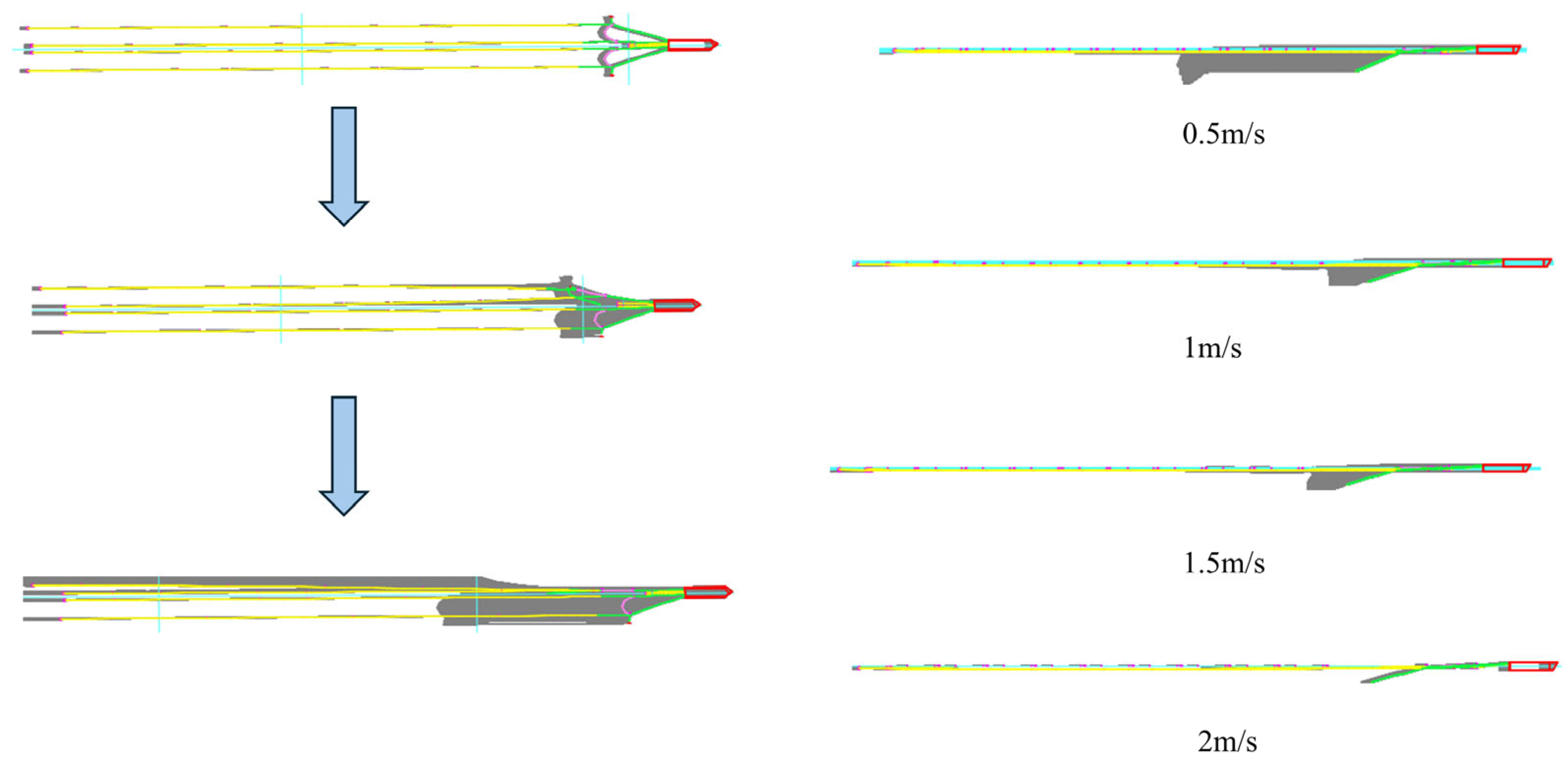
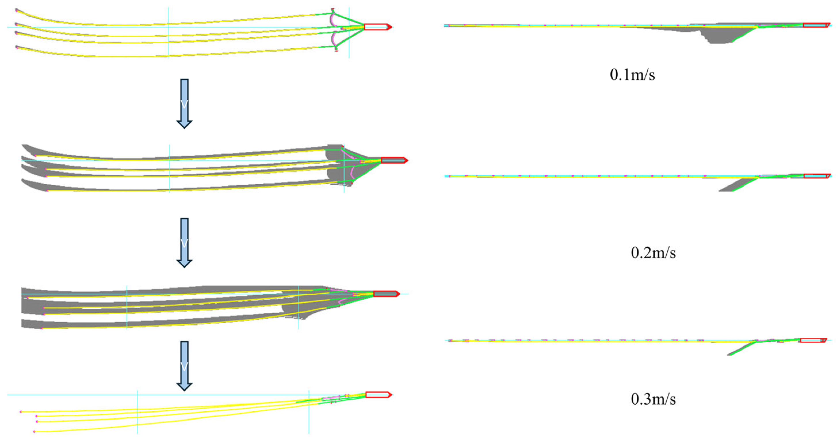
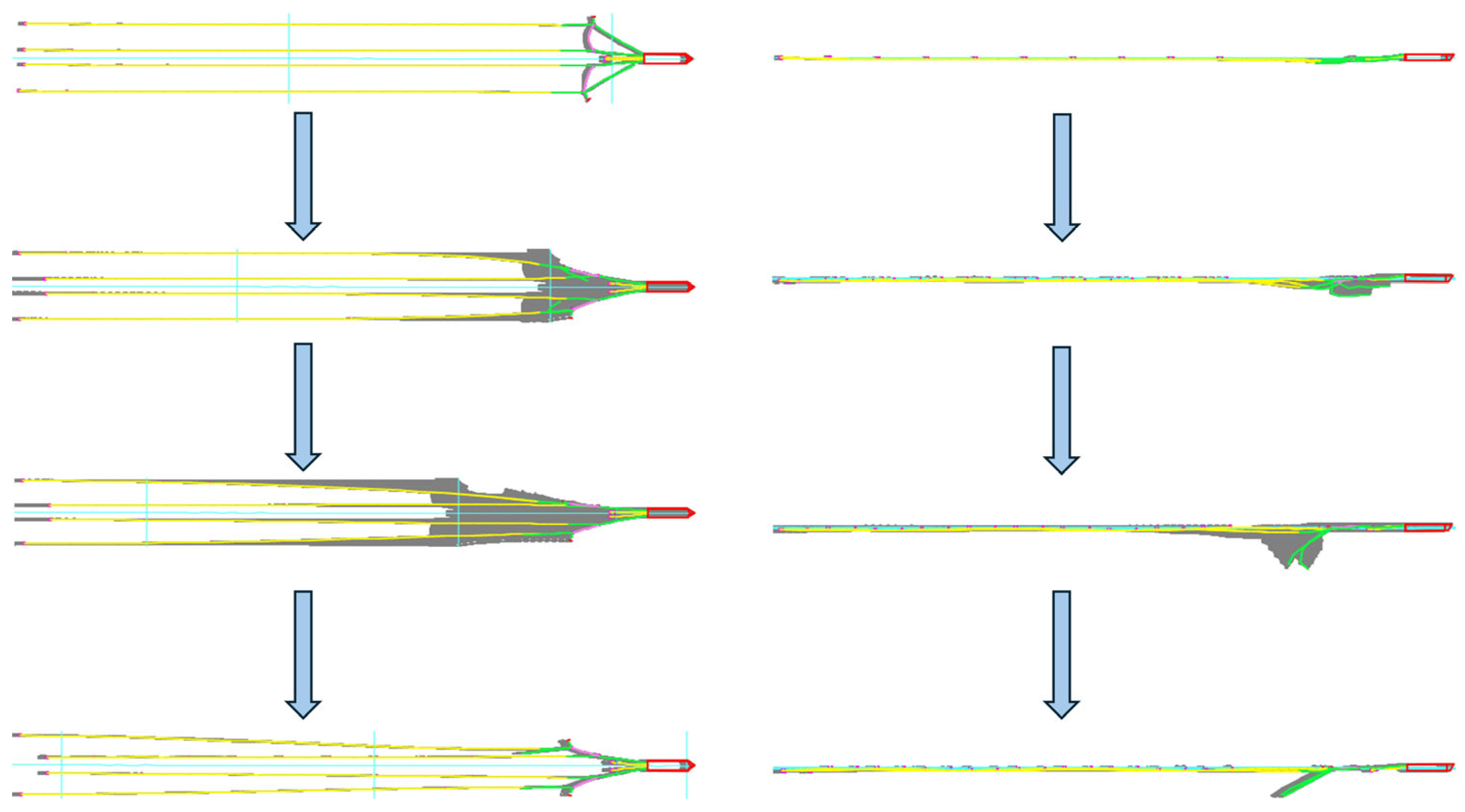
In this scenario, the breakage position of the mooring line is set at the root, and the reasons for the selection are as follows: (1) Under the condition that the forward direction of the tugboat is opposite to the ocean current, the axial tension of the main cable increases with the increase of the ocean current velocity, resulting in a further concentration of the force transfer load at the root position; (2) In Table 3 of the original text, the EI of the “Lead-in type mooring line” is 0.02 kN·m2, indicating a relatively low flexural stiffness. The root position, as a “rigid-flexible connection point”, is prone to stress concentration due to the sudden change in stiffness. Observation of Figure 3 shows that: the faster the countercurrent velocity is, the larger the angle of the broken port side cable A (i.e., the left-side guiding cable labeled A in the multi-branch towed array system, see Figure 2 for the system structure) deviates from the vertical downward direction after the system is stabilized; it can be expected that, if the countercurrent velocity continues to increase, the broken port side cable A will rotate around its still restrained end by a certain clockwise angle under the impact of the current (the angle is greater than 90°), but at this time, the towing end of the port side cable A is at the rear and its free end is submerged in the water below. However, at this time, the towing end of the port side guide cable A is at the rear and immersed in the water, and eventually the port side guide cable A is traveling steadily with its free end at the front and its towing end slanting downward, and the larger the current velocity is, the larger the angle of rotation around its own end is. Further observation reveals that the formation of the port-side towing cable undergoes a process in which the overall formation shifts to the port side first and then gradually returns to the center of the ship. The reason for this phenomenon is that the initial offset to the port side is due to the loss of the constraints of the port side guide cable A. When it continues to shift t to the left side to a certain extent, the port side towing cable A begins to be constrained by the limitations of the unfolding device A. Coupled with the current direction of the countercurrent at this time, the above factors lead to the port side towing cable A’s formation position will ultimately and gradually close to the middle of the boat direction.
Due to the breakage of the port side guide cable A, the towing system on the left side of the line array formation is significantly affected, when the system as a whole to achieve stability after the port side of the towing cable A formation position relative to the system intact when the overall movement to the right; the left side of the two towing cables between the formation of the spacing has become very small, and in the port side of the two guide cables near the tail end of the formation of the reunion of the two left side of the towing system and with the current velocity increases, the two left side towing cables overlap the formation interval is also becoming larger, so that mutual collision occurs; this phenomenon will make the two cables embedded in the actual project will be seriously damaged. With the increase of the current velocity, the two left side towing cables the overlapping position interval between the two left-side towing cables is also becoming larger, so that mutual collision occurs, this phenomenon in the actual project will make the two cables embedded in the sonar by serious damage, and due to the breakage of the outboard guide cable and the disorganization of the left side towing cable formation, the tension of the left side towing cable A is transferred to the left side of the spreader, resulting in the left side of the spreader also being subjected to a great deal of tension; in the process of the left side of the air gun umbilical cable will first be offset to the port side and then gradually returns toward the ship’s midline and the tension it bears is also significantly increased. For the right side of the line formation, the right side of the line formation was not much affected after the breakage of the port side guide cable, and the larger the current velocity, the better the right side of the line formation was maintained.
When the current direction is countercurrent, it can be inferred from the tension distribution of each towing cable at different current speeds that the greater the countercurrent velocity, the greater the tension on each towing cable, and due to the breakage of the port side guide cable, the dragging force on the two left-side cables is finally concentrated at the end of the middle guide cable B, which results in the tension on the middle guide cable B being much larger than that on the middle guide cable B1. The left spreader A is also subjected to a larger tension relative to the right spreader B.
In countercurrent and down current, the two cables on the right side of the towing system keep good formation, and there is no big formation change in the X and Y directions, while the two cables on the left side of the towing system change in the X and Y directions mainly due to the breakage of the guide cable on the left side of the port side of the cable; and in crosscurrents, due to the lateral impact of the sea currents, the towing system of the whole towing system, therefore, in the Y direction of the formation of the formation of the formation of the position of the larger changes will occur, and the closer to the tail end of the towing cable, the larger the offset in the Y direction, which is due to the closer to the tail end of the towing the stronger the flexure of the towing system caused by.

3.1.2. Dynamic Response of a Double Outboard Guide Cable During Failure Fracture Under Countercurrent Action

Due to the large number of towing cables in the system, if two guide cables break at the same time, the system is prone to mutual entanglement, making it difficult for the whole system to enter the static equilibrium stage quickly. Moreover, the longer the side cables, the worse the convergence of the system when they break at the same time, because with the increase of the length, the possibility of mutual entanglement of the two cables before reaching the static equilibrium stage and the duration of entanglement will be greatly increased. To facilitate the convergence of the system, the port and starboard cables are set to break at different stages. The starboard side cable is broken at the initial moment when the system enters the static equilibrium phase, and the port side cable is broken at the moment when the system enters the dynamic simulation phase. Later in this chapter, when it comes to the failure of both side cables, the starboard side cable breaks at the initial moment when the system enters the static equilibrium phase, and the port side cable breaks at the moment when the system enters the dynamic simulation phase.
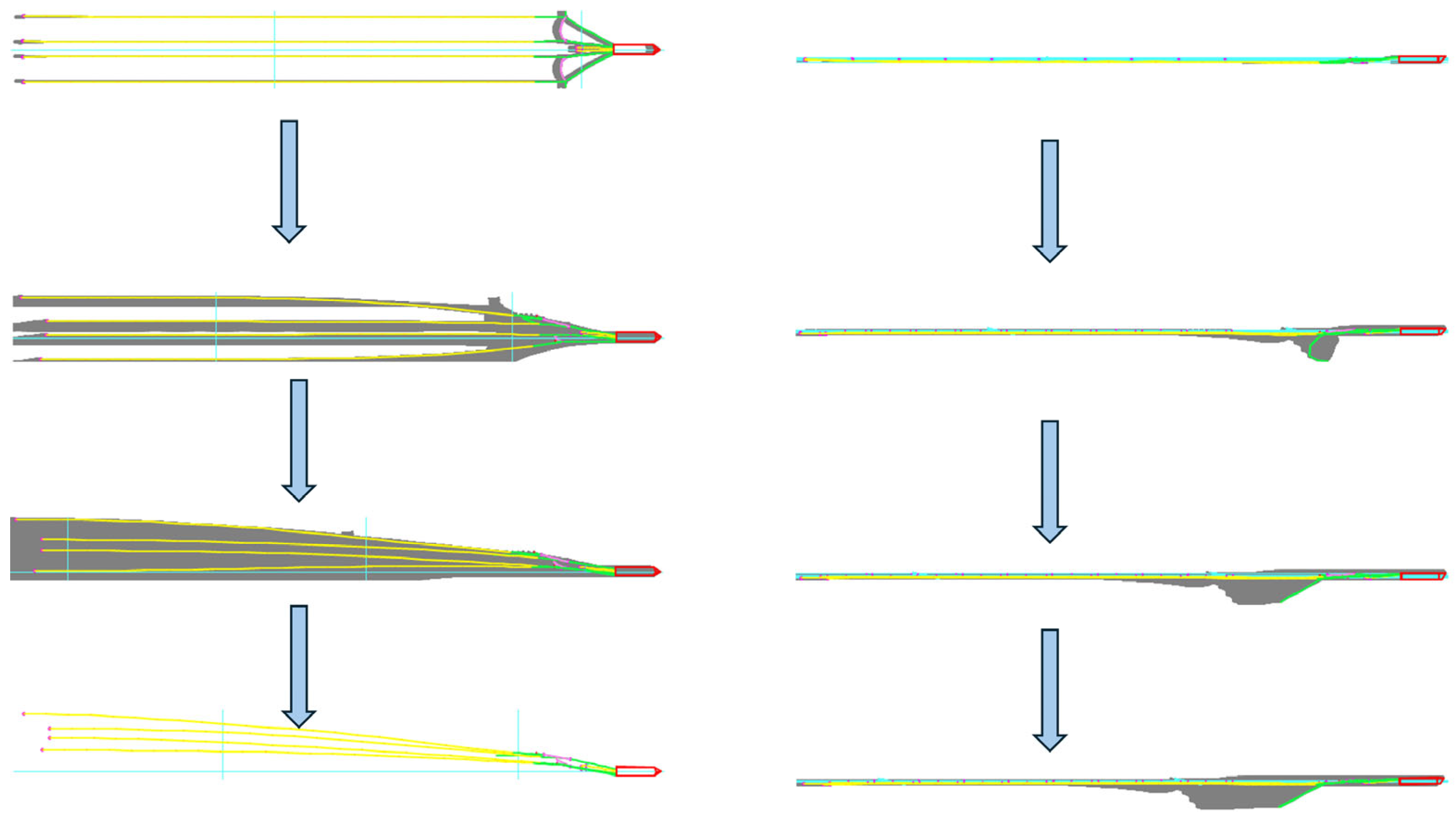
Observation of Figure 4 reveals that under countercurrent conditions, when both the port and starboard outboard guiding cables break, it is found that under different countercurrent velocities, when the whole multibranch towing system reaches stabilization, the towing cable formation in the whole towing system is symmetrical between left and right, and the larger the countercurrent velocities, the shorter the time needed for the towing system to reach the final stabilization stage is. There are some differences in the spatial pattern changes along the cable length at each time step before the whole towing system reaches stability, and the spatial pattern changes of the two guide cables are not synchronized at the initial stage, which is due to the difference in the moment of fracture; however, when the whole system enters into the stable stage, all the cables including the left and right side guide cables are symmetric at each time step, and the greater the countercurrent current, the shorter the time required for the towing system to reach the final stable stage. towing cables have the same cable body morphology at each time step.

3.1.3. Dynamic Response of the Port Side Guide Cable During Failure Fracture Under Downstream Action

In this case, the tugboat advances in the same direction as the current. As the towing cable is a flexible component, if the speed of the tugboat is less than the current speed in the downstream state, the towing cable will be compressed and curled by the impact of the current and it is difficult to achieve static equilibrium, resulting in the system failing to converge. Therefore, in the downstream state, the speed of the tugboat should be much larger than the speed of the current, so as to ensure that the force exerted by the sea current on the towing cable produces an axial tensile effect. After several simulation adjustments in the simulation, it is found that in this case, the speed of the tugboat should be at least 4–6 times of the current speed to ensure the convergence of the whole multi-branch towing system. That is to say, in this case, the greater t the difference between the tugboat speed and the current speed, the better the convergence of the system, the maximum speed of the current is about a quarter of the speed of the tugboat, when the current speed is very small, it is equivalent to the tugboat sailing in the still water.
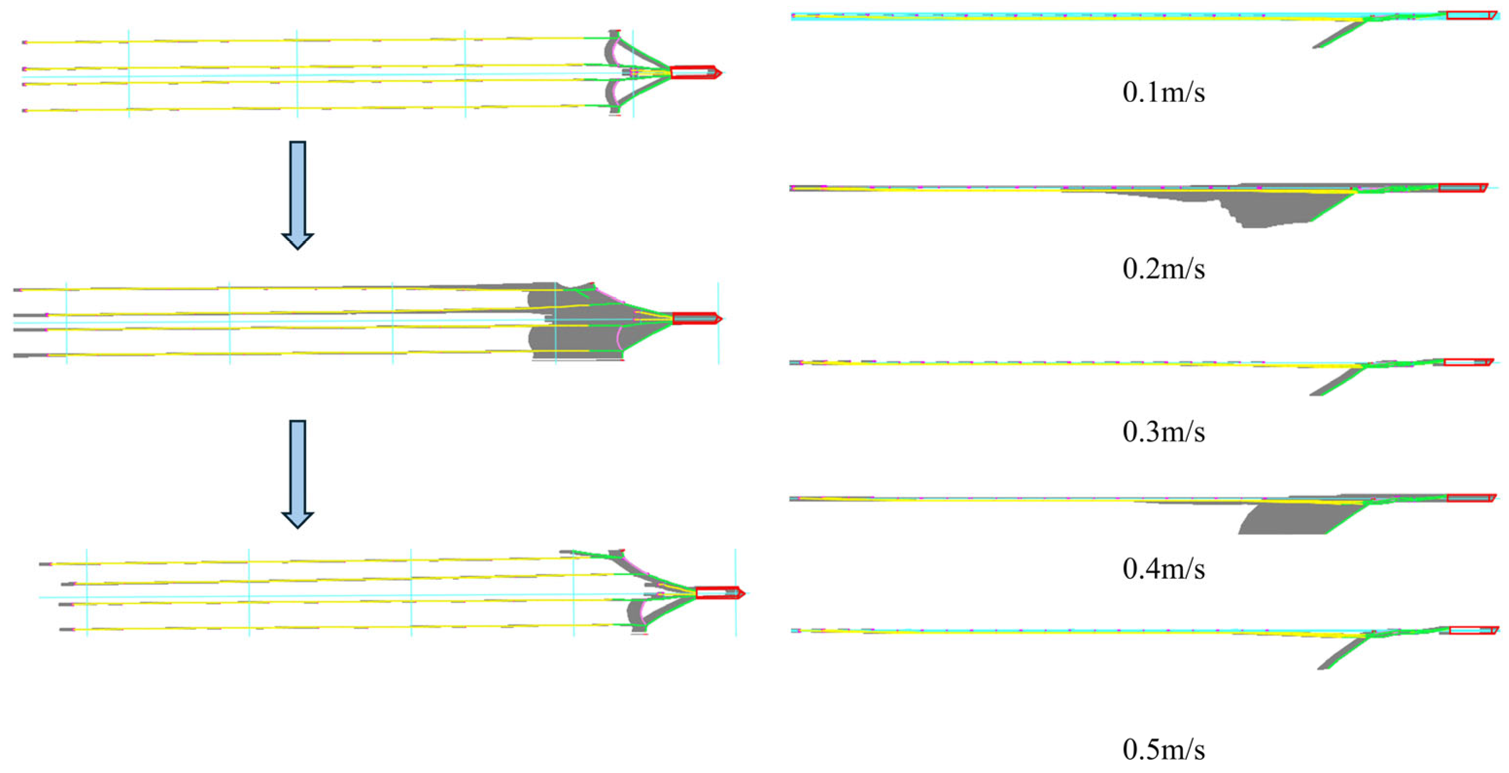
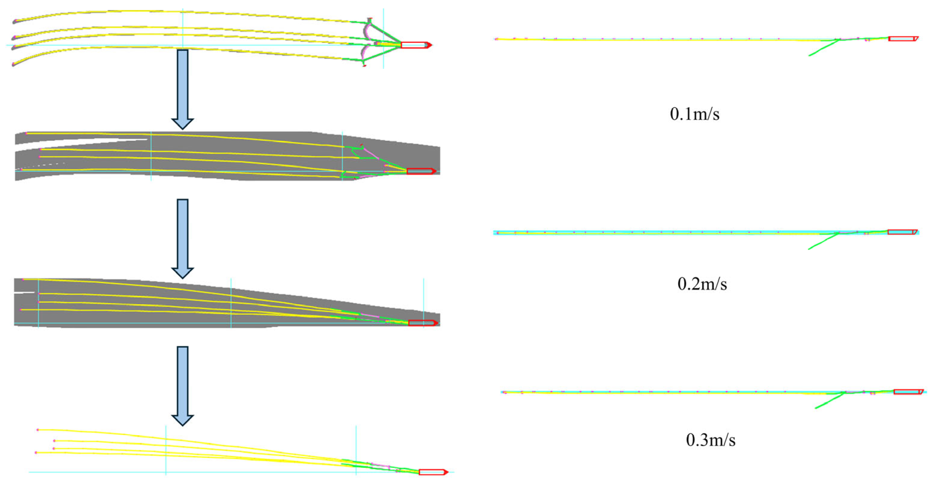
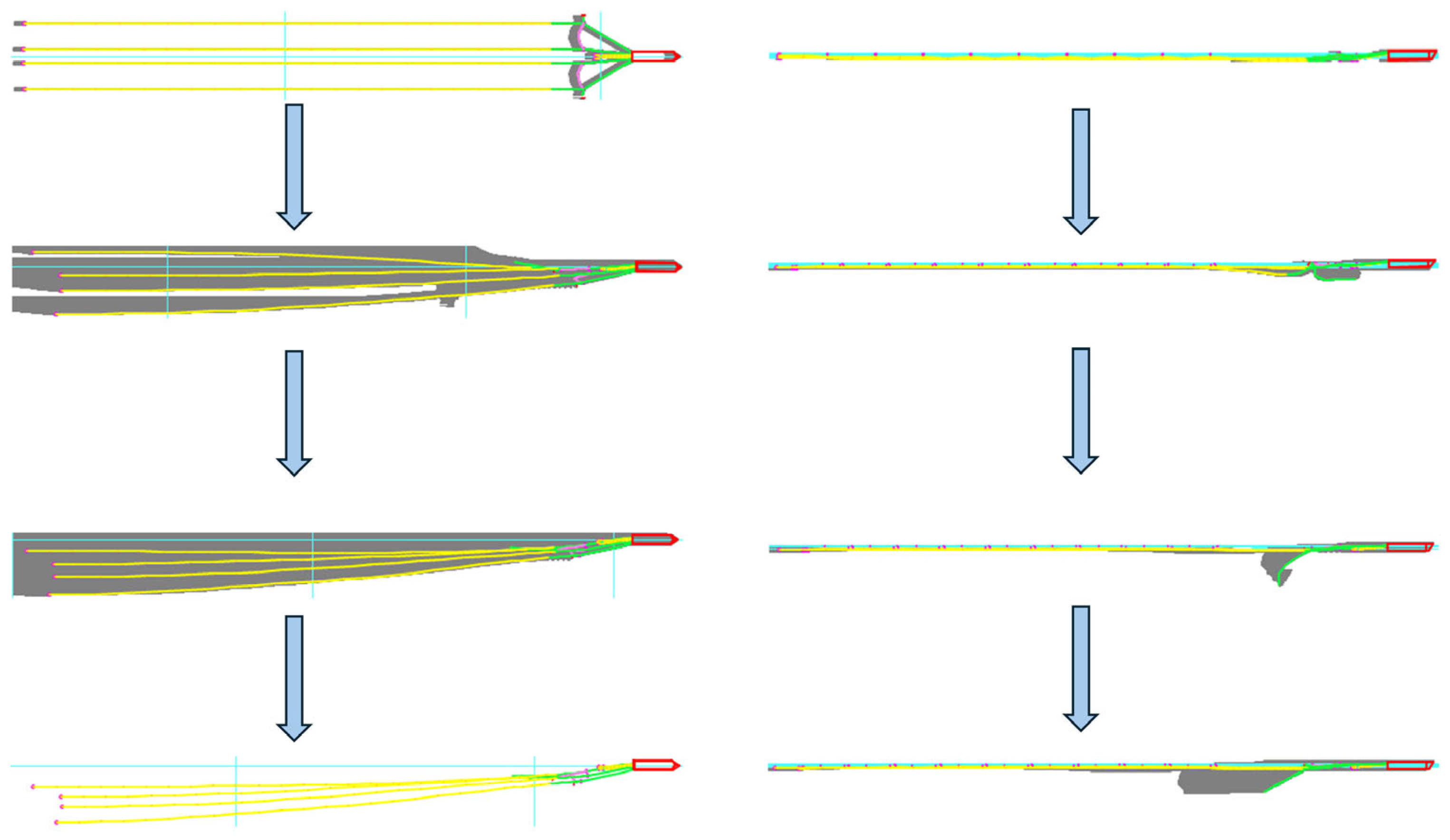
As Figure 5 shows that when the downstream current velocity is smaller than the towing speed of the tugboat, the larger the current velocity is, the smaller the angle of the broken port side cable deviates from the vertical downward direction after the system is stabilized, so it can be deduced that: if it can be realized in simulation, when the current velocity reaches the same speed as that of the towing speed of the tugboat, at this time, the broken port side cable should be in the natural hanging state. The larger the downstream current velocity, the smaller the angle of the broken port side cable deviating from the vertical downward direction after the system is stabilized; it can be expected that the larger the downstream current velocity is, the closer the broken port side cable is to the natural overhanging position (approaching but not reaching it), but at this time, the towing end of the port side cable is submerged into the water at the rear and bottom, and finally, the port side cable with its end at the front and the final towing end in the diagonally downward attitude is traveling steadily, and the larger the current speed is, the more it is in the natural overhanging state, and the greater the current velocity the smaller the angle at which it deviates from its natural overhanging position around its own end.
It was further observed that when the current velocity was 0.1 m/s, 0.3 m/s, 0.4 m/s, 0.5 m/s under the downstream condition, the overall formation of the port-side towing cable A did not undergo a significant offset back to the center of the ship after it was deployed after offsetting to the port side first, but when the downstream current velocity was 0.2 m/s, the phenomenon that the port-side line array was offset back to the center of the ship again. This is in marked contrast to the calculation results in the countercurrent condition. The spatial change of the overall formation of the port side towing cable A in the countercurrent condition will first be leftward and then return to the center of the ship, while there is no obvious phenomenon of returning to the center of the ship when the current velocity is low in the downstream condition. Combined with the results of countercurrent, it can be concluded that the reason for this phenomenon in the downstream state after the breakage of the port side of the guide cable A is: in the initial state to the port side of the offset is due to the loss of the constraints of the port side of the guide cable A, and when it continues to the left side of the offset to a certain extent, the port side of the towing cable A began to be restricted by the constraints of the unfolding of the spreader A, coupled with the direction of the current for the downstream tangential velocity is very small, so that the current of the Drag force is reduced, so the axial stretching effect on the towing cable is weakened, because the length of the towing cable is limited, so the weakening of the axial stretching effect in the transverse direction of the role of the expansion can be extended to increase the length of the above factors lead to a variety of comprehensive factors lead to the port side of the towing cable A formation position in the deviation of the port side of a certain distance directly to the dynamic equilibrium, so in the downstream state there is no general to the direction of the ship in the direction of the again However, when the downstream velocity is 0.2 m/s, the discharge frequency of the velocity synthesized by the velocity and the towing speed of the tugboat is similar to the self-oscillation frequency of the spreader A, which will trigger the high-frequency vibration of the spreader A, and the perturbation brought about by this vibration will break the equilibrium of the left line array system, and eventually make the formation of the port side towing cable A offset to the ship’s mid-direction once again. That is to say, in the downstream state, between the minimum allowable operating current speed and the maximum allowable operating current speed, it is possible to have a current speed that will make the towing line array formation spacing greatly reduced, and its specific size is related to the tugboat’s towing speed and the self-oscillating frequency of the spreader on the towing line array. It is possible to change its own vibration period by adding some attachments or reinforcing materials to the spreader, which can ensure a better formation spacing of the multi-branch towed array system in all the allowable current speed ranges during downstream operation in some sea areas. Therefore, it is not the case that the lower the current speed, the better the overall formation of the system will be maintained in the downstream condition.
In the downstream current, except for individual current, except for the current velocity of the larger, multi-branch towed array system formation stabilization after the horizontal spacing between the towing cable in the system to achieve stability can be maintained relatively stable; and in the countercurrent current, with the current velocity increases, multi-branch towed array system formation stabilization after the horizontal spacing between the towing cable the smaller. The horizontal spacing between the towing cables after stabilization of the multi-branch towed array system in the downstream condition is larger than that in the countercurrent condition.
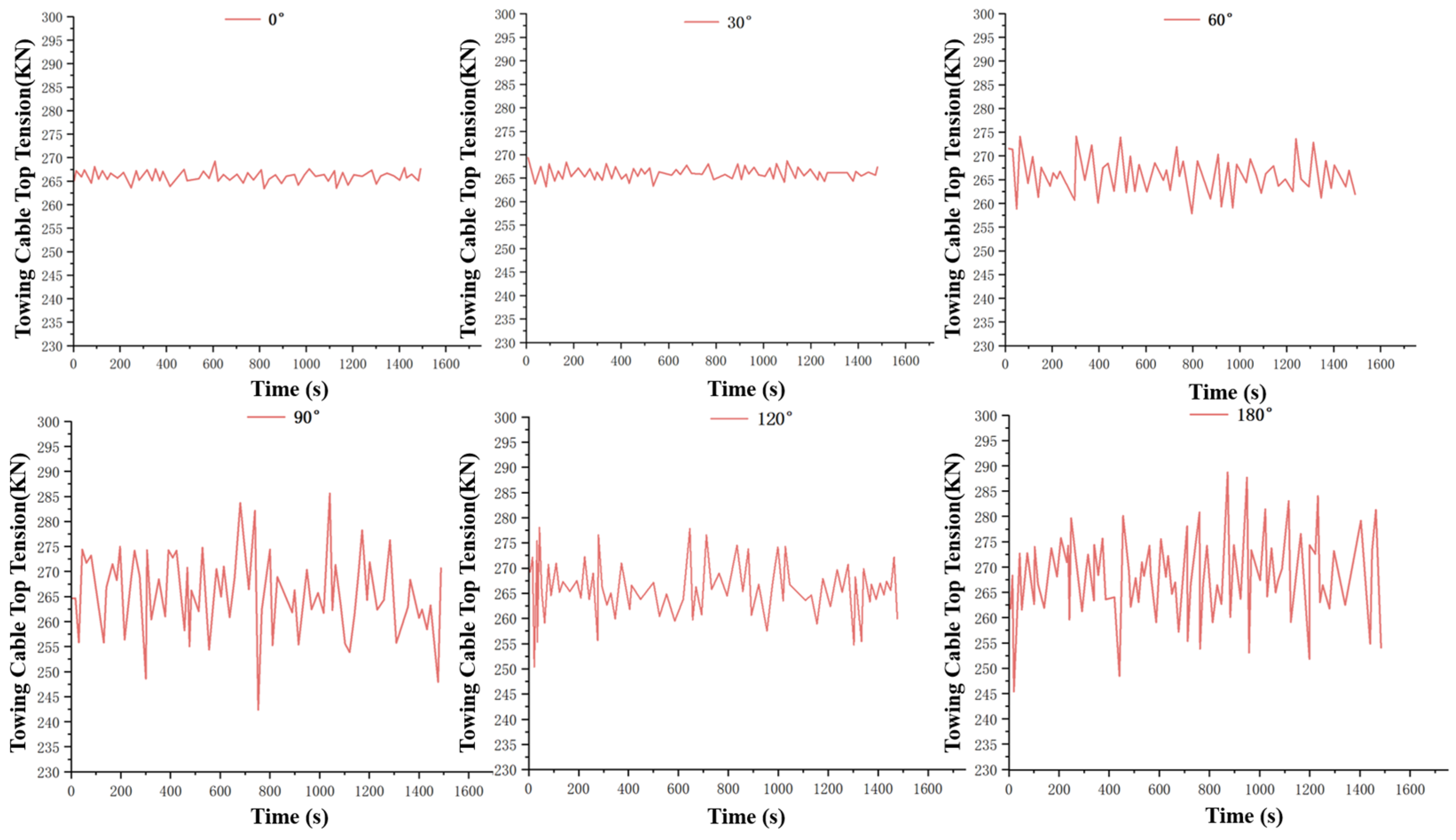
It can easily be concluded that when the downstream current speed is less than the towing speed of the tugboat, the higher the current speed, the lower the tension in each towing cable. This is due to the fact that the combined velocity of the tugboat speed and the current decreases as the current speed increases resulting in a decrease in the velocity of the towing cable relative to the current, which leads to a decrease in the towing force on the towing cable.
It is further found in the simulation that when the direction of current is the same as the direction of motion of the tugboat, the closer the current velocity is to the motion velocity of the tugboat, the more difficult it is for the system to converge. This is because when the current velocity happens to be isotropic with the tugboat velocity, theoretically it is equivalent to the tugboat traveling in the same direction with the sea current at the same speed as the sea current; however, due to the delayed motion transfer, the motion of the tugboat will not be immediately transferred to the back half of the towing cable system, so the motion of the back half of the towing cable in the system will be firstly affected by the action of the incoming current, and the direction of the incoming current will cause the back half of the towing cable to move to the right; and since the towing cable is a typical flexible component, under the delay of the ship’s motion transfer, the towing cable will be compressed in the axial direction, and the shape of the towing cable becomes difficult to adjust, resulting in the nodes of the towing system are difficult to achieve static equilibrium on the spatial force, which will make the simulation into the dynamic phase of the failure, and the system will eventually diverge. This phenomenon shows that, in practical engineering, when the tugboat and the current are in the same direction, and the speed and the current velocity is the same, it is very unsuitable for towing operations, in this state of the entire towing system in the towing cable cannot be unfolded, and it is likely to be washed by the current to the end of the tugboat. If this kind of sea state engineering operation is unavoidable, it is advisable to increase the towing speed of the tugboat, make the towing speed of the tugboat is large enough to ensure that in a very short period of time can be the tugboat’s movement to the back half of the towing system, ensures that all segments and nodes of the towing cables achieve static equilibrium, so as to ensure that the entire towing process can proceed dynamically and the stability of the dynamic simulation.

3.1.4. Dynamic Response of a Double Outboard Guide Cable During Failure Fracture Under Downstream Action

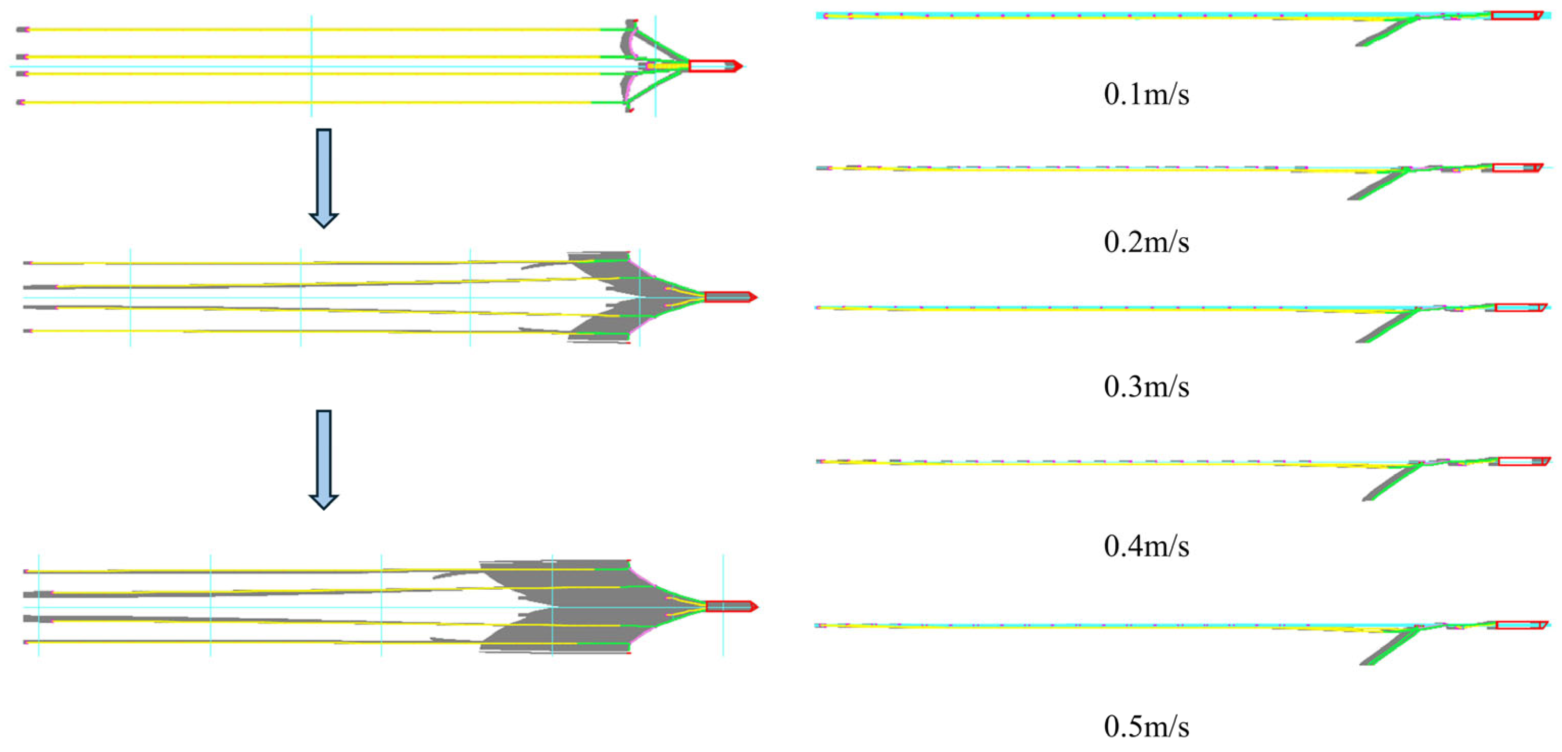
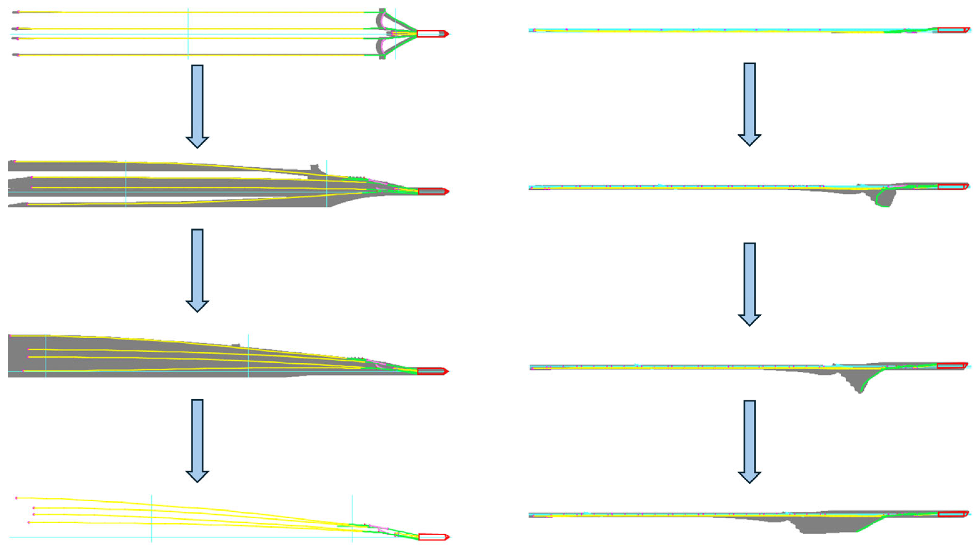
As Figure 6 shows the change of the multiline array after the breakage of the double outboard guide cables in the downstream state. As a matter of fact, the author found from years of simulation experience that in the countercurrent state, the speed of the tugboat can be extremely small or 5–20 times of the current speed, at which time the whole system is still relatively easy to reach the convergence state; however, in the downstream state, it is divided into two kinds of cases: one is that the towing speed of the tugboat is smaller than the current speed, and as the towing speed of the tugboat is closer to the current speed, the whole system’s convergence becomes worse and worse, and when the tugboat’s towing speed is not much different from the current speed, the whole towing system will not be able to converge; in the downstream state, when the speed of the tugboat is greater than the speed of the current, when the tugboat speed is 2–6 times of the current speed, the system can still converge, but the tension of each towing cable will be larger in this case. This tells us that in actual engineering practice, if we want to carry out towing operations in the downstream state, there are two methods to choose from, one is to travel at a towing speed that is much lower than the current speed, which has the advantage that the towing cables are under less tension but requires more time; the other is to make the tugboat travel at a high speed with a current speed that is 2–6 times of the current speed, but this has the advantage that it requires less time but the towing cables are under Tension is greater, easy to fatigue and fracture.

3.1.5. Dynamic Response to Failure Breakage of Port Side Guide Cable Under Cross Current (90°, 270°)

For the single-branch towing system, since there is only one towing cable in the whole system, within the safety limit, the allowable change of its formation pattern is still relatively large, so the change of the current direction in the single-branch towing system can be very large [75,76,77,78]. However, for the multibranch system, since there are multiple towing cables in the whole system, the change of the current direction, especially under the effect of the cross-current, the change of the formation pattern of each individual towing cable will be significantly changed. However, for a multi-branch towing system, because there are multiple towing cables in the system, changes in the direction of the sea current, especially under the effect of cross current, the formation position of individual towing cables will change significantly, and because the towing cables themselves are long flexural components, this change is nonlinear, and this change in the formation position of individual towing cables will lead to nonlinear changes in the distance between individual towing cables, and this change in the towing cables at different positions is random [79]. For a multi-branch towed system, if it is to be able to maintain a certain formation position in a certain cross-current sea state, it is necessary to maintain a certain formation position under normal operation. of a multibranch towing system, it is necessary to limit the magnitude of the cross-current speed.
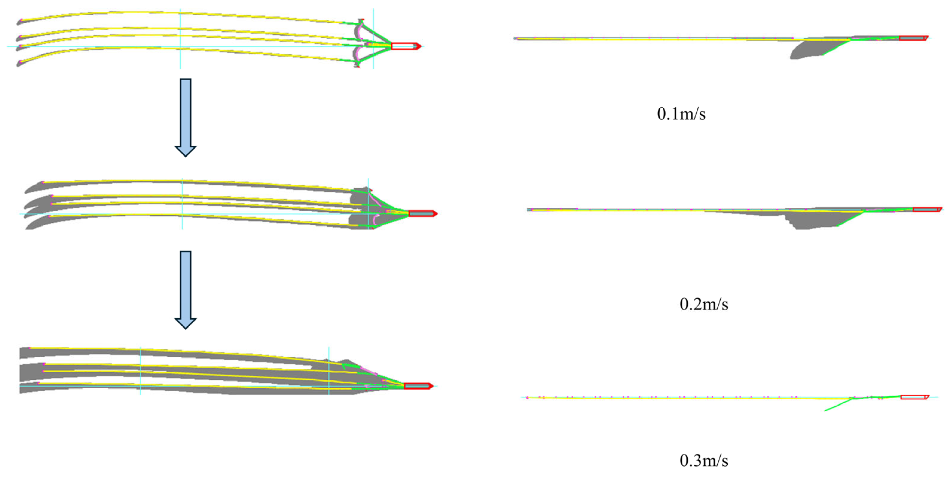
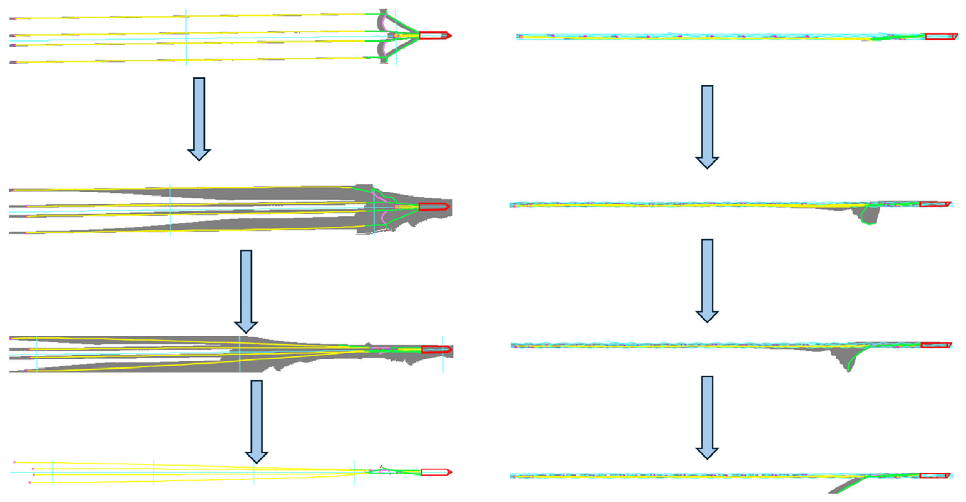
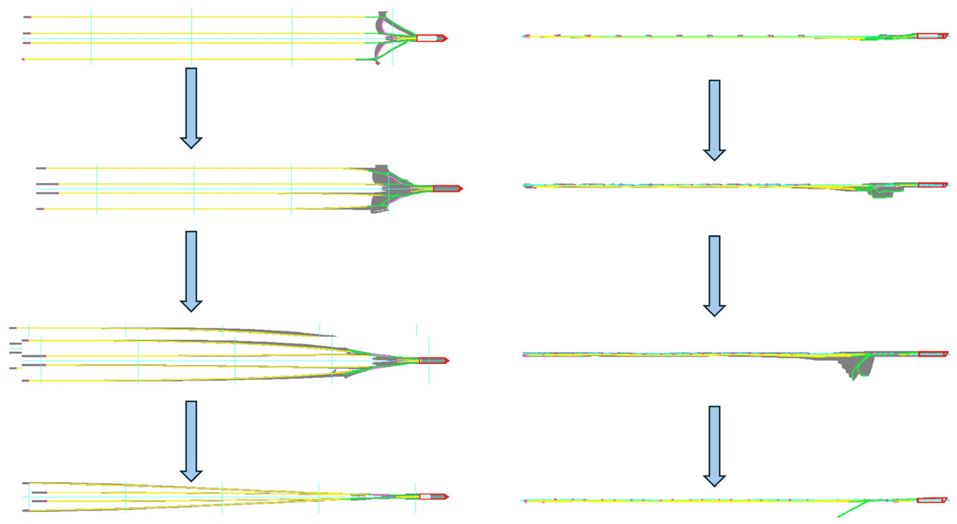
Observation of Figure 7 and Figure 8 reveals that, in the transverse current state, the flexure of the towing cable is fully manifested in the initial stationary stage of the multibranch system, and the transverse current direction leads to a small transverse oscillation of the towing cable’s trailing end, which is opposite to the direction of the wave direction extension, and with the increase of the transverse current speed, the amplitude of the small transverse oscillation of the towing cable’s trailing end will also increase. However, once the tugboat starts to move, the lateral stretching of the towing cable by the tugboat has a very obvious inhibiting effect on the transverse oscillation of each towing cable end. When the speed of the tugboat is stabilized, the transverse oscillations of the trailing end of the towing cable can be almost completely suppressed. This tells us that, for the transverse oscillation of the trailing end of the towing cable caused by cross-current, it can be suppressed by increasing the speed of the tugboat when the cross-current velocity is small, but the speed of the tugboat at this time should be limited to a certain range for safety reasons. That is to say, cross-current state of the tugboat towing speed can increase the magnitude is also very limited.
Compared to the size of the maximum current velocity at which the multibranch towing system can reach convergence under countercurrent and upstream current, the maximum current velocity at which the multibranch towing system reaches convergence under crosscurrent condition is much smaller. It is found in the simulations that for the towed line array in this chapter, the system has difficulty in reaching convergence when the cross current velocity exceeds 0.3 m/s. In a way, the difficulty of convergence in the simulation when the cross- current velocity is too large means that in practice it is difficult for the system to achieve the dynamic equilibrium and stability required for its in-situ operation. In practical engineering this means that it will be difficult for individual towing cables in a multi-branched line array to achieve a relatively stable formation when the cross-current current velocity exceeds a certain limit under cross-current conditions.
And with the increase of cross-current current velocity, when the current velocity reaches 0.3 m/s, the whole multi-branch towing line system presents a completely different formation from that when the current velocity is 0.1 m/s and 0.2 m/s: when the port side guide cable breaks, when the cross-current current direction is 90°, the towing cables of the right half of the whole multi-branch towing line array have not been offset over the mid-station surface when the current velocity is 0.1 m/s and 0.2 m/s, and the starboard guide cable A1 is still functioning, but there is still a towing cable on the right and left sides of the tugboat. The starboard guide cable A1 is still functioning, and although the whole multi-branch towed array system is no longer symmetrical, the left and right sides of the tugboat still have the existence of the towing cable, and the formation is still maintained to a certain extent; while in the current velocity of 0.3 m/s, the starboard guide cable A1 does not break, but the band is no longer enough to maintain the right side of the guide cable, and all the towing cables in the right side of the multi-branch towing cable array system have already crossed the mid-station surface. The entire multi-branch towed array system on the right side of the towing cable has crossed the center station surface, and drastically shifted to the left. When the port side guide cable A breaks, the transverse current flow direction is 270°, due to the existence of the starboard side guide cable, when the transverse current flow velocity is small, the formation of the two towing cables in the right half of the multibranch towed array system can maintain a better shape, but the formation of the two towing cables in the left half of the left half of the system loses the port side guide cable A to maintain the formation of the two towing cables, it will be rapidly shifted to the right, and in the current velocity of 0.2 m/s, it has been all shifted across the center station surface, which indicates that when the transverse current flow velocity is 0.2 m/s, all of the towing cables in the right side of the system have already crossed the center station surface. This indicates that when the direction of the incoming cross current is on the same side as that of the broken port side guide cable, it will further reduce the ability of the line array to resist the cross current, while if the direction of the incoming cross current is not on the same side as that of the broken port side guide cable, the overall ability of the line array to resist the cross current will be slightly improved compared with the situation when the line array is on the same side, and with the increase of cross-current current velocity, when the current velocity reaches 0.3 m/s, the whole multi-branch towing line system presents a completely different formation from that when the current velocity is 0.1 m/s and 0.2 m/s: when the port side guide cable A breaks, when the cross-current current direction is 90°, the towing cables of the right half of the whole multi-branch towing line array have not been offset over the mid-station surface when the current velocity is 0.1 m/s and 0.2 m/s, and the starboard guide cable A1 is still functioning, but there is still a towing cable on the right and left sides of the tugboat. The starboard guide cable A1 is still functioning, and although the whole multi-branch towed array system is no longer symmetrical, the left and right sides of the tugboat still have the existence of the towing cable, and the formation is still maintained to a certain extent; while in the current velocity of 0.3 m/s, the starboard guide cable A1 does not break, but the band is no longer enough to maintain the right side of the guide cable, and all the towing cables in the right side of the multi-branch towed array system have already crossed the mid-station surface. The entire multi-branch towed array system on the right side of the towing cable has crossed the center station surface, and drastically shifted to the left. When the port side guide cable A breaks, the transverse current flow direction is 270°, due to the existence of the starboard side guide cable, when the transverse current flow velocity is small, the formation of the two towing cables in the right half of the multibranch towed array system can maintain a better shape, but the formation of the two towing cables in the left half of the left half of the system loses the port side guide cable A to maintain the formation of the two towing cables, it will be rapidly shifted to the right, and in the current velocity of 0.2 m/s, it has been all shifted across the center station surface, which indicates that when the transverse current flow velocity is 0.2 m/s, all of the towing cables in the right side of the system have already crossed the center station surface. This indicates that when the direction of the incoming cross current is on the same side as that of the broken port side guide cable, it will further reduce the ability of the line array to resist the cross current, while if the direction of the incoming cross current is not on the same side as that of the broken port side guide cable, the overall ability of the line array to resist the cross current will be slightly improved compared with the situation when the line array is on the same side.
Further comparative observation of two cross-current current direction under the state of the port side of the guide cable A breakage of the multi-branch towed formation changes can be found: when the cross-current current direction of 90°, the current velocity of 0.3 m/s, although the breakage of the port side of the guide cable A so that the left half of the two towing cables lost the constraints on the formation, but due to the right half of the multi-branch towline formation in this case the two cables are on the current, which is the impact of the two cables is greater than that of the left half of the two cables, so the right half of these two cables although the starboard guide cable A1 constraints, but still appeared in the overall bias toward the left half of the two towing cable. The impact of the two cables is greater than that of the two towing cables in the left half, so although the two cables in the right half have the restriction of the starboard side guide cable A1, there is still a phenomenon that the two cables in the right half are biased to the left side and at the same time are close to each other, and the two cables in the left half, due to the hindering effect of the two cables in front of them on the currents, receive the force of the transverse current, although the force of the currents has increased in relation to low-current speeds, but the increase in this increase Instead, this increase compensates for the lack of restriction caused by the breakage of the outboard guide cables, and thus the formation is relatively good. In other words, the sheltering effect of the onshore cable has a positive effect on maintaining the formation of the backwater cable when the cross-current velocity is high.

3.1.6. Dynamical Response of a Double Outboard Guide Cable During Failure Fracture Under Cross-Currents

Observation of the morphology changes of the multibranch towing system in the 90° and 270° cross-currents states in Figure 9 and Figure 10 reveals that: the morphology of the line array after the multibranch line array reaches stabilization after the breakage of the double outboard guide cables is only related to the direction of the currents and the final stabilized line array morphology under the same cross-currents current speeds in the 90° and 270° cross-currents current directions is symmetrical to each other; further observation reveals that It is further observed that the line formation is not symmetrical in the two cross-current current directions before the line formation is stabilized, and this asymmetry is due to the non-synchronization between the moment of the action of the sea current under the two cross-currents and the moment of the breakage of the outboard guide cable. In both cross current directions, the starboard side guide cable breaks first, and then the port side guide cable breaks, but the changes of the line array before reaching stability are different in the two cases: when the direction of the cross current is 90°, the current acts on the right side of the line array in the simulation stage, and the port side guide cable does not break at the initial stage and still plays a role in maintaining the stability of the left side of the line array, whereas the starboard side guide cable has already broken, and therefore the line array has already been stabilized at the initial moment of the simulation, and the starboard side guide cable has already broken. At the beginning of the simulation has lost the role of the right side of the array to maintain the formation; and when the transverse current direction of 270°, the current in the simulation phase first acted on the left side of the line array, in the initial stage of the port side of the guide cable did not break also play a role in maintaining the stability of the left side of the array, so in the initial stage of the port side of the array can be maintained, and due to the current arrives at the moment of the starboard side And due to the moment of the current arriving at the starboard side and arriving at the port side, there is a certain time difference, so although the starboard side guide cable has been broken at the initial moment, but the formation of the right side of the array in the initial short period of time will still be maintained and stabilized, and with the increase of time, the action of the sea current extends to the starboard side, and the stable form of the starboard side of the array is then broken; which is exactly the cause of the two kinds of transverse currents under the action of the sea current at the moment of the moment and the moment of the breakage of the port side cable of the non-synchronous main reason. This is the main reason for the non-synchronization between the moment of current action and the moment of breakage of the outboard guide cable under the two cross currents. Therefore, the difference in the direction of the cross currents in the case of the breakage of both outboard cables affects the change of the line array when it has not yet reached the stabilization stage. Moreover, since the breakage moments of the port and starboard cables are different in this example, if the port and starboard cables break at the same time, the change of the line formation should be symmetrical for the two transverse current flow directions.
To summarize, the construction operation of multi-branch towing system under cross-current sea state has certain requirements on the size of cross-current current speed and the size of tugboat towing speed, which can be carried out within a certain range, but beyond a certain current speed, the formation of multi-branch towing line in cross-current state will inevitably appear in the formation disorder. Therefore, if due to certain practical needs or military needs, need to detect towing in the cross-current current velocity of the sea, in the increase of the spacing between the different towing cable at the same time, but also in the towing cable on the outside of the main nodes of the force to increase the bending strength of some of the larger strength of the support material, if possible, along the length of the towing system towing cable can be set up in sections along the length of the lightweight formation limiting frame, so that you can Greatly improve the ability of multi-branch towing system to operate in cross-current sea state. In the large cross current, it is not recommended to increase the towing speed of the tugboat to overcome the effect of cross current on the lateral swing of the towing cable and the lateral offset of the formation, because at this time the role of this method is quite limited, and in the large cross current if the tugboat is moving at high speeds, it is very likely to be capsized.

3.2. Dynamic Response to Wave Action

In engineering terms, for the consideration of safety assurance and accuracy of measurement data, since towing operations are generally not carried out in waters with large wave heights and short wave periods, it is only meaningful to carry out detection towing in microwave and longer wave period waters [80,81,82,83]. Therefore, the wave height in this case is set to 0.5 m, the wave period is 6 s, and the wave theory is linear wave.

3.2.1. Dynamic Response of the Port Side Guide Cable During Failure Breakage Under Counter Wave Action

In the case where the wave direction is opposite to the advancing direction of the tugboat, the fracture location is still at the root, but the cause newly adds the “impact superposition effect” of wave loads: (1) Based on the wave absorption equation in Section 2.2, when sailing against the waves, the root position needs to bear both the axial dynamic tension of the main cable and the vertical impact force of the waves simultaneously. The equivalent stress fluctuation range expands to 130–170 MPa, approaching the yield strength. (2) As mentioned in Section 3.2.1 of the original text, “the number of bent components of the towing cable increases when sailing against the waves.” The root position, as the connection point between the mooring cable and the expander, has its bending deformation restricted by the expander and cannot release stress through deformation. Eventually, it becomes the starting point of fracture. Observation of Figure 11 shows that the morphology of the multi-branch towed system changes in the counter-wave, and it is found that, unlike under the action of the current, under the action of the wave, it is obvious that under the wave, under the wave beat, the multi-branch towing line array produces wave vibration, and compared with the action of a single current, the vibration of the towing cable in the vertical direction in the towing system has become very obvious. This wave vibration is specifically reflected in the towing system of each node of the towing cable with the ups and downs of the waves and low amplitude, cyclic sustained cyclic vibration, this sustained cyclic vibration is very likely to cause resonance inside the towing cable inlaid sonar and thus reduce the accuracy of the measurements, but also prone to lead to fatigue damage, and in this case, the flexure of the towing cable is more fully embodied, compared with the towing system under the action of a single stream, the towing system under the action of the counter-wave multi-branch towing system in the towing cable irregular bending and torsion of the parts increased significantly, especially in the port side of the guide cable A breaks to the whole system to reach the stability of the phase before the towing system of the nonlinear vibration and torsion of the towing system increased significantly; and in the system to reach the stability of the whole system, the towing After the stabilization of the whole system, the individual towing cables in the system will continue to vibrate with low amplitude and periodicity in response to the cyclic fluctuations of the waves Observation of Figure 11 shows that the morphology of the multi-branch towing system changes in the counter-wave, and it is found that, unlike under the action of the current, under the action of the wave, it is obvious that under the wave, under the wave beat, the multi-branch towing line array produces wave vibration, and compared with the action of a single current, the vibration of the towing cable in the vertical direction in the towing system has become very obvious. This wave vibration is specifically reflected in the towing system of each node of the towing cable with the ups and downs of the waves and low amplitude, cyclic sustained cyclic vibration, this sustained cyclic vibration is very likely to cause resonance inside the towing cable inlaid sonar and thus reduce the accuracy of the measurements, but also prone to lead to fatigue damage, and in this case, the flexure of the towing cable is more fully embodied, compared with the towing system under the action of a single stream, the towing system under the action of the counter-wave multi-branch towing system in the towing cable irregular bending and torsion of the parts increased significantly, especially in the port side of the guide cable A breaks to the whole system to reach the stability of the phase before the towing system of the nonlinear vibration and torsion of the towing system increased significantly; and in the system to reach the stability of the whole system, the towing After the stabilization of the whole system, the individual towing cables in the system will continue to vibrate with low amplitude and periodicity in response to the cyclic fluctuations of the waves.

3.2.2. Dynamic Response of a Double Outboard Guide Cable During Failure Breakage Under Counter-Wave Action

After further observation of Figure 12, it is found that, in the counter-wave direction, no matter the single outboard guide cable fails to work at sea and the double outboard guide cable fails to work at sea, when the towing system reaches the stabilization, the towing formation of the multibranch towing system is worse (the spacing between cables close to the end of the tail end of the towing cable is larger, and the spacing between cables nearer to the towing end of the towing cable is smaller), and the different spacings of each cable along the length of the towing cable are not equal, and the spacing distribution is more discrete and not regular. The spacing distribution is relatively discrete and irregular, and the left and right formation distribution of the whole multi-branch towing system is similar to two acute triangles with very small top angles, which is not conducive to the unfolding of offshore construction operations.
In fact, when the wave height gradually increases to a certain amplitude and the wave frequency increases to a certain amplitude under the counter-wave condition, it will cause the tugboat to undergo a certain amplitude of sustained transverse rocking, and this transverse rocking motion of the tugboat has an unnoticeable effect on the spatial shape of the formation of the multibranch towed array system, in addition to the unpredictable effect on the transverse spacing between each towing cable in the formation, the sustained and violent transverse rocking will In addition to the unpredictable effect on the lateral spacing between the towing cable in the formation, a sustained and violent cross-swing will make it easier for the towing cables to become intertwined. Due to space limitation, the effect of wave height and wave frequency changes on the formation of multi-branch towing lines in counter-waves is not further analyzed here, but in fact it is very instructive for towing operations in counter-waves in waters with a wide range of wave frequency and wave height changes. If the towing operation is to be carried out in such an area under some specific requirements, the relatively safe operating intervals (safe interval of wave height and wave frequency) can be obtained through this analysis, and interested readers can carry out a more in-depth and detailed study on this issue.

3.2.3. Dynamic Response of an Outboard Guide Cable During Failure Breakage Under Downwash Action

Under the premise that the wave height and period are the same and the wave speed is less than the speed of the tugboat (the wave height is set to be 0.5 m, the wave period is 6 s, and the wave theory is the linear wave theory), it is found after observing Figure 13 that the vibration of the towing cable in the towing system is more intense in the down wave than in the up wave, which is due to the fact that the wave speed and the tugboat’s forward direction are the same in the up wave but the wave speed of the wave is the opposite of the tugboat’s forward direction in the up wave. The wave speed is the same as the direction of the tug’s progress in good waves, but the wave speed is the opposite of the tug’s progress in bad waves. Tugboat in still water with a certain speed straight, the towing cable is in the state of being stretched, in the smooth waves caused by the towing force will increase the towing cable along the degree of axial stretching, which helps to reduce the violent degree of vibration of the towing cable; but when the counter-wave, due to the magnitude of the speed of the wave is smaller than the size of the tugboat’s speed, this time, although the towing force caused by the wave cannot make the towing cable is compressed in the axial direction, but it will be weakened towing cable is axial stretching degree, towing cable axial stretching The weakening of the axial stretching of the towing cable results in the towing cable being more susceptible to violent vibration.
Comparative observation can be found, whether it is with the wave or against the wave, in the double outboard guide cable failure and breakage, when the whole multi-branch towing system is stabilized, the morphology change of the port side cable and the starboard side cable A1 will have a very small amplitude of asynchrony, this kind of asynchrony is due to the release of the two outboard cables at different moments resulting in the encounter with the wave is different at different moments caused by the waves are also cyclical fluctuations, this will Because the waves are also cyclic, this results in a small phase delay in the spatial morphology and vibration of the two outboard cables, which will always exist due to the cyclicity of the waves. However, under the action of the current, no matter whether it is downstream or countercurrent, because the current velocity is constant, when the whole multi-branch towing system is stabilized, after the failure and breakage of the two outboard cables, the morphology change of the port side cable and the starboard side cable A1 will be synchronized and stabilized to maintain in a certain shape, and after stabilization, no periodic vibration will occur in general (in a particular current velocity is possible to occur vortex vibration).
Compared to the formation of a multi-branch towed array system with a counter-wave, the stabilized formation is much better with the wave than with the counter-wave. With the exception of a small section very close to the towing end of each towing cable, the towing cable in the entire towing system are well parallelized over a fairly long length, and the spacing between the towlines is approximately the same, which is conducive to the development of maritime towing reconnaissance.

3.2.4. Dynamic Response of the Port Side Guide Cable in Case of Failure Breakage Under Cross-Wave Action (90°, 270°)

Observing Figure 14 and Figure 15, it can be observed that the towing cable in the multibranch towed array system generally shifted in the direction of backward wave direction (to port for 90° transverse wave direction and to starboard for 270° transverse wave direction) after the whole multibranch towed array system was stabilized under a transverse wave. After the system is stabilized, the nonlinearity of the formation offset of the multi-branched towing array is increased under cross-wave action compared to cross-current action, and the towing cable undergoes persistent lateral and vertical jerks, and there are more areas of cyclic and persistent interfering collisions of the individual towing cable under cross-current action, which is related to the increased amplitude of transverse vibration of the towing cable under cross-wave action, and the amplitude of the lateral vibration of the towing cable under transverse action is larger than that of the down-wave and The amplitude of transverse vibration of the towing cable under transverse waves is larger than that of the towing cable under downwash and counter wash, while the vibration of the towing cable under a single current is very weak. Moreover, the formation of multi-branched towing cable under cross-current and cross-wave action is completely different: compared with the trend of change in the formation offset along the length of each towing cable under cross-current action, the change in the formation along the length of each towing cable under cross-wave action is gentler and smoother.
After the breakage of the port side guide cable, when the transverse wave direction is 90°, the overlap area between the length of the port side towing cable near the guide end and the length of the other it guides cable near the guide end is obviously increased.

3.2.5. Dynamic Response of a Double Outboard Guide Cable During Failure Breakage Under Cross-Wave Action

As Figure 16 and Figure 17 show the change in the formation of the multibranch towing system when the double outboard guide cable fails to break under the action of transverse waves. Overall, when the whole multibranch towing system reaches stability, the difference in the moment of breakage of the double outboard side guide cables has no effect on the formation of the multibranch towing system after reaching stability under the action of a single current; whereas, under the action of a single wave, the difference in the moment of breakage of the double outboard side guide cables creates a permanent and ineliminable phase difference with the action of the wave force due to the cyclic nature of the wave, in which case the difference in the moment of breakage of the double outboard side guide cables has no effect on the formation deviation of the multibranch towing system after reaching stability. The effect of the different breaking moments on the formation shift of the stabilized multibranch towing system and the asynchrony of the changes in the shape of the twin outboard cables is also different and cannot be completely eliminated, but it is substantially reduced in the transverse wave direction.
To facilitate readers’ quick reference, this article summarizes the key conclusions of all supplementary charts in Section 3 to form the “Environmental Variables—Minimum Towing Cable Spacing” rule table (see Table 4).

4. Analysis of Influencing Factors and Mechanical Properties

Section 3 analyzes the dynamic response of a multi-branch towed array system under different working conditions such as water current and wave conditions, and the special working conditions such as the breakage of the outer cable. It reveals the law of formation change and the characteristics of mechanical response of the system under different sea conditions, and provides a basis for further exploring the intrinsic characteristics of the system. Based on this, this chapter will further analyze various factors affecting the deployment of multi-branch towed systems and conduct research on their mechanical properties.

4.1. Factors Affecting the Deployment of Multi-Branch Towing Systems

Through the authors’ research in the field of multi-branch towing system propagation and exploration of existing studies and the factors affecting the towing cables during bunching in the above simulations, it was found that it is clear that there are several factors that can affect the propagation process of towed cable arrays. These factors include the length of the towing chain, current velocity and direction, wave impacts, which can lead to the phenomenon of gear pulling dynamics and tension fluctuations.

4.1.1. Current Velocity and Direction

The variations in current direction and velocity exert a significant influence on the deployment process of multi-branch towed cable arrays [84,85]. Based on the authors’ research experience, when the current direction is constant, the degree of nonlinearity in the deployment process of the cable array decreases as the angle between the current direction of the towed cable and the axial direction reduces. Conversely, under the condition of a constant current direction, the nonlinearity of the cable array deployment increases with the rise in current velocity. The research conducted by Gharib strongly supports this conjecture. Gharib et al. [86] have extensively investigated the effects of flow velocity and current direction on towed cable arrays. Figure 18 illustrates the geometric configuration of the cable array under different ocean current velocities. When the current velocity remains constant and the angle between the current direction and the cable axis decreases, the nonlinearity of the cable array deployment diminishes. Figure 18 also presents the tension along the cable array at different ocean current velocities; higher flow velocities lead to an increase in tension, which in turn results in a stronger nonlinearity in the cable shape. Figure 19 and Figure 20 depict the cable arrays under different ship headings and constant current velocity, indicating that a larger angle corresponds to a more pronounced nonlinearity. It also shows that the tension of the tow cable increases significantly with the square of the current velocity.
As Figure 21, this phenomenon arises from the fact that a reduced angle between the tow cable’s current direction and its axial direction diminishes the water current’s inhibitory impact on the cable array’s diffusion. Simultaneously, the axial dragging force acting on the cable array intensifies, straightening the tow cable. This axial stretching serves to lower the degree of nonlinearity. When the water current direction remains constant, an increase in current velocity amplifies two key effects: the flow’s inhibition of diffusion and the axial dragging force on the cable array. Together, these amplified effects result in greater nonlinearity during the diffusion process. However, this phenomenon is prone to fall into the “reference frame equivalence” misunderstanding, believing that a steady current only changes the overall motion and does not affect the force on the system. But in reality, the flexible transmission delay and multi-constraint coupling of the towline lead to the following laws [87,88,89]: 1. Influence of current direction: When the angle between the current direction and the axial direction of the towline decreases, the lateral interference of the fluid on the towline weakens, and the degree of non-linearity of the array deployment decreases; conversely, when there is a cross-current (angle of 90°), the lateral force causes a non-linear change in the distance between the towlines, and it is likely to cause collisions. 2. Influence of current velocity: When the current direction is constant, an increase in the current velocity leads to an increase in the relative velocity between the towline and the fluid, and the drag force increases—the tension increases when flowing against the current, the tension decreases when flowing with the current, and the lateral offset increases when there is a cross-current. None of these three can be eliminated through reference frame transformation, and independent stability control strategies need to be designed for different current fields.

4.1.2. Wave Parameters

Waves, as an environmental factor, affect the unfolding process of traction cable arrays in four ways: wave period, wave direction, wave height [90,91,92].
  • Wave direction
Changes in wave direction usually affect the expansion process of a multi-branch towed array system. The process is relatively smooth when deployed along the wave direction. However, deploying against the wave or at an angle to the wave complicates the process due to the significant increase in nonlinear properties under these conditions. Chen investigated the tension characteristics at the tip of the towing cable in different wave directions [93]. As shown in Figure 22 The tension range at the tip of the towing cable increases as the wave direction changes from 0° (following the wave) to 180° (against the wave), with a maximum at specific wave directions (e.g., 90° and 180°). Although this study uses linear regular waves (wave height of 0.5 m, period of 6 s) as input conditions, the translational motion of the buoy in Figure 22 does not exhibit an obvious repetitive pattern. This phenomenon mainly stems from the superposition of transient responses under multiple constraint couplings. In the multi-branch towed array system, the elastic coupling between the outer guide cable and the main cable, and the constraint delay effect of the spreader result in non-uniform time delays in the transmission of wave excitation within the system. Although the periodic load of regular waves is stable, the stiffness differences of different cable segments can cause continuous phase shifts in the vibration of each node, manifested as a non-periodic appearance of the overall motion, rather than the irregularity of the waves themselves.
  • Wave period
Based on the structural characteristics of towed cable arrays, it can be inferred that during the deployment process of multi-branch towed cable arrays, variations in wave period affect the configuration of the tow cables. Tang et al. observed that wave period exerts an impact on the stability of towed systems [90]. As illustrated in Figure 23, the stability of the system improves with an increase in wave period. Kamali and Khojastch investigated the oscillation of buoys under two distinct wave conditions [91]. The motion of the buoys is transmitted to the tow cables, and reasonable inferences can be drawn from the observations of Figure 24. Specifically, when the wave period is short, the buoy motion is affected by more frequent and rapid waves, resulting in rapid fluctuations in the buoy’s movement on the water surface. This frequent motion is transmitted to the connected tow cables, leading to more bending and inflection points in the cables during deployment. In contrast, when the wave period is long, the lower wave frequency results in slower buoy motion, which in turn forms a smoother trajectory on the water surface. The reduced intensity of this motion, when transmitted to the tow cables, leads to fewer bending and inflection points during the deployment process. As shown in Figure 23, for a wave period T = 10 s, as time increases, the oscillation at the trailing end of the towing array exhibits two key characteristics: (1) The oscillation amplitude is stable, showing no tendency to increase or decrease; (2) The oscillation frequency is completely synchronized with the wave period, without any frequency drift. This is because a longer wave period reduces the hydrodynamic fluctuation frequency of the towing cable. While enhancing the system stability, it causes the towing cable to maintain periodic resonance with the waves. In contrast, for a period of T = 4 s, the oscillation amplitude is larger and the frequency is higher, which is consistent with the conclusion that “the system stability increases with the increase of the wave period.” It should be emphasized that, regardless of whether the wave period is T = 4 s or T = 10 s, the oscillation at the trailing end of the towed array will not decay to zero over time.
It can be seen that when the wave period is too small, the multi-branch towed cable array will vibrate at high frequencies and may even break into several small segments during unfolding. This may cause different degrees of damage to the sonobuoys and other instruments embedded in the towing cable. Therefore, it is important to choose the right sea state for the expansion of the multi-branch towed cable array and avoid operating it when the wave period is too short.
  • Waveform height
An increase in wave height results in an increase in the magnitude of the tug’s motion response. This change in wave height changes the boundary conditions for the motion of the tug head. As a result, the enhanced tensile action at the top of the towing cable significantly amplifies the nonlinear characteristics of the expansion process of the multi-branch towing cable array. However, based on the structural characteristics of the trailing cable array, an appropriate increase in the wave height can have a positive effect on the expansion of the multi-branch line array. This suggests that a moderate increase in wave height can ensure better utilization of the bending of the trailing cable and promote the expansion of the line array. Zhang [94] investigated the effect of wave height on the trailing cable array. The motion state of the towing cable is shown in Figure 25.

4.1.3. Cable Length

Most studies seem to focus primarily on variations in the turning radius, while neglecting the influence of changes in cable length [93,95,96]. The ratio R/L of the total length of the traction cable to the turning radius is one of the key parameters describing the dynamics of electric traction systems [97]. Kamman and Huston [96] provided a detailed modeling and analysis method for towed and moored cable systems with variable lengths, which effectively captures their complex dynamic behaviors. As shown in Figure 26 of their study, three cable length increments (50 feet, 100 feet, and 150 feet) were selected to observe the variation of the towed body’s pitch angle over time. The results indicate that the pitch angle of the towing vehicle initially increases with cable elongation, then decreases and stabilizes at the end of cable release. Furthermore, longer cables lead to larger pitch angle variations, more significant overshoots, and longer stabilization times. Therefore, the degree of bending of the tow cable increases with the increase in cable length, resulting in greater difficulty in controlling and maintaining the shape of the tow cable, which is confirmed by the study in [98]. This increased bending further prolongs the time required for diffusion. In addition, through experimental studies on lakes with fixed depths, Li et al. found that the increase in cable length affects the increase in resistance of the underwater towing system [98]. It can be observed from Figure 27a that for the same wing angle of attack, the variation in dry-end tension is mainly due to cable length. Moreover, collisions and crossings between cables frequently occur [98,99,100]. As shown in Figure 27b, it can be observed that the deployment of the filament bundle gradually increases with the increase in cable length [98,99,100,101]. At the same time, deflection and self-weight also increase, making spatial attitude control more challenging. This leads to greater variations in the spacing between tow cables, especially near the top, and the characteristics of nonlinear variation become more pronounced over time.

4.2. Trawl Recovery Characteristics (Analogy Analysis)

Compared with the above simulation of the towing harness of multi-branch towing system, the ship trawl has more complexity [102,103,104], which is because the trawl has a large number of holes compared with the towing cable, and these holes make the mechanical study of the trawl more complex [105,106,107,108], and the towing cable can be nearly in the same plane or the same surface in the harnessing or unfolding process [70,109,110], because the parameters of the towing cable are the same in terms of the material, the length and the diameter of the towing cable. However, since the trawl net has to take into account the catching ability, the trawl net is more of a three-dimensional bunching or unfolding process [111,112,113,114]. To establish the mechanical analogy logic between the trawl and the multi-branched towing cable array, it is necessary to first clarify the core geometric characteristics of the reference trawl in this study (based on the bottom trawl experimental prototypes of Thierry et al. [115] and Liu et al. [116]): This trawl adopts a typical structure of “rectangular net mouth—trapezoidal net body—conical cod end”, with a horizontal span of 8 m and a vertical height of 2.5 m at the net mouth, a total net length of 15 m, and a cod end taper of 0.3. The netting part uses diamond-shaped meshes. Among the key components, the area of a single rectangular trawl board is 1.2 m2, the diameter of the headline is 0.08 m and the length is 10 m, the diameter of the footrope is 0.1 m and the length is 10 m, and the length of the bridle is 8 m.

4.2.1. Effects of Different Current Velocities and Current Directions

In the experiments of Thierry et al. they compared their own experiments with those they had already completed and found that the trawl tension (i.e., drag) increased with increasing current velocity, whereas the net opening height and net opening area decreased with decreasing current velocity [115,117,118] as shown in Figure 28. From this it can be seen that there is a definite link between the degree of retraction of the trawl and the velocity of the current, and it is not difficult to speculate that there is a link between the degree of retraction of the trawl cable and the velocity of the current when a multi-branch trawl system breaks sideways.
In Liu’s study [116], they conducted experiments on the sinking process of the trawl by using a decompression plate, in which they found that there is a relationship between the angle of attack of the decompression plate and the descent of the trawl as shown in Figure 29.
Analyzing this experiment, we can know that the force on the trawl in the water can be changed by changing the angle of attack of the decompression plate, which can be approximated as the effect of different current directions on the attitude of the trawl. Then we can easily know that different current directions will affect the state of the towing system in the water.

4.2.2. Effects of Waves on Trawling

In the previous section we have mentioned that the three elements of waves that have an effect on the towing cable are wave period, wave height, and wave direction. Because the towing cable and trawl are continuous [119,120,121,122], the points on the system will change due to a change in one point [117,123,124]. The difference between the towing cable and the trawl is that the trawl will be affected by other points in more directions.
In a study by Nsangue et al. [125] they obtained the fluctuations of the trawl at the same wave frequency and amplitude, differing only in wave speed, as shown in Figure 30 It was observed that the smaller the wave speed the greater and more frequent the fluctuations of the trawl, and it was hypothesized that this phenomenon could be due to the fact that the slower wave speed caused the longitudinal waves to take longer to pass through the trawl, which resulted in the waves affecting the trawl for a longer period of time. Similarly in their experiments they found that the frequency and amplitude of fluctuations in the trawl were also affected by the waves as shown in Figure 31. It can be observed that the amplitude and frequency of vibration of the trawl are related to the waves. From his experiments, we can guess that the vibration frequency and amplitude of the trawl during or after towing are affected by waves in a similar way as the trawl.
Notably, the non-cyclic and irregular fluctuations of the trawl observed in Figure 30 and Figure 31 do not originate from the randomness of wave loads themselves, but from the combined effects of multi-constraint coupling and stiffness-induced phase shifts. First, the trawl system consists of components with distinct stiffnesses, leading to asynchronous energy transfer: the flexible netting vibrates at high frequencies, while rigid depressors exhibit inertial delays, disrupting the synchronization with wave periods. Second, the “current-through effect” of the netting generates local vortices with shedding frequencies interfering with wave frequencies, resulting in superimposed fluid forces. Third, the intermittent tension transfer from the tugboat causes transient impacts on the trawl, further breaking periodicity. These factors collectively contribute to the irregular fluctuation patterns observed.

4.2.3. Impact of Tow Length

The length of the trawl affects the spreading and bunching of the trawl, then the trawl is also affected by the length. In Nyatchouba’s study [106], it was found that for the same average in current velocity, the current velocity near the trawl increases and then decreases as the trawl length increases in the same direction. As shown in Figure 32 In the previous we have shown that an increase in current velocity increases the drag on the trawl, and combining this with Nyatchouba’s experiments we can conclude that the total drag on the trawl increases as the trawl increases in length direction.

4.3. Mechanical Response Analysis of Towing Cable

4.3.1. Munk Coefficient

In Zhang’s study [126] they investigated the mechanical properties of towing and hauling cables with different Munk coefficients, and they gave the following expression for Monk’s coefficient:
M α i x = λ 22 λ 33 v y v z M α i y = λ 33 λ 11 v z v x M α i z = λ 11 λ 22 v x v y
They found that the effective tension of the tow cable at different Munk coefficients are related to the magnitude of the tow cable in the length direction as shown in Figure 33, and by observing Figure 33, they found that the average effective tension of the tow cable decreases as the tow cable increases in the length direction. Also, they have given different bending moments and curvatures of the towline in the length direction for different Munk coefficients as shown in Figure 34 and Figure 35. It is observed that both the bending moment and curvature of the tow cable become larger with increase in length. Based on this mechanical property of the towline in the length direction, it is not difficult to guess that after the towline and outboard breakage, the longer the length of the towline the more difficult it is to control the towline, and the more difficult it is to reach the equilibrium state of the towline again.

4.3.2. Different Towing Speeds and Towing Angles

In the previous section, we have discussed Zhang’s study on the mechanical response over the length of the towing cable, and in Liu’s study [71] they discuss the mechanical effects of different towing speeds and angles on the towing cable. It was found through their experiments as shown in Figure 36. At the same angle, the change of traction speed has a more significant effect on the force than the change of cable length. The effect of cable length on the normal force is much greater than the tangential force. At low speeds, both lengths of traction cables produce almost the same tangential force. The drag and lift forces at low speeds are stable regardless of the length of the traction cable. However, at medium and high speeds, drag tends to rise and fall with increasing angle. When the angle exceeds 70°, vortex-induced effects cause significant fluctuations in drag. Lifting shows a more complex trend. Comparing the above discussion of different angles and speeds, we can see from the graphs that the higher the speed the greater the change in the normal and tangential forces on the towline, and that these two forces increase as the angle increases. Combined with the previous section, we can easily conclude that the faster the towing speed and the larger the towing angle, the more difficult it is for the towing system to reach a stable state again after the towing cable or the outboard breaks.
Similarly, Zhang in his study investigated the tension variation of towline array at different speeds, and in their experiment, they divided into two groups of towing systems, A and B. The two groups of towing systems are shown in Figure 37. In the figure, it can be found that the faster the relative speed, the higher the tension when the towline is stabilized and the more obvious the error, and it can be found that the faster the relative velocity the smoother the curve of the rising phase of the towline tension. This indicates that the faster the relative current velocity the faster the towline array reaches the general shape when the array is stabilized, but it is more difficult for the towline to reach a stable state.
In Zhang’s article also mentioned the different morphology and tension of the single port side at different current velocities, as shown in Figure 38. Different current velocities can significantly affect the morphology of a single outboard side. Then it is not difficult to speculate that the breakage of the outboard side on one side in the simulation affects the overall water current, which leads to changes in the morphology of the steady state of the towing system on the other side [127].

5. Limitations and Prospects

Multi-branch towed line arrays are widely used in military anti-submarine and marine resource exploration, but they face many challenges in complex marine environments, and also have a clear direction for future development.

5.1. Challenges in the Field of Multi-Branch Towed Line Array

5.1.1. Stability Challenges in Complex Marine Environments

Currents, waves and other factors in the marine environment have a significant impact on the multi-branch towed array system. Against the current, the port side of the guide cable breakage will make the left side of the towing cable formation disorder, spacing and even overlap collision, but also increase the left side of the spreader and the related cable tension; double outboard side of the guide cable breakage is easy to lead to the system of entanglement, and the longer the guide cable the worse the convergence. Downstream, the tugboat speed needs to be at least 4–6 times the current speed to ensure that the system convergence, speed close to the cable is easy to be compressed and curled, it is difficult to achieve static equilibrium. Transverse current has a more serious impact on the system, when the current speed exceeds 0.3 m/s, the system is difficult to converge, and the amplitude of transverse oscillation of the trailing end of the towing cable increases with the increase of the current speed, and it will make the towing cable formations drastically shifted and the spacing non-linear changes, and even lead to the right side of the towing cable to cross the mid-station surface. Under the action of waves, the towing cable will produce wave vibration, against the wave when the towing cable bending parts increase, vibration is obvious, double gang side guide cable failure after the formation is poor; with the wave when the towing cable vibration is more intense, but the formation is relatively good; cross-wave towing cable will be deflected to the back of the direction of the wave, and transverse and vertical jitter persists, the interference of the collision parts increase. The original text only considered the system response under a single low wave height (0.5 m). In actual operations, the coupling effect between wave height and wavelength is significant. When the wave height exceeds 1.5 m and the wavelength is less than 25 m, the phase difference of towline vibration increases, and the risk of stress concentration at the root of the guide cable increases by 50%. When the wavelength is greater than 45 m, the delay in tension transfer causes the system re—balancing time to be prolonged by 2 times, increasing the probability of formation disorder.

5.1.2. Formation and Mechanical Response Problems Caused by Fracture of the Guide Cable

Fracture of the guide cable, which is a key component in maintaining the spatial configuration of the system, will break the system equilibrium. When the single outboard cable breaks, the towing cable will be deflected due to the loss of constraints, and then attempted to recover by the spreader restrictions and the current field, different current direction and current velocity under the different recovery, but also lead to uneven distribution of the towing cable tension, the left side of the towing cable tension is concentrated in the middle of the end of the cable, so that the middle of the cable and the left side of the spreader to withstand the larger tension. When the double outboard cable breaks, the system is more likely to be entangled, and the different breakage moments will lead to non-synchronous changes in the formation, and this non-synchronization is affected by the direction of current under the action of cross-current, while the periodicity of the wave will make the double outboard cable form changes in the permanent phase difference.

5.1.3. Complex Factors Affecting Towing System Unfolding and Retracting

Towing cable chain length, current velocity and direction, and wave impacts all affect the unfolding of multi-branch towing systems. Current velocity and current direction, when the current velocity is constant, the angle between the current direction and the cable axis decreases, and the degree of nonlinearity of the cable array unfolding decreases; when the current direction is constant, the current velocity increases, the degree of nonlinearity increases, and the high current velocity will make the towing cable tension increase, and the shape of the nonlinearities is stronger. The wave direction, wave period and wave height of wave impact have influence, wave direction change affects the smoothness of deployment, reverse wave or angular deployment makes the process complicated; wave period is too small towing cable high frequency vibration is easy to break; wave height increase will amplify the nonlinearity of the deployment process, but moderately increase the wave height to promote the deployment of line arrays. An increase in cable length leads to several notable effects: it enhances curvature and fluctuations in local tension, prolongs the propagation time, and reduces the axial effective tension toward the tail end. Additionally, it increases resistance, causes more frequent collisions and crossings between towing cables, and results in greater variations in spacing.

5.1.4. Dilemma of Real-Time Monitoring and Safe Operation in Engineering Practice

Existing research is mostly concerned with fatigue monitoring of towing cable to avoid breakage, but less involved in the study of mechanical response and array change after breakage. The special situation at sea, once the guide cable breaks, there is a lack of relevant research to support the crew operation. At the same time, the operation under cross-current conditions requires strict requirements on the current speed and tugboat speed, exceeding the limit will lead to formation disorder, and the effect of increasing the tugboat speed is limited in large cross-currents, which may also lead to the risk of capsizing. In addition, the wave height and wave period is generally not suitable for operation, and in the specific sea operation needs to determine the safe operating zone, the existing research is limited to analyze this.

5.2. Future Perspectives in the Field of Multi-Branch Towed Arrays System

5.2.1. Optimize System Design to Enhance Environmental Adaptability

In order to improve the stability of the system in complex environments, the design can be optimized in various aspects. For the influence of cross-current, we can increase the bending strength material in the outer force node of the towing cable, and set the lightweight formation limiting frame along the length of the towing cable; in order to improve the formation under the action of waves, we can set the elastic transverse support between the towing cables, which needs to have a good compression resistance and anti-bending, moderate density; for the problem of cable breakage, we can improve the material and structure of the guide cable, improve the fatigue strength and toughness of the fracture, and at the same time, optimize the layout of the guide cable and the connection method to reduce the risk of breakage and At the same time, optimize the cable layout and connection method to reduce the risk of fracture and the impact on the system. Based on the simulation results of the deployment and recovery processes, the system optimization needs to focus on three aspects: First, the control of environmental thresholds during the deployment stage. Operations should only be carried out under the conditions that the downstream current is ≤1.5 m/s, the cross current is ≤0.2 m/s, and the wave height is ≤0.5 m to avoid ineffective deployment. Second, the parameter control during the recovery stage. A tugboat deceleration rate of 0.1–0.2 m/s2 or a winch speed of 0.5–0.8 m/s should be adopted, and a tension-triggered speed reduction system should be equipped. Third, the improvement of the hardware structure. An elastic limiter should be added to the 100–150 m cable section. Tests show that this can reduce the collision frequency of a 160 m-long cable from 4 times to 1 time, and at the same time alleviate the problem of tail-end sagging and improve the configuration stability in complex sea conditions.

5.2.2. Deepen the Fracture Mechanical Response Research and Monitoring Technology

It is crucial to strengthen the research on the mechanical response and formation change of the guide cable after fracture. A more accurate post-breakage dynamics model can be established to simulate the effects of guide cable breakage under different sea conditions, providing theoretical support for crew operation. At the same time, more advanced real-time monitoring technology is developed, which not only monitors the fatigue state of the towing cable, but also senses the system changes after the breakage of the guide cable in real time, and combines sensor technology and data analysis algorithms to realize early warning and emergency treatment. In addition, drawing on the research experience of trawling, explore the rewinding law of multi-branch trawling system to provide reference for system design and operation.

5.2.3. Expanding Multidisciplinary Cross-Research and Application Scenarios

The field of multibranch towed line array needs to strengthen multidisciplinary cross-fertilization. Combined with fluid mechanics, material mechanics, control science, etc., in-depth study of the behavior of the system in complex environments, the development of more efficient control algorithms, to achieve real-time adjustment and optimization of the towed cable array. At the same time, expand the application scenarios, in addition to military anti-submarine, marine resources exploration, can be in the seabed terrain exploration, marine environment monitoring and other fields to further explore the potential, but also draw on related technologies to promote the application of emerging fields such as marine rescue, marine life protection.

5.2.4. Promote the Application of Intelligent and Digital Technology

The introduction of intelligent and digital technology is the future development trend. Use artificial intelligence algorithms to analyze a large amount of simulation and experimental data, predict the performance of the system under different sea conditions, and optimize the operation scheme. Construct a digital twin model to conduct virtual simulation of the multi-branch towed array system, simulate its operation status in real-time in the actual marine environment, and assist in decision-making and fault diagnosis. In addition, an automated operation system is developed to realize autonomous unfolding, rewinding and fault handling of the towed line array, which improves operational efficiency and safety. There are both opportunities and challenges in the development of the field of multi-branch towed line array, and continuous innovation and exploration are needed to promote technological progress and application expansion.

Funding

The authors gratefully acknowledge the support from the Natural Science Foundation of Guangdong Province (2022A1515011562), and the Guangdong Provincial Special Fund for promoting high-quality economic development (GDNRC [2021]56, Yuerong Office Letter [2020]161).

Conflicts of Interest

The authors declare that they have no known competing financial interests or personal relationships that could have appeared to influence the work reported in this paper.

References

  1. Kim, Y.; Hong, J. The tacotron-based signal synthesis method for active sonar. Sensors 2022, 23, 28. [Google Scholar] [CrossRef]
  2. Huanghuang, J.; Wang, H.; Zhuang, Z. A new simple method to design degaussing coils using magnetic dipoles. J. Mar. Sci. Eng. 2022, 10, 1495. [Google Scholar] [CrossRef]
  3. Barger, J. Ira Dyer and the BBN Applied Research Division. J. Acoust. Soc. Am. 2017, 141 (Suppl. S5), 3652. [Google Scholar] [CrossRef]
  4. Chu, X.; Zhao, F.; Wang, Z.; Qian, Y.; Yang, G. Acoustic wave propagation in depth-evolving sound-speed field using the lattice Boltzmann method. Phys. Fluids 2024, 36, 0222202. [Google Scholar] [CrossRef]
  5. McCartney, I. The archaeology of second world war U-boat losses in the english channel and its impact on the historical record. Mar. Mirror 2020, 106, 62–81. [Google Scholar] [CrossRef]
  6. Gaber, M.; El-Banna, S.H.; El-Dabah, M. Intelligent Energy Management System for an all-electric ship based on adaptive neuro-fuzzy inference system. Energy Rep. 2021, 7, 7989–7998. [Google Scholar] [CrossRef]
  7. Liao, S.; Xiao, W.; Wang, Y. Optimization of route planning based on active towed array sonar for underwater search and rescue. Ocean Eng. 2025, 330, 121249. [Google Scholar] [CrossRef]
  8. Popper, A.N.; Halvorsen, M.B.; Miller, D.; Smith, M.E.; Song, J.; Wysocki, L.E.; Hastings, M.C.; Kane, A.S.; Stein, P. Effects of surveillance towed array sensor system (SURTASS) low frequency active sonar on fish. J. Acoust. Soc. Am. 2005, 117 (Suppl. S4), 2440. [Google Scholar] [CrossRef]
  9. An, S.; Lee, K.; Seong, W. Optimization of deployment depth for active towed array sonar (ATAS) using simulated annealing. J. Acoust. Soc. Am. 2018, 144 (Suppl. S3), 1770. [Google Scholar] [CrossRef]
  10. Ambatt, S.K. Fault Detection and Prognostic Health Monitoring of Towed Array Sonars. Def. Sci. J. 2022, 72, 495–503. [Google Scholar] [CrossRef]
  11. Zhang, D.; Zhang, Y.; Zhao, B.; Ma, Y.; Si, K. Exploring subsea dynamics: A comprehensive review of underwater pipelines and cables. Phys. Fluids 2024, 36, 0231898. [Google Scholar] [CrossRef]
  12. Eleftherakis, D.; Vicen-Bueno, R. Sensors to increase the security of underwater communication cables: A review of underwater monitoring sensors. Sensors 2020, 20, 737. [Google Scholar] [CrossRef] [PubMed]
  13. Li, J.; Pei, Y.; Liu, C.; Zhang, L.; Luo, X.; Liu, K.; Li, W. A robust array geometry inversion method for a deep-towed multichannel seismic system with a complex seafloor. Front. Mar. Sci. 2023, 10, 1283061. [Google Scholar] [CrossRef]
  14. Mayer, L.A. Frontiers in seafloor mapping and visualization. Mar. Geophys. Res. 2006, 27, 7–17. [Google Scholar] [CrossRef]
  15. Karl, H.A.; Schwab, W.C.; Wright, A.S.C.; Drake, D.E.; Chin, J.L.; Danforth, W.W.; Ueber, E. Acoustic mapping as an environmental management tool: I. Detection of barrels of low-level radioactive waste, Gulf of the Farallones National Marine Sanctuary, California. Ocean Coast. Manag. 1994, 22, 201–227. [Google Scholar] [CrossRef]
  16. Mizuno, K.; Tabeta, S.; Matsumoto, Y.; Sakamoto, S.; Sugimoto, Y.; Ogawa, T.; Sugimoto, K.; Jimenez, L.A.; Terayama, K.; Fukami, H.; et al. Development of a towed optical camera array system (SSS: Speedy Sea Scanner) for sea environmental monitoring. In Proceedings of the 2018 OCEANS-MTS/IEEE Kobe Techno-Oceans (OTO), Kobe, Japan, 28–31 May 2018; IEEE: New York, NY, USA, 2018. [Google Scholar]
  17. von Benda-Beckmann, A.M.; Beerens, S.P.; Van Ijsselmuide, S.P. Effect of towed array stability on instantaneous localization of marine mammals. J. Acoust. Soc. Am. 2013, 134, 2409–2417. [Google Scholar] [CrossRef]
  18. Thode, A. Tracking sperm whale (Physeter macrocephalus) dive profiles using a towed passive acoustic array. J. Acoust. Soc. Am. 2004, 116, 245–253. [Google Scholar] [CrossRef] [PubMed]
  19. Birin, I.; Maglić, L. Analysis of seismic methods used for subsea hydrocarbon exploration. J. Marit. Transp. Sci. 2020, 58, 77–89. [Google Scholar] [CrossRef]
  20. Dosso, S.E.; Riedel, M. Array element localization for towed marine seismic arrays. J. Acoust. Soc. Am. 2001, 110, 955–966. [Google Scholar] [CrossRef]
  21. Bjørnø, L. Developments in sonar and array technologies. In Proceedings of the 2011 IEEE Symposium on Underwater Technology and Workshop on Scientific Use of Submarine Cables and Related Technologies, Tokyo, Japan, 5–8 April 2011; IEEE: New York, NY, USA, 2011. [Google Scholar]
  22. Ødegård, Ø.; Sørensen, A.J.; Hansen, R.E.; Ludvigsen, M. A new method for underwater archaeological surveying using sensors and unmanned platforms. IFAC-PapersOnLine 2016, 49, 486–493. [Google Scholar] [CrossRef]
  23. Chi, C.; Pallayil, V.; Chitre, M. Design of an adaptive noise canceller for improving performance of an autonomous underwater vehicle-towed linear array. Ocean Eng. 2020, 202, 106886. [Google Scholar] [CrossRef]
  24. Pan, X.; Zhang, Z.; Li, Y.; Xu, W. Fast estimation of direction of arrival based on sparse Bayesian learning for towed array sonar during manoeuvring. IET Radar Sonar Navig. 2023, 17, 1079–1087. [Google Scholar] [CrossRef]
  25. Yang, T.C.; Yoo, K.; Fialkowski, L.T. Subbottom profiling using a ship towed line array and geoacoustic inversion. J. Acoust. Soc. Am. 2007, 122, 3338–3352. [Google Scholar] [CrossRef]
  26. Ding, H.; Zhang, Z.; Li, Y.; Xu, W. Towing operation methods of offshore integrated meteorological mast for offshore wind farms. J. Mar. Sci. Eng. 2019, 7, 100. [Google Scholar] [CrossRef]
  27. Nair, B.M.; Kumar, A.; Bahl, R. Left–right ambiguity resolution methods for closely spaced arrays. IEEE J. Ocean. Eng. 2022, 47, 445–456. [Google Scholar] [CrossRef]
  28. He, Z.; Salehi, H.; Zhang, H.; Zhou, H.; Jiao, P. Integrated structural health monitoring in bridge engineering. Autom. Constr. 2022, 136, 104168. [Google Scholar] [CrossRef]
  29. Philbin, S.P.; Kennedy, D.A. Diagnostic framework and health check tool for engineering and technology projects. J. Ind. Eng. Manag. 2014, 7, 1145–1166. [Google Scholar] [CrossRef]
  30. Mishra, M.; Lourenço, P.B.; Ramana, G.V. Structural health monitoring of civil engineering structures by using the internet of things: A review. J. Build. Eng. 2022, 48, 103954. [Google Scholar] [CrossRef]
  31. Das, S.; Saha, P.; Satapathy, S.C.; Jena, J.J. Social group optimization algorithm for civil engineering structural health monitoring. Eng. Optim. 2021, 53, 1651–1670. [Google Scholar] [CrossRef]
  32. Li, Y.; Li, B.; Ji, J.; Kalhori, H. Advanced fault diagnosis and health monitoring techniques for complex engineering systems. Sensors 2022, 22, 10002. [Google Scholar] [CrossRef] [PubMed]
  33. Bao, Y.; Chen, Z.; Wei, S.; Xu, Y.; Tang, Z.; Li, H. The state of the art of data science and engineering in structural health monitoring. Engineering 2019, 5, 234–242. [Google Scholar] [CrossRef]
  34. Zhou, C.; Jia, Z.; Song, S.; Luo, S.; Zhang, X.; Zhang, X.; Pei, X.; Xu, Z. Application of FBG sensor in health monitoring of engineering building structure: A review. Sens. Rev. 2025, 45, 129–145. [Google Scholar] [CrossRef]
  35. Kumar, P.; Kota, S.R. Machine learning models in structural engineering research and a secured framework for structural health monitoring. Multimed. Tools Appl. 2024, 83, 7721–7759. [Google Scholar] [CrossRef]
  36. Li, X.; Zhu, X.; Sun, M.; Qu, Y.; Liu, K.; Pei, Y.; Choi, J.H. Surrogate model-based optimization of drogue dimensions and towing operations to straighten deep-towed nonuniform arrays. Ocean Eng. 2024, 299, 117321. [Google Scholar] [CrossRef]
  37. Yang, S.; Ren, H.; Zhu, X. Dynamic modeling of cable deployment/retrieval based on ALE-ANCF and adaptive step-size integrator. Ocean Eng. 2024, 309, 118517. [Google Scholar] [CrossRef]
  38. Yang, S.; Zhu, X.; Ren, H. Dynamic analysis of a deep-towed seismic system based on a flexible multi-body dynamics frame. Ocean Eng. 2023, 279, 114587. [Google Scholar] [CrossRef]
  39. Yang, S.; Zhu, X.; Ren, H. A two-dimensional σ-transform based finite element method for nonlinear water waves. Ocean Eng. 2024, 308, 118299. [Google Scholar] [CrossRef]
  40. Qin, H.; Yu, S.; Li, P. Dynamic response of floating collar and cage under waves and current. Ocean Eng. 2020, 205, 107330. [Google Scholar] [CrossRef]
  41. Chen, L.; Jeng, D.-S. Study on the seabed response around a dumbbell cofferdam under combined wave and current loading. Ocean Eng. 2022, 256, 111456. [Google Scholar] [CrossRef]
  42. Lou, S.; Chen, M.; Ma, G.; Liu, S.; Zhong, G. Laboratory study of the effect of vertically varying vegetation density on waves, currents and wave-current interactions. Appl. Ocean Res. 2018, 79, 74–87. [Google Scholar] [CrossRef]
  43. Gazi, A.H.; Purkayastha, S.; Afzal, M.S. The equilibrium scour depth around a pier under the action of collinear waves and current. J. Mar. Sci. Eng. 2020, 8, 36. [Google Scholar] [CrossRef]
  44. McCord, M.R.; Lee, Y.-K.; Lo, H.K. Ship routing through altimetry-derived ocean currents. Transp. Sci. 1999, 33, 49–67. [Google Scholar] [CrossRef]
  45. Shu, Y.; Han, B.; Song, L.; Yan, T.; Gan, L.; Zhu, Y.; Zheng, C. Analyzing the spatio-temporal correlation between tide and shipping behavior at estuarine port for energy-saving purposes. Appl. Energy 2024, 367, 123382. [Google Scholar] [CrossRef]
  46. Arkhangel’skii, E.A.; Boiko, A.V.; Prokof’ev, V.V. Distinctive Features of Using the Propulsor of the Underwater Sail Type and the Direct-Flow Wave Propulsor on a Semisubmerged Catamaran. Fluid Dyn. 2024, 59, 1017–1027. [Google Scholar] [CrossRef]
  47. Wang, P.; Wang, F.; Chen, Z. Investigation on aerodynamic performance of luxury cruise ship. Ocean Eng. 2020, 213, 107790. [Google Scholar] [CrossRef]
  48. Feng, Z.; Wang, H.; Deng, C.; Zhang, J.; Chen, J.; Chang, Z. Propulsion and energy extraction performance of wave-powered mechanism considering wave and current. Renew. Energy 2024, 237, 121518. [Google Scholar] [CrossRef]
  49. Liao, L.; Li, J.; Chen, M.; An, R. Effects of hydraulic cues in barrier environments on fish navigation downstream of dams. J. Environ. Manag. 2024, 365, 121495. [Google Scholar] [CrossRef]
  50. Geng, Y.; Guo, M.; Guo, H.; Chen, H. Safety range in bridge areas based on the influence of cross flow on ship navigation. Ocean Eng. 2023, 281, 114649. [Google Scholar] [CrossRef]
  51. Ahmed, F.; Xiang, X.; Wang, H.; Zhang, J.; Xiang, G.; Yang, S. Nonlinear dynamics of novel flight-style autonomous underwater vehicle with bow wings, Part I: ASE and CFD based estimations of hydrodynamic coefficients, Part II: Nonlinear dynamic modeling and experimental validations. Appl. Ocean Res. 2023, 141, 103739. [Google Scholar] [CrossRef]
  52. Shi, Y.; Gao, S.; Pan, G.; Quan, X. RANS/LES investigation on the performance of air film fusion around a vertically launched underwater vehicle. Ocean Eng. 2022, 266, 112880. [Google Scholar] [CrossRef]
  53. Marley, M.; Skjetne, R.; Gil, M.; Krata, P. Four degree-of-freedom hydrodynamic maneuvering model of a small azipod-actuated ship with application to onboard decision support systems. IEEE Access 2023, 11, 58596–58609. [Google Scholar] [CrossRef]
  54. Zhang, D.; Luo, Y.; Zhang, Y.; Ma, Y.; Zhu, K.; Zeng, S. A Comprehensive Review of an Underwater Towing Cable Array: A Discussion on the Dynamic Characteristics of the Towing Cable Array During the Outspread Process. J. Mar. Sci. Eng. 2024, 12, 1880. [Google Scholar] [CrossRef]
  55. Bai, Y.; Zhang, D.; Zhu, K.; Zhang, T. Dynamic analysis of umbilical cable under interference with riser. Ships Offshore Struct. 2018, 13, 809–821. [Google Scholar] [CrossRef]
  56. Guo, Y.; Li, P.; Qin, H.; Jiang, Z. Research on the Influence of Seabed on the Hydrodynamic Performance of the Underwater Vehicle. In Proceedings of the ISOPE International Ocean and Polar Engineering Conference, Shanghai, China, 6–10 June 2022; ISOPE: Mountain View, CA, USA, 2022. [Google Scholar]
  57. Asmael, M.; Memarzadeh, A. A review on recent achievements and challenges in electrochemical machining of tungsten carbide. Arch. Adv. Eng. Sci. 2024, 2, 1–23. [Google Scholar] [CrossRef]
  58. Thorleifson, J.M.; Davies, T.C.; Black, M.R.; Hopkin, D.A.; Verrall, R.I.; Pope, A.; Monteith, I.; Den Hertog, V.; Butler, B. The Theseus autonomous underwater vehicle. A Canadian success story. In Proceedings of the Oceans’ 97. MTS/IEEE Conference Proceedings, Halifax, NS, Canada, 6–9 October 1997; IEEE: New York, NY, USA, 1997; Volume 2. [Google Scholar]
  59. Blintsov, V.S.; Trunin, K.S.; Tarełko, W. Determination of additional tension in towed streamer cable triggered by collision with underwater moving object. Pol. Marit. Res. 2020, 2, 58–68. [Google Scholar] [CrossRef]
  60. Liu, C.; Zhang, Y.; Yuan, X. Simulation of Recycling Cable in Underwater Towed System. In Proceedings of the 1st International Conference on Mechanical Engineering and Material Science (MEMS 2012), Shanghai, China, 28–30 December 2012; Atlantis Press: Amsterdam, The Netherlands, 2012. [Google Scholar]
  61. Ivanovskaya, A.V.; Bogatyreva, E.V.; Rybak, A.T. Simulation of the cable part of the load-lifting device drive, represented as a rod system. In IOP Conference Series: Materials Science and Engineering; IOP Publishing: Bristol, UK, 2020; Volume 1001, No. 1. [Google Scholar]
  62. Wang, F.; Tu, W.; Deng, D.; Wu, X. Dynamic effect research of cable-lead-in rod on towed system. J. Shanghai Jiaotong Univ. Sci. 2019, 24, 745–753. [Google Scholar] [CrossRef]
  63. Yan, J.; Xue, X.; Cui, L.; Ding, S.; Gu, W.; Le, F. Analysis of dynamic behavior of spray boom under step excitation. Appl. Sci. 2021, 11, 10129. [Google Scholar] [CrossRef]
  64. Menting, J.G.; Yang, Y.; Chan, S.J.; Phillips, N.B.; Smith, B.J.; Whittaker, J.; Wickramasinghe, N.P.; Whittaker, L.J.; Pandyarajan, V.; Wan, Z.L.; et al. Protective hinge in insulin opens to enable its receptor engagement. Proc. Natl. Acad. Sci. USA 2014, 111, E3395–E3404. [Google Scholar] [CrossRef] [PubMed]
  65. Chai, Y.; Zhong, W.; Yang, C.; Shi, X.; Zhao, Q. Restitution coefficient of various particles based on acoustic technology. J. Phys. Conf. Ser. 2023, 2557, 012057. [Google Scholar] [CrossRef]
  66. Zhang, D.; Zhao, B.; Sun, J.; Zhang, Y.; Zhu, K.; Jiang, H. Influence of different static equilibrium calculation methods on the dynamic response of marine cables during the releasing process: Review and a case study. J. Mar. Sci. Eng. 2023, 11, 764. [Google Scholar] [CrossRef]
  67. Zhang, D.; Zhao, B.; Zhu, K. Mechanical characteristics analysis of horizontal lifting of subsea pipeline with different burial depths. Front. Earth Sci. 2022, 10, 1011291. [Google Scholar] [CrossRef]
  68. Zhang, D.; Zhao, B.; Zhu, K. Dynamic Analysis of Pipeline Lifting Operations for Different Current Velocities and Wave Heights. Fluid Dyn. Mater. Process. 2023, 19, 603–617. [Google Scholar] [CrossRef]
  69. Zhang, D.; Zhao, B.; Zhu, K. Dynamic analysis of the umbilical cable pull-in operation through J-tube under different wave directions. Ocean Eng. 2023, 280, 114838. [Google Scholar] [CrossRef]
  70. Lan, T.; Wang, Y.; Qiu, L.; Liu, G. Array shape estimation based on tug vehicle noise for towed linear array sonar during turning. Ocean Eng. 2024, 303, 117554. [Google Scholar] [CrossRef]
  71. Liu, J.; Gao, S.; Nian, R.; He, B.; Yan, T. Study on hydrodynamic characteristics and depth control of the towed sensors array system. Mar. Struct. 2023, 92, 103504. [Google Scholar] [CrossRef]
  72. Zhang, D.; Zhao, B.; Zhu, K.; Jiang, H. Dynamic analysis of towed cable with variable length during turning maneuvers. Sci. Rep. 2023, 13, 3525. [Google Scholar] [CrossRef]
  73. Antony, T.; Adithya, P.V.; Madhusoodanan, K.N.; Kumar, K.R. Miniature fiber optic towed array for AUV applications. In Proceedings of the Global Oceans 2020: Singapore–US Gulf Coast, Biloxi, MS, USA, 5–30 October 2020; IEEE: New York, NY, USA, 2020. [Google Scholar]
  74. Park, S.H.; Lee, S.J.; Lee, S. Experimental investigation of towing-and course-stability of a FPSO towed by a tug-boat with lateral motion. Int. J. Nav. Archit. Ocean Eng. 2021, 13, 12–23. [Google Scholar] [CrossRef]
  75. Yang, X.; Sheng, S.; Wu, J.; Yue, W. Numerical analysis of dynamic behaviors of underwater towed system with hydrofoil manipulations. Ocean Eng. 2024, 310, 118791. [Google Scholar] [CrossRef]
  76. Feng, H.; Sun, W.; Tang, G.; Wang, J.J. Study on a novel two-part underwater towed system for near-surface towed vehicle test. Ocean Eng. 2022, 255, 111440. [Google Scholar] [CrossRef]
  77. Wu, J.; Ye, J.; Yang, C.; Chen, Y.; Tian, H.; Xiong, X. Experimental study on a controllable underwater towed system. Ocean Eng. 2005, 32, 1803–1817. [Google Scholar] [CrossRef]
  78. Yang, X.; Wu, J.; Xu, S. Study on dynamic response of underwater towed system in ship propeller wakes using a new hydrodynamic model. Ocean Eng. 2022, 265, 112599. [Google Scholar] [CrossRef]
  79. Eggenberger, K.; Christie, P.; Vassallo, M.; Özbek, A.; Muyzert, E.; van Manen, D.J.; Kragh, E. Fidelity and repeatability of wave fields reconstructed from multicomponent streamer data. Geophys. Prospect. 2014, 62, 994–1008. [Google Scholar] [CrossRef]
  80. Deng, R.; Luo, F.; Ren, H.; Mo, X.; Wu, T. Experimental research for the influence of stern towing force on a planing hull in the towed system. Ocean Eng. 2022, 259, 111849. [Google Scholar] [CrossRef]
  81. Zhang, P.; Peng, Y.; Ding, H.; Hu, R.; Shi, J. Numerical analysis of offshore integrated meteorological mast for wind farms during wet towing transportation. Ocean Eng. 2019, 188, 106271. [Google Scholar] [CrossRef]
  82. Kragh, E.; Laws, R. Rough seas and statistical deconvolution. In Proceedings of the 63rd EAGE Conference & Exhibition, Amsterdam, The Netherlands, 11–15 June 2001; European Association of Geoscientists & Engineers: Utrecht, The Netherlands, 2001. [Google Scholar]
  83. Westin, C. Framework for a physics-based digital twin of a towed cable-body system. Ocean Eng. 2025, 328, 121025. [Google Scholar] [CrossRef]
  84. Chagnaud, B.P.; Brücker, C.; Hofmann, M.H.; Bleckmann, H. Measuring flow velocity and flow direction by spatial and temporal analysis of flow fluctuations. J. Neurosci. 2008, 28, 4479–4487. [Google Scholar] [CrossRef]
  85. Constantin, A.; Johnson, R.S. Steady large-scale ocean flows in spherical coordinates. Oceanography 2018, 31, 42–50. [Google Scholar] [CrossRef]
  86. Gharib, M.R.; Heydari, A.; Kolahi, M.R.S. Modeling and analysis of static and dynamic behavior of marine towed cable-array system based on the vessel motion. Adv. Mech. Eng. 2024, 16, 16878132231220353. [Google Scholar] [CrossRef]
  87. Cahill, B.; Lewis, T. Wave periods and the calculation of wave power. In Proceedings of the 2nd Marine Energy Technology Symposium (METS2014), Seattle, WA, USA, 15–18 April 2014. [Google Scholar]
  88. Steele, K.; Teng, C.-C.; Wang, D.J.O.E. Wave direction measurements using pitch-roll buoys. Ocean Eng. 1992, 19, 349–375. [Google Scholar] [CrossRef]
  89. Lauria, A.; Loprieno, P.; Rizzo, F.; Severini, A.; Foti, D.; Leone, E.; Francone, A.; Tomasicchio, G.R. On the effects of wind and operating conditions on mooring line tensions for floating offshore wind turbine. Appl. Ocean. Res. 2024, 152, 104197. [Google Scholar] [CrossRef]
  90. Tang, Z.H.; Zhu, K.; Bao, X. Study on the tension of the towing section and the vibration extreme value of the tail rope segment in the multi-branch towing line array system. J. Ningbo Univ. (Sci. Eng.) 2016, 29, 127–132. (In Chinese) [Google Scholar]
  91. Kamali, R.; Danial, K. Investigation of dynamic behavior of a towed underwater vehicle at Persian Gulf. In Proceedings of the 24th Annual International Conference on Mechanical Engineering—ISME, Yazd, Iran, 26–28 April 2016. [Google Scholar]
  92. Grosenbaugh, M.A. Transient behavior of towed cable systems during ship turning maneuvers. Ocean Eng. 2007, 34, 1532–1542. [Google Scholar] [CrossRef]
  93. Chen, S. The Research for Motion Response Analysis of Towed Linear Array Sonar. Master’s Thesis, Dalian University of Technology, Dalian, China, 2021. (In Chinese). [Google Scholar]
  94. Zhang, Y. Numerical Study on the Nonlinear Hydrodynamic Characteristics of Towed Linear Array Sonar. Master’s Thesis, Ningbo University, Ningbo, China, 2015. (In Chinese). [Google Scholar]
  95. Mudie, J.D.; Ivers, W.D. Simulation studies of the response of deeply towed vehicle to various towing ship maneuvers. Ocean Eng. 1975, 3, 37–46. [Google Scholar] [CrossRef]
  96. Kamman, J.W.; Huston, R.L. Modeling of variable length towed and tethered cable systems. J. Guid. Control Dyn. 1999, 22, 602–608. [Google Scholar] [CrossRef]
  97. Wang, Z.; Sun, G. Parameters influence on maneuvered towed cable system dynamics. Appl. Ocean Res. 2015, 49, 27–41. [Google Scholar] [CrossRef]
  98. Li, C.; Ai, Y.; Yu, H.; Jiang, X.; Song, W.; Wang, M. Lake experimental study on depth determination and deployment performance of underwater towing system. J. Harbin Eng. Univ. 2022, 43, 62–68. (In Chinese) [Google Scholar]
  99. Grosenbaugh, M.A. Dynamic Behavior of Towed Cable Systems During Ship Turning Maneuvers; Woods Hole Oceanographic Institution: Woods Hole, MA, USA, 2005. [Google Scholar]
  100. Pipchenko, A.; Tsymbal, N. Development of Mathematical Algorithms for the Seismic Research Vessel Maneuvering Simulator. In Proceedings of the INSLC. Available online: https://www.researchgate.net/profile/Oleksandr-Pipchenko/publication/336798657_Development_of_Mathematical_Algorithms_for_the_Seismic_Research_Vessel_Maneuvering_Simulator/links/5ec29f52A6FDCC90D67E2FC7/Development-of-Mathematical-Algorithms-for-the-Seismic-Research-Vessel-Maneuvering-Simulator.pdf (accessed on 5 May 2024).
  101. Obligado, M.; Bourgoin, M. An experimental investigation of the equilibrium and stability of long towed cable systems. New J. Phys. 2013, 15, 043019. [Google Scholar] [CrossRef]
  102. Konosu, S.; Yamaguchi, K.; Hayashi, T. Studies on Flavor Components in Boiled Crabs-1, Amino Acids and Related Compounds in the Extracts. Bull. Jpn. Soc. Sci. Flsheries 1978, 44, 505–510. [Google Scholar] [CrossRef]
  103. Engås, A.; Godø, O.R.; Jørgensen, T. A comparison between vessel and trawl tracks as observed by the ITI trawl instrumentation. Fish. Res. 2000, 45, 297–301. [Google Scholar] [CrossRef]
  104. Maina, I.; Kavadas, S.; Damalas, D.; Pantazi, M.; Katsanevakis, S. Dynamics of trawling effort in the Aegean Sea: Investigating the potential of Vessel Monitoring System (VMS) data. ICES J. Mar. Sci. 2018, 75, 2265–2275. [Google Scholar] [CrossRef]
  105. Preciado, I.; Arroyo, N.L.; González-Irusta, J.M.; López-López, L.; Punzón, A.; Muñoz, I.; Serrano, A. Small-scale spatial variations of trawling impact on food web structure. Ecol. Indic. 2019, 98, 442–452. [Google Scholar] [CrossRef]
  106. Nyatchouba Nsangue, B.T.; Tang, H.; Liu, W.; Xu, L.; Hu, F. Turbulent flow interacting with flexible trawl net structure including simulation catch in flume tank. Sci. Rep. 2023, 13, 6249. [Google Scholar] [CrossRef] [PubMed]
  107. Tang, H.; Thierry, N.N.; Achille, N.P.; Mouangue, R.; Xu, L.; Hu, F.; Mbangue, E. Coupled dynamics of the moving Antarctic krill trawl structure and its hydrodynamics behavior using various catch sizes and door spreads based on wavelet-based and Fourier analysis. J. Fluids Struct. 2024, 124, 104037. [Google Scholar] [CrossRef]
  108. Balash, C.; Sterling, D.; Binns, J.; Thomas, G.; Bose, N. Drag characterisation of prawn-trawl bodies. Ocean. Eng. 2016, 113, 18–23. [Google Scholar] [CrossRef]
  109. Srivastava, S.K.; Ganapathy, C. Experimental investigations on loop manoeuvre of underwater towed cable-array system. Ocean. Eng. 1998, 25, 85–102. [Google Scholar] [CrossRef]
  110. Zhou, C. Research on Transient Electromagnetic Positioning Method of Underwater Towed Array Source for Moving Small Target on the Seabed. J. Phys. Conf. Ser. 2023, 2651, 012131. [Google Scholar] [CrossRef]
  111. Poli, V.; Litti, L.; Lavagnolo, M.C. Microplastic pollution in the North-east Atlantic Ocean surface water: How the sampling approach influences the extent of the issue. Sci. Total Environ. 2024, 947, 174561. [Google Scholar] [CrossRef]
  112. Russo, E.; Monti, M.A.; Mangano, M.C.; Raffaetà, A.; Sarà, G.; Silvestri, C.; Pranovi, F. Temporal and spatial patterns of trawl fishing activities in the Adriatic Sea (Central Mediterranean Sea, GSA17). Ocean. Coast. Manag. 2020, 192, 105231. [Google Scholar] [CrossRef]
  113. Van Denderen, P.D.; Plaza-Morlote, M.; Vaz, S.; Wijnhoven, S.; Borja, A.; Fernandez-Arcaya, U.; González-Irusta, J.M.; Hansen, J.L.; Katsiaras, N.; Pierucci, A.; et al. Complementarity and sensitivity of benthic state indicators to bottom-trawl fishing disturbance. Ecol. Appl. 2024, 34, e3050. [Google Scholar] [CrossRef]
  114. Du, R.; Sun, X.; Lin, H.; Pan, Z. Assessment of manta trawling and two newly-developed surface water microplastic monitoring techniques in the open sea. Sci. Total Environ. 2022, 842, 156803. [Google Scholar] [CrossRef]
  115. Thierry, N.N.; Tang, H.; Achille, N.P.; Xu, L.; Hu, F. Unsteady turbulent flow developing inside and around different parts of fluttering trawl net in flume tank. J. Fluids Struct. 2022, 108, 103451. [Google Scholar] [CrossRef]
  116. Liu, Z.; Hu, F.; Wan, R.; Wang, Y.; Guo, S.; Yan, H.; Zhou, C. Hydrodynamic characteristics of frustum-type depressor for sampling midwater trawl. Ocean. Eng. 2024, 295, 117009. [Google Scholar] [CrossRef]
  117. Thierry, N.N.; Tang, H.; Liuxiong, X.; You, X.; Hu, F.; Achile, N.P.; Kindong, R. Hydrodynamic performance of bottom trawls with different materials, mesh sizes, and twine thicknesses. Fish. Res. 2020, 221, 105403. [Google Scholar] [CrossRef]
  118. Thierry, N.N.; Tang, H.; Achile, N.P.; Xu, L.; Hu, F.; You, X. Comparative study on the full-scale prediction performance of four trawl nets used in the coastal bottom trawl fishery by flume tank experimental investigation. Appl. Ocean. Res. 2020, 95, 102022. [Google Scholar] [CrossRef]
  119. Leonte, D.; Veraart, A.E. Simulation methods and error analysis for trawl processes and ambit fields. Math. Comput. Simul. 2024, 215, 518–542. [Google Scholar] [CrossRef]
  120. Grahovac, D.; Leonenko, N.N.; Taqqu, M.S. Intermittency of trawl processes. Stat. Probab. Lett. 2018, 137, 235–242. [Google Scholar] [CrossRef]
  121. Zhao, Z.; Chen, J.; Shi, Y.; Hong, F.; Jiang, G.; Huang, H.; Zhao, J. HiTrip: Historical trajectory interpolation for trawlers via deep learning on multi-source data. Ocean. Eng. 2024, 292, 116588. [Google Scholar] [CrossRef]
  122. Loiseau, J.F.; Batina, J.; Noël, F.; Peyrous, R. Hydrodynamical simulation of the electric wind generated by successive streamers in a point-to-plane reactor. J. Phys. D Appl. Phys. 2002, 35, 1020. [Google Scholar] [CrossRef]
  123. Haugen, J.; Imsland, L. Optimization-based motion planning for trawling. J. Mar. Sci. Technol. 2019, 24, 984–995. [Google Scholar] [CrossRef]
  124. Nsangue, B.T.; Tang, H.; Xu, L.; Hu, F.; Dong, S.; Achille, N.P.; Zou, B. Comparison between physical model testing and numerical simulation using two-way fluid-structure interaction approach of new trawl design for coastal bottom trawl net. Ocean. Eng. 2021, 233, 109112. [Google Scholar] [CrossRef]
  125. Nsangue, B.T.; Tang, H.; Mouangue, R.; Liu, W.; Pandong, A.N.; Xu, L.; Hu, F.; Tcham, L. Non-linear dynamic behavior of T0 and T90 mesopelagic trawls based on the Hilbert–Huang transform. Mar. Struct. 2025, 100, 103727. [Google Scholar] [CrossRef]
  126. Zhang, D.; Zhao, B.; Zhu, K. Hydrodynamic response of ocean-towed cable-array system under different munk moment coefficients. Sustainability 2022, 14, 1932. [Google Scholar] [CrossRef]
  127. Zhang, Y.; Zhang, D.; Xie, Y.; Zhang, Y.; Liang, Z.; Zhu, K.; Zhang, S. Dynamic configuration simulation of multi-branches towed array system. Mar. Struct. 2025, 103, 103819. [Google Scholar] [CrossRef]
Figure 1. Modeling of towing boats and towing line arrays.
Jmse 13 01697 g001
Figure 2. Schematic diagram of the multi-branch towed line array model.
Jmse 13 01697 g002
Figure 3. Formation changes of port-side guide cable A (root fracture) under countercurrent conditions (left: top view, right: side view; different countercurrent velocities marked).
Jmse 13 01697 g003
Figure 4. Symmetrical formation changes of multi-branch towed array after bilateral outboard guide cable fracture (countercurrent conditions, left: top view, right: side view).
Jmse 13 01697 g004
Figure 5. Port-side guide cable A formation deviation under downstream conditions (tug speed > current speed, left: top view, right: side view; current speed marked).
Jmse 13 01697 g005
Figure 6. Schematic of the formation change, top view on the left and side view on the right. Velocity is current speed.
Jmse 13 01697 g006
Figure 7. Lateral oscillation & formation shift of towed array after port-side guide cable fracture (cross-current: 90° direction, left: top view, right: side view; current speed 0.1–0.3m/s).
Jmse 13 01697 g007
Figure 8. Asymmetric formation shift of left towed cables after port-side guide cable fracture (cross-current: 270° direction, left: top view, right: side view; current speed 0.1–0.3m/s).
Jmse 13 01697 g008
Figure 9. Schematic of the formation change, top view on the left and side view on the right. Velocity is the current velocity and direction is 90°.
Jmse 13 01697 g009
Figure 10. Schematic of the formation change, top view on the left and side view on the right. Velocity is the current velocity and direction is 270°.
Jmse 13 01697 g010
Figure 11. Vertical vibration & bending of towed cables after port-side guide cable fracture (counter-wave conditions: H = 0.5 m, T = 6 s, left: top view, right: side view).
Jmse 13 01697 g011
Figure 12. Schematic of the formation change, top view on the left and side view on the right. Velocity is wave velocity.
Jmse 13 01697 g012
Figure 13. Intense vibration & parallel formation of towed cables after port-side guide cable fracture (down-wave conditions: H = 0.5 m, T = 6 s, left: top view, right: side view).
Jmse 13 01697 g013
Figure 14. Portward deviation & persistent jitter of towed array after port-side guide cable fracture (cross-wave: 90° direction, H = 0.5 m, T = 6 s, left: top view, right: side view).
Jmse 13 01697 g014
Figure 15. Schematic of the formation change, top view on the left and side view on the right. The velocity is the wave velocity and the direction is 270°.
Jmse 13 01697 g015
Figure 16. Schematic diagram of the shape changes of the multi-branch towed array under the action of cross waves (90° direction) after the breakage of the double outboard guide cables (left: top view, right: side view; wave speed and wave direction are marked).
Jmse 13 01697 g016
Figure 17. Schematic diagram of the morphological changes of the multi-branch towed array under the action of cross waves (270° direction) after the breakage of the double outboard guide cables (left: top view, right: side view; wave speed and wave direction are marked).
Jmse 13 01697 g017
Figure 18. Non-dimensional geometric morphology of multi-branch towed array (reference length Lref = 170 m, reference depth zref = 5 m. Data sourced from [86].
Jmse 13 01697 g018
Figure 19. Non-dimensional tension of multi-branch towed array (reference tension Tref = 24.6 kN). Data sourced from [86].
Jmse 13 01697 g019
Figure 20. Plot of the cable array in the sea level direction for a constant depth of the cable array, based on different seawater velocities and the angular motion of the ship relative to the seawater, with a ship speed of 5 m/s. Data sourced from [86].
Jmse 13 01697 g020
Figure 21. Schematic representation of the cable array in the depth direction for a constant depth of the cable array according to different seawater velocities and the angular motion of the ship with respect to the seawater, with a ship speed of 5 m/s. Data sourced from [86].
Jmse 13 01697 g021
Figure 22. Pulling cable top tension at different wave positions. Data sourced from [93].
Jmse 13 01697 g022
Figure 23. Tail-end oscillation amplitude of towed array under different wave periods (T = 4 s vs. T = 10 s; time series of oscillation shown). (The simulation results correspond to the dynamic steady-state phase of the system). Data sourced from [90].
Jmse 13 01697 g023
Figure 24. The translational motion of the buoy in two different wave conditions. Data sourced from [91].
Jmse 13 01697 g024
Figure 25. z-time relations for the traction cable array. (a) H = 2. (b) H = 4. (c) height = 6 m. Data sourced from [94].
Jmse 13 01697 g025
Figure 26. Pitch angle of tractor for various ranges of variation. Data sourced from [96].
Jmse 13 01697 g026
Figure 27. (a) Resistance varies with angle of attack and cable length. (b) Diffusion width varies with angle of attack and cable. Data sourced from [98].
Jmse 13 01697 g027
Figure 28. Relationship between trawl drag, clear opening height, clear opening size and current velocity, where (a) stands for trawl drag; (b) represents clear opening height; (c) stands for clear opening size. (The data are derived from [115,117,118], which is reprocessed in this paper, and after analysis, the curve graph is redrawn).
Jmse 13 01697 g028
Figure 29. (a,b) show the relationship between the ratio of sinking to resistance and the angle of attack of the optimization and initialization of the pressure reducer model, respectively. (c) The relationship between the ratio of sinking force to drag and the angle of attack is shown for the optimization and initialization of the pressure reducer model. (The data are derived from [116], which is reprocessed in this paper, and after analysis, the curve graph is redrawn).
Jmse 13 01697 g029
Figure 30. Effect of different wave speeds on the trawl when waves are constant. Data sourced from [125].
Jmse 13 01697 g030
Figure 31. Effect of different waves on trawl nets. Data sourced from [125].
Jmse 13 01697 g031
Figure 32. Relationship between trawl length and current velocity around the trawl. Data sourced from [106].
Jmse 13 01697 g032
Figure 33. Axial effective tension of towing cable under different Munk coefficients. Data sourced from [126].
Jmse 13 01697 g033
Figure 34. Ending moments in the length direction for different Munk coefficients. Data sourced from [126].
Jmse 13 01697 g034
Figure 35. Curvature of towing cable along length under different Munk coefficients. Data sourced from [126].
Jmse 13 01697 g035
Figure 36. Forces at different towing speeds and angles, where (a) denotes the normal force and (b) denotes the tangential force. (The data are derived from [71], which is reprocessed in this paper, and after analysis, the curve graph is redrawn).
Jmse 13 01697 g036
Figure 37. Towing cable tension at different relative speeds. (Among them, groups (a1,b1) represent the change in tension of the towline array when the speed of the group traction system is 1.53 m/s; groups (a2,b2) represent the change in tension of the towline array when the speed of the group traction system is 2.03 m/s; groups (a3,b3) represent the change in tension of the towline array when the speed of the group traction system is 2.53 m/s; groups (a4,b4) represent the change in tension of the towline array when the speed of the group traction system is 3.03 m/s). (The data are derived from [127], which is reprocessed in this paper, and after analysis, the curve graph is redrawn).
Jmse 13 01697 g037
Figure 38. Morphology of the unilateral drag array for different current velocities. (The data are derived from [127], which is reprocessed in this paper, and after analysis, the curve graph is redrawn).
Jmse 13 01697 g038
Table 1. Comparison table of common tow cable discrete methods.
Simulation MethodsFeatures of the MethodologyScope of Application
Cosserat rod modelTranslation and rotational degrees of freedom are included to accurately characterize geometric nonlinearity and derive complexityIt is suitable for the dynamic analysis of one-dimensional flexible rod systems with fine simulation geometric nonlinearity and torsional effect
Semicontinuous modelContinuously distributed parameters are used between discrete nodes to adapt to small deformation and linear elastic scenariosAnalysis of linear elastic scenarios such as static/quasi-static bending and deflection of cables with composite structures
Lumped mass methodDiscrete point centralized mass simplified system, efficient but ignoring the moment of inertiaIt is used for rapid simulation analysis under dynamic response and complex environmental loads of marine towing systems
Formulation of absolute nodal coordinates modelDescribing the flexible body by the position of the node, high-precision processing of large deformation and complex contact, high costIt is suitable for the analysis of geometric nonlinearity and complex contact problems of large deformed flexible bodies
Finite difference methodDiscrete cables are grids, and the differential equations are used to approximate the derivative, and the principle is simple but the adaptability is narrowResearch on the basic dynamic properties of simple boundary and linear problems (such as vibration and verification theoretical solutions)
Elastic rod modeBased on Hooke’s law, consider linear elastic deformation, relatively simple in dealing with small-scale, slow-varying deformation of rods, assume small displacements and linear stress–strain relationsSuitable for preliminary analysis of linear elastic deformation of rods in static or low-frequency dynamic cases, like small-deflection bending of simple elastic support rods
Nonlinear beam modelAccount for large displacements, large rotations, and nonlinear material behavior (e.g., geometric nonlinearity from large deformations, material nonlinearity like elasto-plasticity). Incorporate effects like shear deformation, warping for more accurate complex scenario representationApplied to analyze large-deformation, high-load nonlinear responses of beams, such as in structural collapse simulation, flexible structural dynamics under extreme loads, where geometric and material nonlinearities are prominent
Table 2. Multi-line array system cable structure table.
L/mLine Type
Leader A/Leader D120Lead-in
Leader B/Leader C80Lead-in
Array A/Array D170Lead-in(70 m) + Streamer(100 m)
Array B/Array C170Lead-in(70 m) + streamer(100 m)
Div line13Lead-in
Spreader60Warp
Gun umbilical70Gun umb
Gunlead10Gun umb
Diverter Ballast2Diverter base
Table 3. Linear parameter table.
d/mρc/kg × m−1EA/kNEI/kN × m2CCdnCdbCCanCab
Streamer0.085.220000.0201.51.501.01.0
Lead-in0.055.950000.020.011.51.501.01.0
Warp0.0250.74250000.011.51.501.01.0
Gun umb0.055.960000.040.011.51.501.01.0
Diverter base0.23001001.21.201.01.0
Table 4. Key laws of the minimum distance between towing cables under different environmental conditions (↑ indicates an increase, ↓ indicates a decrease and → indicates something that causes an occurrence).
Environmental ConditionsThe Changing Trend of the Minimum SpacingRisk Threshold (Current Velocity/Wave Height)Engineering Suggestions
Countercurrent (single break)As the current velocity↑ → the spacing ↓Current velocity > 1.5 m/s (spacing < 5 m)When flowing against the current, control the current velocity to be ≤ 1.2 m/s, or increase the strength of the mooring line.
Downstream (single break)As the current velocity ↑, the spacing first ↓ and then stabilizesCurrent velocity = 0.2 m/s (minimum spacing value)When flowing downstream, avoid the current velocity range of 0.15–0.25 m/s to prevent resonance.
Cross –current
(single break)
As the current velocity ↑ → the spacing drops abruptlyCurrent velocity > 0.2 m/s (spacing < 4 m)When the cross-current velocity is ≤ 0.15 m/s, or add a transverse limit frame.
Against the waves
(single break)
Wave height ↑ → Spacing fluctuation ↑Wave height > 0.6 m (Fluctuation > 30%)When sailing against the waves, the wave height should be ≤ 0.5 m, or optimize the elastic support of the towing cable.
Stratified current (single break)When the upper-layer ocean current accelerates, the distance decreases sharply; when the lower-layer ocean current accelerates, the distance decreases slowly.The upper current velocity > 1.2 m/s (spacing < 3 m)Avoid the towing cable from crossing the upper high-speed current area, or add a lateral limiter in the middle and lower part of the mooring cable.
Horizontal shear current (single fracture)Shear strength (ΔUy) ↑→ Nonlinear decrease in spacingΔUy > 0.5 m/s (spacing < 2.5 m)Detect the intensity of the lateral ocean current shear before operation. When ΔUy exceeds the threshold, reduce the speed of the tugboat to 1.5 m/s.
Head-on waves (single mooring line breakage)Wave height ↑ → Spacing fluctuation ↑; Wavelength ↑ → Spacing fluctuation first ↓ then ↑Wave height > 1.5 m (fluctuation > 50%); wavelength < 15 m/λ > 45 mWhen operating against the waves, control the wave height to be ≤ 1.2 m and the wavelength to be 25–35 m; when the wave height is 1.2–1.5 m, shorten the operation duration to within 2 h.
Following the waves (single mooring line breakage)As the wave height increases ↑, the spacing first remains stable and then decreases suddenly; as the wavelength increases ↑, the stability of the spacing increases ↑Wave height > 2.0 m (spacing < 3 m); Wavelength < 20 mThe maximum allowable wave height for following-wave operation is 2.0 m. It is preferred to choose the sea condition with λ > 25 m. Equip elastic lateral supports to reduce vibration.
Cross waves (single mooring line breakage)As wave height ↑ → the spacing decreases abruptly in a non-linear manner; as wavelength ↑ → the spacing offset ↑Wave height > 1.0 m (spacing < 4 m); Wavelength > 40 mFor cross-wave operation, the wave height is ≤0.8 m and the wavelength is 25–35 m; when the threshold is exceeded, the lateral limit frame is activated.
Disclaimer/Publisher’s Note: The statements, opinions and data contained in all publications are solely those of the individual author(s) and contributor(s) and not of MDPI and/or the editor(s). MDPI and/or the editor(s) disclaim responsibility for any injury to people or property resulting from any ideas, methods, instructions or products referred to in the content.