Article

Synchronization Control for AUVs via Optimal-Sliding-Mode Adaptive Dynamic Programming with Actuator Saturation and Performance Constraints in Dynamic Recovery

1
State Key Laboratory of Intelligent Marine Vehicle Technology, Harbin Engineering University, Harbin 150001, China
2
Aerospace Technology Institute, China Aerodynamics Research and Development Center, Mianyang 621000, China
*
Authors to whom correspondence should be addressed.
J. Mar. Sci. Eng. 2025, 13(9), 1687; https://doi.org/10.3390/jmse13091687
Submission received: 4 August 2025 / Revised: 28 August 2025 / Accepted: 31 August 2025 / Published: 1 September 2025
(This article belongs to the Section Ocean Engineering)

Abstract

This paper proposes an optimal-sliding-mode-based adaptive dynamic programming (ADP) master–slave synchronous control strategy for the actuator saturation and performance constraints that AUVs face in dynamic recovery. First, by introducing the sliding-mode function into the value function to optimize the state error and its derivative simultaneously, the convergence speed is significantly improved. Second, by designing the performance constraint function to directly map the sliding-mode function, the evolution trajectory of the sliding-mode function is constrained, ensuring the steady-state and transient characteristics. In addition, the hyperbolic tangent function (tanh) is introduced into the value function to project the control inputs into an unconstrained policy domain, thereby eliminating the phase lag inherent in conventional saturation compensation schemes. Finally, the requirement for initial stability is relaxed by constructing a single-critic network to approximate the optimal control policy. The simulation results show that the proposed method has significant advantages in terms of the position and attitude synchronization error convergence rate, steady-state accuracy, and control signal continuity compared with the conventional ADP method.

1. Introduction

With the extensive exploitation and utilization of marine resources, autonomous underwater vehicles (AUVs) are playing an increasingly important role in underwater exploration [1] and reconnaissance [2]. AUVs generally face endurance deficiencies and acoustic communication limitations, necessitating frequent recovery operations for energy replenishment and data downloads. Although the technology of autonomous recovery of AUVs via unmanned surface vessels (USVs) has developed rapidly in recent years [3,4,5], it still has many deficiencies in terms of stealth, reliability, and safety. Therefore, investigating underwater AUV recovery technology to achieve more efficient and secure energy replenishment and data downloads is important. Prior research has demonstrated significant maturation in AUV recovery systems employing stationary docking infrastructure, with notable implementations, including the Odyssey II B [6,7], MARINE BIRD [8,9], REMUS [10], and other underwater recovery systems. However, the recovery of AUVs by fixed platforms has many disadvantages, including limited maneuverability, high maintenance costs, and deficient fault tolerance capability. Consequently, the dynamic recovery of AUVs via mobile underwater platforms has emerged as a critical research focus and challenge for research in various countries. During the dynamic recovery of AUVs, achieving precise control of relative positioning [11], attitude synchronization [12], and velocity matching constitutes a critical prerequisite for successful dynamic recovery operations [2,13].
Contemporary research on AUVs’ underwater dynamic recovery has focused predominantly on trajectory tracking control strategies for mobile recovery platforms. Yan et al. [14] developed a grey-prediction-enhanced PID control architecture through a staged control strategy and hydrodynamic uncertainty compensation via grey model (GM)-based predictive parameter adaptation, achieving a reduction in overshoot phenomena and acceleration in convergence time compared with conventional PID implementations. Yan et al. [15] developed a T-S fuzzy velocity mapping framework to transform the positional error between the AUV and platform into reference velocity commands. By establishing Lyapunov stability criteria via a fuzzy region-based modeling framework and integrating linear matrix inequality (LMI) constraints, the methodology generated stabilizing force/torque control laws that guaranteed prescribed trajectory tracking precision and disturbance attenuation robustness during dynamic recovery. Xu et al. [16] generated a reference trajectory through virtual guidance to circumvent the necessity for direct measurement of the velocity/dynamics of the recovery platform. An RBF neural network-based adaptive compensator was developed for real-time estimation of unmodeled hydrodynamic effects and exogenous disturbances, whereas an adaptive backstepping control framework enforced asymptotic convergence of trajectory tracking errors. This approach enables trajectory tracking of the recovery platform by the AUV exclusively on the basis of position information. Du et al. [17] developed a wavelet neural network and the Levenberg–Marquardt algorithm to establish an online identification and compensation framework for strongly nonlinearly coupled disturbance dynamics during AUV recovery. This architecture enables real-time parameter adaptation while mitigating the computational burden of conventional active disturbance rejection control. Zhang et al. [18] developed the needs of high-precision control and strong anti-disturbance in the dynamic recovery of AUVs, improved the system convergence by designing the predictive sliding-mode surface in phases, and corrected the actuator command deviation in real time by using an RBF neural network. A fault-tolerant sliding-mode surface was incorporated to compensate for sudden actuator failures, which significantly improved the robustness and response speed of the dynamic recovery task against time-varying disturbances and equipment failures. Wu et al. [19] developed a model-free guidance architecture to address trajectory tracking challenges for AUVs under bounded perturbations and operational constraints. The framework dynamically optimizes the trigger threshold by combining the adaptive integral event triggering (AIET) mechanism, reducing the computational burden by exploiting the integration error, and introducing an exponential robust constraint in NMPC to improve the stability margin of the system. The tracking accuracy and computational efficiency are better than those of conventional methods, and efficient robust tracking control can still be achieved under disturbance and constraint conditions.
The ADP demonstrates superior control efficacy in nonlinear system control because of its strong theoretical foundation and the combination of ideas from intelligent learning algorithms such as reinforcement learning. While ADP has demonstrated extensive applicability in nonlinear systems [20,21,22], its implementation for AUVs and USVs requires further investigation. Wang et al. [23] developed a self-learning optimal tracking control (SLOTC) framework that integrates the actor–critic reinforcement learning architecture and backstepping control theory. By formulating constrained HJB equations through the barrier Lyapunov function (BLF), the system state was limited to a prescribed reference trajectory neighborhood while employing an adaptive neural network for dynamic actor–critic parameter adaptation, which achieves high-precision trajectory tracking control under the dual constraints of the attitude and velocity of the USV in a narrow water area. Wang et al. [24] developed a fully data-driven prescribed performance reinforcement learning control (DPRLC) framework by integrating an actor–critic neural architecture. The methodology reformulates constrained tracking errors as unconstrained stabilization objectives via a performance-guaranteed state transformation mechanism, while deriving data-optimal control policies through Bellman optimality principles to directly synthesize controllers from input–output datasets. The optimal control cost is achieved while guaranteeing the prescribed tracking accuracy, which effectively solves the model dependence problem and improves the adaptive control capability in complex environments. Wang et al. [25] developed a reinforcement learning-based optimal tracking control (RLOTC) framework to address complex unknown conditions such as input dead-zone nonlinearities, unknown system dynamics, and disturbances in the USV. The nonlinear dead-zone is decomposed into an input-dependent slope control term and an unknown deviation term by aggregating the latter with the system disturbances into a composite unknown. A neural network estimator is employed to adaptively identify the dynamic properties. Data-driven optimal control without the need for an accurate model is achieved under high nonlinearity and strong disturbance environments by employing the actor–critic reinforcement learning mechanism and the adaptive online NN approximation of the optimal policy and cost function. The tracking accuracy and robustness are significantly better than those of conventional model-dependent methods. Wang et al. [26] developed a reinforcement learning-based finite time optimal control (RLFTC) framework. by synthesizing an actor–critic architecture with finite-time convergence theory. The methodology directly derives finite-time optimal control laws from Bellman error minimization through adaptive neural network-based online policy-value function coadaptation, significantly enhancing disturbance rejection robustness against complex uncertainties while simultaneously demonstrating superior trajectory tracking precision and accelerated convergence properties under unknown dynamics and input saturation constraints. Che and Yu [27] developed a composite ADP control architecture by designing a dual neural network-based adaptive estimator for real-time identification of actuator fault parameters and hydrodynamic perturbations. These uncertainties were systematically integrated into a composite cost function, enabling numerical solutions to the HJB (Hamilton–Jacobi–Bellman) equation through policy iteration. The actor–critic neural framework asymptotically approximates the optimal control policy, achieving robust trajectory tracking under concurrent actuator anomalies and persistent marine disturbances.
The existing ADP-based control strategies for USVs are all based on the actor–critic framework with a more complex structure, which has the problems of difficult parameter tuning and high demand for computational resources. Furthermore, the actor’s policy iteration critically depends on the critic’s value estimation, where asynchronous learning rate configurations between the two networks may induce oscillatory training dynamics or divergent convergence behavior. Following methodological advancements in the field, Yang and He [28] streamlined the conventional dual-network actor–critic architecture by innovating a computationally efficient single-critic framework. Building upon this foundation, Che [29] developed a composite control strategy based on a single-critic network ADP with backstepping control theory. An error tracking system was constructed by backstepping to transform the error-tolerant tracking problem into an optimal control problem. By leveraging a single-critic network ADP for online policy optimization, the strategy achieves high-fidelity trajectory tracking under partial actuator failure while significantly reducing computational overhead, thereby establishing a data-driven robust control paradigm for underactuated AUV fault accommodation. Chen and Zhou [30] transformed the tracking problem into a dynamic programming solution by constructing an expectation model-driven switching error tracking system for two AUV models with and without model uncertainty via a single-critic network online optimal control strategy. The method achieves high accuracy tracking under both deterministic and uncertain model parameters and verifies the robustness and adaptability advantages of the single critic ADP method in complex underwater environments.
The ADP method for single-critic networks simplifies the structure and reduces the difficulty of algorithm implementation and the complexity of parameter tuning. Directly optimizing the relationship between the control inputs and the value function reduces the coupling between the networks and ensures convergence more effectively. However, there are still many shortcomings when AUVs face input and performance constraints. Based on this, we focus on the underwater dynamic recovery process of AUVs, considering the input constraints and performance constraints, and based on the master–slave synchronous control framework, combining the prescribed performance method, the sliding-mode control method and the single-critic network ADP method, we design a single-network ADP controller on the basis of the optimal sliding mode and achieve state synchronous control of the slave AUV and the master AUV. The main contributions of this study are as follows:
  • Compared with the conventional ADP method of designing the value function directly in terms of the system state or tracking error, we use the sliding-mode function as the design benchmark of the value function. By embedding the dynamic characteristics of the sliding-mode function into the construction of the value function, the joint optimization of the state error and its derivatives is achieved, which speeds up the control response of the system.
  • Compared with conventional prescribed performance control (PPC), where constraints are imposed directly on the error, we use the dynamic sliding-mode function as the direct object of performance mapping. By designing a time-varying power function to constrain the evolutionary trajectory of the sliding-mode surface and simultaneously regulating the amplitude change rate and convergence phase of the sliding-mode surface, we enable the system to maintain the prescribed dynamic qualities under the constrained control force.
  • Compared with the conventional quadratic value function method, we introduce the tanh function to design the nonquadratic value function, which maps the control inputs to the value function space so that the optimization process avoids the risk of input overshoot, does not need to design an additional anti-saturation compensator, and avoids the phase loss problem caused by saturation compensation lag.
The rest of this paper is structured as follows: Section 2 establishes the reference coordinate system of the motion of the master and slave AUVs, as well as the kinematics and dynamics equations, and establishes the state error equations on the basis of the state synchronization requirement; Section 3 performs the design of the controllers and proves the stability on the basis of the Lyapunov stability theory; Section 4 performs simulation and comparison tests on the conventional ADP method and the proposed method; and Section 5 concludes the paper.

2. Problem Formulation

This section first establishes the reference coordinate system for AUV motion and the kinematic and dynamic models of the AUV and, second, establishes the state synchronization framework between the slave AUV and the master AUV and gives the state synchronization error, which forms the basis for the design of the subsequent controllers.

2.1. Coordinate System and AUV Model

Considering an AUV with an axially symmetric shape, according to the recommendations of the International Tank Conference (ITTC) and the terminology publication system of the Society of Naval Architects and Marine Engineers (SNAME), two reference coordinate systems are defined as shown in Figure 1, i.e., earth coordinate system { I : E ξ η ζ } and body coordinate system { B : O x y z } , where the origin of { B : O x y z } is usually located at the center of gravity or buoyancy of the AUV, according to the recommendations of the International Pooling Conference (ITTC) and the terminology bulletin system of the Society of Naval Architects and Marine Engineers (SNAME).
On the basis of the matrix equation model proposed by Thor I. Fossen [31], a scientist at the Norwegian University of Science and Technology (NTNU), which describes the six-degree-of-freedom nonlinear motion of the AUV, the five-degree-of-freedom kinematics and dynamics models neglecting rolling of the AUV-M and AUV-S can be expressed as follows:
η ˙ i = R i v i M v i v ˙ i + C v i v i + D v i v i + g v i = τ v i
where,
R i = cos ψ i cos θ i sin ψ i cos ψ i sin θ i 0 0 sin ψ i cos θ i cos ψ i sin ψ i sin θ i 0 0 sin θ i 0 cos θ i 0 0 0 0 0 1 0 0 0 0 0 1 / cos θ i
i = M and S denote the master and slave AUV, respectively; η i = x i y i z i θ i ψ i T denotes the position and attitude vector; v i = u i v i w i q i r i T denotes the velocity and angular velocity vector; R i denotes the transformation matrix in the earth and body coordinate systems; M v i = diag m 11 i m 22 i m 33 i m 44 i m 55 i denotes the inertia matrix that includes the additional mass; C v i denotes the Coriolis and centripetal force matrix; D v i = diag d 11 i d 22 i d 33 i d 44 i d 55 i denotes the fluid damping matrix considering only the first and second order damping terms, where d 11 i = X u i + X u i | u i | | u i | , d 22 i = Y v i + Y v i | v i | | v i | , d 33 i = Z w i + Z w i | w i | | w i | , d 44 i = M q i + M q i | q i | | q i | , and d 55 i = N r i + N r i | r i | | r i | ; g v i = 0 0 0 B G ¯ i W i sin θ i 0 T denotes the restoring force and torque; and τ v i = τ 1 i τ 2 i τ 3 i τ 4 i τ 5 i T denotes the input force and torque. To facilitate the study, the dynamic model of the AUV can be transformed into the geodetic coordinate system from (1):
M η i η ¨ i + C η i η ˙ i + D η i η ˙ i + g η i = τ η i
where, M η i = R i T M v i R i 1 , C η i = R i T C v i M v i R i T R i ˙ R i 1 , D η i = R i T D v i R 1 , g η i = R i T g v i , and τ η i = R i T τ v i .
Rewrite (3) as
η ¨ i = τ i + C i η ˙ i + D i η ˙ i + G i
where, C i = M η i 1 C η i , D i = M η i 1 D η i , G i = M η i 1 g η i , and τ i = M η i 1 τ η i .

2.2. Master–Slave Synchronization Framework and Error Model

The master–slave state synchronization framework of AUV-M and AUV-S can be defined as follows:
η ¨ S = τ S + C S η ˙ S + D S η ˙ S + G S η ¨ M = τ M + C M η ˙ M + D η ˙ M + G M
The main objective of this paper is to design the control force τ S of the AUV-S so that it can achieve synchronization with the AUV-M state when the AUV-M is driven by τ M , i.e.,
lim t = η S η M = 0 lim t = η ˙ S η ˙ M = 0
The states error of AUV-S and AUV-M are defined as
E 1 = η S η M E 2 = η ˙ S η ˙ M
The derivation of (7) yields
E ˙ 1 = E 2 E ˙ 2 = τ + C S E 2 + D S E 2 + μ
where, τ = τ 1 τ 2 τ 3 τ 4 τ 5 T is the control input to be designed in this paper, μ = C ˜ η ˙ M + D ˜ η ˙ M + G ˜ , C ˜ = C S C M , D ˜ = D S D M , G ˜ = G S G M , and τ = τ S τ M .

3. Controller Design and Stability Analysis

3.1. Single-Critic Network ADP Controller

First, define the augmentation vector E = E 1 ; E 2 . The following can be obtained from (8):
E ˙ = F E 2 + G τ + μ 1
where, F = I 5 × 5 ; C S + D S , G = 0 5 × 5 ; I 5 × 5 , and μ 1 = 0 5 × 1 ; μ . On the basis of (9), the value function on the basis of the state error variable can be defined as
J E , τ = 0 U E , τ d s
where, U E , τ = E T Q E + τ T R τ , Q and R are the weight matrices of the error term and the control input term, respectively, and then the optimal value function is as follows:
J * E , τ * = min τ * Ψ ( Ω τ ) 0 U E , τ * d s
where, τ * is the optimal control input, Ψ ( Ω τ ) is a collection of permissive control strategies. To solve for τ * , the HJB equation is defined as
H = U E , τ + J / E T E ˙ = U E , τ + J / E T F E 2 + G τ + μ 1
Since τ * satisfies H τ τ = τ * = 0 , a partial derivation of (12) gives the optimal control input τ * as
τ * = R 1 G T J * / 2 E
(13) shows that the calculation of J * / E is the key to to deriving the optimal control τ * . However, it is very difficult to calculate the exact value. According to Weierstrass’ approximation theorem, neural networks can theoretically approximate any nonlinear function with arbitrary accuracy. Therefore, a neural network is designed to approximate the optimal value function, assuming that J * can be approximated by the following neural network:
J * = W * T σ ( E ) + ε ( E )
where, W * is the optimal weight of the neural network, σ ( E ) is the activation function, and ε ( E ) is the approximation error. According to (14), (13) can be rewritten as
τ * = R 1 G T σ E T W * + ε E / 2
where, σ E = σ ( E ) / E , and ε E = ε ( E ) / E . Since W * is unknown, the estimation of W * is required to obtain usable control inputs, i.e.,
τ = R 1 G T σ E T W ^ / 2
where, W ^ is the estimation of W * . τ * can be obtained by designing the update law of W ^ such that W ^ W * for τ τ * . However, most of the existing research results on single-critic neural network ADP control methods design a value function in terms of the system state or tracking error, and the improvement is limited in terms of the response speed and control accuracy of the system. Therefore, first, we further improve the response speed by introducing a linear sliding-mode function in the value function instead of the state error, and at the same time, to constrain the evolution trajectory and steady-state performance of the linear sliding-mode function, the control accuracy is further optimized by directly applying performance constraints to the sliding-mode function on the basis of the idea of prescribed performance. Considering that the actuator of the AUV can provide only a limited number of control inputs, the conventional quadratic value function cannot realize the solution of the limited inputs. Therefore, we introduce a nonquadratic tanh function into the value function, which successfully maps the control input to the optimization space without saturation constraints.

3.2. Optimal Sliding-Mode ADP (OSM-ADP) Controller Design

The structure of the controller designed in this paper is shown in Figure 2.
First, the sliding-mode function is designed as
s = K E 1 + E 2
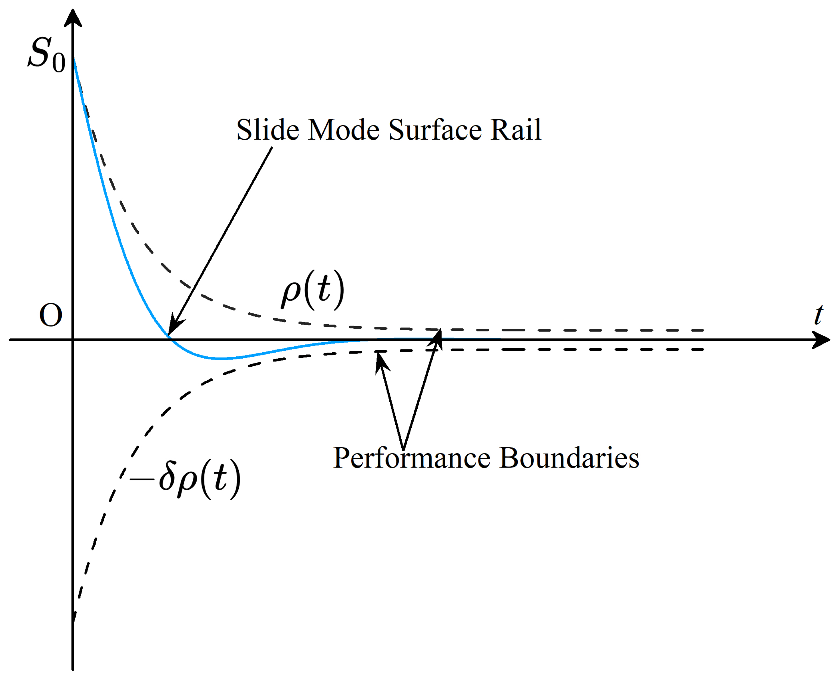
where s = s 1 s 2 s 3 s 4 s 5 T , s i i = 1 , 2 5 is the sliding-mode function, and E 1 and E 2 have been defined in (7). To constrain the evolution trajectory of the sliding-mode surface and the steady-state performance of the system, as shown in Figure 3, on the basis of the idea of prescribed performance control, the dynamic sliding-mode function is mapped as a direct object of performance mapping, and the expression of the performance function is defined as follows:
ρ i t = ρ 0 i ρ i e μ i t + ρ i i = 1 , 2 5
where ρ 0 i , ρ i and μ i are constants, μ i i = 1 , 2 5 is the convergence factor, ρ 0 i i = 1 , 2 5 is the initial value of the performance function, ρ i i = 1 , 2 5 is the steady state value of the performance function, lim t ρ i t = ρ i i = 1 , 2 5 . The function satisfies ρ i t < s i < ρ i t for the constraints on the sliding-mode function. The sliding-mode function can be mapped by designing the following transformation function:
S i = 1 2 ln 1 + s i / ρ i 1 s i / ρ i
where S i is the mapped sliding-mode function. To facilitate controller design, let S = S 1 S 2 S 3 S 4 S 5 T . The derivation of (19) yields:
S ˙ i = s ˙ i ρ i 1 + s i / ρ i 1 s i / ρ i
On the basis of the mapped sliding-mode function, considering the input saturation of the AUV and combining the optimal control principle, the value function is defined as
J S S , τ = 0 U S S , τ d s
where U S S , τ = S T Q 1 S + Φ τ , Φ ( τ ) = 0 τ 2 tanh T ( ϑ / γ ) γ R 1 d ϑ , γ is the boundary of τ and γ = diag γ 1 γ 2 γ 5 , γ | γ , Q 1 and R 1 are diagonal matrices with positive diagonal elements and Q 1 q 1 , R 1 r 1 , R 1 1 r 2 . The optimal value function is as follows:
J S * S * , τ * = min τ * Ψ ( Ω τ ) 0 U S S * , τ * d s
where S * is the value of the optimal sliding-mode function, τ * is the optimal control input, and Ψ ( Ω τ ) is a collection of permissive control strategies. To solve for τ * , the HJB equation is defined as
H = U S S , τ + J S / S T M K E 2 + E ˙ 2 = U S S , τ + J S / S T M F 1 E 2 + τ + μ
where M = diag M 1 M 2 M 5 , M i = 1 / ρ i 1 + s i / ρ i 1 s i / ρ i , and M m , F 1 = K + C S + D S and F 1 f 1 . Φ ( τ ) can be rewritten as
Φ ( τ ) = 0 τ 2 tanh T ( ϑ / γ ) γ R 1 d ϑ = 2 τ T γ R 1 tanh 1 τ γ + N T γ 2 ln I τ γ 2
where τ γ = τ / γ , τ γ 2 = τ 2 / γ 2 , γ 2 = diag γ 1 2 γ 2 2 γ 5 2 and γ 2 γ 2 , τ 2 = τ 1 2 τ 2 2 τ 5 2 T , N is the column vector consisting of the diagonal elements of R 1 , and the elements of I 5 × 1 are all 1. Since τ * satisfies H τ τ = τ * = 0 , a partial derivation of (23) solves for τ * as
τ * = γ tanh R ¯ J S * / 2 S
where R ¯ = γ 1 R 1 1 M T and R ¯ r 3 . According to the Weierstrass’ approximation theorem [32], a neural network is designed to approximate the optimal value function, assuming that J S * can be approximated by the following neural network:
J S * = W S * T ϕ ( S ) + δ ( S )
where W S * is the optimal weight of the neural network and W S * ϖ 1 , ϕ ( S ) is the basis function, δ ( S ) is the approximation error. According to (26), τ * can be rewritten as
τ * = γ tanh Θ *
where Θ * = R ¯ ϕ S T W S * + R ¯ δ S / 2 , ϕ S = ϕ ( S ) / S , δ S = δ ( S ) / S . Since W S * is unknown, the estimation of W S * is needed to obtain a usable control input, when W ^ S W S * , δ S 0 , i.e.,
τ = γ tanh Θ ^
where W ^ S is the estimation of W S * , Θ ^ = R ¯ ϕ S T W ^ S / 2 . To obtain the updating law for W ^ S , substituting (28) into (23) yields the HJB equation as
H ^ = S T Q 1 S + W ^ S T M ¯ F 1 E 2 + μ + N T γ 2 ln ϑ ^
where ϑ ^ = sech 2 R ¯ Θ ^ , M ¯ = ϕ S M . Since H * = 0 , the error between H ^ and H * = 0 is defined as H ^ H * = H ^ . To obtain the neural network update law, the following positive definite function is defined:
E S = 1 2 H ^ H * 2
According to (30), the updated law for neural network weights via the gradient descent method is as follows:
W ^ ˙ S = κ 1 E S W ^ S = κ 1 H ^ H ^ W ^ S = κ 1 H ^ ω
where ω = F ¯ E 2 + M ¯ μ γ M ¯ tanh Θ ^ , F ¯ = M ¯ F 1 , κ 1 = k 1 / 1 + ω T ω 2 , k 1 is a constant and k 1 > 0 .

3.3. Stability Analysis

In this section, the stability analysis of the controller designed in this paper is carried out. First, the Lyapunov function is defined as
V = J S * + 1 2 W ˜ S T W ˜ S
where W ˜ S = W S * W ^ S . Deriving V with respect to time yields:
V ˙ = J S * / S T S ˙ W ˜ S T W ^ ˙ S = J S * / S T M F 1 E 2 + τ + μ W ˜ S T W ^ ˙ S = J S * / S T M F 1 E 2 + τ * + μ J S * / S T τ ˜ W ˜ S T W ^ S
where τ ˜ = τ * τ . When W ˜ S is a small quantity, it is obtained according to the Taylor expansion principle and (27) and (28):
τ ˜ = γ R ¯ ϑ ^ ϕ S T W ˜ S + δ S / 2
Since ϑ ^ 1 , substituting (34) into (33), the following inequality holds:
V ˙ S T Q 1 S 2 τ * T γ R 1 tanh 1 τ * / γ N T γ 2 ln ϑ * + ϕ S T W S * + δ S T R 1 1 M T ϕ S T W ˜ S + δ S / 2 W ˜ S T W ^ ˙ S
where ϑ * = I τ * 2 / γ 2 . Rewrite (35) as follows:
V ˙ S T Q 1 S 2 τ * T γ R 1 tanh 1 τ * / γ N T γ 2 ln ϑ * + W S * T ϕ S R 1 1 M T ϕ S T W ˜ S / 2 + δ S T R 1 1 M T ϕ S T W ˜ S / 2 + W S * T ϕ S R 1 1 M T δ S / 2 + δ S T R 1 1 M T δ S / 2 W ˜ S T W ^ ˙ S
According to Young’s inequality [33], (36) can be rewritten as
V ˙ S T Q 1 S 2 τ * T γ R 1 tanh 1 τ * / γ N T γ 2 ln ϑ * + W S * T ϕ S ϕ ¯ W S * / 4 + W ˜ S T ϕ S ϕ ¯ W ˜ S / 4 + δ S T ϕ ¯ δ S / 2 W ˜ S T W ^ ˙ S
where ϕ ¯ = R 1 1 M T ϕ S T + R 1 1 M T .
Theorem 1
([34]). The activation function and approximation error, and their gradients of the neural network are bounded, i.e., σ ( x ) σ 1 , σ x σ 2 , ε ( x ) ε 1 , and ε x ε 2 .
According to Young‘s inequality and Theorem 1, the following can be obtained:
W S * T ϕ S ϕ ¯ W S * 4 κ 2 W ˜ S T ϕ S ϕ ¯ W ˜ S 4 κ 3 W ˜ S 2 δ S T ϕ ¯ δ S 2 κ 4
where κ 2 = r 2 m σ 2 2 + r 2 m σ 2 ϖ 1 2 / 4 , κ 3 = r 2 m σ 2 2 + r 2 m σ 2 / 4 , and κ 4 = r 2 m σ 2 + r 2 m ε 2 2 / 2 . Substituting (38) into (37) yields:
V ˙ S T Q 1 S 2 τ * T γ R 1 tanh 1 τ * / γ N T γ 2 ln ϑ * + κ 2 + κ 3 W ˜ S 2 + κ 4 W ˜ S T W ^ ˙ S
Substituting (31) into (39) yields
V ˙ S T Q 1 S 2 τ * T γ R 1 tanh 1 τ * / γ N T γ 2 ln ϑ * + κ 2 + κ 3 W ˜ S 2 + κ 4 + κ 1 W ˜ S T W ^ S T F ¯ E 2 ω + κ 1 W ˜ S T W ^ S T M ¯ μ ω + κ 1 W ˜ S T S T Q 1 S ω + κ 1 W ˜ S T N T γ 2 ln ϑ ^ ω
Substituting ω = F ¯ E 2 + M ¯ μ γ M ¯ tanh R ¯ Θ ^ into (40) yields
V ˙ S T Q 1 S 2 τ * T γ R 1 tanh 1 τ * / γ N T γ 2 ln ϑ * + κ 2 + κ 3 W ˜ S 2 + κ 4 + κ 1 W ˜ S T S T Q 1 S F ¯ E 2 κ 1 W ˜ S T S T Q 1 S γ M ¯ tanh R ¯ Θ ^ + κ 1 W ˜ S T N T γ 2 ln ϑ ^ F ¯ E 2 + κ 1 W ˜ S T N T γ 2 ln ϑ ^ M ¯ μ κ 1 W ˜ S T N T γ 2 ln ϑ ^ γ M ¯ tanh R ¯ Θ ^ + κ 1 W ˜ s T W ^ s T F ¯ E 2 F ¯ E 2 + κ 1 W ˜ s T W ^ s T M ¯ μ M ¯ F 1 E 2 + κ 1 W ˜ s T W ^ s T F ¯ E 2 M ¯ μ + κ 1 W ˜ s T W ^ s T M ¯ μ M ¯ μ κ 1 W ˜ s T W ^ s T F ¯ E 2 γ M ¯ tanh R ¯ Θ ^ κ 1 W ˜ s T W ^ s T M ¯ μ γ M ¯ tanh R ¯ Θ ^
Substituting W ^ S = W S * W ˜ S into (41), from S T Q 1 S q 1 S 2 yields
V ˙ S T Q 1 S 2 τ * T γ R 1 tanh 1 τ * / γ N T γ 2 ln ϑ * + κ 2 + κ 3 W ˜ S 2 + κ 4 + κ 1 W ˜ S T N T γ 2 ln ϑ ^ γ M ¯ tanh R ¯ Θ ˜ + κ 1 q 1 S 2 W ˜ S T F ¯ 1 E 2 + κ 1 q 1 S 2 W ˜ S T M ¯ μ + κ 1 q 1 S 2 W ˜ S T γ M ¯ tanh R ¯ Θ ˜ + κ 1 W ˜ S T N T γ 2 ln ϑ F ¯ 1 E 2 + κ 1 W ˜ S T N T γ 2 ln ϑ M ¯ μ + κ 1 W ˜ S T W S * T F ¯ E 2 F ¯ E 2 + κ 1 W ˜ S T W S * T F ¯ E 2 M ¯ μ + κ 1 W ˜ S T W S * T M ¯ μ F ¯ 1 E 2 + κ 1 W ˜ S T W S * T M ¯ μ M ¯ μ κ 1 W ˜ S T W ˜ S T F ¯ E 2 F ¯ E 2 κ 1 W ˜ S T W ˜ S T F ¯ E 2 M ¯ μ κ 1 W ˜ S T W ˜ S T M ¯ μ F ¯ E 2 κ 1 W ˜ S T W ˜ S T M ¯ μ M ¯ μ + κ 1 W ˜ S T W S * T F ¯ E 2 γ M ¯ tanh R ¯ Θ ˜ + κ 1 W ˜ S T W ˜ S * T M ¯ μ γ M ¯ tanh R ¯ Θ ˜ + κ 1 W ˜ S T W ˜ S T F ¯ E 2 γ M ¯ tanh R ¯ Θ ˜ + κ 1 W ˜ S T W ˜ S T M ¯ μ γ M ¯ tanh R ¯ Θ ˜
where Θ ˜ = ϕ S T W S * W ˜ S / 2 . According to Young’s inequality, the following inequality holds:
N T γ 2 ln ϑ ^ κ 5 W ˜ S T γ M ¯ tanh R ¯ Θ ˜ κ 6 1 + W ˜ S 2 W ˜ S T F ¯ E 2 κ 7 W ˜ S 2 + E 2 2 W ˜ S T M ¯ μ κ 8 W ˜ S 2 + μ 2 W S * T F ¯ E 2 κ 7 ϖ 1 2 + E 2 2 W S * T M ¯ μ κ 8 ϖ 1 2 + μ 2 κ 9 = N T γ 2 ln ϑ * 0
where κ 5 = γ 2 r 1 2 + 4 γ 2 / 2 , κ 6 = γ m σ 2 / 2 , κ 7 = m f 1 σ 2 / 2 , κ 8 = m σ 2 / 2 . Substituting (43) into (42), according to Young’s inequality, yields
V ˙ S T Q 1 S 2 τ * T γ R 1 tanh 1 τ * / γ + κ 9 + κ 2 + κ 3 W ˜ S 2 + κ 4 + κ 1 κ 5 κ 6 1 + W ˜ S 2 + κ 1 κ 7 q 1 S 2 W ˜ S 2 + E 2 2 + κ 1 q 1 κ 8 S 2 W ˜ S 2 + μ 2 + κ 1 q 1 κ 6 S 2 1 + W S 2 + κ 1 κ 5 κ 7 W ˜ S 2 + E 2 2 + κ 1 κ 5 κ 8 W ˜ S 2 + μ 2 + κ 1 κ 7 2 W ˜ S 4 + ϖ 1 2 W ˜ S 2 + 3 E 2 2 W ˜ S 2 + ϖ 1 2 E 2 2 + 2 E 2 4 + κ 1 κ 7 κ 8 2 W ˜ S 4 + 2 ϖ 1 2 W ˜ S 2 + 3 E 2 2 W ˜ S 2 + ϖ 1 2 μ 2 + κ 1 κ 7 κ 8 4 E 2 2 μ 2 + 3 μ 2 W ˜ S 2 + ϖ 1 2 E 2 2 + κ 1 κ 8 2 W ˜ S 4 + ϖ 1 2 W ˜ S 2 + 3 μ 2 W ˜ S 2 + ϖ 1 2 μ 2 + 2 μ 4 + κ 1 κ 6 κ 7 ϖ 1 2 + ϖ 1 2 W ˜ S 2 + 2 E 2 2 + 2 E 2 2 W ˜ S 2 + W ˜ S 2 + W ˜ S 4 + κ 1 κ 6 κ 8 ϖ 1 2 + ϖ 1 2 W ˜ S 2 + 2 μ 2 + 2 μ 2 W ˜ S 2 + W ˜ S 2 + W ˜ S 4
Rewrite (44) as
V ˙ S T Q 1 S 2 τ * T γ R 1 tanh 1 τ * / γ + β 1 W ˜ S 4 + β 2 W ˜ S 2 + β 3
where
β 1 = κ 1 κ 8 2 + κ 1 κ 6 κ 8 + κ 1 κ 6 κ 7 + κ 1 κ 7 2 + 2 κ 1 κ 7 κ 8
β 2 = κ 3 + κ 1 κ 5 κ 6 + κ 1 κ 7 q 1 S 2 + κ 1 q 1 κ 6 S 2 + κ 1 κ 5 κ 7 + κ 1 κ 5 κ 8 + κ 1 κ 7 2 ϖ 1 2 + 3 κ 1 κ 7 2 E 2 2 + κ 1 κ 8 2 ϖ 1 2 + κ 1 κ 8 2 μ 2 + 2 κ 1 κ 7 κ 8 ϖ 1 2 + 3 κ 1 κ 7 κ 8 E 2 2 + 3 κ 1 κ 7 κ 8 μ 2 + κ 1 q 1 κ 8 S 2 + 2 κ 1 κ 8 2 μ + κ 1 κ 6 κ 7 ϖ 1 2 + 2 κ 1 κ 6 κ 7 E 2 2 + κ 1 κ 6 κ 8 ϖ 1 2 + 2 κ 1 κ 6 κ 8 μ 2 + κ 1 κ 6 κ 7 + κ 1 κ 6 κ 8
β 3 = κ 9 + κ 2 + κ 4 + κ 1 κ 5 κ 6 + κ 1 κ 7 q 1 S 2 E 2 2 + κ 1 q 1 κ 8 S 2 μ 2 + κ 1 q 1 κ 6 S 2 + κ 1 κ 5 κ 7 E 2 2 + κ 1 κ 5 κ 8 μ 2 + κ 1 κ 7 2 ϖ 1 2 E 2 2 + κ 1 κ 7 κ 8 ϖ 1 2 μ 2 + κ 1 κ 7 κ 8 ϖ 1 2 E 2 2 + κ 1 κ 8 2 ϖ 1 2 μ 2 + 2 κ 1 κ 8 2 μ 4 + 2 κ 1 κ 7 2 E 2 4 + 4 κ 1 κ 7 κ 8 μ 2 E 2 2 + κ 1 κ 6 κ 7 ϖ 1 2 + 2 κ 1 κ 6 κ 7 E 2 2 + κ 1 κ 6 κ 8 ϖ 1 2 + 2 κ 1 κ 6 κ 8 μ 2
Substituting (27) into (45) yields
V ˙ S T Q 1 S 2 tanh T Θ * γ 2 R 1 Θ * + β 1 W ˜ S 4 + β 2 W ˜ S 2 + β 3 λ min Q 1 S 2 λ min 2 γ 2 R 1 tanh R ¯ Θ * 2 + β 1 W ˜ S 4 + β 2 W ˜ S 2 + β 3
where λ min ( · ) denotes the minimum eigenvalue. The augmentation vector is deefined as Γ = S tanh Θ * W ˜ S 2 T , and then (49) can be written in vector form as
V ˙ Γ T P Γ + L Γ + β 3 λ min P Γ 2 + β 2 Γ + β 3
where P = diag λ min Q 1 λ min 2 γ 2 R 1 β 1 , L = 0 0 β 2 . By applying Lyapunov stability theory, according to (50), the closed-loop control system is uniformly and ultimately boundedly stable and that the augmentation state vector Γ will converge to a neighborhood containing the stable equilibrium point with a neighborhood radius
r 4 = β 2 + β 2 2 + 4 β 3 λ min P 2 λ min P
Since the radius of the neighborhood can be made arbitrarily small by choosing the appropriate parameters, and the approximation error can be guaranteed to be arbitrarily small by choosing the appropriate basis functions and dimensions for the critic neural network and the intelligent controller can approximate the ideal optimal control policy with arbitrary accuracy.

4. Simulation Test

In this section, the superiority of the method proposed in this paper is verified through simulation, using the conventional single critic neural network ADP method based on state error as a comparison. During the actual underwater recovery process, AUV-M acts as the object to be recovered and moves under a fixed input. Its state response serves as the reference for AUV-S. At the same time, a zero error is taken as the criterion for successful recovery. Therefore, in the simulation, we assume that the input for AUV-M is τ M = 1 1 1 1 1 T . In the simulation, the total simulation duration is set to 200 s, the sampling interval is 0.01 s, the integration method is fourth-order Runge–Kutta, and the tolerance of the solver was set to 1 × 10⁻⁶. The initial state of AUV-M is η M init = 2 2 2 0 0 T and ν M init = 0 0 0 0 0 T . The initial state of AUV-S is η S init = 0 0 0 0 0 T and ν S init = 0 0 0 0 0 T . The neural network basis function is ϕ S = S 1 2 S 2 2 S 3 2 S 4 2 S 5 2 T , the neural network learning law for the conventional ADP method is 0.5, the initial value of the weights is W init = 5 I 10 × 1 , σ E = 5 E 1 ( i ) 2 2 + E 2 ( i ) 2 2 , , E 1 ( i ) E 2 ( i ) T i = 1 , 2 5 , k 1 = 0.5 , Q = I 10 × 10 , R = I 5 × 5 , Q 1 = I 5 × 5 , R 1 = I 5 × 5 , γ = diag 10 10 10 5 5 , K = I 5 × 5 , ρ 0 i = 3 i = 1 , 2 5 , ρ i = 0.2 i = 1 , 2 5 , μ i = 0.5 i = 1 , 2 5 , the initial values of the neural network weights are W S init = 5 I 5 × 1 , τ M = 1 1 1 1 1 T , and the model parameters of AUV-M and AUV-S are shown in Table 1 and Table 2:
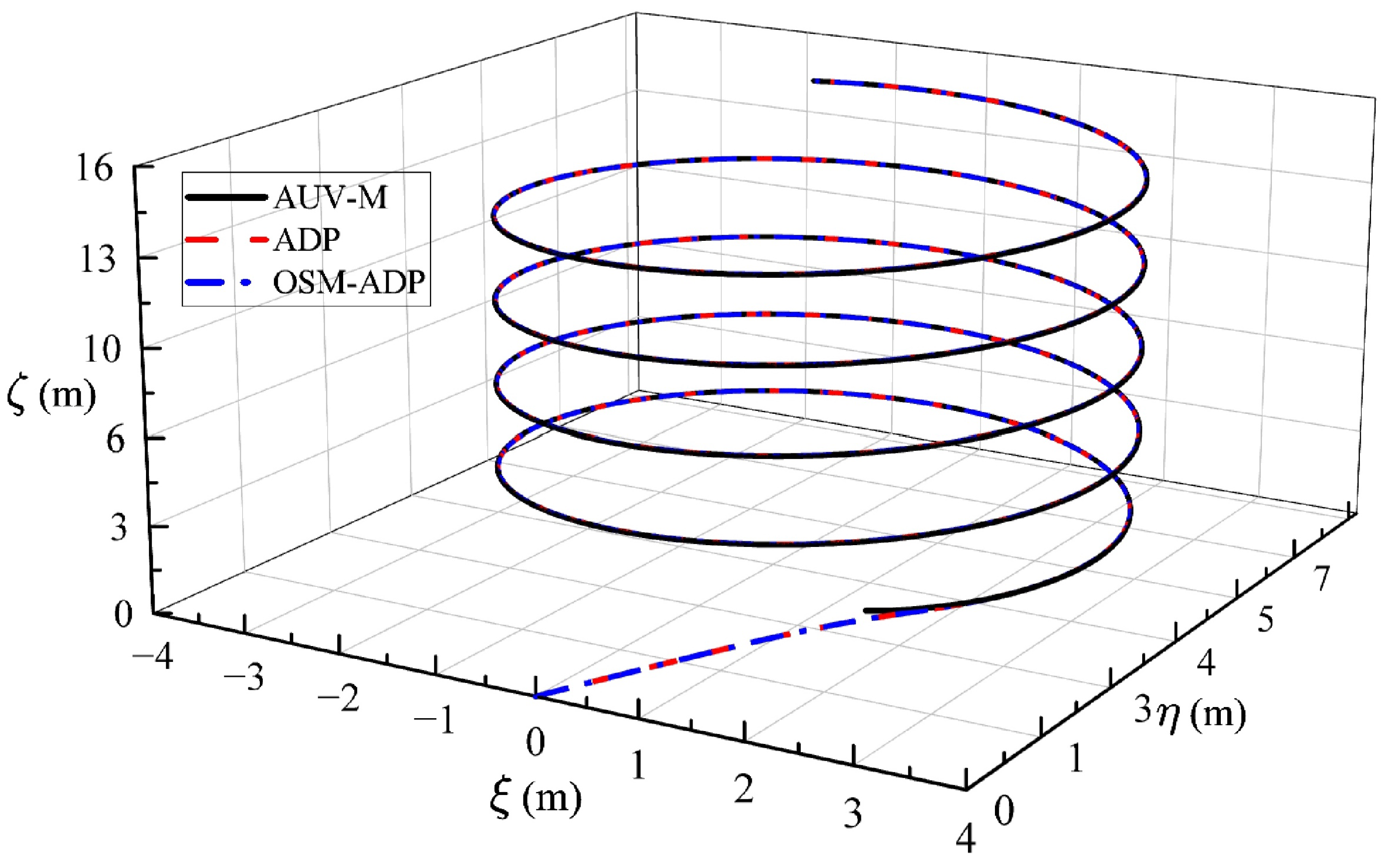
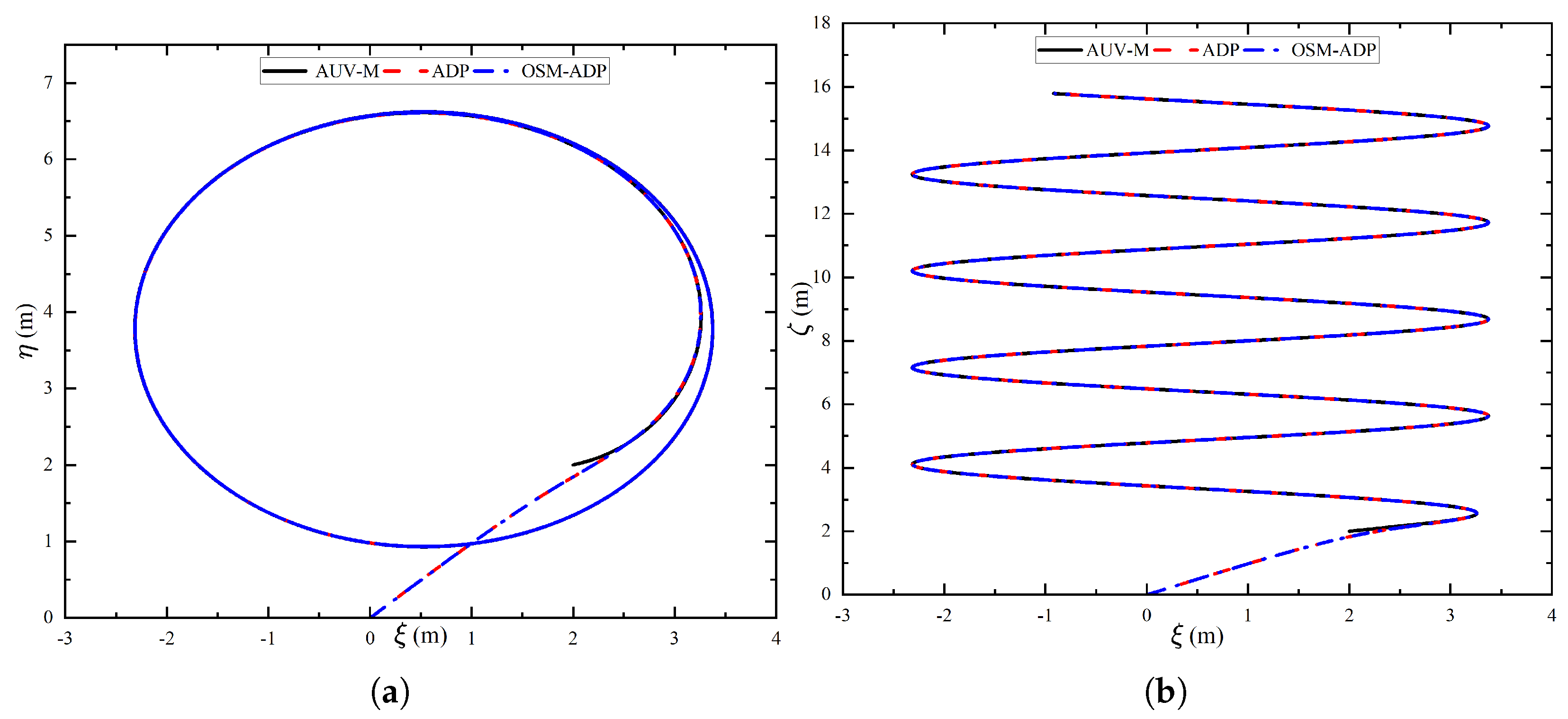
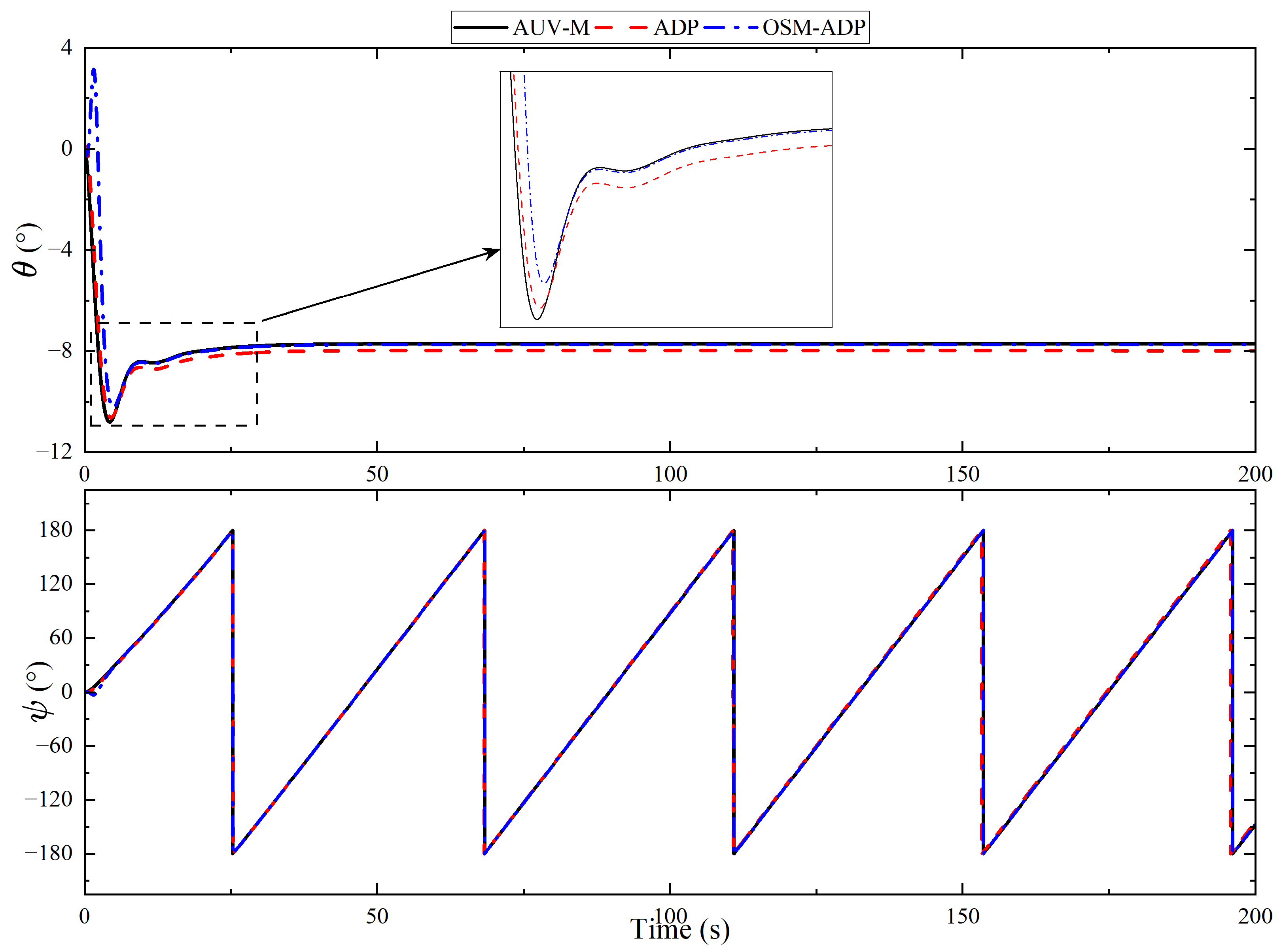
The three-dimensional trajectories of AUV-S reaching synchronization with the state of AUV-M and the position changes in ξ η and ξ ζ plane under the control of the OSM-ADP method proposed in this paper and the conventional ADP method are shown in Figure 4 and Figure 5. To highlight the superiority of the method proposed in this paper, the changes in the state of the AUV-S over time under different methods are analyzed in an expanded manner, as shown in Figure 6 and Figure 7. Figure 6 and Figure 7 show that the OSM-ADP method proposed in this paper reflects significant advantages in terms of accuracy and convergence speed compared with the conventional ADP method. In particular, in pitch angle control, the conventional ADP method results in a steady-state error that cannot be eliminated, whereas the OSM-ADP method results in a sufficiently small pitch error.
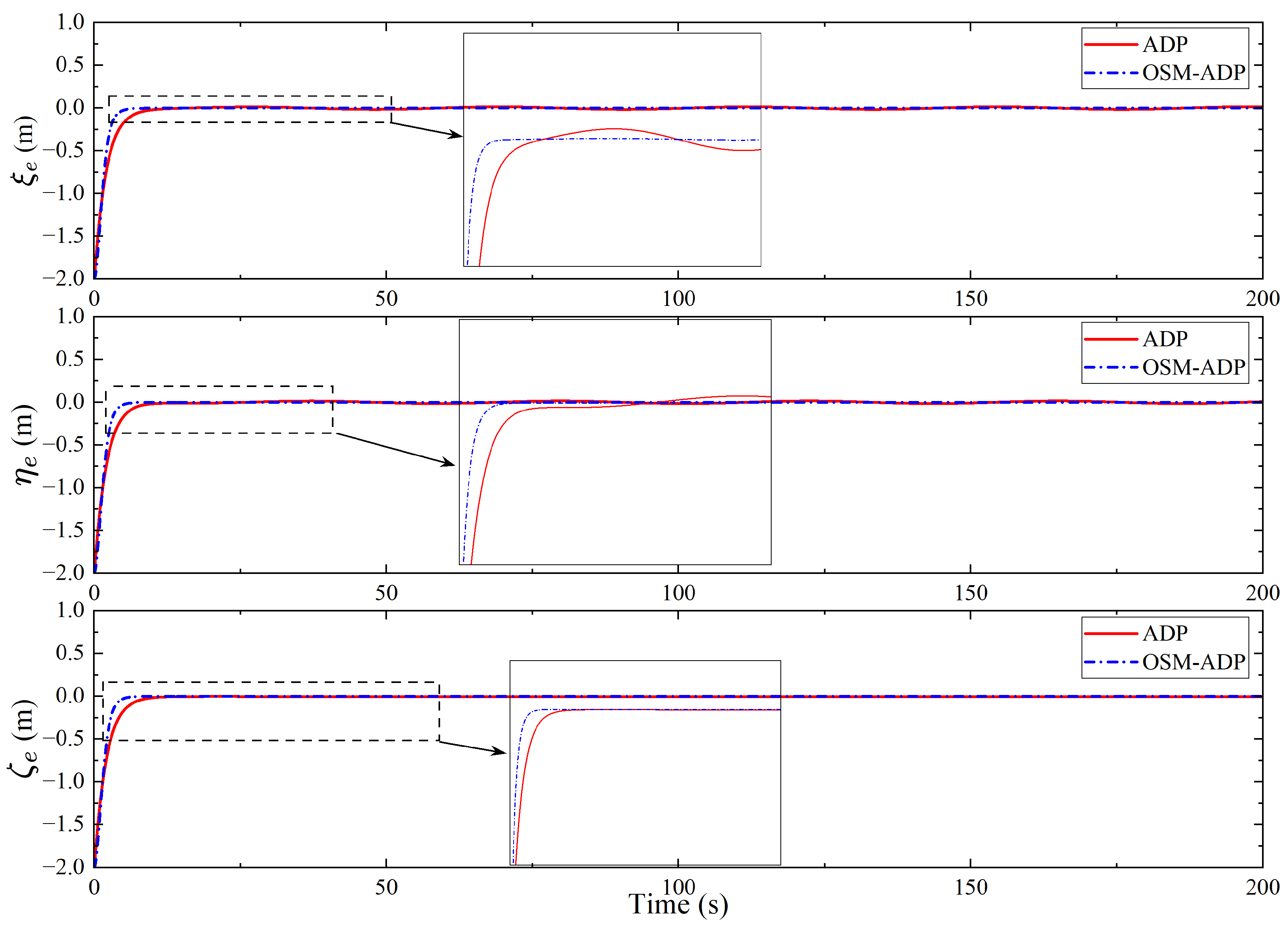
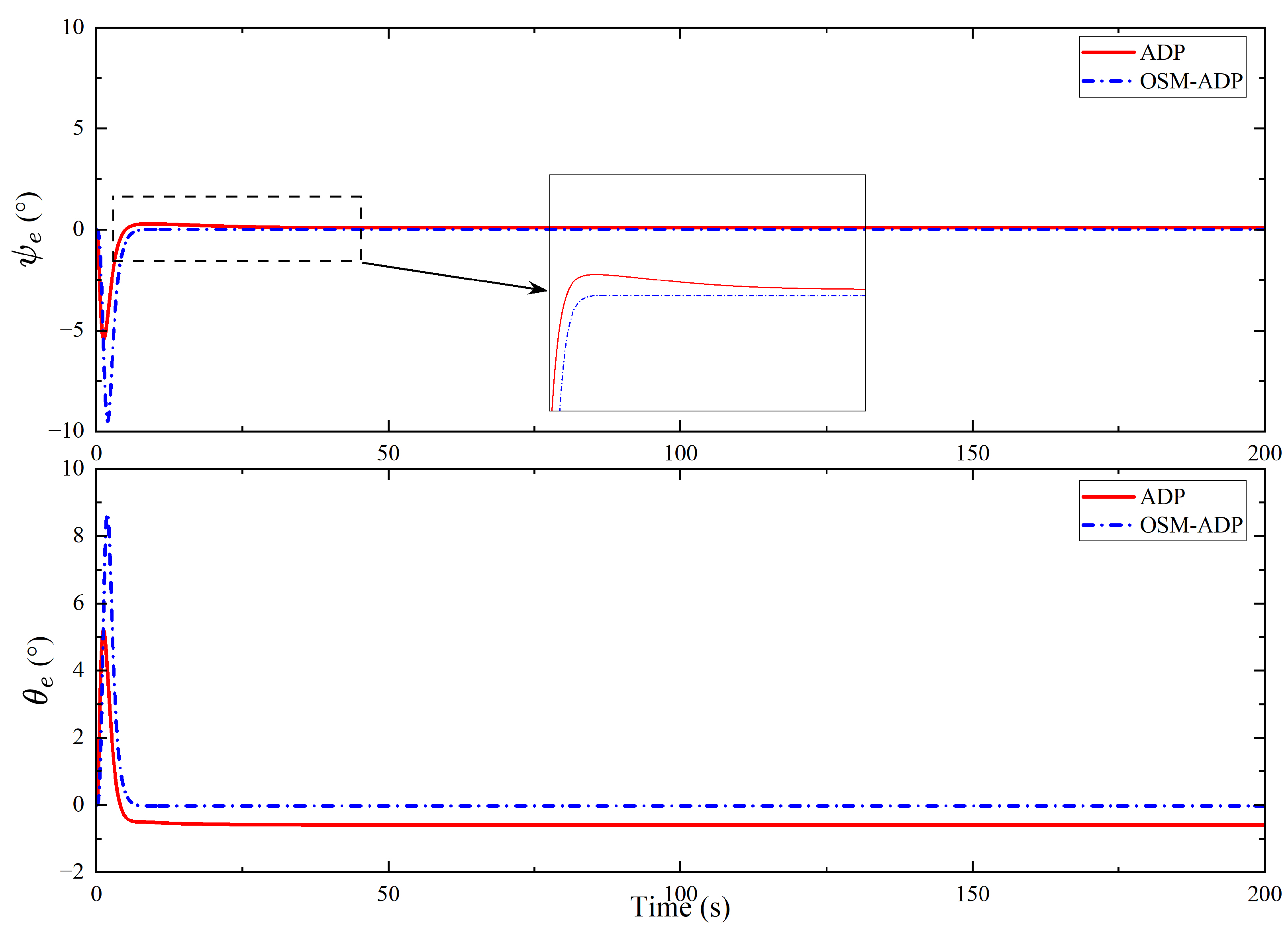
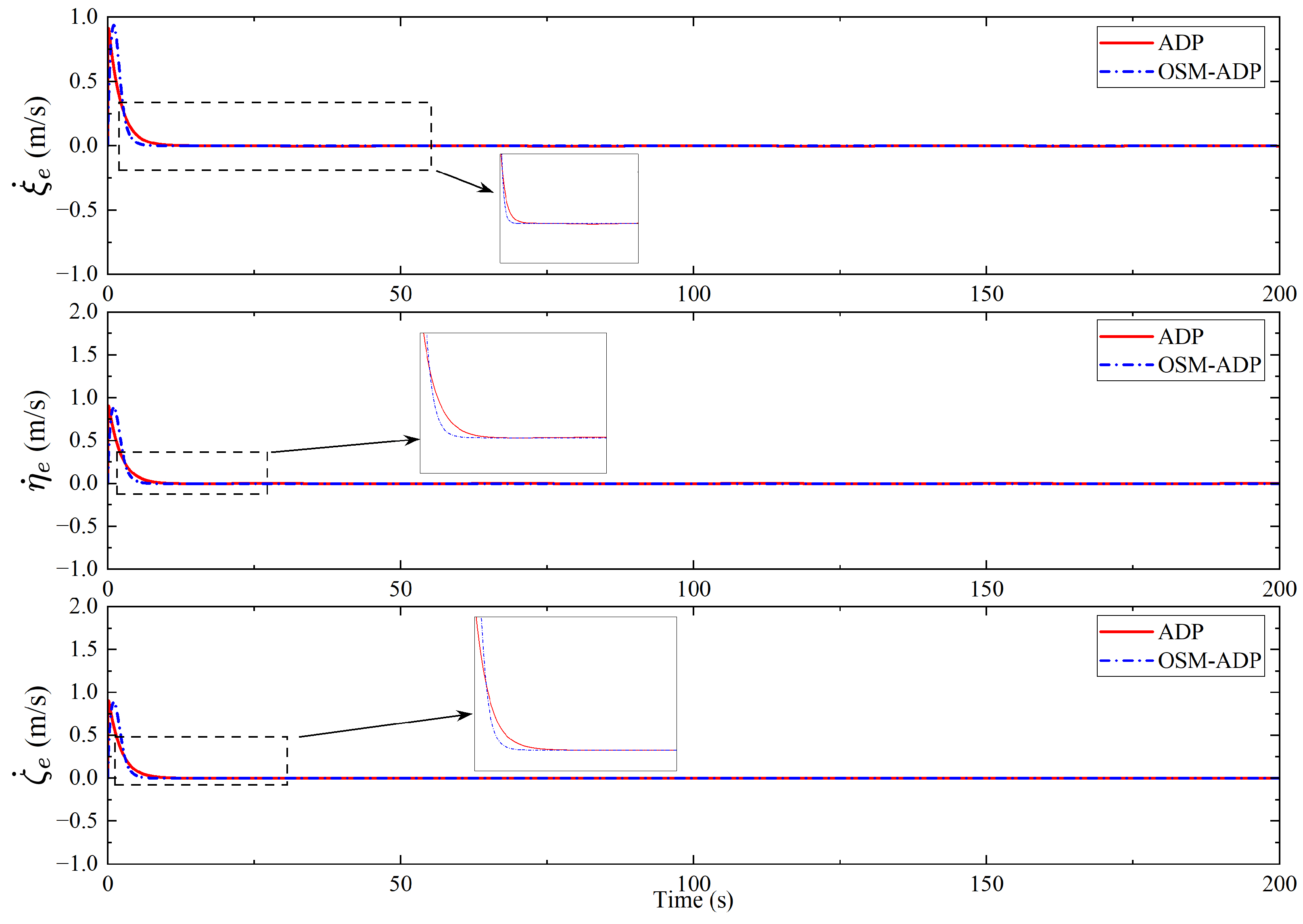
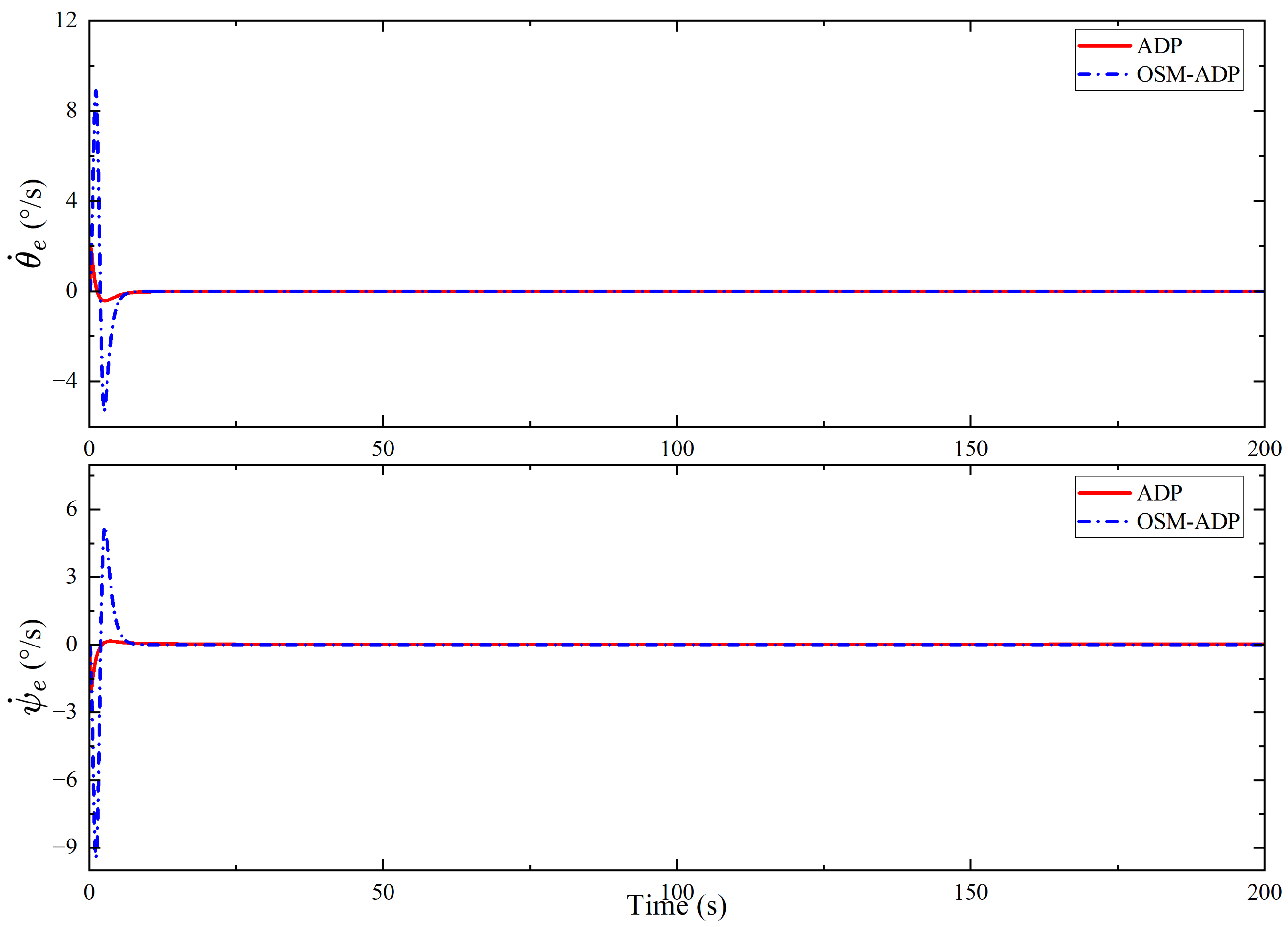
The responses of the position error and attitude error and their derivatives are shown in Figure 8, Figure 9, Figure 10 and Figure 11, respectively. Figure 8 and Figure 9 show that the OSM-ADP method proposed in this paper is able to converge the errors faster than the conventional ADP method. In the directions ξ , η , and θ , the conventional ADP method causes ξ e and η e to fluctuate around zero, whereas θ e has a steady-state error of approximately 0 . 5 . In terms of accuracy, the method proposed in this paper also has obvious advantages.
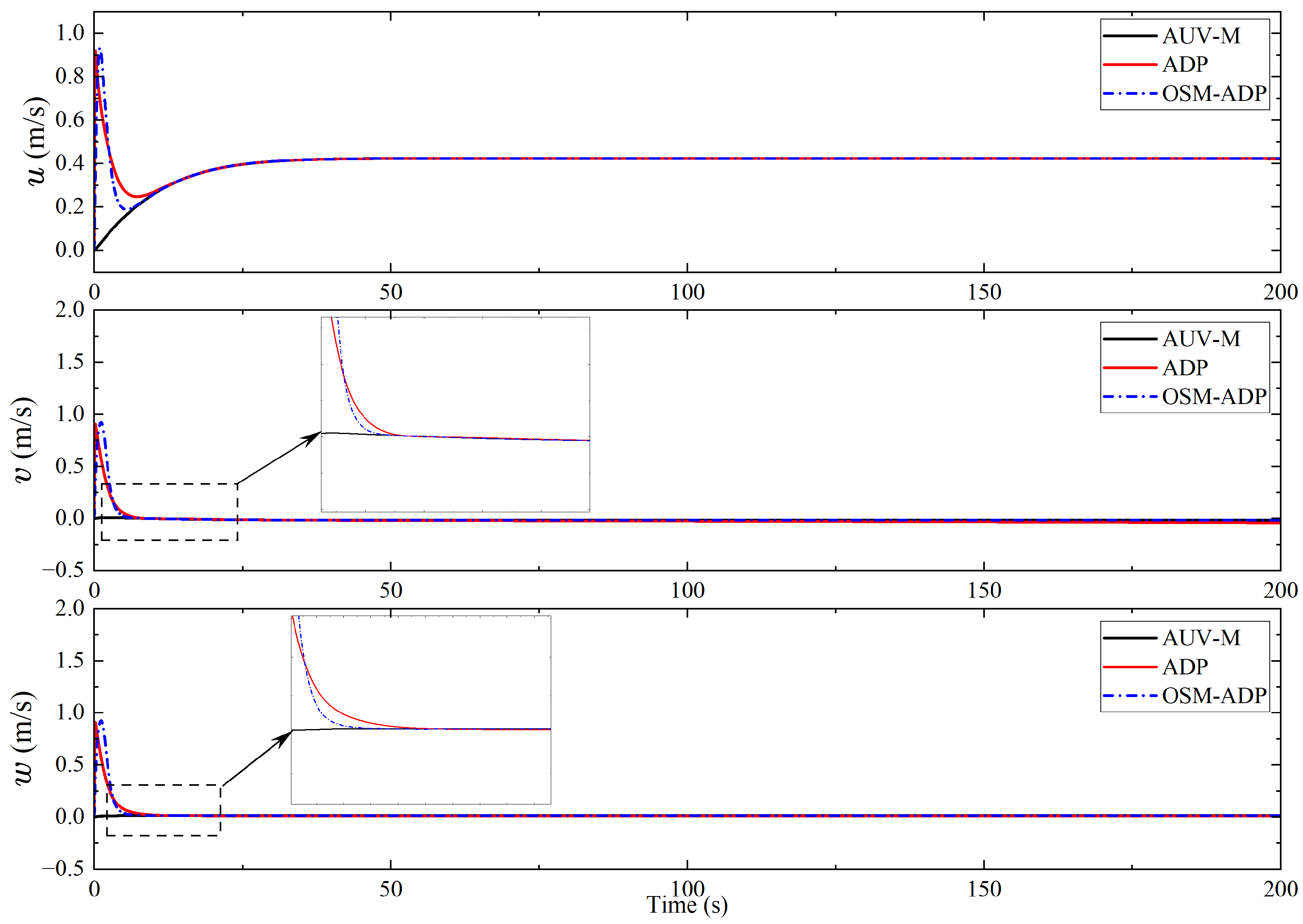
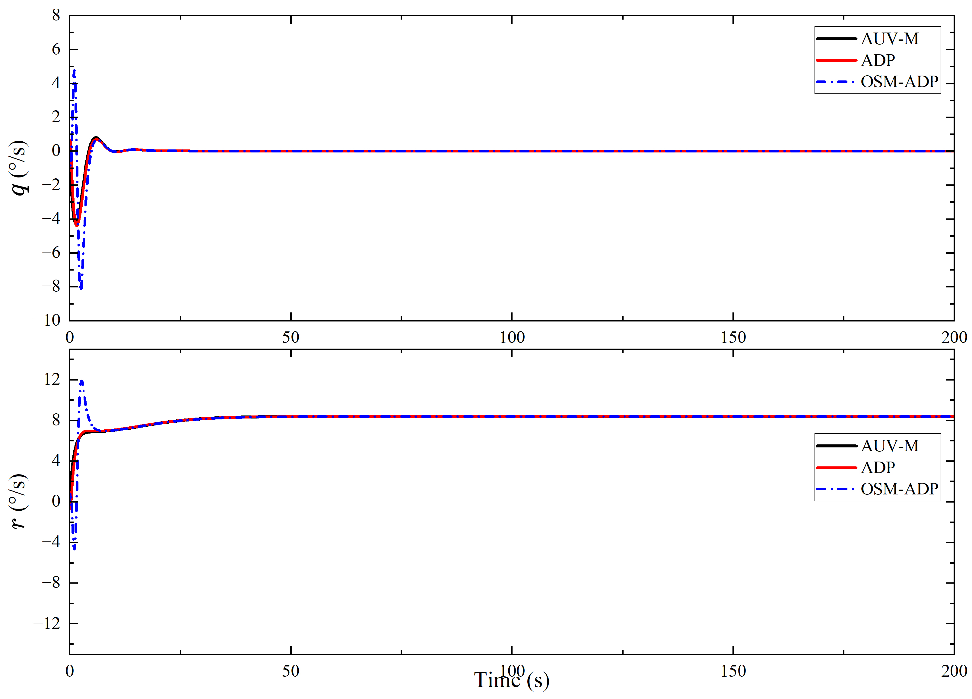
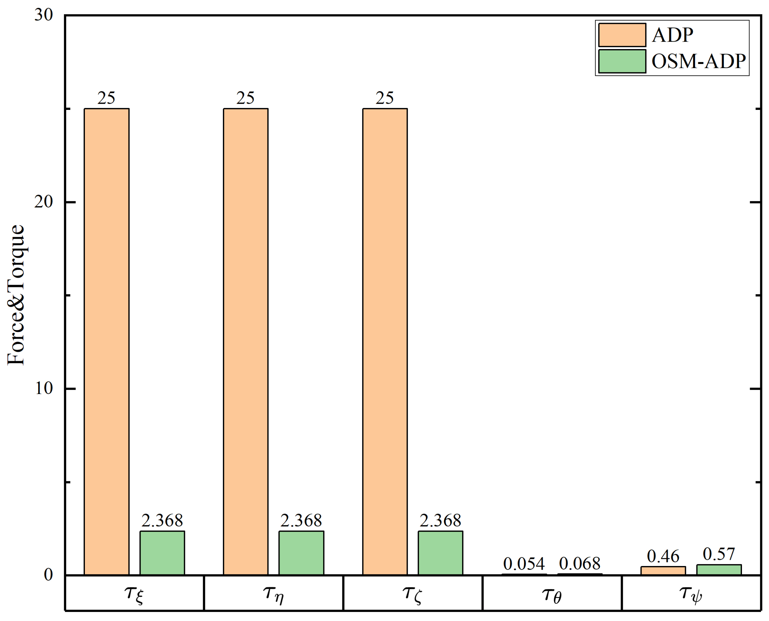
The velocity and angular velocity responses of AUV-S and AUV-M are shown in Figure 12 and Figure 13. In terms of velocity, the OSM-ADP method proposed in this paper is faster in synchronize the AUV-S with AUV-M. In terms of the angular velocity response, the method proposed in this paper has a faster response. The control forces and torque applied to the AUV-S are compared in Figure 14 and Figure 15, and the method proposed in this paper produces a smaller control input. Figure 15 shows that the conventional ADP method does not eliminate the error although it is no longer updated in the presence of steady-state error and is not zero. The maximum specific values of force and torque are compared as shown in Figure 16.
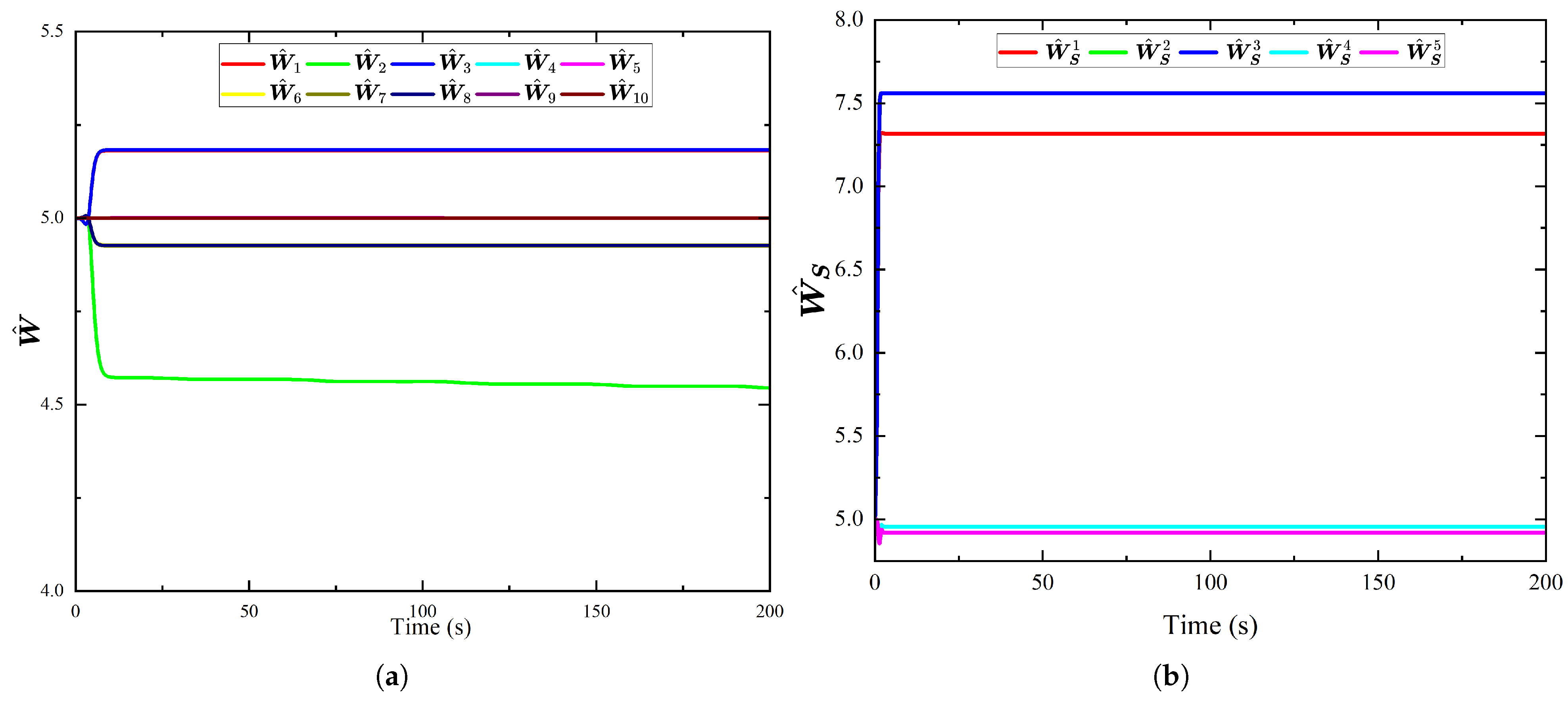
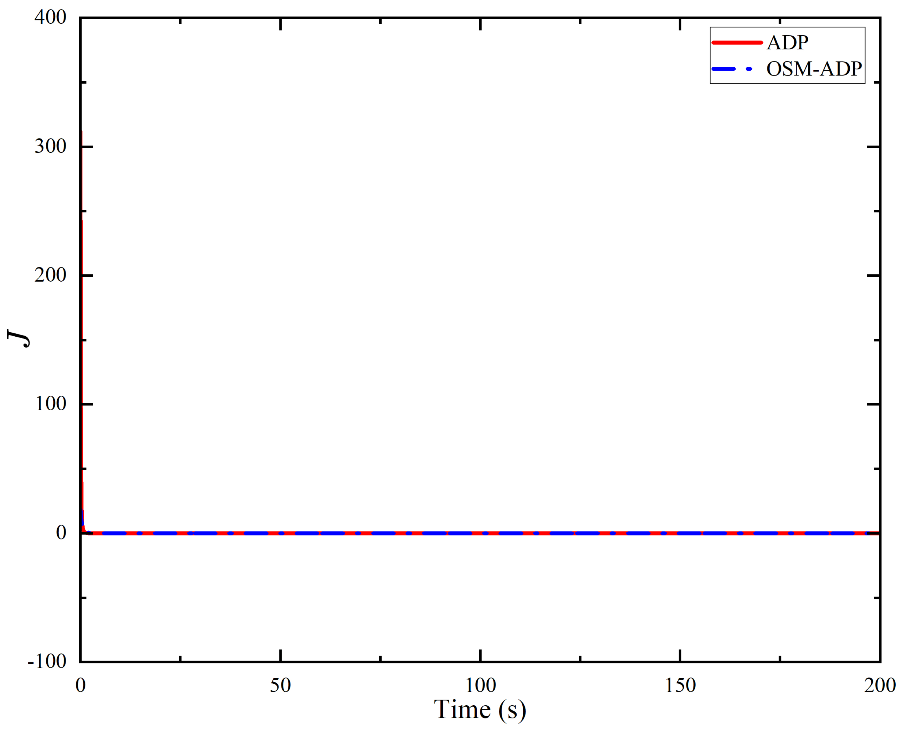
The neural network weight updates of the conventional ADP method and the OSM-ADP method proposed in this paper are shown in Figure 17. The method proposed in this paper needs to update only five weights to complete the control process, which effectively reduces the computational resources occupied by the neural network weight update. In Figure 18, the optimization process of the value function is shown, and the method proposed in this paper significantly reduces the initial value of the value function compared with the conventional ADP method and also optimizes the convergence value. A comparison between the initial and final values of the value function is given in Table 3.
The constraints of the OSM-ADP method proposed in this paper on the evolutionary trajectory of the sliding-mode function are shown in Figure 19. Under the constraints of the performance boundary, the sliding-mode function can be well stabilized from the initial value to zero, showing good convergence properties.

5. Conclusions

In this paper, an optimal-sliding-mode-based ADP control method is proposed for the dynamic recovery master–slave synchronous control of AUVs under input saturation and performance constraints. The following results are achieved through theoretical analysis and simulation validation: First, the joint optimization of the state error and its derivatives is realized through the embedding of the dynamic characteristics of the sliding mode in the design of the value function, and the control response speed is significantly improved. Second, the combination of the prescribed performance function to constrain the evolution trajectory of the sliding-mode surface ensures that transient overshooting is suppressed and that the steady-state accuracy is considered. Finally, the tanh function is introduced to reconstruct the value function, thus avoiding the risk of input saturation and the hysteresis effect of the conventional anti-saturation compensator while also simplifying the controller structure. In the context of the input saturation and performance constraints, the position and attitude synchronization errors of the proposed method exhibit a faster convergence rate, higher steady-state accuracy, and smoother control force/torque. Compared with the conventional ADP method, the method proposed in this paper guarantees convergence speed and accuracy while concurrently minimizing the computational demands of control inputs and updating neural network weights. The method proposed in this paper provides a new concept for the master–slave synchronous control of AUVs. Meanwhile, it offers a new combination approach for preset performance mapping, the sliding-mode control method, and the ADP control method.

Author Contributions

Methodology, Y.S.; Software, F.G.; Investigation, W.W.; Writing—original draft, P.C.; Writing—review & editing, Z.X. All authors have read and agreed to the published version of the manuscript.

Funding

This research received no external funding.

Data Availability Statement

The original contributions presented in this study are included in the article. Further inquiries can be directed to the corresponding authors.

Conflicts of Interest

The authors declare no conflicts of interest.

References

  1. Alghamdi, R.; Dahrouj, H.; Al-Naffouri, T.Y.; Alouini, M.S. Toward immersive underwater cloud-enabled networks: Prospects and challenges. IEEE BITS Inf. Theory Mag. 2023, 3, 54–66. [Google Scholar] [CrossRef]
  2. Wang, L.; Zhu, D.; Pang, W.; Zhang, Y. A survey of underwater search for multi-target using Multi-AUV: Task allocation, path planning, and formation control. Ocean Eng. 2023, 278, 114393. [Google Scholar] [CrossRef]
  3. Sarda, E.I.; Dhanak, M.R. A USV-based automated launch and recovery system for AUVs. IEEE J. Ocean. Eng. 2016, 42, 37–55. [Google Scholar] [CrossRef]
  4. Sarda, E.I.; Dhanak, M.R. Launch and recovery of an autonomous underwater vehicle from a station-keeping unmanned surface vehicle. IEEE J. Ocean. Eng. 2018, 44, 290–299. [Google Scholar] [CrossRef]
  5. Szczotka, M. AUV launch & recovery handling simulation on a rough sea. Ocean Eng. 2022, 246, 110509. [Google Scholar] [CrossRef]
  6. Yazdani, A.M.; Sammut, K.; Yakimenko, O.; Lammas, A. A survey of underwater docking guidance systems. Robot. Auton. Syst. 2020, 124, 103382. [Google Scholar] [CrossRef]
  7. Zimmerman, R.; D’Spain, G.; Chadwell, C.D. Decreasing the radiated acoustic and vibration noise of a mid-size AUV. IEEE J. Ocean. Eng. 2005, 30, 179–187. [Google Scholar] [CrossRef]
  8. Fukasawa, T.; Noguchi, T.; Kawasaki, T.; Baino, M. “MARINE BIRD”, a new experimental AUV with underwater docking and recharging system. In Proceedings of the Oceans 2003. Celebrating the Past… Teaming Toward the Future (IEEE Cat. No. 03CH37492), San Diego, CA, USA, 22–26 September 2003; IEEE: Piscataway, NJ, USA, 2003; Volume 4, pp. 2195–2200. [Google Scholar]
  9. Kawasaki, T.; Noguchi, T.; Fukasawa, T.; Hayashi, S.; Shibata, Y.; Limori, T.; Okaya, N.; Fukui, K.; Kinoshita, M. “Marine Bird”, a new experimental AUV-results of docking and electric power supply tests in sea trials. In Proceedings of the Oceans’ 04 MTS/IEEE Techno-Ocean’04 (IEEE Cat. No. 04CH37600), Kobe, Japan, 9–12 November 2004; IEEE: Piscataway, NJ, USA, 2004; Volume 3, pp. 1738–1744. [Google Scholar]
  10. Allen, B.; Austin, T.; Forrester, N.; Goldsborough, R.; Kukulya, A.; Packard, G.; Purcell, M.; Stokey, R. Autonomous docking demonstrations with enhanced REMUS technology. In Proceedings of the OCEANS 2006, Boston, MA, USA, 18–21 September 2006; IEEE: Piscataway, NJ, USA, 2006; pp. 1–6. [Google Scholar]
  11. Palomeras, N.; Ridao, P.; Ribas, D.; Vallicrosa, G. Autonomous I-AUV docking for fixed-base manipulation. IFAC Proc. Vol. 2014, 47, 12160–12165. [Google Scholar] [CrossRef]
  12. Palomeras, N.; Vallicrosa, G.; Mallios, A.; Bosch, J.; Vidal, E.; Hurtos, N.; Carreras, M.; Ridao, P. AUV homing and docking for remote operations. Ocean Eng. 2018, 154, 106–120. [Google Scholar] [CrossRef]
  13. Sun, Y.; Cao, J.; Li, Y.; An, L.; Wang, Y. AUV Dynamic Docking Based on Longitudinal Safety Speed. In Proceedings of the 2018 Chinese Automation Congress (CAC), Xi’an, China, 30 November–2 December 2018; IEEE: Piscataway, NJ, USA, 2018; pp. 80–84. [Google Scholar]
  14. Yan, Z.; Xu, D.; Chen, T.; Zhou, J.; Wei, S.; Wang, Y. Modeling, strategy and control of UUV for autonomous underwater docking recovery to moving platform. In Proceedings of the 2017 36th Chinese Control Conference (CCC), Dalian, China, 26–28 July 2017; IEEE: Piscataway, NJ, USA, 2017; pp. 4807–4812. [Google Scholar]
  15. Yan, Z.; Hao, B.; Liu, Y.; Hou, S. Movement Control in Recovering UUV Based on Two-Stage Discrete T-S Fuzzy Model. Discret. Dyn. Nat. Soc. 2014, 2014, 362787. [Google Scholar] [CrossRef]
  16. Xu, J.; Wang, M.; Zhang, G. Trajectory tracking control of an underactuated unmanned underwater vehicle synchronously following mother submarine without velocity measurement. Adv. Mech. Eng. 2015, 7, 1687814015595340. [Google Scholar] [CrossRef]
  17. Du, X.; Wu, W.; Zhang, W.; Hu, S. Research on UUV recovery active disturbance rejection control based on LMNN compensation. Int. J. Control. Autom. Syst. 2021, 19, 2569–2582. [Google Scholar] [CrossRef]
  18. Zhang, W.; Han, P.; Liu, Y.; Zhang, Y.; Wu, W.; Wang, Q. Design of an improved adaptive slide controller in UUV dynamic base recovery. Ocean Eng. 2023, 285, 115266. [Google Scholar] [CrossRef]
  19. Wu, W.; Zhang, W.; Du, X.; Li, Z.; Wang, Q. Homing tracking control of autonomous underwater vehicle based on adaptive integral event-triggered nonlinear model predictive control. Ocean Eng. 2023, 277, 114243. [Google Scholar] [CrossRef]
  20. Deptula, P.; Bell, Z.I.; Zegers, F.M.; Licitra, R.A.; Dixon, W.E. Approximate optimal influence over an agent through an uncertain interaction dynamic. Automatica 2021, 134, 109913. [Google Scholar] [CrossRef]
  21. Huang, M.; Gao, W.; Jiang, Z.P. Connected cruise control with delayed feedback and disturbance: An adaptive dynamic programming approach. Int. J. Adapt. Control Signal Process. 2019, 33, 356–370. [Google Scholar] [CrossRef]
  22. Li, C.; Ding, J.; Lewis, F.L.; Chai, T. A novel adaptive dynamic programming based on tracking error for nonlinear discrete-time systems. Automatica 2021, 129, 109687. [Google Scholar] [CrossRef]
  23. Wang, N.; Gao, Y.; Liu, Y.; Li, K. Self-learning-based optimal tracking control of an unmanned surface vehicle with pose and velocity constraints. Int. J. Robust Nonlinear Control 2022, 32, 2950–2968. [Google Scholar] [CrossRef]
  24. Wang, N.; Gao, Y.; Zhang, X. Data-driven performance-prescribed reinforcement learning control of an unmanned surface vehicle. IEEE Trans. Neural Netw. Learn. Syst. 2021, 32, 5456–5467. [Google Scholar] [CrossRef]
  25. Wang, N.; Gao, Y.; Zhao, H.; Ahn, C.K. Reinforcement learning-based optimal tracking control of an unknown unmanned surface vehicle. IEEE Trans. Neural Netw. Learn. Syst. 2020, 32, 3034–3045. [Google Scholar] [CrossRef]
  26. Wang, N.; Gao, Y.; Yang, C.; Zhang, X. Reinforcement learning-based finite-time tracking control of an unknown unmanned surface vehicle with input constraints. Neurocomputing 2022, 484, 26–37. [Google Scholar] [CrossRef]
  27. Che, G.; Yu, Z. Neural-network estimators based fault-tolerant tracking control for AUV via ADP with rudders faults and ocean current disturbance. Neurocomputing 2020, 411, 442–454. [Google Scholar] [CrossRef]
  28. Yang, X.; He, H. Adaptive critic designs for optimal control of uncertain nonlinear systems with unmatched interconnections. Neural Netw. 2018, 105, 142–153. [Google Scholar] [CrossRef]
  29. Che, G. Single critic network based fault-tolerant tracking control for underactuated AUV with actuator fault. Ocean Eng. 2022, 254, 111380. [Google Scholar] [CrossRef]
  30. Chen, F.; Zhou, X. Adaptive dynamic programming based tracking control for switched unmanned underwater vehicle systems. In Proceedings of the 2020 IEEE 5th Information Technology and Mechatronics Engineering Conference (ITOEC), Chongqing, China, 12–14 June 2020; IEEE: Piscataway, NJ, USA, 2020; pp. 1576–1580. [Google Scholar]
  31. Fossen, T.I. Handbook of Marine Craft Hydrodynamics and Motion Control; John Wiley & Sons: Hoboken, NJ, USA, 2011. [Google Scholar]
  32. Abu-Khalaf, M.; Lewis, F.L. Nearly optimal control laws for nonlinear systems with saturating actuators using a neural network HJB approach. Automatica 2005, 41, 779–791. [Google Scholar] [CrossRef]
  33. Zhang, T.; Xia, X. Adaptive output feedback tracking control of stochastic nonlinear systems with dynamic uncertainties. Int. J. Robust Nonlinear Control 2015, 25, 1282–1300. [Google Scholar] [CrossRef]
  34. Vamvoudakis, K.G.; Lewis, F.L. Online actor–critic algorithm to solve the continuous-time infinite horizon optimal control problem. Automatica 2010, 46, 878–888. [Google Scholar] [CrossRef]
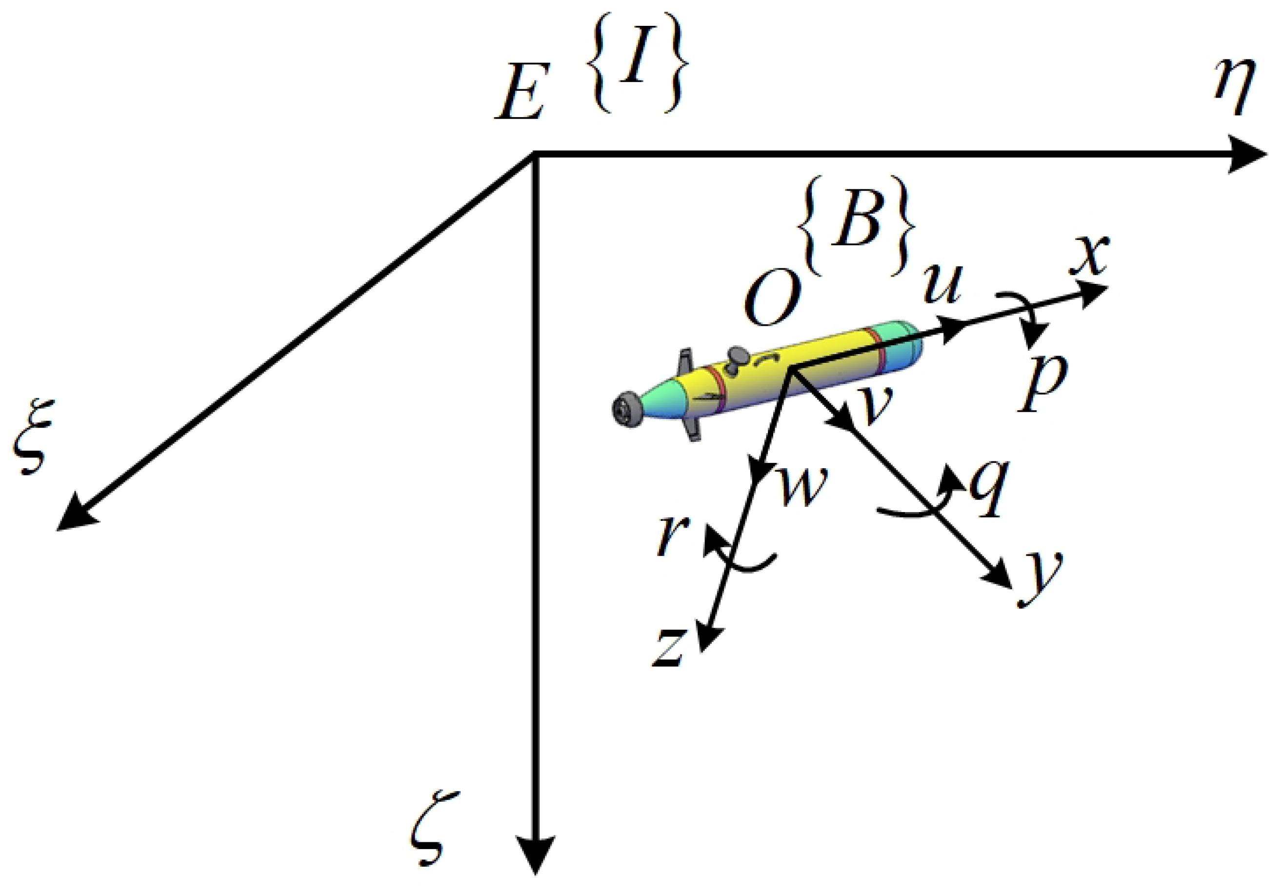
Figure 1. The coordinate system of AUV.
Jmse 13 01687 g001
Figure 2. The structure of controller.
Jmse 13 01687 g002
Figure 3. Schematic representation of performance constraints.
Jmse 13 01687 g003
Figure 4. The trajectory of AUV.
Jmse 13 01687 g004
Figure 5. (a) The ξ η view of position. (b) The ξ ζ view of position.
Jmse 13 01687 g005
Figure 6. The response of position.
Jmse 13 01687 g006
Figure 7. The response of attitude.
Jmse 13 01687 g007
Figure 8. The response of position error.
Jmse 13 01687 g008
Figure 9. The response of attitude error.
Jmse 13 01687 g009
Figure 10. The response of position error derivatives.
Jmse 13 01687 g010
Figure 11. The response of attitude error derivatives.
Jmse 13 01687 g011
Figure 12. The response of velocity.
Jmse 13 01687 g012
Figure 13. The response of angular velocity.
Jmse 13 01687 g013
Figure 14. The response of force.
Jmse 13 01687 g014
Figure 15. The response of torque.
Jmse 13 01687 g015
Figure 16. Comparison of maximum values of force and torque.
Jmse 13 01687 g016
Figure 17. (a) The response of ADP weights. (b) The response of OSM-ADP weights.
Jmse 13 01687 g017
Figure 18. The response of the value function.
Jmse 13 01687 g018
Figure 19. (a) The response of S 1 S 3 . (b) The response of S 4 S 5 .
Jmse 13 01687 g019
Table 1. Model parameters of AUV-S.
m S = 185 kg B S = W S = 1813 N B G ¯ S = 0.02 m
m 11 S = 215 kg X u S = 70 kg / s X u | u | s = 100 kg / m
m 22 S = 265 kg Y v S = 100 kg / s Y v | v | S = 200 kg / m
m 33 S = 265 kg Z w S = 100 kg / s Z w | w | S = 200 kg / m
m 44 S = 80 kg · m 2 M q S = 50 kg · m 2 / s M q | q | S = 100 kg · m 2
m 55 S = 80 kg · m 2 N r S = 50 kg · m 2 / s N r | r | S = 100 kg · m 2
Table 2. Model parameters of AUV-M.
m M = 30.5 kg B M = W M = 299 N B G ¯ M = 0.01987 m
m 11 M = 31.43 kg X u M = 1.35 kg / s X u | u | M = 1.62 kg / m
m 22 M = 66 kg Y v M = 66.6 kg / s Y v | v | M = 131 kg / m
m 33 M = 66 kg Z w M = 66.6 kg / s Z w | w | M = 131 kg / m
m 44 M = 8.33 kg · m 2 M q M = 6.87 kg · m 2 / s M q | q | M = 9.4 kg · m 2
m 55 M = 8.33 kg · m 2 N r M = 6.87 kg · m 2 / s N r | r | M = 9.4 kg · m 2
Table 3. Comparison of initial and final values of value functions.
MethodsInitial ValueFinal Values
ADP3120.043
OSM-ADP18.90.041
Disclaimer/Publisher’s Note: The statements, opinions and data contained in all publications are solely those of the individual author(s) and contributor(s) and not of MDPI and/or the editor(s). MDPI and/or the editor(s) disclaim responsibility for any injury to people or property resulting from any ideas, methods, instructions or products referred to in the content.