Article

Design of Organic Rankine Cycle Recovering Multi-Grade Waste Heat from a Two-Stroke Marine Engine

1
School of Nuclear Science, Energy and Power Engineering, Shandong University, Jinan 250061, China
2
Weichai Power Co., Ltd., Weifang 261061, China
3
Shenzhen Research Institute of Shandong University, Shenzhen 518057, China
4
Department of Mechanical Engineering, University of Bath, Bath BA2 7AY, UK
*
Authors to whom correspondence should be addressed.
J. Mar. Sci. Eng. 2025, 13(9), 1679; https://doi.org/10.3390/jmse13091679
Submission received: 29 July 2025 / Revised: 27 August 2025 / Accepted: 27 August 2025 / Published: 1 September 2025
(This article belongs to the Section Ocean Engineering)

Abstract

Waste heat recovery using Organic Rankine Cycle (ORC) systems shows significant potential for reducing CO2 emissions from ships. This study designs and analyzes ORC systems for recovering multi-grade waste heat from the exhaust gas, jacket water, and scavenging air of a marine two-stroke diesel engine. A thermodynamic model is developed to investigate the effects of working fluid preheating temperature, evaporation pressure, and heat source conditions on system performance. Results show that appropriately increasing the preheating temperature of the working fluid can enhance power output. For hydrocarbons with higher critical temperatures, power output exhibits an extremum as preheating temperature increases, while for fluids with lower critical temperatures, power output increases continuously until the evaporation pressure limit is reached. Increasing evaporation pressure decreases power output but improves thermal efficiency, with a corresponding increase in heat transfer and exergy loss rates in the exhaust gas preheater. Additionally, the temperature of the heat source has an important effect on the energy and exergy balance distribution and power output of the ORC. For every 10 K rise in exhaust temperature, the bottoming cycle power output of cyclohexane increases by approximately 12.3%. This study provides theoretical support for efficient marine waste heat recovery and working fluid selection.

1. Introduction

With the development of international trade, CO2 emissions from the shipping sector have been gradually increasing. According to the Fourth Greenhouse Gas Study by the International Maritime Organization (IMO), the share of CO2 emissions from shipping in total global CO2 emissions rose from 2.76% in 2012 to 2.89% in 2018 [1]. To curb the growth of CO2 emissions in the maritime sector, the IMO has mandated a 5% reduction in carbon emissions starting in 2023, relative to 2019 levels, followed by an annual reduction of 2% thereafter [2]. To achieve these targets, a variety of technologies have been proposed to enhance ship operational efficiency, including weather routing, slow steaming, air lubrication, propeller polishing, waste heat recovery, and hull coating [3,4]. Among these, waste heat recovery is regarded as a key technology capable of significantly improving operational efficiency and reducing CO2 emissions.
As the primary equipment for fuel energy conversion on ships, marine diesel engines, particularly two-stroke engines, are designed to achieve high thermal efficiency (approximately 50%), which approaches the theoretical maximum efficiency of an ideal cycle under current engine strength and emission constraints [5]. However, approximately 50% of the total energy from fuel combustion in marine diesel engines is lost to the environment via exhaust gas, jacket cooling water, and scavenging air, making waste heat recovery (WHR) systems a prominent area of research [6]. Typical WHR technologies commonly adopted in marine applications include thermoelectric generation (TEG), turbo-compounding, and bottoming cycles. The TEG system, while compact and silent, typically exhibits a modest conversion efficiency of 3–5%, and its broader deployment hinges on the development of thermoelectric materials that are cost-effective, efficient, and robust [7,8]. Turbo-compounding has emerged as a cost-efficient solution in marine diesel engines, offering improved fuel utilization without compromising on size or design simplicity [9]. Among bottoming cycles, both organic Rankine cycle (ORC) and steam Rankine cycle (SRC) technologies have been successfully demonstrated in practical shipboard applications by major engine manufacturers [10,11].
The SRC system is a mature solution that has been extensively studied in the context of maritime propulsion systems [12]. A dual-pressure SRC system, as implemented by MAN [6], has been shown to reduce fuel consumption by approximately 9–11%, with the low-pressure steam stream utilized for preheating the organic working fluid. However, studies by Ringler et al. [13] and Sprouse and Dapcik [14] have indicated that RC systems generally outperform ORCs only when the heat source exceeds 300 °C or even 370 °C. As a result, increasing attention has shifted towards optimizing ORC design and selecting suitable working fluids. Unlike SRC systems, which rely on water, the ORC enables recovery from low- and medium-grade thermal sources due to the wide range of applicable working fluids. However, working fluids serve as the medium for converting thermal energy into work and thus have a direct impact on cycle performance. Gürgen et al. [15] conducted a comprehensive evaluation of ten working fluids in a regenerative ORC installed on a 2200 TEU LNG-powered container ship equipped with a dual-fuel engine. They reported that R245fa achieved a net output power of 439.58 kW and an electricity production cost of 0.0569 USD/kWh. Li et al. [16] assessed the thermoeconomic performance of R1234yf, R134a, R245fa, R600, R245ca, and R600a on a MAN B&W 6S35ME-B9 two-stroke marine diesel engine, finding that R245ca delivered the best overall performance, with a net output of 354.19 kW and a cost of 0.115 USD/kWh. R1233zd(E), R1234ze(Z), and R1243ye(E) exhibit negligible ozone-depletion potential (ODP), low global warming potential (GWP), and critical parameters comparable to those of R245ca and R245fa, making them promising candidates for onboard waste heat recovery [17,18]. Comparative studies [19] have demonstrated that n-butane, isobutane, isopentane, cyclopentane, and cyclohexane offer favorable thermodynamic properties. Moreover, when the heat-source temperature is raised to 380 °C, alkylbenzenes such as benzene and toluene exhibit increasing thermal efficiency and thus emerge as attractive working fluids. For flue gas waste heat recovery at a 380 °C inlet, Fernández et al. [20] evaluated six siloxane fluids (D4, D5, D6, MM, MDM, and MD2M), finding that systems using MM or MDM achieved the highest thermal efficiencies alongside excellent fluid thermal stability. Larsen et al. [21] explored the impact of regenerative ORC systems utilizing different working fluids on the fuel efficiency of a 68.52 MW marine diesel engine. Their numerical analysis revealed that employing isohexane as the working medium can achieve a 6% reduction in fuel consumption. Similarly, Akman and Ergin [22] conducted a performance assessment under off-design conditions for different ORC systems. Their simulation results, based on a MAN 12K98 engine model, demonstrated that the use of R245fa could enhance thermal efficiency by 6.7%.
The structural design of the ORC system should take into account the quality and distribution of the recoverable waste heat sources from the engine. The ORC system can be implemented in various layouts, including basic, regenerative, and dual-loop schemes [23]. According to Yang and Yeh [24], regenerative configurations utilizing exhaust gas can enhance output by up to 10% relative to basic systems. Grljušić et al. [25] developed a simplified ORC layout that simultaneously utilizes waste heat from exhaust gas, scavenging air, and jacket cooling water. In another study, Song et al. [26] demonstrated that a dual-loop ORC architecture, using exhaust gas and cylinder jacket water as heat sources, could yield an 11.6% boost in net power compared to the baseline engine output. Mondejar et al. [27] conducted a study on integrating a basic ORC system into an existing cruise ship to recover waste heat from both main and auxiliary engine exhaust gases. The results demonstrated that an ORC system using benzene with internal regeneration could supply up to 22% of the ship’s total electricity consumption. Yuksek et al. [28] developed a modular, high-efficiency ORC system designed to recover low-grade heat from the jacket water of large marine engines. The results demonstrated that integrating the ORC unit into the engine cooling systems of vessels can produce up to 125 kW of electric power. Song et al. [29] proposed a dual-source basic ORC system that recovers waste heat from both the jacket cooling water and engine exhaust gas of a marine diesel engine. The results indicated that the maximum net power output of the optimized system using cyclohexane as the working fluid reaches 99.7 kW, only 1.4% lower than that of the two separated systems. Tayyeban et al. [30] investigated a basic ORC system coupled with a natural gas engine, using exhaust gas and cylinder jacket water as heat sources. Their study optimized the thermodynamic and geometric parameters of a piston-type expander, identifying R134a as the most effective working fluid for enhancing energy recovery and reducing emissions. Zhang et al. [31] proposed an ORC configuration design method that uses the all-condition energy matching degree between the cycle and its multiple waste heat sources as an evaluation index. The results showed that engine coolant is the most specific waste heat source and highlighted the difficulty of achieving high energy matching when coolant is recovered simultaneously with exhaust or charge air.
Despite the extensive research on ORC applications for single-source waste heat recovery, existing studies have largely focused on either exhaust gas or jacket cooling water in isolation, while overlooking the potential of multi-grade heat sources. Moreover, systematic investigations on the synergistic utilization of these heat sources under varying operating conditions remain limited. In particular, the effects of key thermodynamic parameters, such as working fluid preheating temperature, evaporation pressure, and heat source temperature, on the energy and exergy performance of ORC systems using different types of working fluids have not been comprehensively explored. The selection of working fluids is also often constrained to a narrow range of substances, without fully considering the influence of critical temperature characteristics on system behavior across multi-grade heat sources.
In this paper, an ORC system is designed and modeled for the large temperature gradient waste heat of the exhaust gas, the jacket water, and the scavenging air of a two-stroke marine diesel engine. Seven working fluids, benzene, hexane, isohexane, cyclohexane, pentane, R245ca, and R1233zd(E), are used as the objects of study, and the effects of preheating temperature, evaporation pressure, and heat source working conditions on the performance of the ORC system were investigated through energy and exergy analysis.

2. System Description

In this section, the selection of working fluids and the configuration design for an ORC system recovering multi-grade waste heat from exhaust gas, cooling water, and scavenging air are first presented. Subsequently, the thermodynamic model of the ORC waste heat recovery system is developed.

2.1. ORC System

The configuration and heat transfer matching diagram of the ORC system is presented in Figure 1. The organic working fluid is pressurized by a pump and first passes through the jacket water preheater (JW_PRE) and the scavenging air preheater (SA_PRE), where it is preheated to a higher temperature. It then enters the exhaust gas heat exchanger, where it is further heated by the exhaust gas preheater (EG_PRE) to reach a saturated liquid state, followed by complete vaporization in the exhaust gas evaporator (EG_EVA) to form saturated vapor. The high-temperature, high-pressure vapor enters the expander to produce mechanical work. After expansion, the working fluid flows into the condenser, where it is condensed into a saturated or subcooled liquid.
Compared to the conventional steam Rankine cycle, the ORC can achieve higher thermal efficiency in low- and medium-temperature waste heat recovery applications by employing organic working fluids with lower boiling points. Since the choice of working fluid directly affects cycle efficiency and component design, appropriate fluid selection is a critical aspect in ORC system development. Wet working fluids are prone to entering the two-phase region at the expander outlet, where the formation of liquid droplets may cause blade erosion and compromise turbine stability [32]. Therefore, dry and isentropic fluids are preferable candidates. In addition, working fluids should exhibit favorable thermophysical properties and suitable evaporation and condensation pressures. Previous studies [33] have indicated that working fluids with high density, low specific heat capacity, high latent heat, and appropriate operating pressures contribute to improved power output and thermal efficiency. Safety and environmental considerations are also essential [34]. According to the Montreal Protocol, the use of hydrochlorofluorocarbon (HCFC) as working fluids will be phased out by 2030 [35].
Based on the aforementioned working fluid selection criteria and considering an exhaust temperature of up to 520 K, the critical temperature range of the candidate fluids is chosen to be 430–565 K. In this study, seven working fluids are selected: benzene, hexane, isohexane, cyclohexane, pentane, R245ca, and R1233zd(E). Among them, R245ca is a hydrofluorocarbon (HFC), R1233zd(E) is a hydrofluoroolefin (HFO), and the remaining fluids are hydrocarbons (HCs). The specific thermophysical properties of the selected fluids are listed in Table 1.

2.2. Thermodynamic Description

Neglecting kinetic and potential energies of the working fluid, the formulas for energy and exergy balances within the steady-state control volume can be described as follows [36]:
Q ˙ + W ˙ = m ˙ o u t h o u t m ˙ i n h i n
I ˙ c v = E ˙ X , i n E ˙ X , o u t W ˙ + 1 T 0 T   Q ˙
in which I c v represents the irreversibility derived from the exergy balance over the entire control volume under steady-state conditions, subscripts ‘in’ and ‘out’ indicate the inlet and outlet parameters of a control volume, and ‘h’ represents the specific enthalpy of the working fluid. Further, the exergy flow rate ‘Ex’ flowing into or out of the control volume can be expressed as follows:
E ˙ X = m ˙ h h 0 T 0 s s
in which subscript ‘0’ represents the ambient condition, and ‘s’ indicates the specific entropy. In the following, the energy balance and exergy balance description of the components of the ORC will be given according to Equations (1)–(3).
(1)
Evaporator:
The heat transfer rate in the evaporator is depicted as follows:
Q ˙ e v a = m ˙ w f h w f , o u t h w f , i n = m ˙ h s h h s , i n h h s , o u t
The local exergy destruction rate within the evaporator is as follows:
I ˙ e v a = T 0 m ˙ w f s w f , o u t s w f , i n + m ˙ h s s h s , o u t s h s , i n
in which m ˙ w f is the mass flow rate of the working fluid and m ˙ h s is the mass flow rate of the heat source. The overall heat transfer capability of the evaporator is characterized by the UA value, which represents the product of the overall heat transfer coefficient (U) and the effective heat transfer area (A). Instead of specifying U and A separately, this generalized approach enables the evaluation of heat transfer performance at the system level. Accordingly, the heat transfer rate through the evaporator can be expressed as follows:
Q ˙ = U A T l m
in which ∆Tlm is the log-mean temperature difference. For the countercurrent shell and tube evaporator, it can be expressed as follows:
Δ T l m = T g , i n T w , o u t T g , o u t T w , i n l n T g , i n T w , o u t / T g , o u t T w , i n
in which subscripts ‘g’ and ‘w’ refer to the state parameters of the gas and water sides of the evaporator, respectively.
In the system, the UA value required per unit of net power output, i.e., the UPR value, is used to express the heat transfer performance of the evaporator. Therefore, the UPR value can be expressed as follows [37]:
U P R = U A W ˙ O R C
(2)
Expander:
The power output from the expander is described as follows:
W ˙ e x p = m ˙ w f h e x p , i n h e x p , o u t
The exergy loss flow in the expander is as follows:
I ˙ e x p = m ˙ w f T 0 s e x p , o u t s e x p , i n
(3)
Condenser:
The heat release rate of the working fluid in the condenser is calculated by the following:
Q ˙ c o n d = m ˙ w f h c o n d , i n h c o n d , o u t
The exergy loss flow in the condenser is as follows:
I ˙ c o n d = m ˙ w f T 0 s c o n d , o u t s c o n d , i n + Q ˙ c o n d
(4)
Pump:
The power consumed by the pump is as follows:
W ˙ p = m ˙ w f h p , o u t h p , i n
The exergy loss flow in the pump is as follows:
I ˙ p = m ˙ w f T 0 s p , o u t s p , i n
It should be noted that the above calculations assume that the available energy carried away by the cooling water is not recovered. Taking into account the gear transmission and generator efficiency, the net power output and thermal efficiency of the ORC can be expressed as follows:
W ˙ O R C = η g e a r η g e n W ˙ e x p W ˙ p
η O R C = W ˙ O R C m ˙ s a h s a , i n h s a , o u t + m ˙ j w h j w , i n h j w , o u t + m ˙ e g h e g , i n h e g , o u t
in which subscript ‘gear’ indicates the gearbox, ‘gen’ represents the generator, ‘sa’, ‘jw’, and ‘eg’ indicate the scavenging air, jacket water, and exhaust gas, respectively.

3. Model Building and Validation

3.1. Model Building

A marine two-stroke diesel engine (6EX340) was selected as the base engine in this work, and its main specifications are provided in Table 2. This engine is widely used in river–sea combined transport and short-sea shipping, such as handy-size oil tankers and feeder container ships. In the authors’ previous work [38], a sophisticated thermodynamic model of the topping in-cylinder Diesel cycle was developed and validated using this engine. Building on the validated diesel engine model, this section focuses on the modeling of the ORC system. The ORC system is designed for the 100% engine load condition to ensure safe operation under maximum thermal demand. This approach guarantees sufficient component sizing and prevents overheating or under-expansion under full-load navigation conditions. At 100% engine load, the exhaust gas flow rate reaches 11.3 kg/s with a temperature of 520.1 K, measured downstream of the turbocharging system. The jacket water outlet temperature is maintained at 363 K, and the inlet temperature is regulated to 343 K to ensure thermal stability and maximize heat flow recovery. The inlet and outlet temperatures of the scavenge air are 480.8 K and 316.8 K, respectively. Meanwhile, the mass flow rates of the jacket cooling water and scavenge air are 9.0 kg/s and 11.1 kg/s, respectively.
Table 3 lists the key design parameters and constraints for each component of the ORC system. The pinch point temperature difference refers to the minimum temperature difference between the hot and cold fluids in a heat exchanger and is a critical factor in determining heat transfer efficiency. A smaller pinch point temperature difference generally indicates higher heat transfer efficiency; however, excessively small values may lead to impractically large heat exchanger sizes. Considering both steam generation and heat exchanger dimensions, the pinch point temperature difference inside the evaporator is set to 20 °C. To prevent sulfuric acid corrosion, the exhaust gas temperature after passing through the evaporator is required to remain above 145 °C. Given the low density ratio and specific enthalpy difference in the organic working fluid, the turbine efficiency is set at 72% [39]. Additionally, it is assumed that the cooling water can preheat the working fluid to 80 °C under various operating conditions.
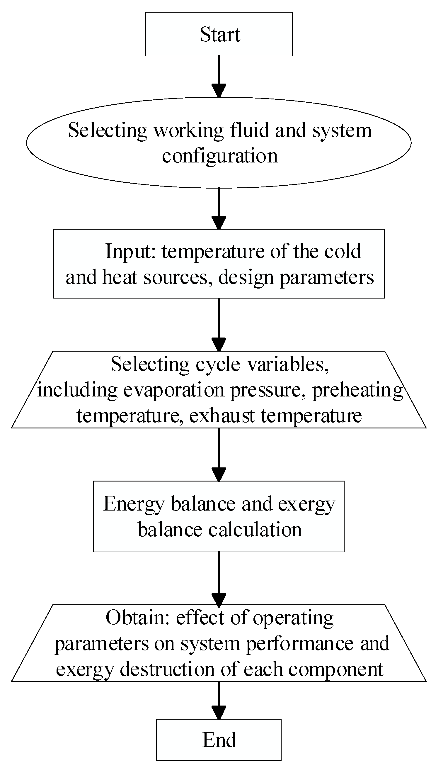
Neglecting internal pressure losses and external heat flow losses in each component, and combining the energy and exergy balance equations, the calculation flow of the ORC system is illustrated in Figure 2. MATLAB R2023a was used to implement the entire ORC calculation process, while REFPROP, developed by NIST, was employed to obtain thermophysical properties of the working fluid and heat source at each state point. First, the working fluid and design parameters are selected. Then, variations in evaporation pressure, preheating temperature, and heat source conditions are analyzed to evaluate system performance and determine the optimal thermodynamic state parameters.

3.2. Model Validation

The ORC model used in this study is adapted from the Rankine cycle model developed in the authors’ previous work [10]. The model results were validated by comparison with the published data of Andreasen et al. [39]. Under identical system configurations and operating conditions, the predicted values of high-pressure steam mass flow rate, net output work, and total UA were all in good agreement with the reference data, with a maximum deviation of less than 5%. Detailed validation results are available in the authors’ earlier publication. Therefore, the model developed in this study is considered sufficiently accurate for subsequent simulations and analyses.

4. Results and Discussion

This section examines the influences of working fluid preheating temperature, evaporation pressure, and heat source conditions on the performance of the waste heat recovery bottoming cycle system.

4.1. Effects of Preheating Temperature

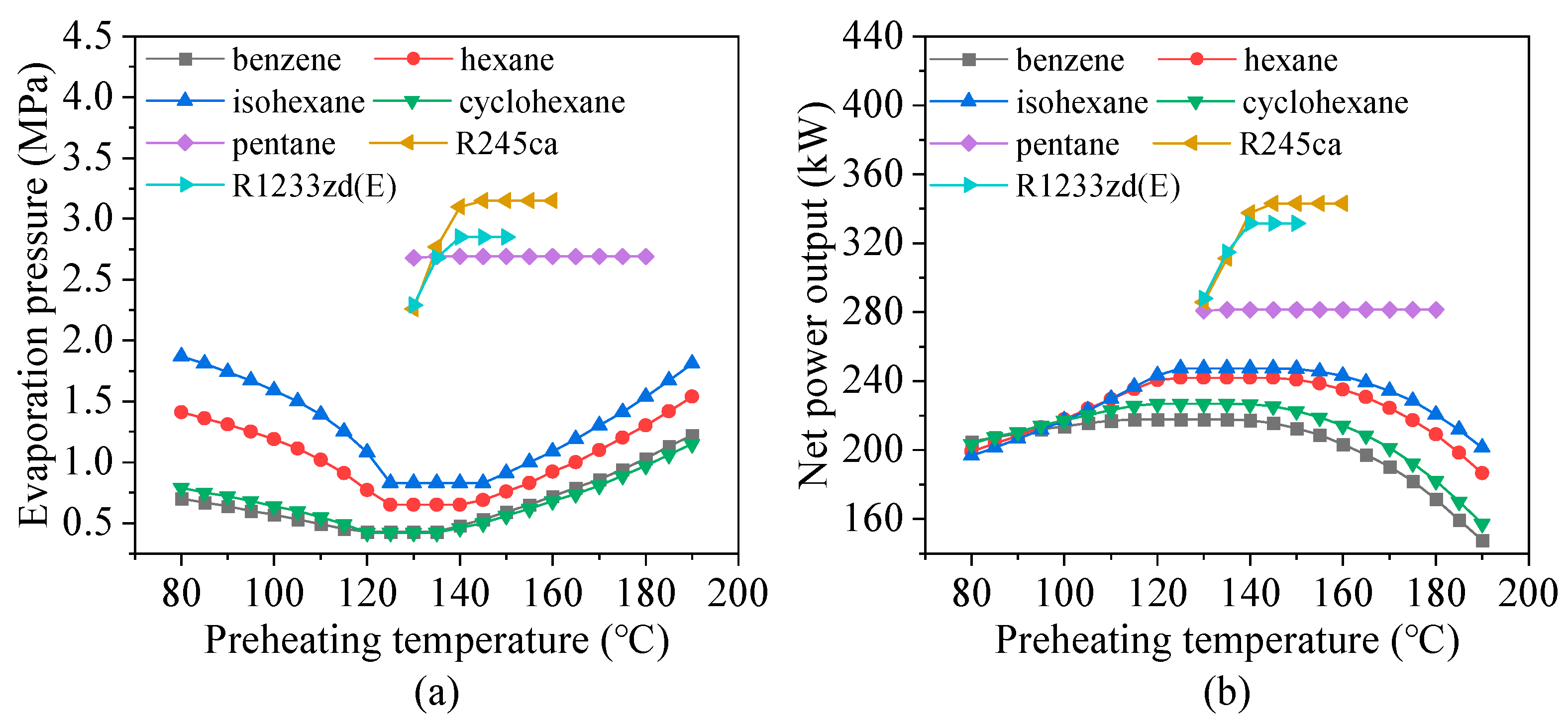
The preheating temperature refers to the temperature of the working fluid exiting the scavenging air heat exchanger. Due to the varying exergy levels of the scavenging air under different conditions, the preheating temperature of the working fluid exhibits significant fluctuations. To maximize the net power output, the performance parameters of the ORC were evaluated at different preheating temperatures. Considering that the critical temperatures of pentane, R245ca, and R1233zd(E) are lower than that of the heat source (247 °C), and accounting for the constraints imposed by the minimum exhaust gas outlet temperature (145 °C) and the maximum allowable evaporation pressure ( 0.8 · P c r i t ), the applicability of these three fluids is limited in the preheating temperature analysis. Figure 3 illustrates the effect of preheating temperature on the optimal evaporation pressure and net power output of the ORC. For benzene, hexane, isohexane, and cyclohexane, the net power output first increases and then decreases with increasing preheating temperature, with respective peak values occurring at approximately 135 °C, 140 °C, 145 °C, and 135 °C, respectively. In contrast, for R245ca and R1233zd(E), the net power output increases continuously with preheating temperature, reaching maximum values of 343 kW and 332 kW when the preheating temperature exceeds 140 °C. For pentane, the net power output remains nearly constant. This is attributed to its relatively low critical temperature and pressure, which result in the optimal evaporation pressure consistently reaching its upper limit across all preheating temperatures. Since the inlet temperature of the heat source remains unchanged, variations in the preheating temperature have a negligible impact on the mass flow rate, evaporation temperature, and thermal efficiency of the ORC system using pentane.
Figure 4 illustrates the effect of preheating temperature on the thermal efficiency of the ORC system. Thermal efficiency initially decreases and then increases with rising preheating temperature. As shown in Figure 3, although thermal efficiency and net power output exhibit opposite trends for various working fluids, the selection criterion in this study prioritizes maximum net power output. This is because the heat source originates from the waste heat of a marine diesel engine operating under full-load conditions. Since this waste heat is continuously available and does not incur additional fuel cost, maximizing recovered work is more beneficial for marine applications. As the preheating temperature rises to approximately 130 °C, the heat transfer rate reaches its maximum, while the thermal efficiency attains its minimum. With further increases in preheating temperature, the heat flow transferred from the exhaust gas in the evaporator decreases significantly due to the constraint of the minimum exhaust gas outlet temperature (145 °C) and the pinch point temperature difference in the evaporator. This reduction in heat transfer rate leads to an increase in the ORC thermal efficiency. The thermal efficiency of both the R245ca and R1233zd(E) systems varies consistently with their net output power, primarily because the relatively low critical temperatures of these working fluids result in lower evaporation temperatures and higher mass flow rates. As the preheating temperature increases, this further enhances the power output of the ORC system.
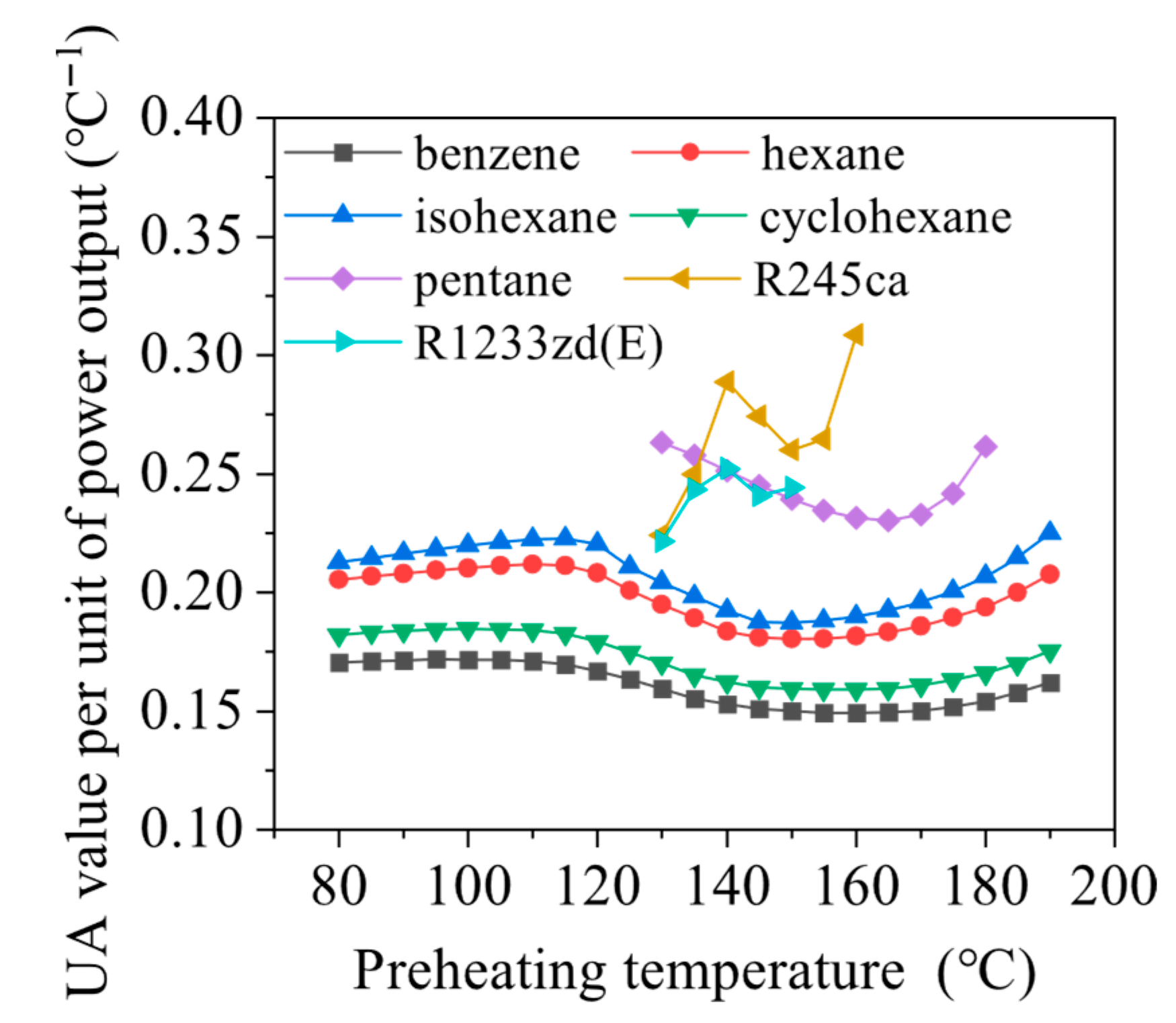
Figure 5 shows the effect of preheating temperature on the UPR value. It can be seen that there are two inflection points of the UPR curves for benzene, hexane, isohexane, and cyclohexane due to the higher critical temperatures. As shown in Figure 3a and Figure 5, the optimal evaporation pressure of the working fluids decreases with increasing preheating temperature. This reduction in pressure enhances the heat transfer capacity in the evaporator, thereby increasing both the UA value and the UPR of the system. When the preheating temperature reaches approximately 120 °C, the heat transfer rate in the evaporator peaks, and the UPR attains its maximum. Beyond this point, further increases in preheating temperature result in a reduction in the heat exchanged within the evaporator, while the specific net power output remains nearly constant. Consequently, the UPR begins to decline. When the preheating temperature exceeds 140 °C, the mass flow rate of the working fluid decreases significantly due to the constraints imposed by the minimum pinch point temperature difference in the evaporator. Under these conditions, the net power output decreases more sharply than the heat flow absorbed, leading to a minimum in the UPR.
The UPR curves of the ORC systems using R245ca and R1233zd(E) also exhibit two inflection points, although their underlying mechanisms differ from those of the four hydrocarbons discussed above. Unlike the aforementioned hydrocarbons, the lower critical temperatures of R245ca and R1233zd(E) lead to lower evaporation temperatures, which in turn result in higher mass flow rates over the range of preheating temperatures considered. As the preheating temperature increases, the optimal evaporation pressure gradually approaches its upper limit, leading to a maximum heat transfer rate in the exhaust boiler. Consequently, the UPR also reaches its maximum value. With the evaporation pressure held constant, the heat transferred in the exhaust heat exchanger decreases as the preheating temperature increases, leading to a minimum UPR value. Further increases in preheating temperature enhance heat transfer rate in the scavenging air heat exchanger (w2–w3), thereby increasing the UPR. Although the optimal evaporation pressure of pentane remains unaffected by the preheating temperature, the UPR first decreases and then increases as the preheating temperature rises. The underlying reason is that as the preheating temperature increases, the heat flow transferred to the working fluid in the exhaust gas preheater (w3–w4) decreases, while the heat transfer rate in the scavenging air heat exchanger increases. The combined effect of these two trends causes the total heat transfer rate in the system to first decrease and then increase with rising preheating temperature.
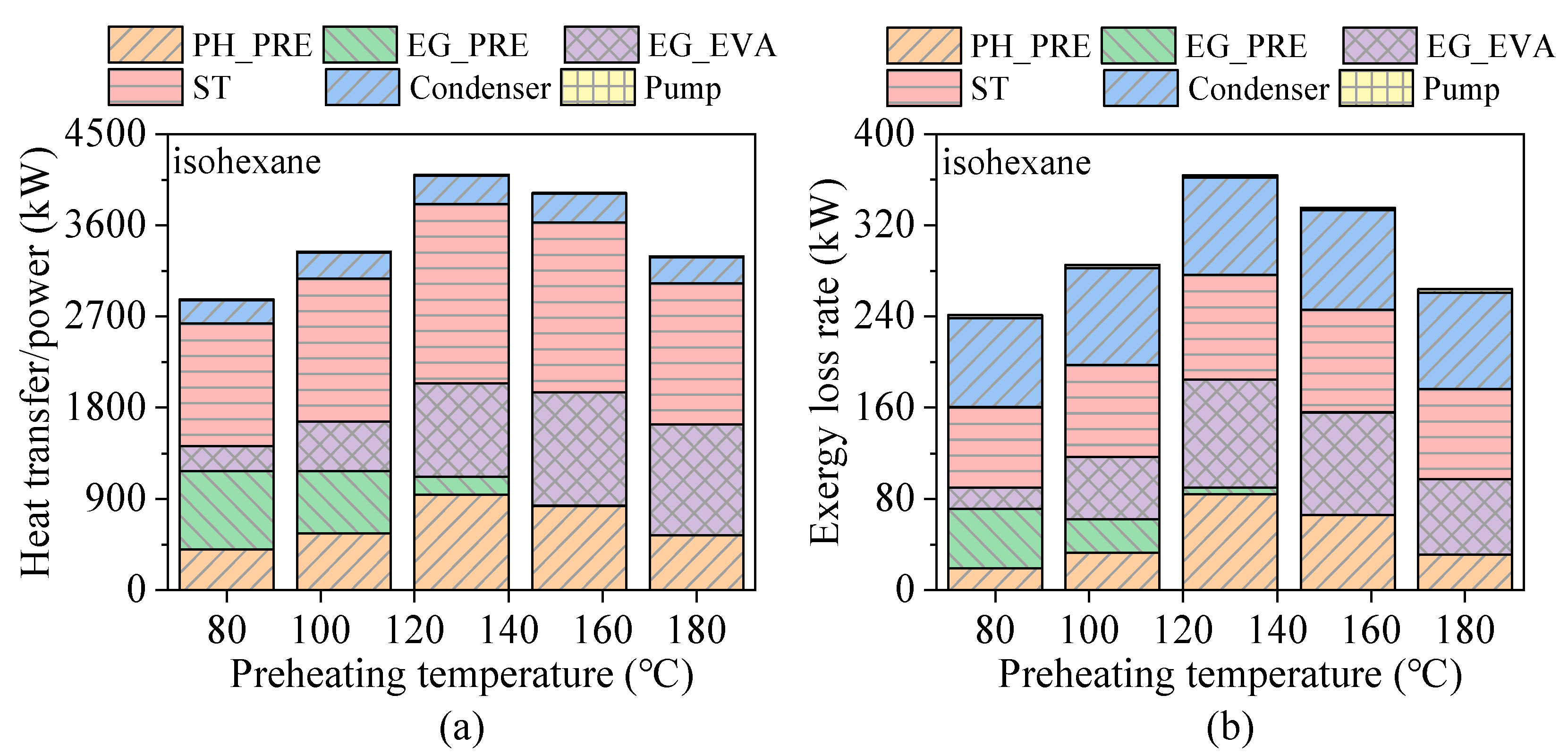
Although R1233zd(E) exhibits the highest net power output among the working fluids, its optimal performance is confined to a relatively narrow preheating temperature range of approximately 130–150 °C. In contrast, isohexane not only delivers relatively high net power output but also maintains stable performance across a broader preheating temperature range (80–180 °C), as shown in Figure 3b. Therefore, isohexane is selected for further analysis of thermal matching and exergy loss rate characteristics under varying preheating temperatures. Figure 6 presents the effect of preheating temperature on the exergy loss rate of each heat exchanger in the ORC system. At a preheating temperature of 80 °C, the system only recovers heat flow from the jacket water and exhaust gas. Under these conditions, the exhaust gas preheater exhibits the highest exergy loss rate, approximately 52 kW, while the evaporator and jacket water preheater show similar exergy loss rates of about 18.7 kW. This is primarily due to the large temperature difference across the exhaust gas preheater. As the preheating temperature increases to 145 °C, the exhaust gas is utilized exclusively in the evaporation section. The evaporator then shows the highest exergy loss rate of about 84.2 kW, followed by the scavenging air preheater at approximately 75.9 kW. At a preheating temperature of 180 °C, the scavenging air preheater surpasses the evaporator in exergy loss rate, reaching 54.9 kW. This value is about 27.7% lower than its exergy loss rate at 145 °C. This reduction is attributed to the decreased temperature difference across the scavenging air preheater, which simultaneously reduces the heat transfer rate in the evaporator.
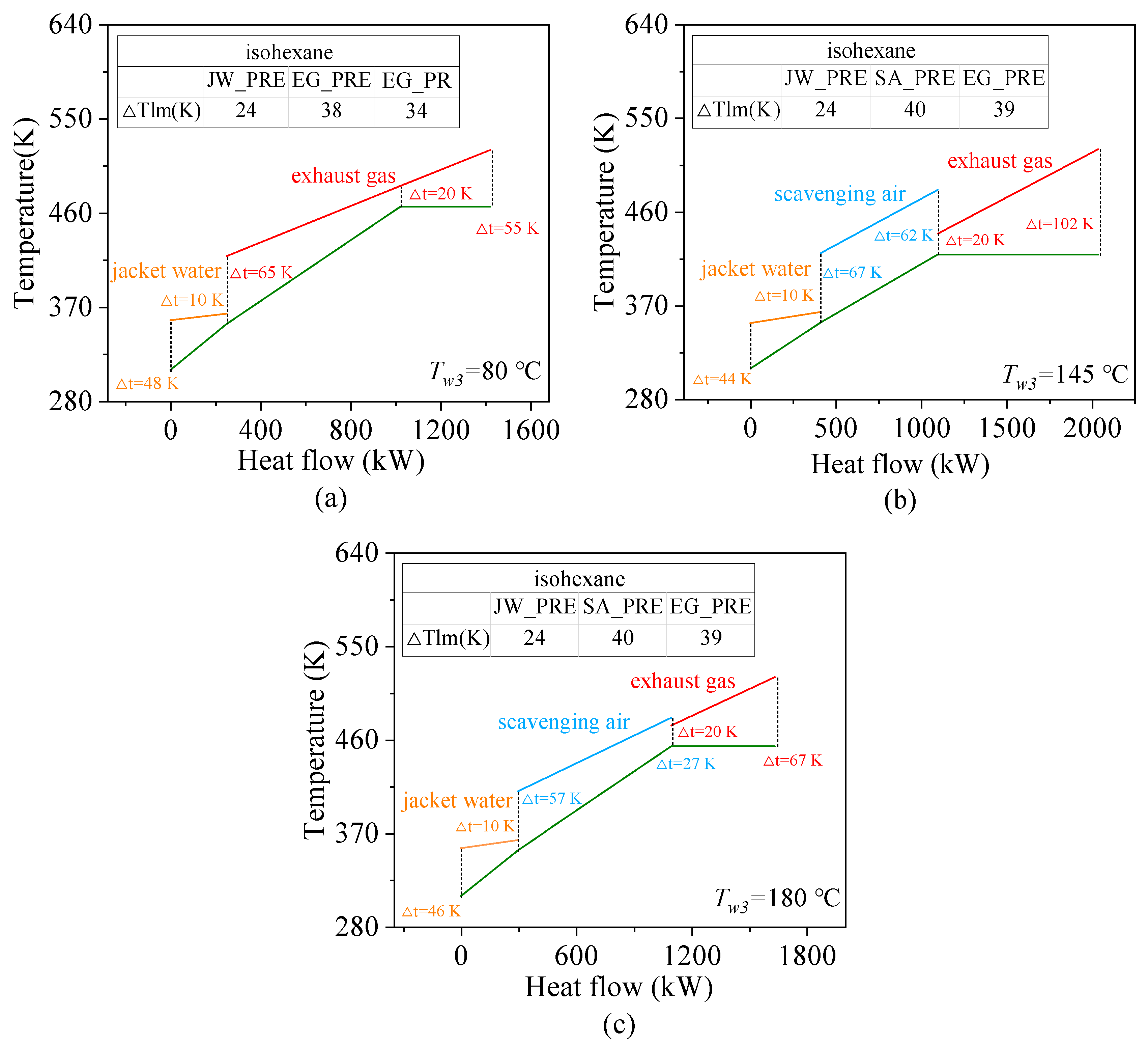
Figure 7 illustrates the effect of preheating temperature on the heat transfer matching characteristics of the ORC. The corresponding logarithmic mean temperature difference (∆Tlm) for each case is also presented. When the preheating temperature is 80 °C, the working fluid reaches a saturated liquid state in the exhaust gas preheater, recovering approximately 1176.5 kW of waste heat flow from the exhaust gas, accounting for 74.6% of the total recoverable exhaust heat flow. However, large temperature differences at both the inlet and outlet of the exhaust heat exchanger indicate poor thermal matching between the working fluid and the heat source. As the preheating temperature increases to 145 °C, the working fluid passes through the scavenging air preheater and reaches saturation. Under this condition, about 942.8 kW of waste heat flow is recovered from the exhaust gas and 687.4 kW from the scavenging air. When the preheating temperature is further increased to 180 °C, the amount of heat flow recovered from the scavenging air increases by about 16.5%, while the decrease in the exhaust gas temperature at the outlet of the evaporator reduces the amount of waste heat flow recovered from the exhaust gas. The proportion of exhaust gas waste heat flow recovery is about 34.4%, and the proportion of the total waste heat flow recovered in the ORC is reduced to 45%. In summary, increasing the working fluid temperature at the evaporator inlet can enhance the ORC’s power output. However, excessively high preheating temperatures result in a higher exhaust gas outlet temperature due to pinch point limitations in the evaporator, thereby significantly reducing the recoverable waste heat flow and degrading overall system performance.
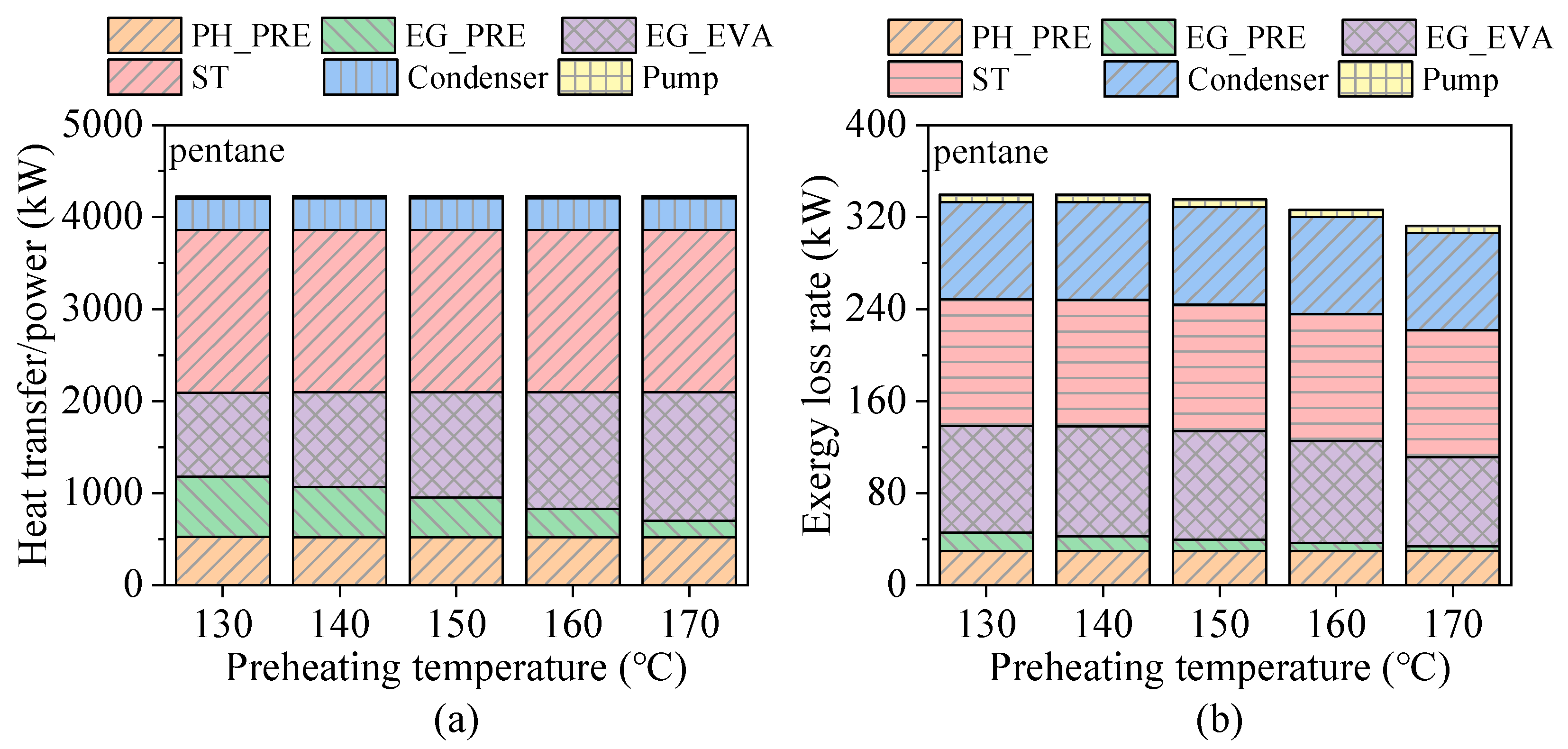
Since the preheating temperature of the jacket water is fixed at 80 °C, variations in thermodynamic parameters have no significant effect on the energy transfer or exergy loss rate in the jacket water heat exchanger. Therefore, the jacket water heat exchanger and the scavenging air heat exchanger are collectively considered as the preheating section. Considering that the performance curves of R245ca and R1233zd(E), as well as those of benzene, cyclohexane, hexane, and isohexane, exhibit similar trends with respect to preheating temperature, isohexane, pentane, and R1233zd(E) were selected for further analysis of the influence of preheating temperature on the system’s energy transfer and exergy destruction rates, as shown in Figure 8, Figure 9 and Figure 10. It can be observed that the trends in total energy input and total exergy loss rate closely follow the variation in the ORC net power output. As the preheating temperature increases, the energy transferred during the preheating process is gradually replaced by energy absorbed during the evaporation process. In terms of exergy loss rate distribution, as the preheating temperature increases, the exergy loss rate associated with the exhaust gas preheater for isohexane is similarly shifted toward the evaporator. For pentane, the distribution of exergy loss rate remains largely unaffected. In contrast, for R1233zd(E), the exergy loss rate in the preheating section is gradually transferred toward the exhaust gas heat exchanger.
For the ORC system, the working fluid preheating temperature corresponding to the maximum power output was selected for the subsequent analysis of other influencing parameters. Table 4 lists the preheating temperatures of the working fluid at the points of maximum system output. As shown in the table, the maximum output power for pentane, R245ca, and R1233zd(E) occurs at preheating temperatures of 180 °C, 160 °C, and 150 °C, which are close to the respective critical points of each fluid. Therefore, further investigations on the effects of evaporation pressure and heat source conditions cannot be conducted under these high-temperature conditions due to thermodynamic constraints near the critical point.

4.2. Effects of Evaporation Pressure

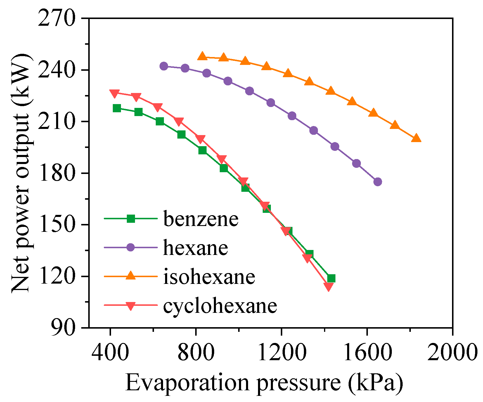
In the ORC system, the evaporation pressure significantly affects system performance. The effect of evaporation pressure on the net power output is presented in Figure 11. It can be observed that the power output of benzene, hexane, isohexane, and cyclohexane decreases with increasing evaporation pressure. This is because the selected preheating temperature limits the minimum allowable evaporation pressure, preventing the net power output curve from reaching its maximum point. Using isohexane (which yields the highest power output) as an example, Figure 12 illustrates the effects of evaporation pressure on the expander power output, pump power consumption, and working fluid mass flow rate. A comparison between Figure 11 and Figure 12 shows that the net power output of the ORC closely follows the trend of the expander power output, which is primarily governed by changes in the working fluid mass flow rate. In contrast, the relatively low power consumption of the pump has a negligible impact on the overall system performance.
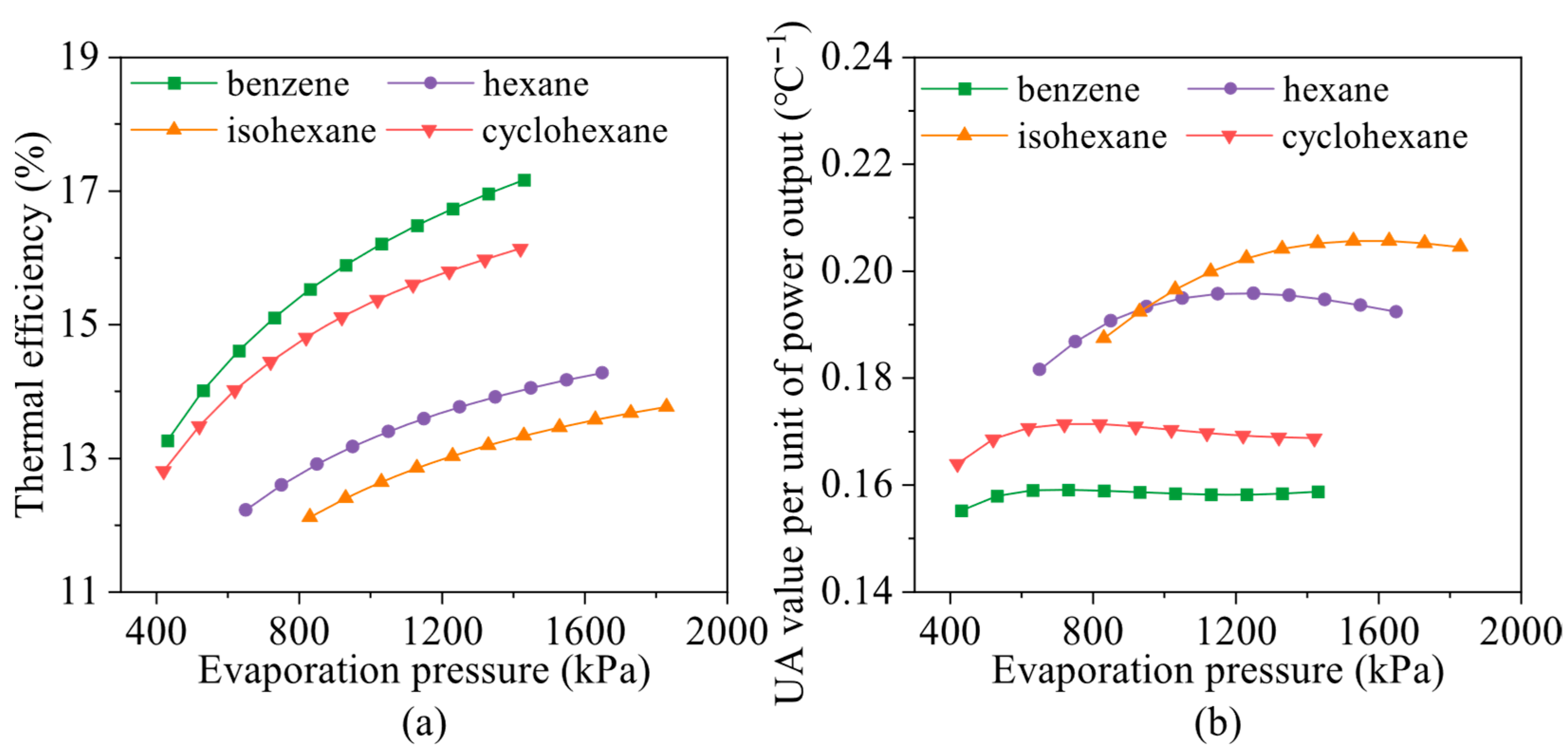
The effects of evaporation pressure on the thermal efficiency and UPR of the ORC are shown in Figure 13. As observed, the thermal efficiencies of benzene, hexane, isohexane, and cyclohexane increase gradually with increasing evaporation pressure, exhibiting an opposite trend to that of the net power output. This is primarily because higher evaporation pressure reduces the mass flow rate of the working fluid, leading to a substantial decrease in the system’s total heat transfer rate. Meanwhile, an increase in evaporation pressure enhances the heat transfer rate in the exhaust gas preheater while reducing it in the evaporator. These combined effects cause the UPR to first increase and then decrease as evaporation pressure continues to rise. Comparing Figure 11 and Figure 13b, it is evident that although isohexane yields a relatively high power output, its UPR value is also high, indicating a correspondingly large overall heat transfer coefficient (UA value) in the ORC system. As shown in Figure 11 and Figure 13, although isohexane presents lower thermal efficiency compared to some other fluids such as hexane, it delivers the highest net power output. Given the marine waste heat flow recovery context, where the heat flow input is not a limiting factor, net power output is considered the primary evaluation criterion. Therefore, isohexane is selected as the optimal working fluid under the operating conditions.
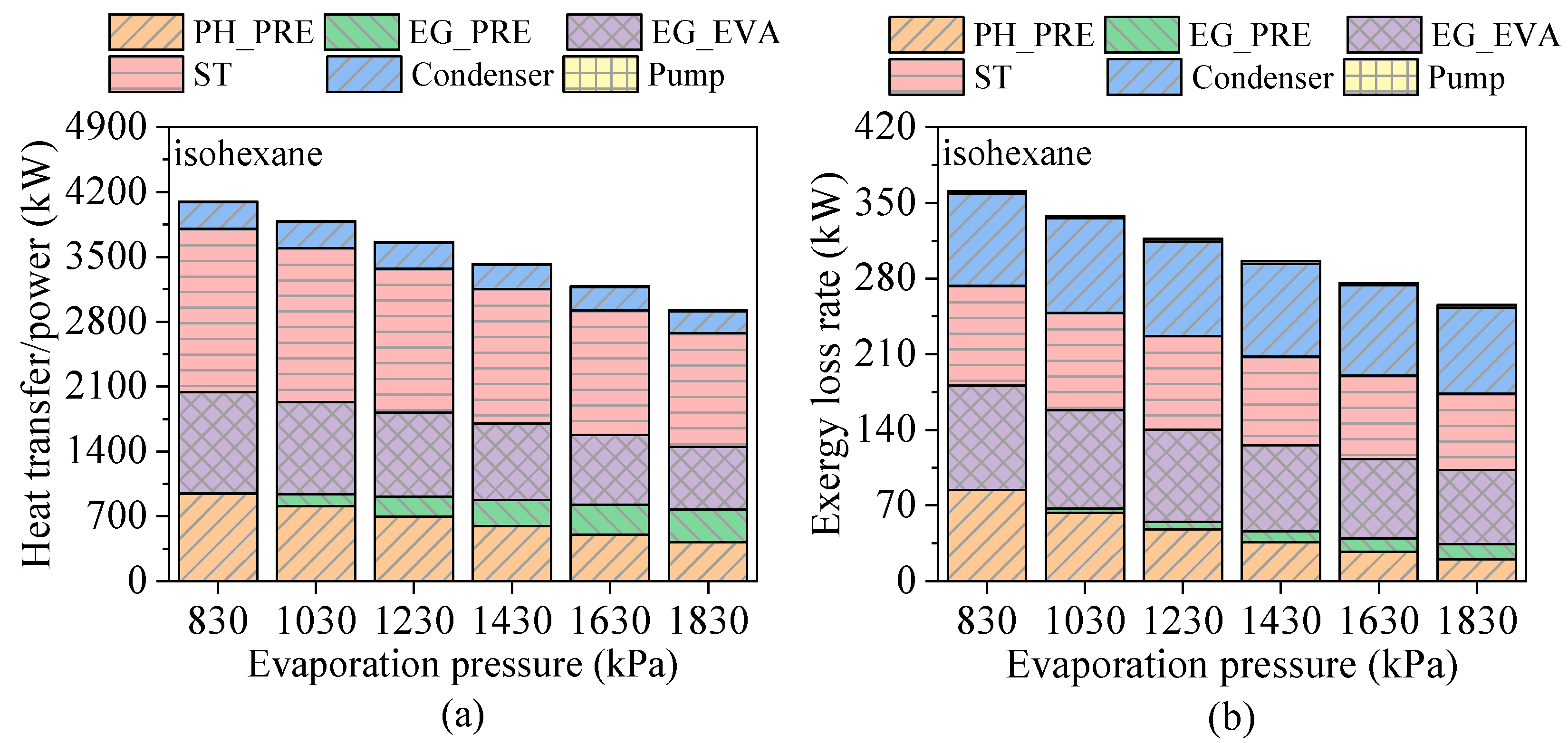
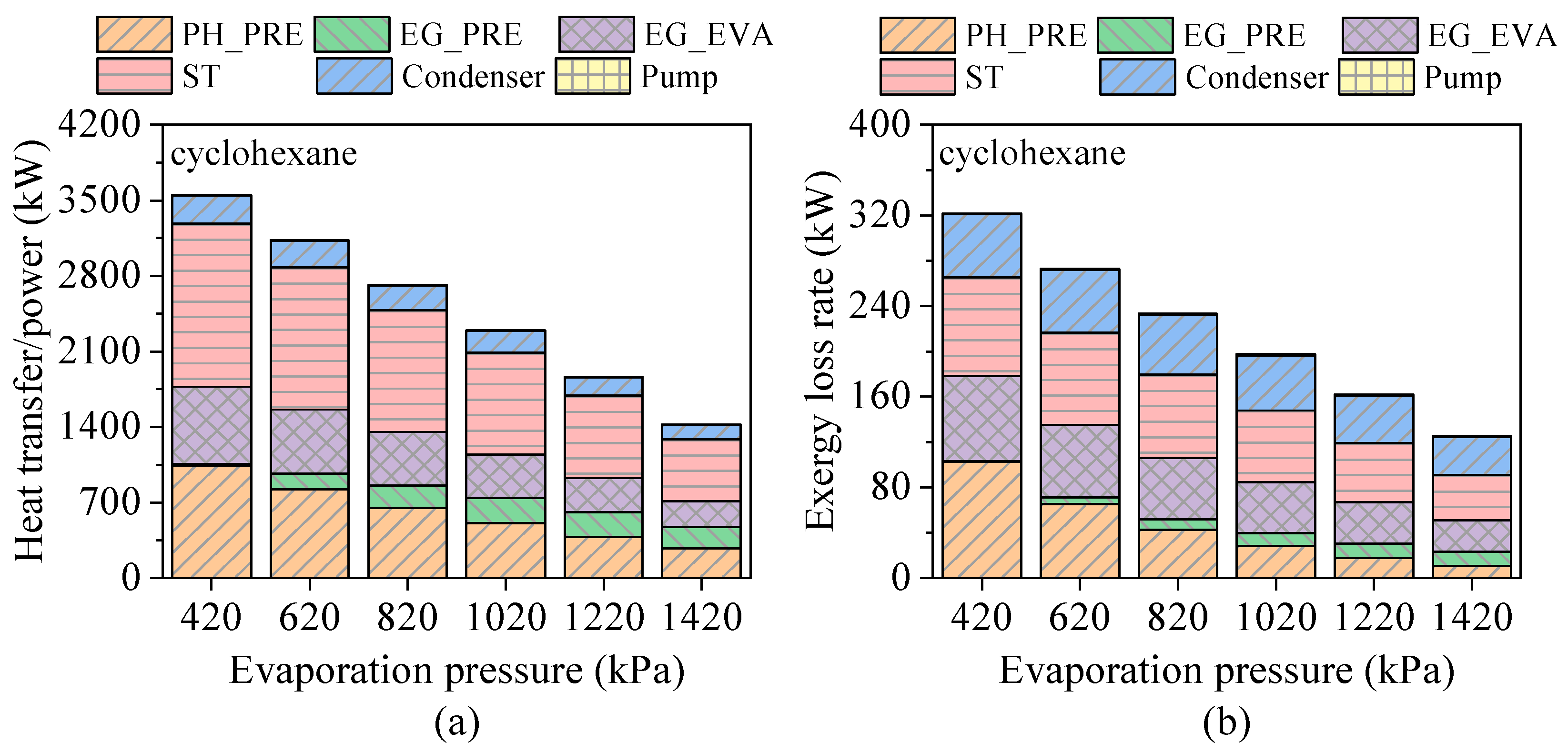
Considering that the performance curves of the benzene/cyclohexane and hexane/isohexane systems exhibit similar trends, isohexane and cyclohexane were selected to investigate the effects of evaporation pressure on the energy transfer and exergy destruction rates. As shown in Figure 14 and Figure 15, with increasing evaporation pressure, both the heat transfer rate and exergy loss flow in the preheating section are gradually shifted toward the exhaust gas preheater, leading to a higher heat transfer rate and exergy loss flow in that component. When isohexane is used as the working fluid, the heat transfer rate in the evaporator accounts for 53.6% of the total energy flow input, followed by the preheaters in the preheating and exhaust sections. In contrast, due to the higher critical temperature and pressure of cyclohexane, the largest portion of heat exchange occurs in the preheating section of the bottoming cycle, accounting for 58.9% of the total energy flow input. Furthermore, owing to the lower isentropic efficiency of the expander and the smaller pinch point temperature difference in the evaporator, the exergy loss rate during the expansion process slightly exceeds that associated with the heat transfer rate in the evaporator. The power consumption and exergy loss rate of the pump are negligible.

4.3. Effects of Heat Source Conditions

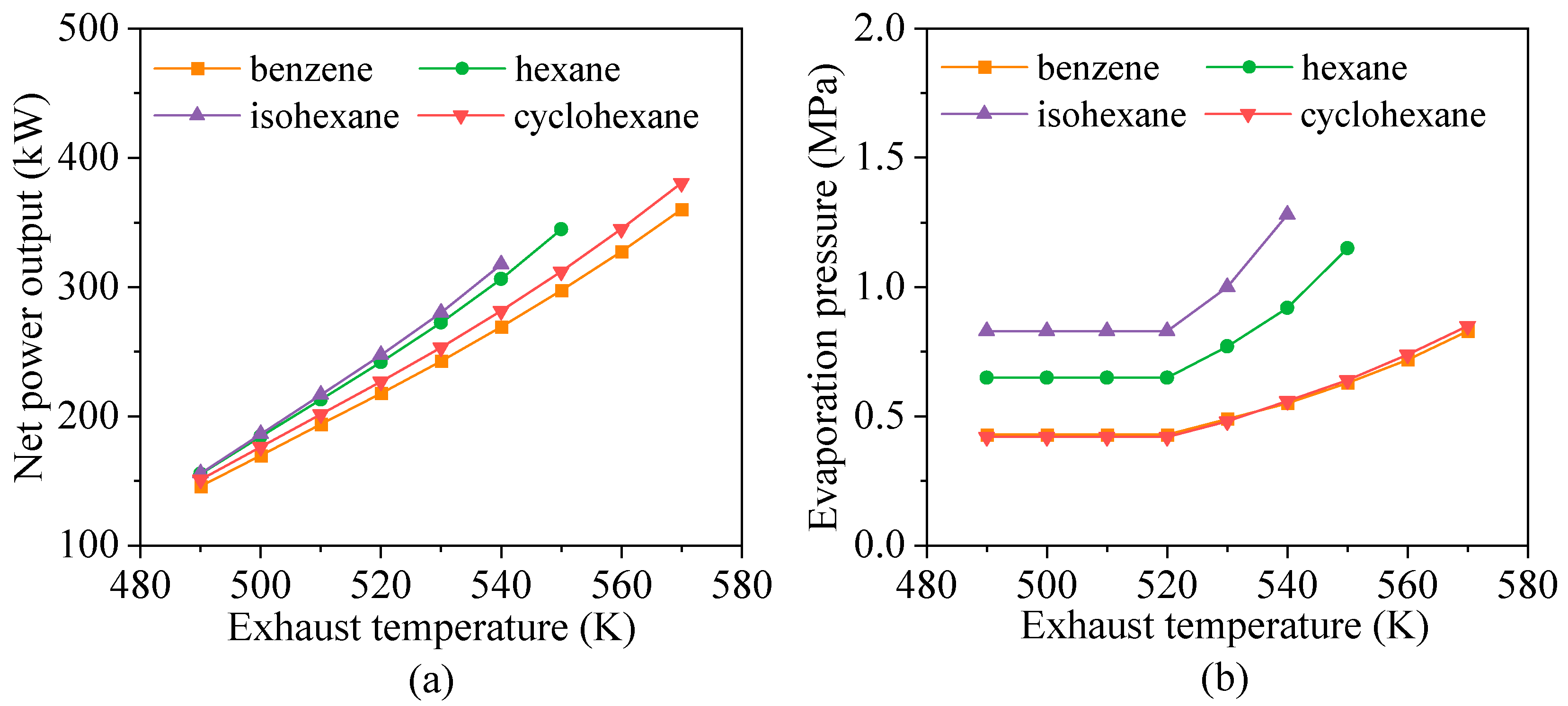
For ORC systems that recover low- to medium-grade waste heat flow, the temperature of the heat source has a significant influence on overall performance. Figure 16 illustrates the effect of exhaust gas temperature on the power output and optimal evaporation pressure of the ORC. As shown, the power outputs of benzene, hexane, isohexane, and cyclohexane vary approximately linearly with exhaust temperature. This behavior can be attributed to the fact that higher exhaust temperatures enhance the heat transfer rate in the evaporator and increase the mass flow rate of the working fluid. As shown in Figure 16b, the optimal evaporation pressure remains constant when the exhaust temperature is below 520 K. However, as the exhaust temperature increases beyond this point, the optimal evaporation pressure rises accordingly to reduce exergy loss rates in the evaporator and improve system power output.
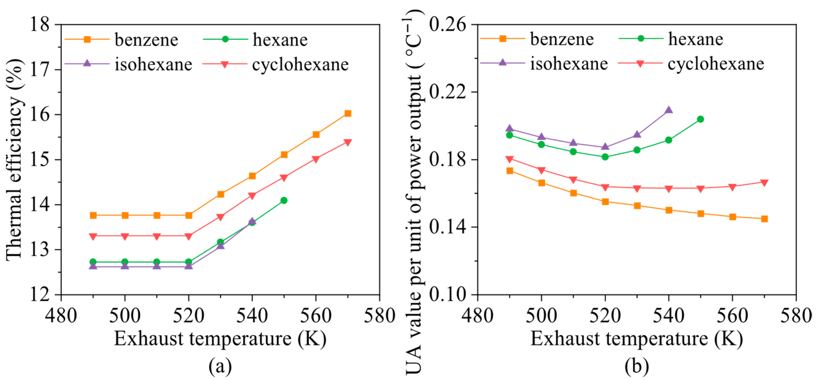
Figure 17 illustrates the effect of exhaust gas temperature on the thermal efficiency and UPR of the ORC system. As shown in Figure 17a, the thermal efficiency remains constant when the exhaust temperature is below 520 K. As the temperature increases beyond this point, both the mass flow rate of the working fluid and the evaporation pressure increase, resulting in a further rise in power output. Consequently, the thermal efficiency increases approximately linearly with exhaust temperature. Figure 17b shows that with increasing exhaust temperature, the output power of benzene increases more significantly, while the UPR of the system gradually decreases. In contrast, the UPR values of hexane, isohexane, and cyclohexane first decrease and then increase. This behavior can be explained as follows: when the exhaust temperature is below 520 K, the evaporation pressure remains unchanged. In this range, increasing the exhaust temperature leads to a higher average temperature difference for the heat transfer rate in the evaporator, but only a limited increase in the system’s overall heat transfer coefficient (UA). As the exhaust temperature continues to rise, the evaporation pressure also increases, which reduces the average temperature difference in the evaporator and results in a more substantial increase in the system UA value.
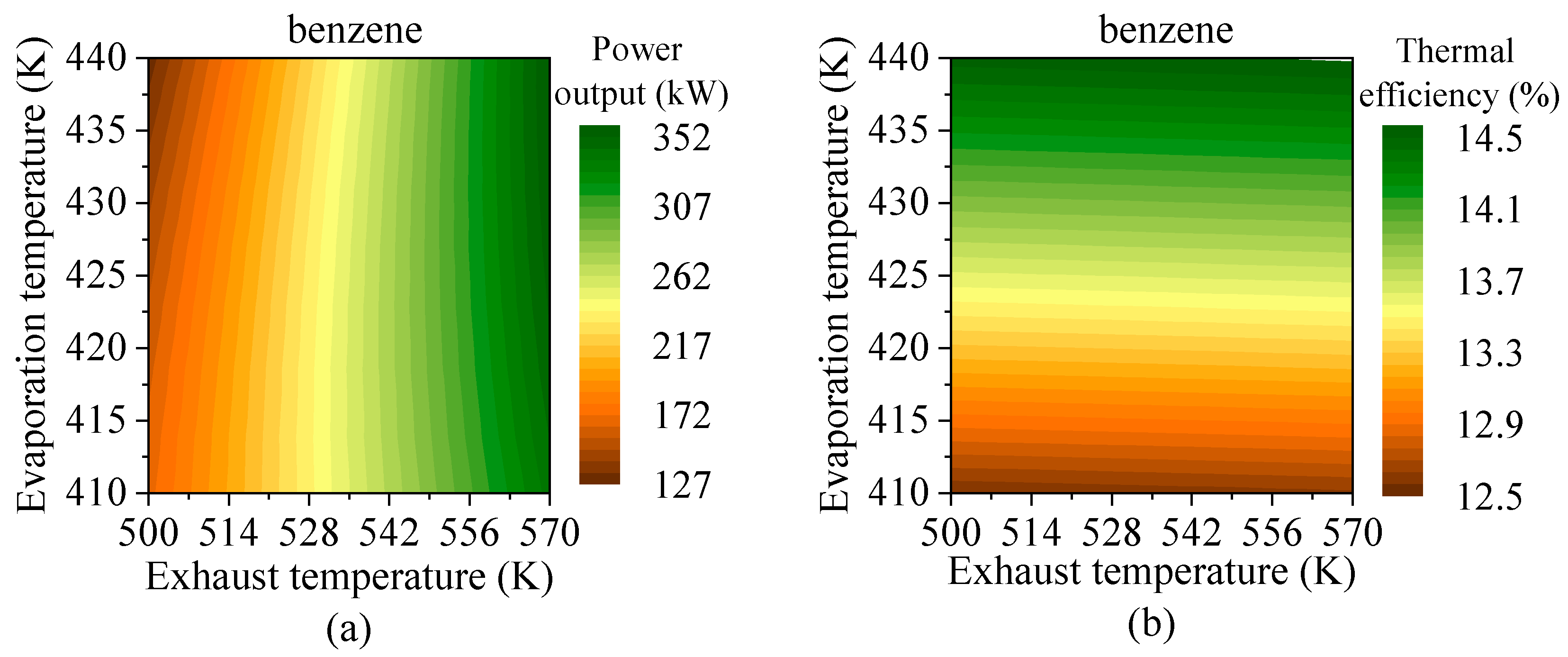
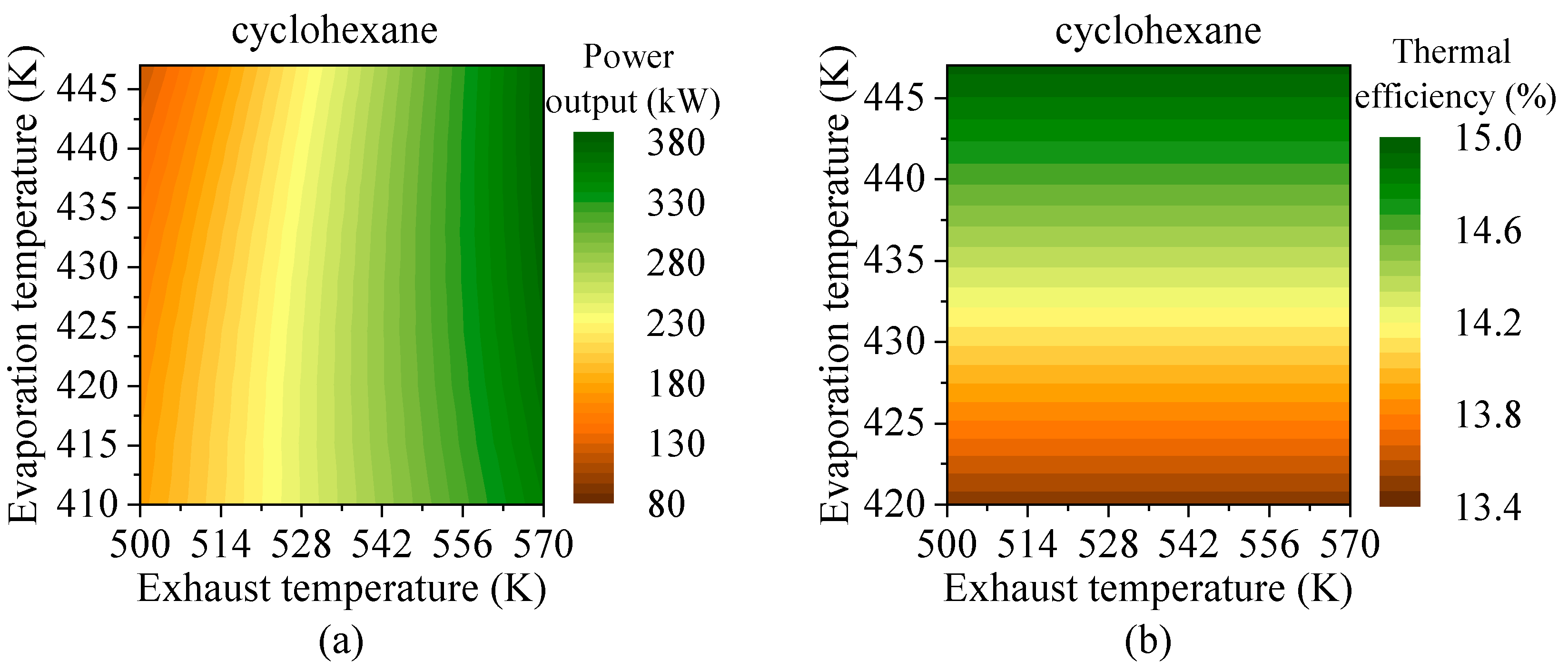
Since the performance curves of the cyclohexane, hexane, and isohexane systems exhibit similar trends under varying heat source conditions, benzene and cyclohexane were selected to investigate the effects of exhaust gas temperature and evaporation pressure on system power output and thermal efficiency. Because evaporation pressure does not directly reflect the temperature range of the working fluid, the evaporating temperature was used for analysis, as presented in Figure 18 and Figure 19. As shown, the power outputs of cyclohexane and isohexane are highly sensitive to exhaust temperature; a 10 K increase in exhaust temperature results in an approximate 12.3% rise in power output. Thermal efficiency, on the other hand, is mainly influenced by the evaporating temperature, reaching its maximum at the highest evaporating temperature of the working fluid. Therefore, within the system’s operating limitations, hydrocarbons with critical temperatures close to the exhaust temperature tend to yield better ORC performance when both the heat source temperature and the evaporating temperature are higher.
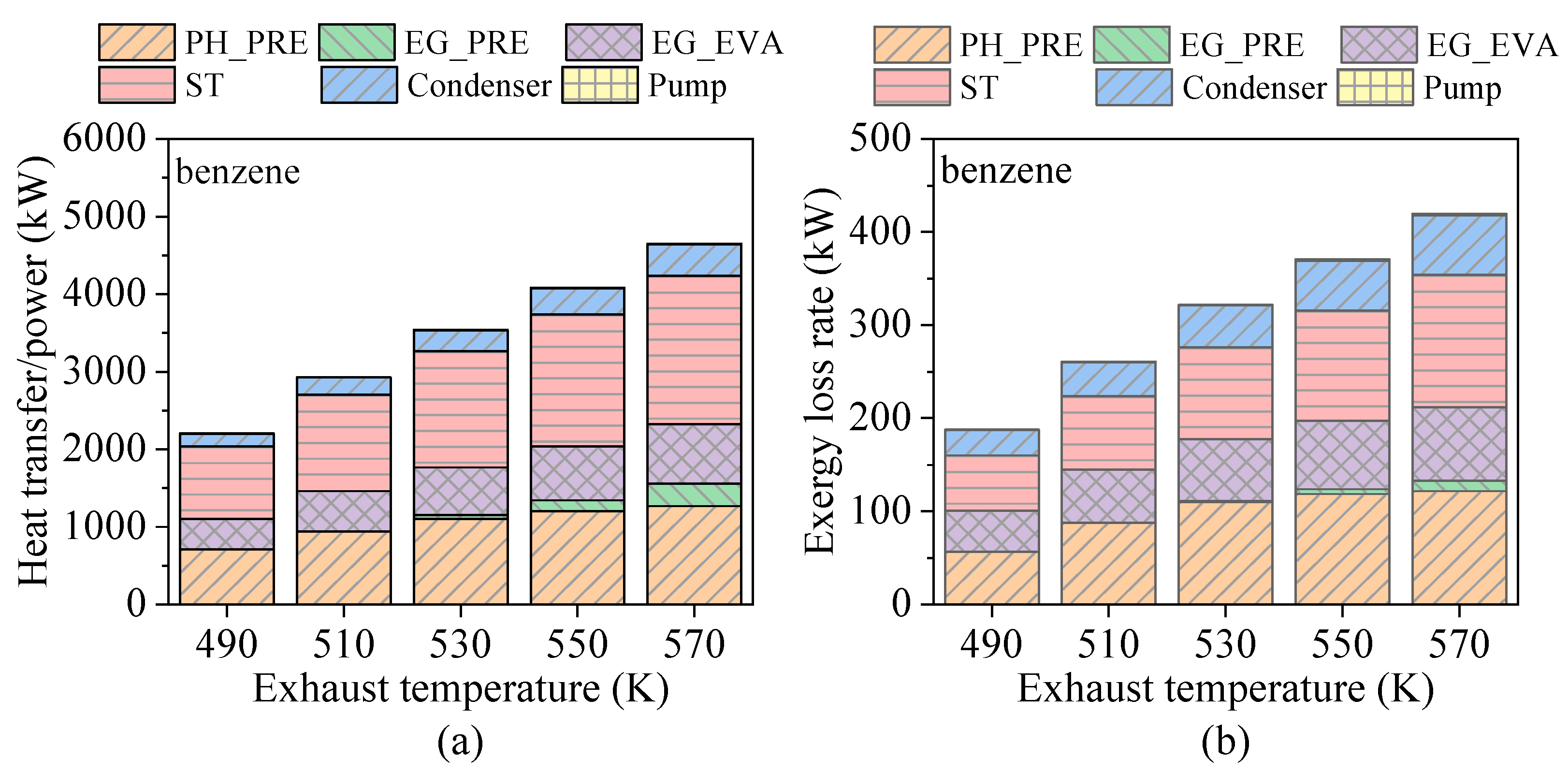
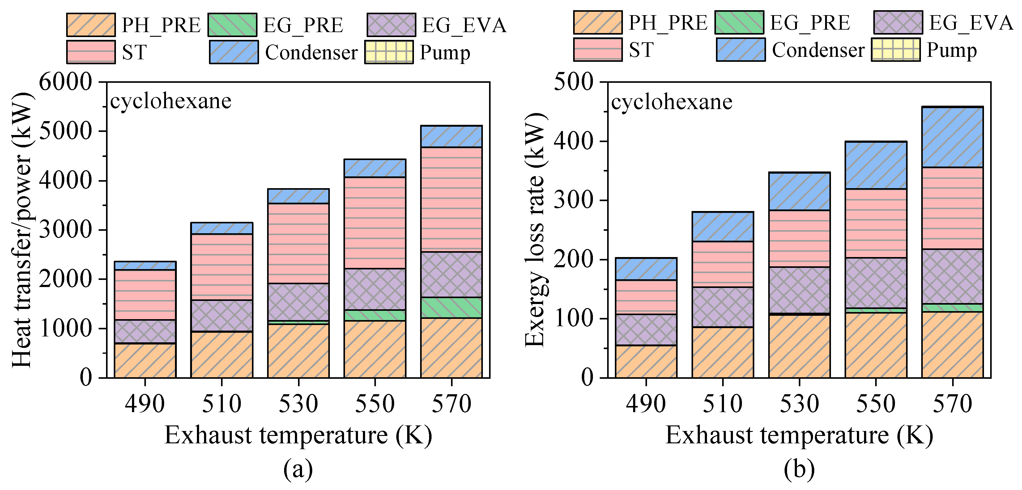
Figure 20 and Figure 21 illustrate the effects of exhaust gas temperature on the energy transfer and exergy destruction rates of ORC systems using benzene and cyclohexane. As the heat source temperature increases, both the total energy flow input and total exergy loss rate of the ORC system increase. Additionally, heat transfer and exergy loss rates in the preheating section are gradually shifted toward the preheaters in the exhaust section. Among the heat exchangers in the ORC system, the preheater in the preheating section recovers the largest portion of energy flow, accounting for approximately 57.9% of the total energy flow input, followed by the exhaust gas evaporator and the exhaust gas preheater. The expander output power accounts for about 8.5% of the total energy flow input. The optimal evaporation pressure increases with exhaust gas temperature, resulting in a gradual rise in the exergy loss rate of the condenser. Due to its lower critical temperature compared to benzene, cyclohexane exhibits a higher mass flow rate at the same exhaust temperature, which leads to a more pronounced increase in condenser exergy loss rate. When the exhaust temperature exceeds 530 K in the benzene-based ORC system, the descending order of exergy loss rate by component is as follows: expander, preheater (preheating section), exhaust gas evaporator, condenser, and exhaust gas preheater. In the cyclohexane system, the exergy loss rate of the condenser surpasses that of the exhaust gas evaporator. The power consumption and exergy loss rate of the pump are negligible in both systems.

5. Conclusions

This paper presents the design and analysis of an organic Rankine cycle (ORC) system for recovering waste heat flow from the exhaust gas, jacket water, and scavenging air of a marine two-stroke diesel engine. A thermodynamic model of the ORC system is developed, incorporating energy and exergy balance analyses. The effects of working fluid preheating temperature, evaporation pressure, and heat source temperature on system performance are investigated. Based on the results of the parametric analysis, the following conclusions are drawn:
(1)
Preheating temperature has a significant impact on system performance. For hydrocarbons with higher critical temperatures, the net power output exhibits a peak within the preheating temperature range. In contrast, for fluids with lower critical temperatures, the power output increases continuously until the maximum allowable evaporation pressure is reached. The variations in total energy flow input and exergy loss rate follow trends similar to those of net power output.
(2)
Evaporation pressure affects working fluids differently depending on their critical temperature. For hydrocarbons with higher critical temperatures, increasing evaporation pressure leads to a decline in power output but an improvement in thermal efficiency. Due to the constraint of the minimum exhaust gas outlet temperature, both total energy flow input and exergy loss rate decrease monotonically. Meanwhile, the heat transfer rate and exergy destruction rate in the exhaust gas preheater increase with rising evaporation pressure.
(7)
Heat source temperature plays a critical role in determining the energy and exergy flows distribution and overall system output. For fluids with high critical temperatures, both energy flow input and exergy loss rate rise with increasing exhaust gas temperature, while the contribution of the preheating section to total heat exchange gradually declines. For instance, in the case of cyclohexane, the net power output increases by approximately 12.3% for every 10 K rise in exhaust temperature.
Overall, isohexane was identified as the most suitable working fluid due to its relatively high net power output and wide applicable preheating temperature range. The selection was made based on the criterion of maximizing net power output, which is appropriate for marine applications where waste heat flow is continuously available and does not incur additional fuel cost.

Author Contributions

J.F.: conceptualization, methodology, validation, writing—original draft. Y.G.: software, visualization. S.H.: software, visualization. X.Z.: writing—review and editing, project administration. Y.T.: writing—review and editing. S.Z.: resources, supervision. H.Y.: writing—review and editing. G.W.: supervision, project administration. All authors have read and agreed to the published version of the manuscript.

Funding

This research was funded by the Guangdong Basic and Applied Basic Research Foundation (2024A1515030057), National Natural Science Foundation of China (No. 52571351), Basic Product Innovation Plan (DEDP-2023013), and Natural Science Foundation of Shandong Province (ZR2023ME198).

Data Availability Statement

Data will be made available on request.

Conflicts of Interest

Author Yuncheng Gu was employed by the company Weichai Power Co., Ltd. The remaining authors declare that the research was conducted in the absence of any commercial or financial relationships that could be construed as a potential conflict of interest.

Nomenclature

h Specific enthalpy [J/kg]
sSpecific entropy [J/kg K]
TTemperature [K]
UHeat transfer coefficient (kW/m2 K)
E ˙ X Exergy loss flow [kW]
AArea [m2]
I ˙ Exergy destruction rate [kW]
m ˙ Mass flow rate [kg/s]
W ˙ Power [kW]
Q ˙ Heat transfer rate [kW]
Δ T l m Pinch point temperature difference [K]
Greek symbols
η Efficiency [%]
Subscripts
inInlet
outOutlet
0Ambient condition
wfWorking fluid
hsHeat source
condCondenser
pPump
expExpander
cvControl volume
Abbreviation
IMOInternational Maritime Organization
ORCOrganic Rankine cycle
SRCSteam Rankine cycle
JWJacket water
PREPreheater
SAScavenging air
EGExhaust gas
EVAEvaporator
HFCHydrofluorocarbon
HFOHydrofluorooefin
HCHydrocarbon
HCFCHydrochlorofluorocarbon

References

  1. IMO. Fourth IMO Greenhouse Gas Study. 2025. Available online: https://www.imo.org/ (accessed on 21 July 2025).
  2. IMO. Revised MARPOL Annex VI. 2025. Available online: https://www.imo.org/ (accessed on 21 July 2025).
  3. ICCT. Long-Term Potential for Increased Shipping Efficiency Through the Adoption of Industry-Leading Practices. Available online: https://www.theicct.org.cn/ (accessed on 21 July 2025).
  4. Bouman, E.A.; Lindstad, E.; Rialland, A.I.; Strømman, A.H. State-of-the-art technologies, measures, and potential for reducing GHG emissions from shipping—A review. Transp. Res. D Transp. Env. 2017, 52, 408–421. [Google Scholar] [CrossRef]
  5. MAN Energy Solutions. How to Influence CO2. Available online: https://www.man-es.com (accessed on 21 July 2025).
  6. MAN Energy Solutions. Thermo Efficiency System for Reduction of Fuel Consumption and CO2 Emission [EB/OL]. Available online: https://www.man-es.com (accessed on 21 July 2025).
  7. LeBlanc, S. Thermoelectric generators: Linking material properties and systems engineering for waste heat recovery applications. Sustain. Mater. Technol. 2014, 1–2, 26–35. [Google Scholar] [CrossRef]
  8. Nour Eddine, A.; Chalet, D.; Faure, X.; Aixala, L.; Chessé, P. Optimization and characterization of a thermoelectric generator prototype for marine engine application. Energy 2018, 143, 682–695. [Google Scholar] [CrossRef]
  9. Aghaali, H.; Ångström, H.-E. A review of turbocompounding as a waste heat recovery system for internal combustion engines. Renew. Sustain. Energy Rev. 2015, 49, 813–824. [Google Scholar] [CrossRef]
  10. Zhu, S.; Zhang, K.; Deng, K. A review of waste heat recovery from the marine engine with highly efficient bottoming power cycles. Renew. Sustain. Energy Rev. 2020, 120, 109611. [Google Scholar] [CrossRef]
  11. Baldi, F.; Gabrielii, C. A feasibility analysis of waste heat recovery systems for marine applications. Energy 2015, 80, 654–665. [Google Scholar] [CrossRef]
  12. ICCT. Reducing Greenhouse Gas Emissions from Ships. Available online: https://theicct.org/wp-content/uploads/2021/06/ICCT_GHGfromships_jun2011.pdf (accessed on 15 August 2025).
  13. Ringler, J.; Seifert, M.; Guyotot, V.; Hübner, W. Rankine cycle for waste heat recovery of IC engines. SAE Int. J. Engines 2009, 1, 67–76. [Google Scholar] [CrossRef]
  14. Sprouse, C.; Depcik, C. Review of organic Rankine cycles for internal combustion engine exhaust waste heat recovery. Appl. Therm. Eng. 2013, 51, 711–722. [Google Scholar] [CrossRef]
  15. Gürgen, S.; Altın, İ. Novel decision-making strategy for working fluid selection in Organic Rankine Cycle: A case study for waste heat recovery of a marine diesel engine. Energy 2022, 252, 124023. [Google Scholar] [CrossRef]
  16. Li, Y.; Tang, T. Performance Analysis and Optimization of a Series Heat Exchangers Organic Rankine Cycle Utilizing Multi-Heat Sources from a Marine Diesel Engine. Entropy 2021, 23, 906. [Google Scholar] [CrossRef]
  17. McLinden, M.O.; Kazakov, A.F.; Steven Brown, J.; Domanski, P.A. A thermodynamic analysis of refrigerants: Possibilities and tradeoffs for Low-GWP refrigerants. Int. J. Refrig. 2014, 38, 80–92. [Google Scholar] [CrossRef]
  18. Liu, W.; Meinel, D.; Wieland, C.; Spliethoff, H. Investigation of hydrofluoroolefins as potential working fluids in organic Rankine cycle for geothermal power generation. Energy 2014, 67, 106–116. [Google Scholar] [CrossRef]
  19. Wang, E.H.; Zhang, H.G.; Fan, B.Y.; Ouyang, M.G.; Yang, F.Y.; Yang, K.; Wang, Z.; Zhang, J.; Yang, F.B. Parametric analysis of a dual-loop ORC system for waste heat recovery of a diesel engine. Appl. Therm. Eng. 2014, 67, 168–178. [Google Scholar] [CrossRef]
  20. Fernández, F.J.; Prieto, M.M.; Suárez, I. Thermodynamic analysis of high-temperature regenerative organic Rankine cycles using siloxanes as working fluids. Energy 2011, 36, 5239–5249. [Google Scholar] [CrossRef]
  21. Larsen, U.; Pierobon, L.; Baldi, F.; Haglind, F.; Ivarsson, A. Development of a model for the prediction of the fuel consumption and nitrogen oxides emission trade-off for large ships. Energy 2015, 80, 545–555. [Google Scholar] [CrossRef]
  22. Akman, M.; Ergin, S. An investigation of marine waste heat recovery system based on organic Rankine cycle under various engine operating conditions. Proc. IME M J. Eng. Marit. Environ. 2018, 233, 586–601. [Google Scholar] [CrossRef]
  23. Xu, B.; Rathod, D.; Yebi, A.; Filipi, Z.; Onori, S.; Hoffman, M. A comprehensive review of organic rankine cycle waste heat recovery systems in heavy-duty diesel engine applications. Renew. Sustain. Energy Rev. 2019, 107, 145–170. [Google Scholar] [CrossRef]
  24. Yang, M.-H.; Yeh, R.-H. Thermodynamic and economic performances optimization of an organic Rankine cycle system utilizing exhaust gas of a large marine diesel engine. Appl. Energy 2015, 149, 1–12. [Google Scholar] [CrossRef]
  25. Grljušić, M.; Medica, V.; Račić, N. Thermodynamic analysis of a ship power plant operating with waste heat recovery through combined heat and power production. Energies 2014, 7, 7368–7394. [Google Scholar] [CrossRef]
  26. Song, J.; Gu, C.-W. Performance analysis of a dual-loop organic Rankine cycle (ORC) system with wet steam expansion for engine waste heat recovery. Appl. Energy 2015, 156, 280–289. [Google Scholar] [CrossRef]
  27. Ahlgren, F.; Mondejar, M.E.; Genrup, M.; Thern, M. Waste heat recovery in a cruise vessel in the baltic sea by using an Organic Rankine Cycle: A Case Study. J. Eng. Gas Turbines Power Trans. ASME 2016, 138, 011702. [Google Scholar] [CrossRef]
  28. Yuksek, E.; Mirmobin, P. Waste heat utilization of main propulsion engine jacket water in marine application. In Proceedings of the 3rd International Seminar on ORC Power Systems, Bruxelles, Belgium, 12–14 October 2015. [Google Scholar]
  29. Song, J.; Song, Y.; Gu, C. Thermodynamic analysis and performance optimization of an Organic Rankine Cycle (ORC) waste heat recovery system for marine diesel engines. Energy 2015, 82, 976–985. [Google Scholar] [CrossRef]
  30. Tayyeban, E.; Deymi-Dashtebayaz, M. Optimizing an expansion engine-based organic rankine cycle system for heat recovery from natural gas engines. Energy Convers. Manag. 2025, 343, 120209. [Google Scholar] [CrossRef]
  31. Zhang, X.; Wang, X.; Shi, L.; Tian, H.; Shu, G. Organic Rankine cycle configuration design method based on the performance of all operating conditions. Energy 2025, 331, 137019. [Google Scholar] [CrossRef]
  32. Chys, M.; van den Broek, M.; Vanslambrouck, B.; De Paepe, M. Potential of zeotropic mixtures as working fluids in organic Rankine cycles. Energy 2012, 44, 623–632. [Google Scholar] [CrossRef]
  33. Wang, E. Low and Medium Temperature Power Cycle Systems and Applications; Beijing Institute of Technology Press: Beijing, China, 2021. [Google Scholar]
  34. Garrido, J.M.; Quinteros-Lama, H.; Mejía, A.; Wisniak, J.; Segura, H. A rigorous approach for predicting the slope and curvature of the temperature-entropy saturation boundary of pure fluids. Energy 2012, 45, 888–899. [Google Scholar] [CrossRef]
  35. Zhu, S.; Feng, J.; Tang, Y.; Bai, S.; Deng, K. Influence of ambient conditions on the marine two-stroke engine integrated with a bottoming Rankine cycle system: Energy and exergy analyses. Appl. Therm. Eng. 2023, 219, 119601. [Google Scholar] [CrossRef]
  36. Baldi, F.; Larsen, U.; Gabrielii, C. Comparison of different procedures for the optimisation of a combined Diesel engine and organic Rankine cycle system based on ship operational profile. Ocean. Eng. 2015, 110, 85–93. [Google Scholar] [CrossRef]
  37. Zhu, Y.D.; Jiang, L.; Zhou, Y.D.; Yu, L.J. An Integrated Comparison for Working Fluids Selection in Both Subcritical and Supercritical ORC. Adv. Mat. Res. 2014, 997, 703–712. [Google Scholar]
  38. Zhu, S.; Gu, Y.; Yuan, H.; Ma, Z.; Deng, K. Thermodynamic analysis of the turbocharged marine two-stroke engine cycle with different scavenging air control technologies. Energy 2020, 191, 116533. [Google Scholar] [CrossRef]
  39. Andreasen, J.; Meroni, A.; Haglind, F. A Comparison of Organic and Steam Rankine Cycle Power Systems for Waste Heat Recovery on Large Ships. Energies 2017, 10, 547. [Google Scholar] [CrossRef]
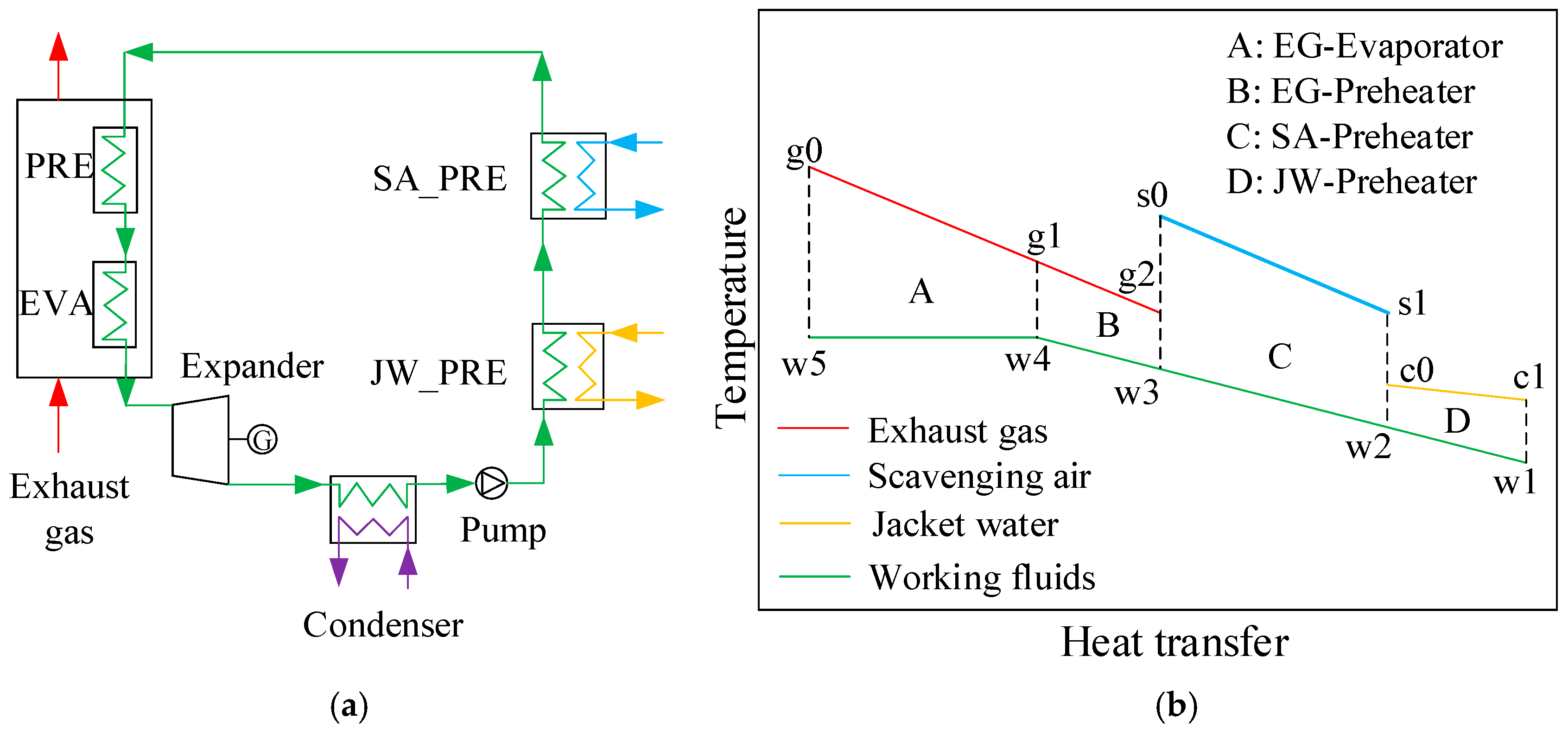
Figure 1. ORC system: (a) configuration and (b) temperature heat transfer diagram.
Jmse 13 01679 g001
Figure 2. ORC system calculation flowchart.
Jmse 13 01679 g002
Figure 3. Effects of preheating temperature on the (a) optimum evaporation pressure and (b) net power output of ORC.
Jmse 13 01679 g003
Figure 4. Effects of preheating temperature on thermal efficiency of ORC.
Jmse 13 01679 g004
Figure 5. Effects of preheating temperature on UA value per unit of power output in ORC.
Jmse 13 01679 g005
Figure 6. Effects of preheating temperature on exergy loss rate of each heat exchanger in ORC.
Jmse 13 01679 g006
Figure 7. Heat transfer matching in ORC at the preheating temperature of (a) 80 °C, (b) 145 °C, and (c) 180 °C.
Jmse 13 01679 g007
Figure 8. Effects of preheating temperature on the (a) energy and (b) exergy distributions in the ORC of isohexane.
Jmse 13 01679 g008
Figure 9. Effects of preheating temperature on the (a) energy and (b) exergy distributions in the ORC of pentane.
Jmse 13 01679 g009
Figure 10. Effects of preheating temperature on the (a) energy and (b) exergy distributions in the ORC of R1233zd(E).
Jmse 13 01679 g010
Figure 11. Effects of evaporation pressure on the net power output of the ORC system.
Jmse 13 01679 g011
Figure 12. Effects of evaporation pressure on expander output power, pump power consumption, and mass flow rate.
Jmse 13 01679 g012
Figure 13. Effects of evaporation pressure on (a) thermal efficiency and (b) UA value per unit of power output in ORC.
Jmse 13 01679 g013
Figure 14. Effects of evaporation pressure on the (a) energy and (b) exergy distributions in the ORC of isohexane.
Jmse 13 01679 g014
Figure 15. Effects of evaporation pressure on the (a) energy and (b) exergy distributions in the ORC of cyclohexane.
Jmse 13 01679 g015
Figure 16. Effects of exhaust temperature on (a) power output and (b) optimal evaporation pressure of ORC.
Jmse 13 01679 g016
Figure 17. Effects of exhaust temperature on (a) thermal efficiency and (b) UA value per unit of power output in ORC.
Jmse 13 01679 g017
Figure 18. Effects of exhaust and evaporation temperatures on (a) power output and (b) thermal efficiency in the ORC of benzene.
Jmse 13 01679 g018
Figure 19. Effects of exhaust and evaporation temperatures on (a) power output and (b) thermal efficiency in the ORC of cyclohexane.
Jmse 13 01679 g019
Figure 20. Effects of exhaust temperature on (a) energy and (b) exergy distributions in the ORC of benzene.
Jmse 13 01679 g020
Figure 21. Effects of exhaust temperature on (a) energy and (b) exergy distributions in the ORC of cyclohexane.
Jmse 13 01679 g021
Table 1. Physical parameters of the working fluid.
Working FluidsCategorizationCritical Temperature (K)Critical Pressure (kPa)
benzeneHCs562.024907
hexaneHCs507.823034
isohexaneHCs497.73040
cyclohexaneHCs553.64081
pentaneHCs469.73370
R245caHFCs447.573941
R1233zd(E)HFOs438.753571
Table 2. Engine specifications.
TypeTwo-Stroke, In-Line, Six-Cylinder, Turbocharged, Diesel Engine
Bore × Stroke340 × 1600 mm
Compression ratio19.8:1
Connecting rod length1600 mm
Rated speed and power157 r/min @ 4896 kW
Displacement volume145.3 l/cylinder
Table 3. Design parameters of the ORC.
ParameterValue
Component efficiencyEfficiency of expander (%)72
Efficiency of pump (%)70
Efficiency of gear/generator (%)93
Heat exchanger designMinimum PPTD in the evaporator (°C)20
Minimum PPTD in the scavenging air cooler (°C)10
Temperature after the jacket water cooler (°C)80
Condensation temperature (°C)35
ConstraintsMaximum evaporation pressure (bar) 0.8 · P crit
Minimum exhaust temperature out of evaporator (°C)145
Minimum preheater outlet scavenging air temperature (°C)90
Table 4. Preheating temperature of each working fluid.
Working FluidsCritical Temperature
(°C)
Critical Pressure
(kPa)
Preheating Temperature
(°C)
Maximum Power Output
(kW)
benzene288.874907135217.84
hexane234.673034140242.04
isohexane224.553040145247.44
cyclohexane280.454081135226.91
pentane196.553370180281.38
R245ca174.423941160343.10
R1233zd(E)165.63571150331.64
Disclaimer/Publisher’s Note: The statements, opinions and data contained in all publications are solely those of the individual author(s) and contributor(s) and not of MDPI and/or the editor(s). MDPI and/or the editor(s) disclaim responsibility for any injury to people or property resulting from any ideas, methods, instructions or products referred to in the content.