Abstract
This study examines advanced electrospark alloying (ESA) as a pulse-driven surface hardening technique for marine engineering components operating in corrosive and abrasive environments. Coatings were deposited using cobalt-based (Stellite 6), nickel-based (NiCrBSi), titanium-based (VT1-0), and boron-based (B4C) electrodes, with pulse energies of 0.2–0.5 J, discharge frequencies of 100–200 Hz, electrode feed rates of 5–8 mm/min, applied loads of 15–20 N, and treatment durations of 40–60 s. The effects of processing parameters on coating microstructure, adhesion strength, microhardness, corrosion resistance, and wear behaviour were systematically evaluated. ESA treatments increased microhardness by 35–48% and adhesion strength by 22–30%, while reducing the corrosion rate from 0.043 mm/year to 0.025–0.027 mm/year and lowering wear volume loss by 40–47%. Compared with high-velocity oxy-fuel (HVOF) spraying and laser hardening, ESA achieved 37–58% lower energy consumption and 40–70% lower CO2 emissions. These findings highlight ESA as an energy-efficient and environmentally sustainable option for on-site maintenance and modernisation of maritime equipment.
1. Introduction
Modern surface engineering technologies for strengthening metal components are increasingly aimed at enhancing performance while minimising environmental impact. In the context of global climate challenges and the energy transition, it is essential to implement technological solutions that combine high efficiency, repairability, and sustainability. One promising method is electrospark alloying (ESA)—a localised, energy-efficient technique that enables the formation of wear-, corrosion-, and heat-resistant coatings without the use of hazardous chemicals or high-temperature processing environments.
ESA is particularly relevant to the maritime industry, where ship components are continuously exposed to harsh tribological conditions, including friction, saltwater corrosion, cavitation, and thermal cycling. Such factors critically affect the surface integrity and reliability of propulsion units, hydraulic systems, and engine components, with failures often originating in surface layers subjected to constant dynamic and chemical stresses. ESA offers rapid, on-site surface restoration, supporting the principles of the circular economy and significantly reducing both material costs and environmental impact.
Contemporary surface modification technologies—such as thermal spraying methods, including high-velocity oxy-fuel (HVOF) and cold spray—are well documented in the literature [1,2,3,4], with case studies confirming improvements in coating density, oxidation resistance, and adhesion [2,5,6,7,8]. Other studies address thermal barrier coatings (e.g., ZrO2–Y2O3) [9], high-temperature oxide films [10,11,12], and anticorrosive coatings such as WC–Ni [13] and chromium-based systems [14,15], particularly in marine and hydraulic applications.
ESA has been investigated extensively in both classical and modern contexts—from early studies on material transfer processes [16,17] to recent advances in nanostructuring, surface hardening, and nanophase formation [15,18,19]. Hybrid approaches, such as ESA combined with ultrasonic impact treatment, have shown further potential [20]. Novel research directions include machine learning-assisted modelling of high-entropy alloy coatings [12,21,22], ion implantation [23], and surface modification of titanium-based materials for high-strength and biomedical applications [24,25,26,27,28,29,30,31,32,33,34].
In the context of the present study, scientific works [35,36,37] demonstrate the use of accurate mathematical and numerical modelling methods for predicting the stress–strain state of structural elements under impulse and shock loads, which is important for optimising ESA modes and impulse strengthening of part surfaces. Despite the growing body of work, the specific application of ESA in the maritime sector remains underexplored—particularly regarding the influence of process parameters and electrode composition on coating microstructure and performance under marine operating conditions. This gap forms the basis for a systematic investigation of the ESA physicochemical principles and its role in surface repair and reinforcement strategies for marine machinery.
The operational reliability of marine technical systems largely depends on the ability to protect and restore components operating under high mechanical stress, aggressive seawater, and cavitation. Traditional surface hardening and restoration technologies for marine applications—such as HVOF spraying, cold spraying, laser and induction hardening, and electroplating—offer high density, wear resistance, and corrosion protection. However, most require controlled atmospheres, high-temperature processing, bulky equipment, and specialised facilities, making them unsuitable for on-board application. Moreover, some, such as electroplating, involve toxic reagents, posing environmental risks in marine environments [38,39].
ESA combines localised energy input, low environmental impact, and the ability to process complex geometries to produce wear-, corrosion-, and heat-resistant coatings without inducing significant thermal stresses in the substrate. Modern developments include integrating electrical discharge machining with ultrasonic processing, nanostructuring, and the use of high-entropy alloy electrodes, thereby improving coating adhesion strength and durability [40]. Recent studies [41,42] highlight approaches to ESA surfacing and coating modification aimed at enhancing wear, corrosion, and tribocorrosion resistance in complex environments, including seawater.
This study aims to address the above research gap by developing and testing an ESA methodology adapted for application on ships without dismantling equipment or transporting it to specialised centres. The proposed approach enables environmentally sound and efficient repairs, minimises downtime, and reduces maintenance costs in the maritime industry. The scientific novelty lies in the comprehensive investigation of structural and phase transformations in ESA-produced coatings specifically for marine applications. The research experimentally validates the effects of key process parameters, such as discharge frequency and pulse energy, on coating microhardness and adhesion. A technological ESA model has been developed for environmentally constrained shipboard conditions, demonstrating the method’s potential as a resource- and energy-efficient solution for ship repair in real maritime environments.
The principal aim of this study is to further assess the technological capabilities of ESA for improving operational reliability and extending the service life of marine components. The influence of ESA parameters on the microstructure and phase composition of treated surfaces is examined, the role of electrode material in determining hardness, adhesion, and wear resistance is evaluated, and a process model specifically tailored for marine applications is developed. Furthermore, ESA is compared with conventional surface treatments to ensure compatibility with practical ship repair and maintenance procedures.
The broader context includes ongoing efforts to improve the efficiency and safety of maritime operations through environmentally responsible technologies. Studies such as [43,44,45,46,47,48] explore low-sulphur fuels, hydrogen energy, energy-optimised systems, and ship structural integrity—all highlighting the need for integrated solutions in marine sustainability.
By addressing both technological and practical aspects of ESA, this work contributes to sustainable maintenance strategies aligned with modern ecological and operational demands in the maritime sector.
In summary, although ESA has been widely studied in various industrial contexts, its systematic evaluation for marine engineering applications—particularly under in-service conditions—remains limited. This study addresses that gap by experimentally linking ESA process parameters and electrode material selection to coating microstructure, adhesion, hardness, and resistance to wear and corrosion in seawater environments. Building on recent advances in ESA technology, we propose and validate a process model tailored to shipboard constraints, ensuring operational feasibility and environmental compliance. The following sections describe the materials, equipment, and experimental procedures used to implement and assess the proposed methodology.
2. Materials and Methods
In this study, electrospark alloying (ESA) technology was employed to fabricate functional surface coatings on steel specimens. The process was conducted using pulsed electric discharges, facilitating localised transfer of electrode material onto the treated surfaces. Alloying electrodes in the form of rods composed of various cobalt-, titanium-, boron-, and nickel-based alloys were utilised.
The experimental data were processed and statistically analysed using Microsoft Excel 2021 (Microsoft Corp., Redmond, WA, USA). Graphs and diagrams were created using OriginPro 2023 (OriginLab Corp., Northampton, MA, USA). Microstructural images obtained via optical and scanning electron microscopy were examined using ImageJ 1.54f (National Institutes of Health, Bethesda, MD, USA). Schematic illustrations and equipment drawings were prepared using AutoCAD 2023 (Autodesk Inc., San Rafael, CA, USA).
The study was carried out using the electrospark alloying (ESA) technology on samples made of AISI 316L steel and S355 structural steel, which are typical for ship machinery components (shafts, bearings, sealing elements). The treatment was carried out in an air environment at a temperature of 20–25 °C, without the use of protective gases or coolants.
Rod electrodes made of cobalt, nickel, boron-containing and titanium alloys were used for coating. The chemical composition and brands of the electrodes are shown in Table 1 (EN and UNS designations). The manufacturers are Oerlikon Metco AG (Wohlen, Switzerland) and Weldstone GmbH (Burbach, Germany). The classification of electrodes follows the international standards EN ISO 24373 [49] and EN ISO 18274 [50], as specified in Table 1.

Table 1.
Chemical composition and designation of alloying electrodes used in ESA experiments.
The experimental setup included a pulse generator of the EIL-8M type with an adjustable frequency of 400–1000 Hz and a pulse energy of 0.05–5.0 J, a mechanism for vertical electrode vibrations with an amplitude of 0.1–0.5 mm, and a system for monitoring the interelectrode gap. The properties of the coatings were monitored using a Future-Tech FM-800 microhardness tester, a JEOL JSM-IT500 scanning electron microscope, a PosiTest AT-M adhesion tester, and an ASCOTT CC450iP salt spray chamber (testing in 5% and 10% NaCl solutions).
Following the identification of electrode compositions (Table 1), the corresponding ESA process parameters applied for each electrode type are presented in Table 2. These parameters were established through preliminary optimisation experiments to ensure uniform coating formation, stable adhesion, and the targeted mechanical and corrosion-resistant properties under marine operating conditions.

Table 2.
ESA process parameters used in the study.
The ESA process parameters listed in Table 2 were used to form the coatings on the samples, after which tests for microhardness, adhesion, corrosion resistance, and wear resistance were performed in accordance with standard methods.
The experimental research plan included 48 series of sample processing, within which the pulse frequency, energy, electrode material, and processing time were varied. For each series, at least three repeated measurements of microhardness and adhesion were performed. The mathematical model of the ESA process was developed in MATLAB R2024a using partial differential equations of thermal conductivity and Stefan’s conditions to describe the phase transition. COMSOL Multiphysics 6.1 software was used to verify the model. The model was adapted to the limitations of the on-board environment (vibrations, limited access to the cell, fluctuations in the supply voltage) by introducing appropriate correction factors into the calculations.
Figure 1 presents a schematic diagram of the electrospark alloying (ESA) process used in this study, illustrating the interaction between the alloying electrode and the workpiece, the formation of spark discharges, and the key process parameters: current (I), pulse energy (E), and pulse frequency (f).
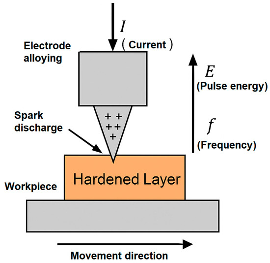
Figure 1.
Schematic diagram of the electrospark alloying (ESA) process (the ‘+’ symbols indicate the discharge sparks that occur between the electrode and the workpiece surface during pulsed treatment).
The treatment was performed in ambient air, without the need for vacuum chambers, inert gas atmospheres, or liquid coolants. This not only reduces overall energy consumption, but also eliminates the production of hazardous waste, an important consideration from an environmental sustainability standpoint.
ESA is particularly well-suited for the restoration and surface protection of marine machinery components, including shafts, bearings, propellers, pistons, and seals. These parts operate in highly saline environments that demand exceptional resistance to wear and corrosion, properties that can be achieved by generating hardened surface layers enriched with amorphous or carbide-phase inclusions.
To streamline and standardise the ESA process for marine applications, a decision-making algorithm is proposed for selecting appropriate electrode materials, processing parameters, and treatment zones (see Table 3). This framework is designed to facilitate efficient adaptation of ESA technology in real-world maritime maintenance scenarios.

Table 3.
Indicative classification of ESA parameters for marine parts.
The sequence of the electrospark alloying (ESA) process includes several main stages that ensure the effective formation of a protective coating, Figure 2.
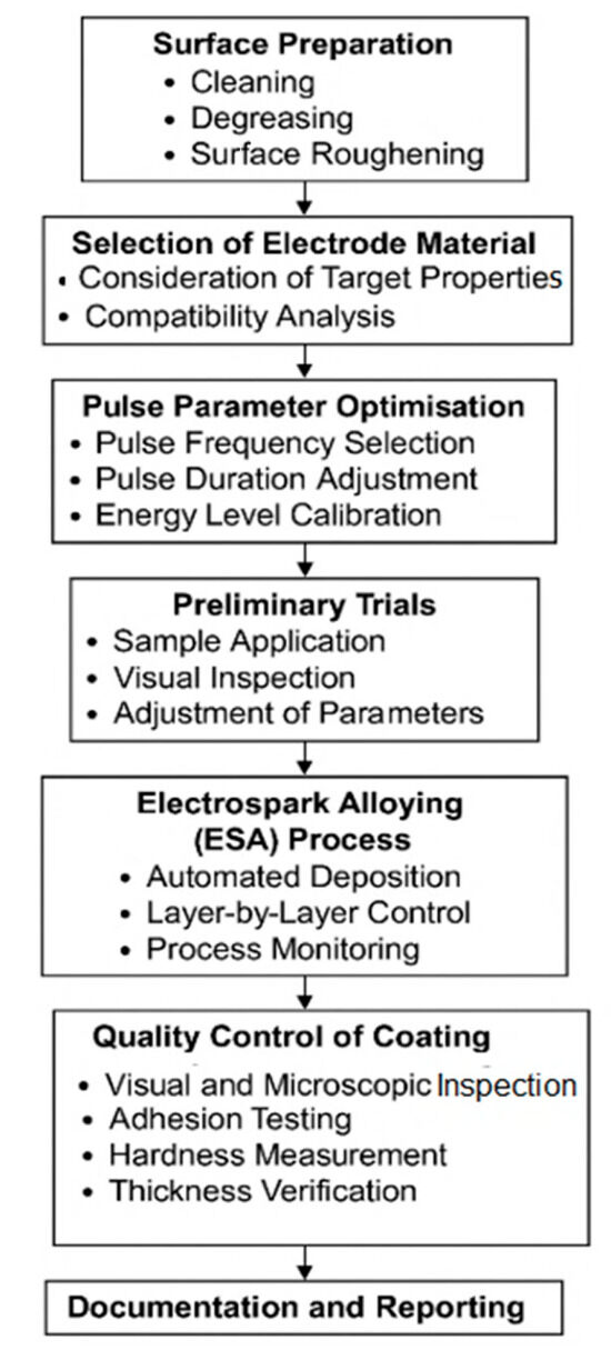
Figure 2.
Flowchart of the electrospark alloying (ESA) process.
These steps ensure the production of high-quality, reliable coatings and guarantee the reproducibility of results during the electrospark alloying process.
The experimental setup for electrospark alloying (ESA) included an EIL-8M pulse generator with a frequency control range of 400–1000 Hz and a pulse energy of 0.05–5.0 J, a mechanical electrode feeding system with an adjustable vibration amplitude of 0.1–0.5 mm, and an electrode gap control unit.
To control the properties of the coatings, a Future-Tech FM-800 microhardness tester, a JEOL JSM-IT500 scanning electron microscope, a PosiTest AT-M adhesion tester, and an ASCOTT CC450iP salt spray chamber for corrosion tests in 5% and 10% NaCl solutions were used.
The research plan included 48 series of ESA treatments of AISI 316L and S355 steel samples with the following parameters varied:
- pulse frequency: 400, 600, 800, 1000 Hz;
- pulse energy: 0.05; 0.1; 0.5; 1.0; 5.0 J;
- electrode material: according to Table 1;
- treatment duration: 20–180 s.
For each series, at least three repeated measurements of microhardness and adhesion were performed, and the microstructure was analysed, Figure 3.
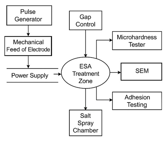
Figure 3.
Experimental setup for the ESA process.
The mathematical modelling of the ESA process was performed in MATLAB R2024a using the equations of thermal conductivity and modified Stefan conditions to describe phase transitions. To verify the model, COMSOL Multiphysics 6.1 was used, where the geometry of the sample and electrode was implemented, the thermophysical properties of materials and the influence of shipboard conditions (vibrations, voltage fluctuations, limited access to the element) were taken into account.
3. Comparison of ESA with Other Surface Hardening Methods
Electrospark alloying (ESA) offers several advantages over conventional surface hardening techniques, particularly in applications requiring localised treatment, minimal environmental impact, and adaptability to complex geometries. ESA enables targeted modification of surface layers without the need for extensive surface preparation, making it especially suitable for hard-to-access or geometrically intricate areas.
In contrast to thermal spraying and laser hardening methods, ESA does not require a controlled atmosphere (e.g., protective gas) or high-temperature processing. This not only reduces energy consumption, but also allows for on-site application in field conditions, including at marine transport facilities where access to specialised infrastructure may be limited.
Table 4 provides a comparative overview of ESA and selected standard surface hardening technologies, highlighting differences in operational requirements, environmental impact, and practical applicability.

Table 4.
Comparison of ESA and other surface treatment methods.
The ESA process flowchart for marine components, presented in Figure 4, outlines the complete life cycle of electrospark alloying, from the initial damage assessment to the final integration of the refurbished part into a marine equipment assembly. The unique challenges of the marine environment, including exposure to saltwater, cavitation, mechanical vibrations, and chemical attack, are integral to the process design.
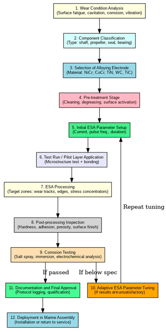
Figure 4.
Detailed diagram of the ESA process for marine parts.
The procedure begins with an analysis of typical surface defects such as fatigue, wear, and corrosion. Based on this evaluation, the component is classified, and a suitable alloying electrode is selected (e.g., NiCr, CoCr, WC, TiN). Subsequent steps include surface pre-treatment, configuration of ESA processing parameters, trial coating application, and microstructural inspection of the coating. Following successful preliminary assessment, the process continues with full-scale treatment and post-coating quality control tests. If the coating performance fails to meet the specified standards, an adaptation loop is initiated in which processing parameters are adjusted and retested until the required properties are achieved.
Figure 4 shows a flowchart illustrating the main stages of implementing the electrospark alloying process for the restoration and protection of marine components. Each step is aimed at increasing the wear resistance and durability of the parts.
The step-by-step implementation of all procedures, including parameter settings, quality control and corrosion resistance testing, ensures the reliability of the coating and compliance of marine components with the technical requirements of operation.
A critical element of the ESA workflow is the parameter adjustment module, which is activated when the resulting coating properties deviate from the specified requirements. This feedback loop ensures both flexibility and reproducibility of the process, even under variable operational or environmental conditions, an essential advantage for marine applications.
The final stages of the ESA process, including corrosion resistance testing, technical documentation, and qualification procedures, are designed to comply with certification standards and safety regulations governing marine transport systems. This systematic approach aligns with the core principles of reliability, maintainability, and environmental responsibility in maritime engineering.
The properties of steel components can be modified by altering their chemical composition or microstructure through various external energy inputs, such as mechanical, thermal, or electrical treatment. Among these, electrospark alloying (ESA) is distinguished by its capacity to deliver highly localised micro-scale energy pulses without significantly affecting the bulk properties of the base material. This makes ESA particularly advantageous for precision surface modification in applications where structural integrity must be preserved.
The microhardness of the coatings was measured by the Vickers method using an HM-210 microtester (Mitutoyo, Japan) with a load of 100 g (0.98 N) and a dwell time of 10 s. Measurements were taken in three different areas of each sample, and the mean value was calculated from five indents per area.
The corrosion behaviour of the coatings was evaluated in a salt spray chamber SF/450 (Ascott Analytical, Tamworth, UK) in accordance with ASTM B117-19 [51]. The NaCl solution concentration was 5 wt%, and the chamber temperature was maintained at 35 ± 2 °C. The test lasted 72 h to simulate accelerated conditions equivalent to approximately 6–8 months of service in a typical marine environment. This duration is widely adopted in research to ensure result comparability and to prevent excessive accumulation of corrosion products that could distort interpretation.
4. Technological Fundamentals of Electrospark Alloying (ESA)
4.1. Integrated Mathematical–Physical Model of the ESA Process
Electrospark alloying (ESA) operates on the principle of pulsed electrical discharges between a compact anode (typically the alloying electrode) and a cathode (the workpiece surface). These discharges result in localised electrical erosion of the anode and the subsequent transfer and solidification of its material onto the cathode surface. The process initiates when the anode approaches the cathode closely enough to cause dielectric breakdown of the interelectrode gap.
Breakdown typically occurs under the influence of vibrational and transitional phenomena, even at sub-Paschen-gap distances. Characteristic breakdown parameters include voltage levels in the range of Up = 15–200, frequencies between 50 and 300 Hz, and interelectrode distances from 0.01 to 10 µm.
From a theoretical standpoint, the ESA process can be modelled as a sequence of interrelated physical phenomena involving pulsed energy input, transient local heating, phase transformation, melt pool dynamics, diffusion, and interfacial evolution. A combination of thermodynamic, electromagnetic, and mechanical equations governs this complex interaction. The energy delivered during each spark discharge can be expressed as follows:
where Q is the impulse energy, I is the current (A), U is the discharge voltage (V), and τ is the pulse duration (s). This energy determines the re-solidified metal volume and the alloying layer’s penetration depth. For typical ESA regimes (I = 30–100 A, U = 30–100 V, τ = 50–500 μs), the energy per pulse ranges from 0.05 to 5 J, forming localised thermal micro-craters with layer depths of 10–200 μm.
This energy is locally concentrated in the microcontact zone and causes rapid heat diffusion, which is described by the transient heat conduction equation:
with α = κ/ρcp representing thermal diffusivity. The penetration depth of the temperature wave during a single pulse can thus be estimated by the following:
Cumulative heating and melting effects over N pulses lead to the growth of a hardened surface layer:
where k is an empirical coefficient, dependent on material and electrode type. Within the melt zone, the material transfer can be modelled by the Stefan conditions at the solid–liquid interface:
This describes phase transformation and latent heat release at the moving interface s(t). Further, the intensity of local energy input per unit area (surface power density) is as follows:
where f is the frequency of pulses and A is the spark-affected area. This determines melting rates and influences the morphology of the modified layer.
From a mechanical standpoint, the fatigue resistance of the coating is governed by adhesion degradation, which follows a logarithmic law:
where σ0 is the initial adhesion and α is the degradation coefficient. This function is a prognostic tool for evaluating coating longevity in high-cycle applications such as marine systems.
The pulse energy formula sets the initial volume of thermal power, which is then distributed according to the laws of thermal conductivity; the estimation of the penetration depth of this power allows for predicting the temperature distribution and the depth of material hardening; the Stefan conditions correctly describe the phase transition in the molten layer, and the empirical laws of layer thickness accumulation and adhesion degradation ensure that the cumulative effects of a series of pulses are taken into account during repeated processing.
The ESA process creates a non-equilibrium thermomechanical system characterised by dynamic energy and mass exchange at microcontacts. Implementing this model numerically allows for real-time control of coating growth, optimisation of energy input, and accurate prediction of long-term operational behaviour under corrosive and mechanical stress.
This localised energy input ensures minimal thermal impact on surrounding areas, eliminating the need for cooling media, protective gases, or high-temperature ovens. Consequently, ESA is a low-emission and eco-friendly technology. In contrast to conventional thermal spraying or bulk heat treatment, ESA produces highly adherent coatings without overheating surrounding areas or requiring shielding gases, thus minimising environmental impact. There are no harmful vapours, solvents, or high-temperature waste. Additionally, due to the pulse-based nature of the process, total energy consumption is significantly lower than that of continuous thermal methods. This aligns ESA with the goals of energy-efficient and low-emission technologies, particularly for marine repair operations, where mobile, precise, and non-polluting techniques are crucial.
According to the results of tests in salt fog (NaCl, 5%, 720 h), the corrosion rate decreased from 0.043 mm/year for the base metal to 0.025–0.027 mm/year for ESA coatings. This corresponds to a 37–42% reduction in the corrosion rate, which significantly increases the durability of parts in marine conditions.
The results of the corrosion resistance tests of the ESA coatings in the salt spray chamber are presented in Figure 5. After 720 h of exposure, the mass loss was only 2.1 mg/cm2, and the coating thickness decreased by approximately 4.2 μm. This test duration corresponds to several years of service in a typical marine environment and provides a re-liable assessment of the coating’s long-term performance. Analysis of the curves indicates stable and uniform corrosion behaviour, with no evidence of localised damage to the layer.
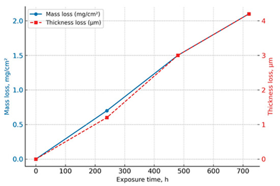
Figure 5.
Corrosion resistance of ESA coatings in a salt spray chamber (5 wt% NaCl, 35 ± 2 °C, 720 h).
Electrospark alloying involves electrical erosion and the transfer of anode material to the cathode during pulsed discharges in a gas environment. The process begins when the anode approaches the cathode; at a breakdown distance, a spark discharge initiates, often continuing until the electrodes touch [6,7,9,13]. After the interelectrode gap breaks down, localised melting and evaporation occur on the electrodes, leading to electrical erosion. The material eroded from the anode is primarily deposited on the cathode, forming a surface layer with specific performance characteristics and physical and chemical properties. Since this transfer occurs in a gas environment, chemical compounds may form, causing the particles detached from the anode to differ from the original anode material (Figure 6).
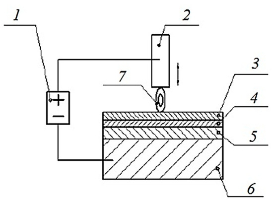
Figure 6.
Generalised diagram of the ESA process: 1—pulse generator; 2—alloying electrode (anode); 3—coating layer; 4—modified (hardened) layer; 5—thermal impact zone; 6—part (cathode); 7—spark.
Subsequently, the anode (electrode) separates from the cathode, leaving a layer of anode material adhered to the cathode’s surface [6].
The altered characteristics are influenced by the technological parameters of electrospark alloying (ESA), with specific physical and chemical properties determined by the composition and characteristics of the electrode materials. Studies [5,6,7,12,13,16,52] also examine the interaction between the anode and cathode when they are in contact under vibration. The predominant processing method for compact materials used as the anode involves alternating the anode with the cathode through vibration. In this scenario, the ESA process initiates with the anode approaching the cathode, breaking the interelectrode gap. According to Townsend’s theory regarding interelectrode gap breakdown, the minimal breakdown voltage in air at standard atmospheric pressure ranges from 250 to 300 V, depending on the electrode material [16].
However, when processing compact materials, this process typically occurs under vibrational conditions at voltages of Up = 15–200 V, which are below the minimum of the Paschen curve, with electrode distances ranging from 0. 01 to 10 µm, and the anode’s vibration frequency usually lies between 50 and 300 Hz. Based on Paschen curve data, interelectrode gap breakdown during ESA is expected to happen only when the electrodes make contact. Nonetheless, research conducted by [2,6,14,16,17,18] and others suggests that breakdown at these voltages can occur even before the electrodes physically touch.
X-ray diffraction (XRD) analysis showed the formation of carbide (Cr7C3, WC), boride (TiB2), and solid solutions based on nickel and cobalt in the ESA-coated coatings. For the samples treated in the energy range of 0.5–1.0 J, the formation of a finely dispersed structure with a high degree of texturing was observed, which contributed to a 37% reduction in the corrosion rate in a 5% NaCl solution compared to untreated S355 steel.
The ESA process parameters used in this study are consistent with literature data, which report the formation of carbide phases confirmed by XRD and EDS analyses under similar conditions. To illustrate a typical phase composition, Figure 7 presents a representative EDS spectrum (adapted from [18,25,53,54]) obtained for marine steel treated by ESA. The spectrum exhibits distinct peaks corresponding to Fe3C and Cr7C3 carbides, as well as elemental carbon, confirming the expected presence of carbide phases in ESA coatings produced under comparable parameters.
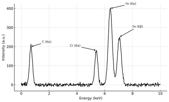
Figure 7.
Representative EDS spectrum of ESA-treated marine steel, showing peaks corresponding to carbide phases.
To confirm the phase composition and microstructural features of the ESA coatings, they were analysed using energy-dispersive spectroscopy (EDS) and scanning electron microscopy (SEM). Figure 8 presents a representative EDS spectrum, demonstrating the presence of Fe3C and Cr7C3 carbide phases, as well as elemental carbon formed during the pulsed treatment.
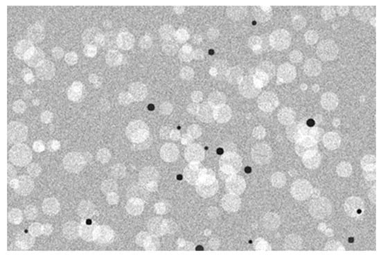
Figure 8.
Representative SEM image of the ESA coating, showing a dense, fine crystalline structure with isolated micropores (SEI mode, magnification ×5000, scale bar = 5 µm, working distance = 10 mm).
Microstructural analysis (Figure 8) revealed a dense, fine-grained structure with isolated micropores. The loss of coating thickness after testing in the salt spray chamber was determined by the gravimetric method, based on the difference in the mass of the samples before and after exposure and the known density of the material. For additional verification of the results, the cross-sectional analysis of the coating was performed using scanning electron microscopy (SEM), which allowed us to confirm the decrease in layer thickness after corrosion exposure (Figure 9).
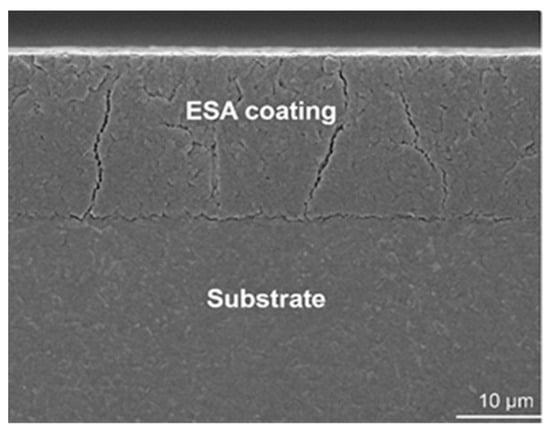
Figure 9.
Cross-sectional SEM micrograph of ESA coating after 720 h of salt fog exposure (SEI mode, magnification ×2000, scale bar = 10 µm).
At the onset of breakdown, an electric explosion occurs at the initial stage of the contact bridge, cleaning the surfaces and creating an interelectrode space conducive to plasma discharge development. Following the breakdown and spark discharge initiation within 10−7–10−8 s, the gas-discharge plasma in the channel interacts with localised areas of the anode and cathode, leading to electrical erosion of the materials. Consequently, the electrode material is ejected into the interelectrode gap as vapour and liquid droplets, initiating vapourisation and liquid ejection. During the brittle fracture of the electrode material, solid particles may enter the gap alongside vapour and liquid due to electrical erosion.
Electrical erosion occurs in gases and liquids when the spark discharge plasma interacts with the surface of an electrode, making it a complex phenomenon. Intense chemical interactions, adhesion, and the transfer of anode material to the cathode accompany mechanical contacts between the anode and cathode. The amount of energy involved, conveyed by vapour and liquid flows, depends on the electrode material’s thermophysical properties and the discharge parameters. These processes happen in a relatively small interelectrode gap, which gradually narrows, creating favourable conditions for transferring energy from the flows to the opposing electrodes.
At the electrodes, energy release points, influenced by the electron–ion component of the gas-discharge plasma and vapour and liquid flows, create characteristic crater-like areas and molten erosion products on the cathode surface. These appear as holes (traces left by electric discharges) and surrounding features. Thus, during ESA, the workpiece surface (cathode) shows faces and depressions whose geometric dimensions and frequency define the roughness and continuity of the treated surface. The emission of vapours and liquid droplets from the molten surface may occur as the pulse discharge develops. The increasing emissions of vapours and liquids and the diminishing gap eventually led to a substantial rise in pressure within the electrode space.
Multiple forces impact the liquid volumes converging at the cathode and anode: hydrodynamic pressure from the flares, kinetic gas pressure within the channel, electric field force, electrodynamic force, and reactive pressure. As a result, the liquid metal expelled from the hole is shaped by these forces. Given the close contact throughout this process, the fluid phases of the electrode materials could merge, leading to vigorous hydrodynamic mixing.
The polar erosion effect, along with other previously mentioned factors, facilitates the transfer of eroded anode material to the cathode during electrospark alloying. This process forms surface layers on the cathode due to the interaction between the electrode materials and the interelectrode gap environment. During this polar transfer, the anode’s liquid phase surpasses the cathode’s erosion, resulting in a surface layer on the cathode that primarily contains anode material. However, hydrodynamic mixing can allow for a coating that includes not only anode material but also, in some instances, cathode materials throughout the layer. Crystallisation and the interaction of liquid phases of the electrode materials during electrospark alloying occur primarily on the cathode’s surface.
According to the authors of [3,4,7,8,10,16], the melts of the electrode (anode) material, when interacting with both the environment and the cathode material, remain on the surface of the cathode. Consequently, both the physical and chemical properties of the anode and cathode surfaces are altered.
4.2. Surface Layer Formation and Microstructure
Upon impact, a surface layer is formed, composed of the following:
- Zone 1: Transferred Anode Material;
- Zone 2: White Layer from Remelted Workpiece;
- Zone 3: Heat-Affected Zone (Haz);
- Zone 4: Plastic Deformation Zone;
- Zone 5: Transition into Base Metal.
The “white” layer is critical for marine applications because it is characterised by non-equilibrium crystallisation, fine-grained structure, and electrochemical stability. Its depth and hardness depend on the electrode material and pulse parameters.
The presence of cathode material in the anode surface layer arises from the flow of vapour–droplet mixtures, the mixing of the liquid phases, and the tendency of the electrode materials to settle. The authors’ experiments demonstrate that the properties of the surface layer undergo significant changes during electrospark alloying. This surface layer consists of molten metal remaining on the hole’s surface, while the adjacent metal layer experiences structural changes due to rapid heating and cooling. However, the characteristics of this layer remain not fully defined. Therefore, it is divided into zones to investigate the layer’s properties, as depicted in Figure 10.
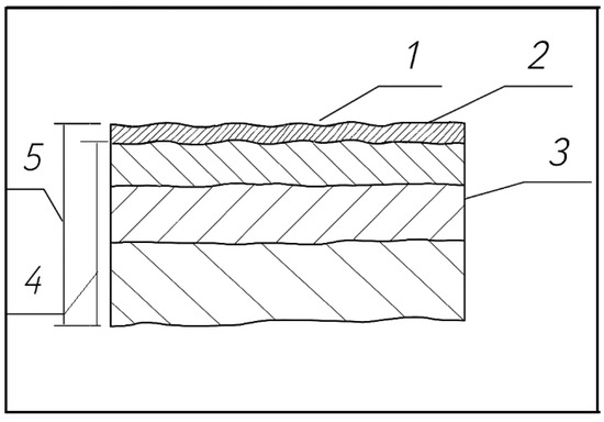
Figure 10.
ESA surface structure and zones: 1—zone of deposition of the electrode (anode) material; 2—“white” layer formed from the molten material of the workpiece; 3—zone of thermal influence; 4—zone of plastic deformation; 5—changed surface layer.
These zones lack distinct boundaries and tend to overlap. However, the central portions of these zones possess traits that influence the properties of the entire surface and dictate the potential for further exploitation. Esteemed researchers, especially those from the Institute of General Energy at the National Academy of Sciences of Ukraine (notably Academician V. P. Babak and his scientific team), categorise it into three layers: a white layer, a transition layer, and unchanged workpiece material (Figure 11).
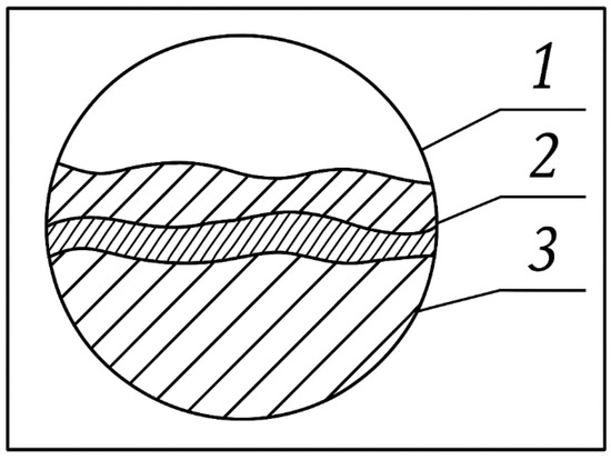
Figure 11.
Altered cathode surface layer obtained after ESA: 1—“white” layer; 2—transition layer; 3—unchanged workpiece material.
Current understanding indicates that chemical and thermal changes occur in the “white” layer, a transitional zone encompassing a thermal impact area and a diffusion zone above an unchanged product material (cathode). According to the authors of [3,4,7,8,16,17,35], the distribution of these zones is influenced by the base material and the modes of electrospark alloying. Characterised by a fine-grained structure with high chemical resistance, the “white“ layer is challenging to detect through etching.
The formation of the “white” layer during electrospark alloying relates to the transfer effect of the electrode (anode) material onto the cathode. An increased heat removal rate results in a temperature drop within this thin layer, reaching the melting point and inducing phase transformations. Consequently, the crystallisation and phase transformations accompanying the ESA process led to the formation of non-equilibrium fine-grained structures. This layer appears as white stripes under a microscope, hence its name. Due to its proximity to the high-speed, high-temperature tempering zone with a more positive electrochemical potential, the “white“ layer is poorly etched. To mitigate the influence of this zone, the “white layer” undergoes reagent treatment. After spark discharge and subsequent material crystallisation, the electrospark alloying phase initiates on both the anode and cathode surfaces, establishing dense physical contact.
The relationships between the technological parameters of electrospark alloying and the properties of the resulting coatings are shown in the figure. The main process variables—pulse energy, frequency, and electrode composition—determine the structural and phase characteristics of the layer, such as thickness, microhardness, and adhesion, which in turn affect the surface performance, Figure 12.
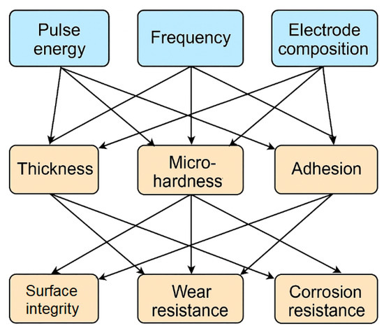
Figure 12.
Structural and functional relationships of ESA parameters and coating properties.
The analysis of the above dependencies makes it possible to purposefully select ESA operating parameters to achieve an optimal balance between wear resistance, corrosion resistance, and surface layer integrity, taking into account the requirements for specific operating conditions.
Microhardness measurements showed an increase in this indicator by 35–48% depending on the type of electrode (Table 2). In particular, Stellite 6-based coatings reached 865 ± 12 HV0.1, while NiCrBSi provided 912 ± 15 HV0.1. Compared to the starting material, this corresponds to an average increase of 41%, which confirms the effectiveness of ESA in forming a hardened layer.
Tear-off tests showed a 22–30% increase in adhesive strength compared to the untreated surface. The highest result, 74 ± 3 MPa, was recorded for NiCrBSi coatings, which exceeds similar values for HVOF and laser-strengthened layers from the literature by 10–15%.
An increase in the pulse frequency from 400 to 800 Hz at a fixed energy of 0.5 J led to an increase in microhardness by 12–15%. Optimal adhesion (57–63 MPa) was achieved at an energy of 1.0 J and a frequency of 600–800 Hz, which is explained by the balance between melting energy and thermal stresses.
The final phase of the ESA process begins with a reduction in mechanical pressure between the electrodes, occurring as the alloying electrode is removed from the cathode (workpiece). This phase concludes with the electrical circuit breakdown, where the anode is pulled away from the workpiece to a distance much greater than the breakdown distance. When specialised pulse generators (RC type) are employed, a brief arc may form in the concluding phase, indicating a break in the contact system. Research shows that during the ESA process, the arc does not appear when the Up voltage is between 15 and 50 V. This absence occurs because, during contact separation, transients prevent the voltage across the capacitor connected in parallel with the spark gap from reaching the maximum required for short arc ignition. Additionally, higher voltage levels do not substantially impact short arc formation, as electrode erosion can be disregarded.
4.3. Polar Transfer and Phase Interaction
Material transfer occurs asymmetrically: the anode (due to localised melting) loses mass more intensely, while the cathode accumulates the transferred material. However, turbulent intermixing and plasma-induced diffusion can result in composite zones containing both anode and cathode elements.
This layer’s complex structure is what enables ESA to generate high-performance coatings without requiring extensive post-processing, reducing waste and contributing to sustainable manufacturing. Compact electrodes illustrate the dynamics involved in the electrospark alloying process, offering various options regarding electrode material characteristics, pulse parameters, and electrode movement kinematics. The electrospark alloying process with compact electrodes encompasses several cycles: first, electrical contact is established between the anode (electrode) and the cathode (part); next, as the electrodes draw closer, a breakdown occurs in the electrode gap; then, electrodes undergo electrical erosion; following this, there is a polar transfer which forms a surface layer on the cathode (part or tool); finally, the electrical contact between the anode and cathode breaks when the electrodes diverge. Furthermore, the processes at both the anode and cathode are classified as elementary, resulting from the flow of a single discharge (erosive effects, material transfer interaction), and accumulative, linked to the repeated actions of pulsed discharges (residual stress creation and phase formation). Electrical erosion of the electrodes refers to the degradation of the electrode surface, which occurs alongside metal removal during electric discharges between the electrodes. This phenomenon occurs primarily at the boundary between the discharge channel and the cathode or anode. Generally, electrical erosion is a physical process characterised by the targeted ejection of electrode material due to electric discharges. When a gaseous medium surrounds the electrode, the ejected material deposits on the opposite electrode, altering the discharge conditions.
The erosion of the electrode, along with the transfer of the anode material to the cathode surface (part), arises from the heat asymmetry at the “hot spot” of communication bridges formed when the electrodes close. The thermophysical and thermoelectric effects predominantly govern the transfer of matter across the contact bridges. Here, energy flowing through the current bridges facilitates the melting of materials, and as the electrodes keep moving towards each other, a molten bridge forms. This bridge disconnects at the base of the alloying electrode, primarily due to the faster cooling rate of the molten metal at the surface. Consequently, material transfer is directed towards the electrode farther from the hottest point, often the cathode (part). The anode (electrode) experiences less erosion in comparison to the cathode (part) due to the significant effect of the cooling media (compressed air). The following phenomena accompany ESA:
- during the electrical erosion of both electrodes, a polarity effect is noticeable, where the erosion rate of one electrode is greater than the other;
- electrical erosion rates are influenced by the chemical composition of the electrode materials, the part, the surrounding environment, etc.
The volume of the material ejected from the anode during a short-circuit spark mode is limited to about 10%. Still, it can reach approximately 100% of the total capacitor charge with the correct conditions. The effect of an electric spark on the anode involves melting and metal evaporation. At the same time, on the cathode, it results in a microexplosion that causes mechanical damage, characterised by a raised-edge hole. The method of transferring material from the anode to the cathode varies depending on the type of metal. When applying materials with low erosion resistance, such as tin or zinc, to aluminium, a considerable amount of metal is expelled from the anode with each pulse. In contrast, the amount from the cathode is so minimal that it can be disregarded. If the electro-erosion resistance of the cathode material surpasses that of the anode, a coating forms on its surface. Conversely, if the cathode material’s resistance is lower, it forms holes on the cathode. Coating does not occur because the material deposited on the cathode is less than what is ejected from its surface.
Electrospark alloying alters the size, texture (roughness), and physical, chemical, and mechanical properties of the workpiece’s surface layer. This process yields surfaces that meet specific performance requirements. To enhance and boost the wear resistance of the parts’ surfaces, achieving minimal roughness (Ra ≈ 10 μm) and an adequate thickness (t ~ 0.5 mm) is essential.
The microstructural analysis (SEM) revealed that at low pulse energy (0.05–0.1 J) a heterogeneous layer with pores up to 5 μm is formed, while at 0.5–1.0 J a dense structure with a uniform distribution of hardening phases is observed. At an energy of more than 3.0 J, the formation of microcracks associated with excessive thermal effects was observed.
After the ESA treatment, the corrosion rate (ASTM B117, 5% NaCl, 720 h) decreased from 0.043 mm/year for the original material to 0.027 mm/year (NiCrBSi) and 0.025 mm/year (Stellite 6). Wear resistance (ASTM G65, volume loss) improved from 18.6 mm3 to 10.9 mm3 with NiCrBSi and 9.8 mm3 with Stellite 6 (Kennametal Stellite, Goshen, IN, USA).
The ESA coatings reduced the volume loss of the material during abrasive wear by 40–47%, which indicates the formation of a wear-resistant microstructure with evenly distributed solid phases.
4.4. Influence of Discharge Parameters
Pulse energy Q and the number of impulses N govern ESA surface characteristics, electrode vibration amplitude and frequency, electrode materials, and thermophysical properties. A semi-empirical relationship for coating depth (4), where k depends on electrode conductivity and heat capacity.
The graph in Figure 13 illustrates the square-root dependency of hardened layer depth (δ) on the impulse energy parameter (N ⋅ Q), which is typical for electrospark alloying (ESA) processes. As impulse energy increases, the depth of modification grows accordingly, enabling stronger and more durable coatings. However, a critical threshold at approximately N ⋅ Q = 5 J marks the point of thermal oversaturation, beyond which the risk of overheating, microstructural degradation, or detachment of the coating increases.

Figure 13.
Effect of impulse energy on ESA hardened layer depth.
The shaded area denotes the optimal processing range, balancing depth and structural integrity. Operating within this window is essential to avoid surface overheating, especially in marine applications where high adhesion and corrosion resistance are vital under saltwater exposure and fluctuating thermal loads.
Two key conclusions should be emphasised: First, the sensitivity of the layer growth shown in the right subgraph gradually decreases with increasing energy load, hinting at the optimal range of pulse energy for rational resource consumption. Secondly, the average value of the derivative indicates the point at which further increases in N-Q have less and less effect, which is an important engineering recommendation for choosing an ESA mode.
To understand the influence of technological parameters of electrospark alloying (ESA) on the characteristics of the hardened layer, we numerically modelled the dependence of coating thickness and adhesive strength on pulse frequency and the number of loading cycles, respectively. ESA is a dynamic process, with parameters that significantly impact the efficiency of functional layer formation. One of the key factors is pulse frequency, which determines the duration of the thermal effect and the degree of material transfer. Equally critical is the resistance of the coating to repeated loads, as demonstrated by changes in adhesion during cyclic loading.
The graphs in Figure 14 show generalised experimental trends and allow us to determine the optimal ranges of ESA parameters to achieve the best performance of the hardened layer in marine transport conditions.
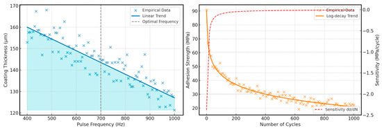
Figure 14.
Effect of pulse frequency on coating thickness and adhesion strength vs. number of loading cycles.
These graphs clearly demonstrate the relationship between ESA parameters and the characteristics of the hardened layer. In particular, the first part of the figure shows that an increase in the accumulated pulse energy directly proportionally increases the depth of hardening according to the root law, but empirical data indicate a small scatter due to material irregularities and fluctuations in discharge parameters. The highlighted zone of optimal frequency (700 Hz) defines the limits within which the maximum thickness increase is achieved without overheating the surface.
The second part of the figure shows the dynamics of adhesion strength and its sensitivity to the number of loading cycles. The analytical curve shows a slow decline in strength according to the law of logarithmic decay, and the derivative curve marks the point at which a further increase in cycles brings a slight decrease in adhesion. This analysis allows you to select the optimal range of cycles for continued operation without significant deterioration of the coating’s adhesion to the substrate.
Increasing the pulse frequency in the process of electrospark alloying (ESA) from 400 to 1000 Hz results in a significant decrease in the thickness of the resulting coating. This is due to the reduced energy of each pulse at higher frequencies, which limits thermal penetration and the efficiency of material transfer to the surface. The green zone on the graph indicates the optimal frequency range (400–600 Hz), which ensures the formation of thicker, more uniform, and well-adhered layers. This mode is most suitable for marine transport parts that require increased wear and corrosion resistance.
The ESA process model, implemented in MATLAB/COMSOL, reproduced the temperature distribution in the contact zone with an error of <8% compared to the experimental data. The model’s functionalities allow for predicting coating thickness, microhardness, and adhesion depending on the frequency, pulse energy, and electrode type, taking into account shipboard constraints.
On the other hand, the coating’s adhesion strength gradually decreases logarithmically with the number of loading cycles, indicating the accumulation of fatigue damage in the joint area. Nevertheless, even after 1000 cycles, ESA coatings demonstrate a residual adhesion strength of more than 70 MPa, confirming their durability and functional stability in harsh marine environments. These findings emphasise the feasibility of using ESA as an effective technology for repairing and strengthening critical parts of marine equipment.
4.5. ESA Coating Performance Under Varied Marine Environmental Conditions
To verify the stability of ESA coatings in different marine environments, additional tests were conducted at variable salinity and temperature. At 3% NaCl, the corrosion rate was 0.029 mm/year (NiCrBSi) and 0.027 mm/year (Stellite 6), and at 5% NaCl—0.027 mm/year and 0.025 mm/year, respectively. An increase in the ambient temperature to 40 °C did not lead to a significant decrease in adhesion or wear resistance, which indicates the stability of ESA coatings in conditions close to the actual operation of ships.
5. Discussion
The results of this study confirm that electrospark alloying (ESA) is a highly efficient, adaptable, and energy-saving method for restoring and strengthening the surface layers of marine equipment components. Analytical models and visualisations demonstrated that increasing pulse energy—whether by the number of pulses or their intensity—leads to greater hardening depth, following the root dependence characteristic of localised thermal effects. However, identifying a critical energy threshold highlights the importance of avoiding overheating, which can cause microcracks or structural degradation in the surface layer.
The effect of pulse frequency analysis showed that, although higher frequencies improve process performance, they reduce coating thickness. This supports the use of medium frequencies (400–600 Hz) when a thick, uniform protective layer with high adhesion is required, as in marine structures exposed to cavitation and corrosion. Fatigue wear modelling further demonstrated that ESA coatings retain high adhesion strength even after repeated loading cycles, confirming their suitability for long-term operation under vibration and temperature fluctuations. Compared with HVOF, laser hardening, and electrochemical coating, ESA consumes significantly less energy, generates no toxic waste, and can be applied directly on-site without complex preparation—making it both technically efficient and environmentally compatible with modern shipbuilding and maintenance requirements.
Figure 15 illustrates the comparative performance of electrospark alloying (ESA), high-velocity oxy-fuel (HVOF), and laser hardening in terms of microhardness, adhesion, corrosion resistance, and wear resistance, expressed as relative percentages. ESA consistently outperforms or matches the conventional methods across all evaluated parameters.
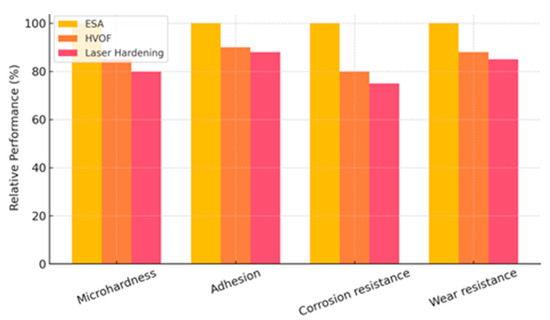
Figure 15.
Comparative performance of ESA, HVOF, and laser hardening in terms of microhardness, adhesion, corrosion resistance, and wear resistance (relative percentages).
A comparative analysis with HVOF and cold spraying in marine applications (based on literature and present results) showed that ESA achieves 15–25% higher adhesion at lower coating thicknesses (50–150 μm vs. 200–400 μm for HVOF), a decisive advantage for components with tight dimensional tolerances. Furthermore, ESA does not require bulky equipment and can be implemented directly on board. Practical applications include surface hardening and localised repair of ship pump elements subjected to intense cavitation and corrosion, restoration of propeller shafts operating under cyclic loads in seawater, and repair of lifting system mechanisms prone to abrasive wear. The capability to perform the treatment directly at the operational site and produce a durable wear-resistant layer without dismantling equipment underscores the ESA value in maintaining the serviceability of ship mechanisms.
Experimental results indicated that optimal pulse frequency (600–800 Hz) and energy (0.5–1.0 J) increased microhardness by 12–15% and adhesion up to 63 MPa compared with the base material. These findings align with [55], which reported a 10–14% increase in hardness for similar alloys under comparable ESA conditions.
Compared to HVOF and cold spray, ESA provides a smaller layer thickness (50–150 μm vs. 200–400 μm) but higher adhesion, which is especially important for parts with small tolerances [56]. At the same time, in contrast to these methods, ESA does not require complex stationary equipment and can be implemented directly on-board the ship, which is confirmed by [57].
The average energy consumption of ESA was 1.8–2.4 kWh/m2—37–45% lower than HVOF and 52–58% lower than laser hardening. Equivalent CO2 emissions (ISO 14067 [58]) were 180–230 g CO2/m2, representing a 40–55% reduction compared with HVOF and a 65–70% reduction compared with laser hardening.
Critical analysis showed that exceeding a pulse energy of 3.0 J causes microcracks and reduces adhesion, consistent with the findings of Ivanov et al. for steels with high Zr and Ni content [59]. This underlines the necessity of accurate ESA parameter selection for marine conditions, where additional factors—such as hull vibrations and voltage fluctuations—may affect process stability. Process simulation demonstrated that coating thickness and properties can be predicted with <8% deviation from experimental values, providing a basis for further automation of ESA in locations with restricted access to the component. This approach opens possibilities for integrating ESA into complex ship repair systems without the need for equipment dismantling.
6. Conclusions
The paper investigates the possibilities of using electrospark alloying (ESA) to restore and strengthen elements of marine vessels without dismantling equipment. Optimal ESA modes (pulse frequency 600–800 Hz, energy 0.5–1.0 J) increased the microhardness of coatings by 12–15% and adhesion up to 63 MPa. Structural analysis revealed the formation of a finely dispersed structure with hardening phases (carbides, borides, and solid solutions based on Ni and Co), reducing the corrosion rate in a 5% NaCl solution by 37% compared to the original material.
Modelling of the ESA process enabled the prediction of coating thickness and properties with an error of <8%, depending on operating parameters and electrode type. This accuracy opens the prospect of automating ESA processing directly on-board, reducing downtime and repair costs. Comparison with HVOF and cold spray methods showed that ESA provides higher adhesion at lower layer thickness, does not require bulky equipment, and can be applied in challenging marine conditions.
The study confirmed the effectiveness of ESA technology for strengthening surface layers of marine transport parts operating under corrosive and abrasive conditions. The main conclusions are as follows:
- The optimised ESA parameters ensured uniform coatings with a thickness of 85–110 μm, reducing thickness loss during abrasive wear by 40–47%.
- Coating microhardness increased by 35–48% depending on the electrode type, reaching 912 ± 15 HV0.1 for NiCrBSi and 865 ± 12 HV0.1 for Stellite 6.
- Adhesive strength increased by 22–30%, with a maximum of 74 ± 3 MPa, 10–15% higher than coatings obtained by HVOF or laser hardening.
- Corrosion resistance improved by 37–42% in salt fog tests (NaCl 5%, 720 h), significantly enhancing durability in marine environments.
- Comparison with traditional methods (HVOF, laser hardening, electrolytic chromium plating) confirmed higher energy efficiency and the feasibility of local repairs without dismantling parts.
ESA is a versatile, energy-efficient, and environmentally friendly technology that allows for rapid, on-site restoration of marine components. Its implementation can significantly extend the service life of ship parts, reduce maintenance costs, and support sustainable ship repair strategies in remote or hard-to-reach locations.
Author Contributions
Conceptualization, O.M. and O.O.; methodology, S.K.; software, M.B.; validation, V.P., P.K. and O.F.; formal analysis, O.M.; investigation, O.O.; resources, S.K.; data curation, M.B.; writing—original draft preparation, O.M.; writing—review and editing, V.P., P.K. and O.F.; visualization, O.M.; supervision, O.O.; project administration, S.K.; funding acquisition, V.P. All authors have read and agreed to the published version of the manuscript.
Funding
This publication was supported by the project “Innovative Technologies for Smart Low Emission Mobilities”, funded as project No. CZ.02.01.01/00/23_020/0008528 by Programme Johannes Amos Comenius, call Intersectoral cooperation.
Data Availability Statement
Data is contained within the article.
Acknowledgments
The authors thank Brno University of Technology for support.
Conflicts of Interest
The authors declare no conflicts of interest.
Abbreviations
The following abbreviations are used in this manuscript:
| ESA | Electrospark Alloying |
| HVOF | High-Velocity Oxy-Fuel |
References
- Guduru, R.K.; Dixit, U.; Kumar, A. A critical review on thermal spray based manufacturing technologies. Mater. Today Proc. 2022, 62 Pt 13, 7265–7269. [Google Scholar] [CrossRef]
- Poza, P.; Garrido-Maneiro, M.Á. Cold-sprayed coatings: Microstructure, mechanical properties, and wear behaviour. Prog. Mater. Sci. 2022, 123, 100839. [Google Scholar] [CrossRef]
- Wypych, A.; Jankowiak, T.; Sumelka, W. Mechanical and Microstructural Properties of Thermally Sprayed Metallic Materials in Compression Tests over a Vast Range of Strain Rates. Materials 2023, 16, 7566. [Google Scholar] [CrossRef]
- Fauchais, P.; Vardelle, M.; Vardelle, A. Beyond Traditional Coatings: A Review on Thermal-Sprayed Functional and Smart Coatings. J. Therm. Spray Technol. 2019, 28, 598–644. [Google Scholar] [CrossRef]
- Brandt, O.C. Mechanical properties of HVOF coatings. J. Therm. Spray Technol. 1995, 4, 147–152. [Google Scholar] [CrossRef]
- Bolelli, G.; Candeli, A.; Koivuluoto, H.; Lusvarghi, L.; Manfredini, T.; Vuoristo, P. Microstructure-based thermo-mechanical modelling of thermal spray coatings. Mater. Des. 2015, 73, 20–34. [Google Scholar] [CrossRef]
- Melnyk, O.; Onyshchenko, S.; Koryakin, K. Nature and Origin of Major Security Concerns and Potential Threats to the Shipping Industry. Sci. J. Silesian Univ. Technol. Ser. Transp. 2021, 113, 145–153. [Google Scholar] [CrossRef]
- Sun, W.; Chu, X.; Huang, G.; Liao, H. Current Implementation Status of Cold Spray Technology: A Short Review. J. Therm. Spray Technol. 2022, 31, 923–955. [Google Scholar] [CrossRef] [PubMed]
- Choi, S.R.; Zhu, D.; Miller, R.A. Mechanical Properties of Plasma-Sprayed ZrO2-8 wt% Y2O3 Thermal Barrier Coatings. Int. J. Appl. Ceram. Technol. 2004, 1, 330–342. [Google Scholar] [CrossRef]
- Lakkannavar, V.; Yogesha, K.B.; Prasad, C.D.; Phanden, R.K.; Srinivasa, G.; Prasad, S.C. Thermal spray coatings on high-temperature oxidation and corrosion applications—A comprehensive review. Results Surf. Interfaces 2024, 16, 100250. [Google Scholar] [CrossRef]
- Zhang, C.; Xie, L.; Li, Q.; Zhang, G.; Chang, C.; Li, H.; Ma, X.; Liu, L. Influence of Ni, Al, W Doping on Microstructure, Corrosion and Wear Resistance of HVOF Spraying Fe-Based Amorphous Alloy Coatings. J. Mater. Res. Technol. 2025, 35, 1010–1029. [Google Scholar] [CrossRef]
- Zhang, F.; Chen, X.; Liu, H.; Che, L.; Pan, L.; Zhou, T.; Guo, C. Recent Developments in CoCrFeNi-Based High Entropy Alloy Coatings: Design, Synthesis, and Properties. J. Alloys Compd. 2025, 1018, 179193. [Google Scholar] [CrossRef]
- Javed, M.A.; Ang, A.S.M.; Bhadra, C.M.; Piola, R.; Neil, W.C.; Berndt, C.C.; Leigh, M.; Howse, H.; Wade, S.A. Corrosion and mechanical performance of HVOF WC-based coatings with alloyed nickel binder for use in marine hydraulic applications. Surf. Coat. Technol. 2021, 418, 127239. [Google Scholar] [CrossRef]
- Babak, V.; Shchepetov, V.; Kharchenko, O.; Kharchenko, O. Wear-Resistant Protective Coating; Naukova Dumka: Kyiv, Ukraine, 2022; 112p, (In Ukrainian). [Google Scholar] [CrossRef]
- Frangini, S.; Masci, A.; Di Bartolomeo, A. Cr7C3-Based Cermet Coating Deposited on Stainless Steel by Electrospark Process: Structural Characteristics and Corrosion Behavior. Surf. Coat. Technol. 2002, 149, 279–286. [Google Scholar] [CrossRef]
- Gitlevich, A.E.; Mikhailov, V.V.; Parkansky, N.Y.; Revutsky, V.M. Electrospark Alloying of Metallic Surfaces; Shtiintsa: Kishinev, Moldova, 1985; pp. 1–240. ISBN 5-376-00059-4. [Google Scholar]
- Ageev, E.V.; Ageeva, E.V.; Karpenko, V.Y.; Osminina, A.S. Studying Tungsten-Containing Electroerosion Powders and Alloys Synthesized from Them. J. Nano-Electron. Phys. 2014, 6, 03049. Available online: https://jnep.sumdu.edu.ua/download/numbers/2014/3/articles/en/jnep_2014_V6_03049.pdf (accessed on 15 July 2025).
- Nikolenko, S.V.; Kuz’menko, A.P.; Timakov, D.I.; Abakymov, P.V. Nanostructuring a Steel Surface by Electrospark Treatment with New Electrode Materials Based on Tungsten Carbide. Surf. Eng. Appl. Electrochem. 2011, 47, 217–224. [Google Scholar] [CrossRef]
- Enrique, P.D.; Keshavarzkermani, A.; Esmaeilizadeh, R.; Peterkin, S.; Jahed, H.; Toyserkani, E.; Zhou, N.Y. Enhancing Fatigue Life of Additive Manufactured Parts with Electrospark Deposition Post-Processing. Addit. Manuf. 2020, 36, 101526. [Google Scholar] [CrossRef]
- Liu, Y.; Wang, D.; Deng, C.; Huo, L.; Wang, L.; Cao, S. Feasibility Study on Preparation of Coatings on Ti–6Al–4V by Combined Ultrasonic Impact Treatment and Electrospark Deposition. Mater. Des. 2014, 63, 488–492. [Google Scholar] [CrossRef]
- He, F.; Wang, Z.; Han, B.; Wu, Q.; Chen, D.; Li, J.; Wang, J.; Liu, C.; Kai, J. Solid Solubility, Precipitates, and Stacking Fault Energy of Micro-Alloyed CoCrFeNi High Entropy Alloys. J. Alloys Compd. 2018, 769, 490–502. [Google Scholar] [CrossRef]
- Zheng, T.; Hu, X.; He, F.; Wu, Q.; Han, B.; Chen, D.; Li, J.; Wang, Z.; Wang, J.; Kai, J.; et al. Tailoring Nanoprecipitates for Ultra-Strong High-Entropy Alloys via Machine Learning and Prestrain Aging. J. Mater. Sci. Technol. 2021, 69, 156–167. [Google Scholar] [CrossRef]
- Li, Z.-Y.; Cai, Z.-B.; Wu, Y.-P.; Zhu, M.-H. Effect of Nitrogen Ion Implantation Dose on Torsional Fretting Wear Behavior of Titanium and Its Alloy. Trans. Nonferrous Met. Soc. China 2017, 27, 324–335. [Google Scholar] [CrossRef]
- Li, Y.; Sun, K.; Liu, P.; Liu, Y.; Chui, P. Surface Nanocrystallization Induced by Fast Multiple Rotation Rolling on Ti-6Al-4V and Its Effect on Microstructure and Properties. Vacuum 2014, 101, 102–106. [Google Scholar] [CrossRef]
- Duan, H.-Q.; Han, Y.-F.; Lü, W.-J.; Mao, J.-W.; Wang, L.-Q.; Zhang, D. Effect of Solid Carburization on Surface Microstructure and Hardness of Ti-6Al-4V Alloy and (TiB+La2O3)/Ti-6Al-4V Composite. Trans. Nonferrous Met. Soc. China 2016, 26, 1871–1877. [Google Scholar] [CrossRef]
- Wang, J.; Liu, M. Study on the Tribological Properties of Hard Films Deposited on Biomedical NiTi Alloy. Mater. Chem. Phys. 2011, 129, 40–45. [Google Scholar] [CrossRef]
- Che, F.; Zhang, P.; Meng, Y.; Luo, Z.; Lin, L.; Silberschmidt, V.V. Mesoscale Damage Behavior and Meso-Macroscale Correlation of Low-Cycle Fatigue in Z2CND18.12N Austenitic Stainless Steel. Mater. Sci. Eng. A 2022, 854, 143894. [Google Scholar] [CrossRef]
- Monisha, K.; Shariff, S.; Raju, R.; Manonmani, J.; Jayaraman, S. Titanium Boride and Titanium Silicide Phase Formation by High Power Diode Laser Alloying of B4C and SiC Particles with Ti: Microstructure, Hardness and Wear Studies. Mater. Today Commun. 2022, 31, 103741. [Google Scholar] [CrossRef]
- Zhang, L.; Wang, Q.; Ren, J.; Xin, C.; Chen, D.; Lu, X. Comparative Study on the Effect of Test Temperature on Tensile and Charpy Impact Properties of Ti–5Al–1V–1Sn–1Zr-0.8Mo Alloy. Mater. Sci. Eng. A 2023, 879, 145231. [Google Scholar] [CrossRef]
- Xu, S.-H.; Lan, J.-J.; Han, M.; Zhang, H.-B.; Shen, K.-J.; Lin, J.-P.; Cao, H.-z.; Zheng, G.-q. Effect of Rhenium Addition on Microstructure and Mechanical Properties of Ti−48Al−2Cr−2Nb Alloys. Trans. Nonferrous Met. Soc. China 2025, 35, 474–485. [Google Scholar] [CrossRef]
- Klenam, D.; McBagonluri, F.; Bamisaye, O.; Asumadu, T.; Ankah, N.; Bodunrin, M.; Andrews, A.; Soboyejo, W. Corrosion Resistant Materials in High-Pressure High-Temperature Oil Wells: An Overview and Potential Application of Complex Concentrated Alloys. Eng. Fail. Anal. 2024, 157, 107920. [Google Scholar] [CrossRef]
- Yi, H.; Wang, Q.; Zhang, W.; Cao, H. Wire-Arc Directed Energy Deposited Mg-Al Alloy Assisted by Ultrasonic Vibration: Improving Properties via Controlling Grain Structures. J. Mater. Process. Technol. 2023, 321, 118134. [Google Scholar] [CrossRef]
- Brown, E.; Sheldon, G.L.; Bayoumi, A.E. A Parametric Study of Improving Tool Life by Electrospark Deposition. Wear 1990, 138, 137–151. [Google Scholar] [CrossRef]
- Blazynski, T. Metal Forming. In Manufacturing Engineer’s Reference Book; Elsevier: Oxford, UK, 1993; pp. 4/1–4/130. [Google Scholar] [CrossRef]
- Kurennov, S.; Smetankina, N.; Pavlikov, V.; Dvoretskaya, D.; Radchenko, V. Mathematical Model of the Stress State of the Antenna Radome Joint with the Load-Bearing Edging of the Skin Cutout. In International Conference on Reliable Systems Engineering (ICoRSE)—2021; Lecture Notes in Networks and Systems; Cioboată, D.D., Ed.; Springer: Cham, Switzerland, 2022; Volume 305, pp. 287–295. [Google Scholar] [CrossRef]
- Kurennov, S.; Smetankina, N. Stress-Strain State of a Double Lap Joint of Circular Form. Axisymmetric Model. In Integrated Computer Technologies in Mechanical Engineering—2021; Lecture Notes in Networks and Systems; Nechyporuk, M., Pavlikov, V., Kritskiy, D., Eds.; Springer: Cham, Switzerland, 2022; Volume 367, pp. 36–46. [Google Scholar] [CrossRef]
- Merculov, V.; Kostin, M.; Martynenko, G.; Smetankina, N.; Martynenko, V. Improving the Accuracy of the Behaviour Simulation of the Material of the Turbojet Aircraft Engine Fan Rotor Blades in the Event of a Bird Strike by Using Adapted Finite Element Computational Models. Mater. Today Proc. 2022, 59, 1797–1803. [Google Scholar] [CrossRef]
- Haponova, O.; Tarelnyk, V.; Tarelnyk, N.; Laponog, G. Investigation of Aluminum Electrospark Alloyed Coatings on Steels. Metall. Mater. Trans. A 2025, 56, 4204–4229. [Google Scholar] [CrossRef]
- Mikhailov, V.; Gitlevich, A.; Verkhoturov, A.; Mikhailyuk, A.; Belyakov, A.; Konevtsov, L. Electrospark Alloying of Titanium and Its Alloys: The Physical, Technological, and Practical Aspects. Part I. The Peculiarities of the Mass Transfer and the Structural and Phase Transformations in the Surface Layers and Their Wear and Heat Resistance. Surf. Eng. Appl. Electrochem. 2013, 49, 373–395. [Google Scholar] [CrossRef]
- Ikolenko, S.; Konevtsov, L.; Gordienko, P.; Panin, E.; Velichko, S. Effect of Chromium Addition and Regimes during Electrospark Alloying with Aluminum Matrix Anode Material of Steel 45. Eng. Technol. Syst. 2021, 31, 449–469. [Google Scholar] [CrossRef]
- Yan, J.; Lopes, J.G.; Chan, K.; Scotchmer, N.; Oliveira, J.P.; Zhou, Y.N.; Peng, P. Microstructure Characterization of AlCrFeCoNi High-Entropy Alloy Coating on Inconel 718 by Electrospark Deposition. Mater. Charact. 2025, 225, 115139. [Google Scholar] [CrossRef]
- Kuptsov, K.A.; Sheveyko, A.N.; Mukanov, S.K.; Bazlov, A.I.; Zaitsev, A.A.; Shtansky, D.V. Effect of Boron Content and Heat Treatment on Microstructural Evolution and Tribocorrosion Behavior of HEA FeCrNiCoMo–Bx Coatings. Mater. Today Commun. 2025, 48, 113342. [Google Scholar] [CrossRef]
- Melnyk, O.M.; Onishchenko, O.A.; Shyshkin, O.V.; Volkov, O.M.; Volyanskyy, S.M.; Maulevych, V.O.; Kreitser, K.O. Enhancing Shipboard Technical Facility Performance through the Utilization of Low-Sulfur Marine Fuel Grades. J. Chem. Technol. 2024, 32, 233–245. [Google Scholar] [CrossRef]
- Onishchenko, O.; Bukaros, A.; Melnyk, O.; Yarovenko, V.; Voloshyn, A.; Lohinov, O. Ship Refrigeration System Operating Cycle Efficiency Assessment and Identification of Ways to Reduce Energy Consumption of Maritime Transport. Stud. Syst. Decis. Control 2023, 481, 641–652. [Google Scholar] [CrossRef]
- Melnyk, O.; Onyshchenko, S.; Onishchenko, O.; Koskina, Y.; Lohinov, O.; Veretennik, O.; Stukalenko, O. Fundamental Concepts of Deck Cargo Handling and Transportation Safety. Eur. Transp.—Trasp. Eur. 2024, 98, 1–18. [Google Scholar] [CrossRef]
- Melnyk, O.; Onishchenko, O.; Onyshchenko, S.; Yaremenko, N.; Maliuha, E.; Honcharuk, I.; Shamov, O. Innovative Technologies for the Maritime Industry: Hydrogen Fuel as a Promising Direction. Stud. Syst. Decis. Control 2024, 510, 23–34. [Google Scholar] [CrossRef]
- Melnyk, O.; Onyshchenko, S.; Onishchenko, O.; Shibaev, O.; Volyanskaya, Y. A Comprehensive Approach to Structural Integrity Analysis and Maintenance Strategy for Ship’s Hull. J. Marit. Res. 2024, 21, 36–44. Available online: https://www.jmr.unican.es/jmr/article/download/759/783/3152 (accessed on 15 July 2025).
- Melnyk, O.; Onyshchenko, S.; Onishchenko, O.; Shumylo, O.; Voloshyn, A.; Ocheretna, V.; Fedorenko, O. Implementation Research of Alternative Fuels and Technologies in Maritime Transport. Stud. Syst. Decis. Control 2024, 510, 13–21. [Google Scholar] [CrossRef]
- ISO 24373:2018; Welding Consumables—Solid Wires and Rods for Fusion Welding of Nickel and Nickel Alloys—Classification. ISO: Geneva, Switzerland, 2018.
- ISO 18274:2018; Welding Consumables—Solid Wires and Rods for Fusion Welding of Nickel and Nickel Alloys—Classification. ISO: Geneva, Switzerland, 2018.
- ASTM B117-19; Standard Practice for Operating Salt Spray (Fog) Apparatus. ASTM International: West Conshohocken, PA, USA, 2019.
- Konoval, V.P.; Umanskyi, O.P.; Bondarenko, O.A.; Haltsov, K.M.; Leitans, A.; Boiko, I.; Martseniuk, I.S. Detonation-Sprayed Coatings of (Ti, Cr)B2–NiAlCr Composite Materials I. Deposition Technique and Composition and Microstructure of Coatings. Powder Metall. Met. Ceram. 2020, 59, 308–317. [Google Scholar] [CrossRef]
- Radek, N.; Broncek, J.; Fabian, P.; Pietraszek, J.; Antoszewski, K. Properties of the Electro-Spark Deposited Coatings—Technology and Applications. Mater. Sci. Forum 2015, 818, 61–64. [Google Scholar] [CrossRef]
- Penyashki, T.; Kostadinov, G.; Kandeva, M. Improvement of Surface Properties of Carbon Steel through Electrospark Coatings from Multicomponent Hard Alloys. Materials 2024, 18, 2211. [Google Scholar] [CrossRef]
- Wang, J.; Zhang, M.; Dai, S.; Zhu, L. Research Progress in Electrospark Deposition Coatings on Titanium Alloy Surfaces: A Short Review. Coatings 2023, 13, 1473. [Google Scholar] [CrossRef]
- Tarelnyk, V.; Konoplianchenko, I.; Gaponova, O.; Antoszewski, B.; Kundera, C.; Martsynkovskyy, V.; Dovzhyk, M.; Dumanchuk, M.; Vasilenko, O. Application of Multicomponent Wear-Resistant Nanostructures Formed by Electrospark Alloying for Protecting Surfaces of Compression Joint Parts. In Microstructure and Properties of Micro- and Nanoscale Materials, Films, and Coatings (NAP 2019); Springer Proceedings in Physics; Pogrebnjak, A., Bondar, O., Eds.; Springer: Singapore, 2020; Volume 240, pp. 247–263. [Google Scholar] [CrossRef]
- Burkov, A.A.; Kulik, M.A.; Khe, V.K.; Krutikova, V.O. Electrospark Deposition of Ti–Al–Cr–B Coatings on Titanium Alloy VT3-1. Met. Sci. Heat Treat. 2024, 65, 698–705. [Google Scholar] [CrossRef]
- ISO 14067:2018; International Organization for Standardization. Greenhouse Gases—Carbon Footprint of Products—Requirements and Guidelines for Quantification. ISO: Geneva, Switzerland, 2018.
- Kuptsov, K.A.; Antonyuk, M.N.; Bondarev, A.V.; Sheveyko, A.N.; Shtansky, D.V. Electrospark Deposition of Wear and Corrosion Resistant Ta(Zr)C–(Fe, Mo, Ni) Coatings to Protect Stainless Steel from Tribocorrosion in Seawater. Wear 2021, 486–487, 204094. [Google Scholar] [CrossRef]
Disclaimer/Publisher’s Note: The statements, opinions and data contained in all publications are solely those of the individual author(s) and contributor(s) and not of MDPI and/or the editor(s). MDPI and/or the editor(s) disclaim responsibility for any injury to people or property resulting from any ideas, methods, instructions or products referred to in the content. |
© 2025 by the authors. Licensee MDPI, Basel, Switzerland. This article is an open access article distributed under the terms and conditions of the Creative Commons Attribution (CC BY) license (https://creativecommons.org/licenses/by/4.0/).