Article

Dynamic Behavior of a Rotationally Restrained Pipe Conveying Gas-Liquid Two-Phase Flow

1
Key Laboratory of Unconventional Oil & Gas Development, China University of Petroleum (East China), Qingdao 266580, China
2
China National Petroleum Offshore Engineering Corporation, Beijing 10028, China
3
Nuclear Engineering Department, COPPE, Federal University of Rio de Janeiro, Rio de Janeiro 21941-972, Brazil
*
Author to whom correspondence should be addressed.
J. Mar. Sci. Eng. 2025, 13(8), 1524; https://doi.org/10.3390/jmse13081524
Submission received: 15 July 2025 / Revised: 29 July 2025 / Accepted: 2 August 2025 / Published: 8 August 2025

Abstract

This study explores the dynamic behavior of a vertical pipe conveying gas-liquid two-phase flow with rotationally restrained boundaries, employing the generalized integral transform technique (GITT). The rotationally restrained boundary conditions are more realistic for practical engineering applications in comparison to the classical simply-supported and clamped boundary conditions, which can be viewed as limiting scenarios of the rotationally restrained boundary conditions when rotational stiffness approaches zero and infinity, respectively. Utilizing the small-deflection Euler-Bernoulli beam theory, the governing equation of motion for the deflection of the pipe is transformed into an infinite set of coupled ordinary differential equations, which is then numerically solved following truncation at a finite order N W . The proposed integral transform solution was initially validated against extant literature results. Numerical findings demonstrate that as the gas volume fraction increases, there is a reduction in both the first-order critical flow velocity and the vibration frequency of the pipe conveying two-phase flow. Conversely, as the rotational stiffness factor enhances, both the first-order critical velocity and vibration frequency increase, resulting in improved stability of the pipe. The impact of the bottom-end rotational stiffness factor r 2 on the dynamic stability of the pipe is more pronounced compared to the top-end rotational factor r 1 . The variation in two-phase flow parameters is closely associated with the damping and stiffness matrices. Modifying the gas volume fraction in the two-phase flow alters the distribution of centrifugal and Coriolis forces within the pipeline system, thereby affecting the pipeline’s natural frequency. The results illustrate that an increase in the gas volume fraction leads to a decrease in both the pipeline’s critical velocity and vibration frequency, culminating in reduced stability. The findings suggest that both the gas volume fraction and boundary rotational stiffness exert a significant influence on the dynamic behavior and stability of the pipe conveying gas-liquid two-phase flow.

1. Introduction

Fluid-converging pipes, recognized as one of the simplest forms of fluid-structure interaction systems, have attracted significant scholarly attention over the past several decades, primarily due to their diverse engineering applications. Furthermore, these systems display a complex array of dynamic behaviors, positioning them as a novel paradigm in dynamic study [1]. The complexity inherent in harsh marine environments and the vibrational characteristics of pipe systems presents challenges in proposing appropriate boundary conditions for the characterization of free-span submarine pipes. This is particularly pertinent when addressing the eigenvalue problem associated with structures exhibiting complex boundary conditions [2].
Using the Euler-Bernoulli beam model in conjunction with the generalized integral transform technique (GITT), Wang et al. [3] provided a detailed examination of the impact of flow parameters, including the density, viscosity and void fraction of the liquid phase, on the linear stability and vibrational characteristics of pipes conveying two-phase flow. Zhou et al. [4] formulated nonlinear governing equations grounded in the improved Hamiltonian principle to assess the stability and nonlinear dynamics of a conical free-end cantilever pipe under the influence of axial internal and external flows, and conducted a linear analysis to assess the system’s dynamic stability under these flow conditions. Ortega et al. [5] explored the interaction between the flow of internal slugs and the regular waves of external waves, emphasizing their combined impact on the dynamic response of flexible risers, and found that the intersection of these load types amplifies the dynamic response of the fluid conveying risers. Gu et al. [6] employed GITT to analyze fluid force distributions in long flexible cylinders under vibration induced by vortex, using modal analysis to pinpoint dominant modes within the riser. Zhang et al. [7] investigated the competitive interaction between internal flow effects and external disturbances in vibrations induced by crossflow vortices along subsea pipes, determining that the phenomenon of coupled flutter subsides as the amplitude of even-order modes increases significantly, with modal transitions associated with continuous changes in internal and external flow velocities.
Flow-induced vibrations resulting from internal fluid dynamics are vital to the structural integrity of pipes [8,9,10]. In oil and gas production, two-phase flow is prevalent, with the fluid excitation forces exhibiting intricate spectral characteristics that considerably influence the operational stability and safety of pipes and their supporting frameworks. An et al. [11] utilized the Generalized Integral Transform Technique (GITT) to undertake both analytical and numerical assessments of the dynamic behavior of pipes conveying two-phase flow. The study delineated the behavior of two-phase flow through the application of a slip ratio factor model, demonstrating excellent convergence in the displacement calculations at various points along the pipe. Yih et al. [12] noted that pipes with rectangular cross-sections exhibit a lower natural frequency compared to those with circular cross-sections, with their vibration frequencies being closer to the natural frequencies of two-phase flow-induced vibrations. Furthermore, slug flow does not emerge in pipes with sufficiently large diameters, whereas in pipes with smaller diameters, the amplitude of momentum flux fluctuations is exacerbated. Monette et al. [13] extended the experimental parameter space of flow rates and void fractions within air and water circuits by testing flexible pipes with varied bending stiffness, lengths, and diameters. This inquiry facilitated the observation of fluid-elastic instabilities in two-phase flow within flexible pipes, thereby providing empirical support to the theoretical constructs of two-phase flow. The experimental results offered by Cargnelutti et al. [14] imply that an accurate prediction of interactive forces between gas and liquid phases requires accounting for factors such as viscous forces, surface tension, and gravitational influences. Miwa et al. [15] asserted that in the context of slug flow, which significantly impacts pipelines, enhancing the system’s natural frequency through stronger constraints can avert resonance with frequencies linked to gas-liquid interactions, while also mitigating the excessive use of large structural angles in pipes. Adegoke et al. [16] examined the planar dynamics of pressurized, stable two-phase flow in an elevated cantilever pipe experiencing thermal loads, investigating variations in critical flow velocity during the conveyance of single-phase and two-phase flows within a cantilever pipe. Ebrahimi-Mamaghani et al. [17] explored the dynamic behavior of a cantilevered riser conveying two-phase flow, analyzing the impact of gas volume fraction, structural damping, and flow rate on the dynamic behavior of the riser, as well as their influence on critical flutter frequency and velocity. Li et al. [18] formulated a dynamic model for two-phase flow in pipes incorporating damping, thereby differentiating structural damping from two-phase flow damping. The study proposed a correlation for the damping coefficient specific to two-phase flow and explored the ramifications of internal damping on the dynamic responses of pipe systems under various flow regimes. Fu et al. [19] utilized the Generalized Integral Transform Technique (GITT) to examine the effects of concurrent foundation motion and pulsating internal flow excitations on the nonlinear dynamic behavior of pipes, underscoring the substantial impact of foundation excitation amplitude and frequency on the dynamic characteristics of the pipe system. Ortiz-Vida et al. [20] conducted a theoretical investigation into the dynamic properties of two-phase flow in straight pipes under fixed boundary conditions, positing that the system might encounter instability even under standard two-phase flow conditions due to improper selection of pipe geometry or materials. Lou et al. [21] analyzed the influence of pipe dimensions, fluid density, fluid viscosity, interfacial tension, and pipe inclination on the parameters of multiphase flow. This study resulted in the development of a novel model for two-phase drift flow, applicable across all flow regimes and inclination angles, providing valuable insights for precise pressure control and safe operational practices in engineering contexts. Fu et al. [22] explored the effect of changes in functional gradient within pipes, boundary conditions, and variations in the gas volume fraction of gas-liquid flow on the stability of functional gradient pipes. The study classified critical flow velocity for different modal coupled flutter, identifying the resonance-stable regions within pipes. Similarly, Ponte et al. [23] investigated the uncertainty of flow parameters in horizontal pipes, thereby deriving different critical flow velocity values and demonstrating that slip rate holds the most significant influence on system instability. Guo et al. [24] advanced a novel mathematical model for the free vibration of cantilevered pipe-in-pipe (PIP) systems, factoring in thermal effects and two-phase flow behavior. The study elucidated the influence of environmental temperature, effective stiffness and damping of the insulation layer, two-phase flow, and axial load on the dynamic behavior of PIP systems.
Most of the research on the boundary conditions of restrained rotational stiffness is focused on the dynamic analysis of plates [25,26,27,28]. This research habitually utilizes eigenvalues and eigenfunctions corresponding to traditional boundary conditions to determine the impact of pipe boundary conditions on stability. Given the practical difficulties associated with the implementation of idealized boundary conditions [29,30,31,32,33]—such as clamped or simply supported ends—a more pragmatic boundary condition was formulated by modifying the rigidity of the rotational restraint at the end points of the pipe. Choi et al. [34] introduced a formula to calculate the maximum allowed length under various combinations of classical boundary conditions, including clamped, simply supported, and free ends. He et al. [35] replaced classical boundary conditions with rotational restraint stiffness tending toward zero or infinity, thus offering a GITT solution for rectangular thin plates with diverse rotational constraints. Zhou et al. [36] explored the stability and nonlinear vibration characteristics of fluid-conveying composite pipes under elastic boundary conditions. Xu et al. [37] studied the nonlinear dynamic response of a viscoelastic pipe subjected to uniform transverse flow conditions, proposing a theoretical model for the pipe clamp as an alternative to the commonly employed simply supported or clamped boundary conditions. This study also examines the interrelation between the critical length of the external pipe, the stiffness of the restriction, and the flow rate. Badardin et al. [38] applied analytical and finite element methods to scrutinize the vibration behavior of pipes in various boundary conditions, analyzing the fluctuation of natural frequencies for pipes with clamped-free and clamped-clamped boundary conditions. The findings revealed that the regression equation denoting the correlation between the first natural frequency and the length of the pipe adheres to a power function across all boundary conditions.
In practical engineering pipeline systems, the establishment of ideal boundary conditions presents significant challenges, as classical boundary conditions are frequently difficult to precisely delineate. The majority of extant research models are predicated upon idealized classical boundary conditions, with a paucity of studies exploring alternative boundary conditions. This study employs a rotationally restrained boundary condition to facilitate a continuously variable boundary condition, transitioning from clamped supports at both ends to simple supports at both ends through the modulation of the rotational stiffness factor. The equation of motion for a pipe conveying two-phase flow with rotationally restrained stiffness has been derived using Euler-Bernoulli beam theory. The fourth-order partial differential equation is transformed into an infinite system of ordinary differential equations through the application of the generalized integral transform [39,40,41], thereby enabling the analysis of the dynamic characteristics of pipes conveying two-phase flow. To ensure numerical stability, the eigenfunction is expressed as a linear combination of trigonometric and exponential functions, rather than conventional trigonometric and hyperbolic forms. The proposed integral transform solution was initially validated against results available in the literature. Subsequently, parametric studies were conducted to examine the influence of the gas volume fraction and the rotational stiffness factor on the dynamic behavior and stability of the two-phase flow conduit.

2. Governing Equations and GITT Technique

2.1. Theoretical Model

Examine a vertical pipe through which a two-phase flow is conveyed, subject to rotational constraints at both ends, as illustrated in Figure 1. This pipe is characterized by a length L, a cross-sectional area A, and a mass per unit length m. According to Euler-Bernoulli beam theory, the equation governing the motion for small transverse deflections w ( x , t ) of a pipe conveying a two-phase flow is expressed as follows:
E I 4 w x 4 + k M k U k 2 2 w x 2 + 2 k M k U k 2 w x t + ( k M k + m ) 2 w t 2 + ( k M k + m ) g ( x L ) 2 w x 2 + w x = 0 ,
These terms can be sequentially identified as: the flexural restoring force, the fluid inertia force, the gravitational force, and the tube inertia force, where E represents the elastic modulus, I signifies the cross-sectional moment of inertia, x indicates the coordinate along the pipe axis, t corresponds to time, M k denotes the mass per unit length pertaining to either the gas phase or the liquid phase, U k refers to the flow velocity related to the gas phase or the liquid phase (k corresponds to g for gas (G) and l for liquid (L)), and g indicates gravitational acceleration. The subsequent boundary conditions, which describe the torsion springs at the ends, can be assumed as follows.
w ( 0 , t ) = 0 , E I 2 w ( 0 , t ) x 2 = k 1 w ( 0 , t ) x , w ( L , t ) = 0 , E I 2 w ( L , t ) x 2 = k 2 w ( L , t ) x ,
where k 1 and k 2 are the stiffness of the torsion spring at the left and right ends, respectively.

2.1.1. Two-Phase Flow Model

In the present study, the two-phase flow model is based on the following basic parameters. the gas volume fraction ε g ,
ε g = Q g Q g + Q l ,
the void fraction α ,
α = A g A g + A l ,
and the slip factor K,
K = U g U l .
These parameters are related among themselves by the following equation [13]:
1 ε g ε g = 1 α α 1 K .
In this work, the model proposed by Monette et al. [13] was used to calculate the slip factor K:
K = ε g 1 ε g 1 / 2 ,
which is capable of characterizing the dynamics of the two-phase flow over an extended spectrum of the void fraction.

2.1.2. Dimensionless Parameters

The following dimensionless parameters were introduced:
w * = w ˜ L , x * = x L , τ = t L 2 E I k M k + m , Γ k = U k L M k E I , β k = M k k M k + m , γ = g L 3 k M k + m E I , λ 1 = k 1 L E I , λ 2 = k 2 L E I ,
and apply them in Equation (1) to derive the dimensionless equation of motion, omitting the superimposed asterisks for the sake of simplicity:
4 w x 4 + k Γ k 2 2 w x 2 + 2 k Γ k β k 2 w x τ + 2 w τ 2 + γ ( x 1 ) 2 w x 2 + w x = 0 ,
with boundary conditions:
w ( 0 , τ ) = 0 , 2 w ( 0 , τ ) x 2 = λ 1 w ( 0 , τ ) x , w ( 1 , τ ) = 0 , 2 w ( 1 , τ ) x 2 = λ 2 w ( 1 , τ ) x ,
and initial condition:
w ( x , 0 ) = 0 , w ( x , 0 ) τ = v 0 sin ( π x ) ,
where v 0 denotes the initial dimensionless velocity of the pipe. Using the flow velocities and mass ratios associated with the distinct phases in two-phase flow, the parameters pertinent to the gas phase can be converted following the subsequent methodology:
β g = ρ g α m p A g + A l + ρ l ( 1 α ) + ρ g α = ρ g ε g β l ρ l K ( 1 ε g ) ,
Γ g = Γ l K ρ g ε g ρ l ( 1 ε g ) 0.5 .

2.2. Integral Transform Solution

The Generalized Integral Transform Technique (GITT), as formulated by Cotta et al. [39,41], constitutes a hybrid analytical–numerical methodology. This approach is fundamentally centered on resolving auxiliary equations subjected to specified boundary conditions to determine the pertinent eigenfunctions and eigenvalues. Thereafter, it employs an integral transformation to reformulate fourth-order partial differential equations (PDEs) into more tractable second-order ordinary differential equations (ODEs). The GITT is notably proficient in addressing nonlinear problems, yielding significant enhancements in computational accuracy and efficiency.

2.2.1. Auxiliary Eigenvalue Problem

The auxiliary eigenvalue problem is defined by the ensuing governing equation:
d 4 X i x d x 4 = μ i 4 X i x , 0 < x < 1 , i = 1 , 2 ,
where X i ( x ) represents the eigenfunction and μ i denotes the associated eigenvalue, subject to rotationally restricted boundary conditions:
X i 0 = 0 , d 2 X i 0 d x 2 = λ 1 d X i 0 d x , X i 1 = 0 ,
d 2 X i 1 d x 2 = λ 2 d X i 1 d x ,
where λ 1 and λ 2 are the dimensionless rotational stiffness at both ends of the pipe, respectively. Solving Equation (14) allows for the determination of the eigenfunctions:
X i ( x ) = sin μ i x + C i 1 cos ( μ i x ) + C i 2 e x μ i + C i 3 e μ i ( 1 x ) , i = 1 , 2 , 3
The coefficients C i 1 , C i 2 , C i 3 are determined using the first three boundary conditions (15):
C 1 = λ 1 + e 2 μ i λ 1 + 2 e μ i λ 1 sin ( μ i ) λ 1 + e 2 μ i λ 1 + 2 μ i 2 e 2 μ i μ i 2 e μ i λ 1 cos ( μ i ) ,
C 2 = λ 1 e μ i λ 1 cos ( μ i ) e μ i λ 1 sin ( μ i ) + 2 e μ i μ i sin ( μ i ) λ 1 + e 2 μ i λ 1 + 2 μ i 2 e 2 μ i μ i 2 e μ i λ 1 cos ( μ i ) ,
C 3 = e μ i λ 1 + λ 1 cos ( μ i ) λ 1 sin ( μ i ) 2 μ i sin ( μ i ) λ 1 + e 2 μ i λ 1 + 2 μ i 2 e 2 μ i μ i 2 e μ i λ 1 cos ( μ i ) .
Using the eigenfunctions given by Equation (17) with the coefficients (18)–(20) in the fourth boundary condition Equation (23), we have the characteristic equation for determining the eigenvalues μ i :
2 e μ i λ 1 λ 2 1 + e 2 μ i λ 1 λ 2 + 1 e 2 μ i λ 1 μ i + 1 e 2 μ i λ 2 μ i cos ( μ i ) + μ i λ 1 + e 2 μ i λ 1 + λ 2 + e 2 μ i λ 2 + 2 μ i 2 e 2 μ i μ i sin ( μ i ) = 0 , i = 1 , 2 , 3
For comparison purposes, we also consider the following classical boundary conditions. Simply supported boundary conditions (SS) at both ends:
X i 0 = 0 , d 2 X i ( 0 ) d x 2 = 0 , X i 1 = 0 , d 2 X i ( 1 ) d x 2 = 0 , i = 1 , 2 , 3
The corresponding eigenfunctions and eigenvalues for SS are given by:
X i x = 2 sin ( μ i x ) , i = 1 , 2 , 3
μ i = i π , i = 1 , 2 , 3
Clamped-clamped boundary conditions (CC) at both ends:
X i 0 = 0 , d X i ( 0 ) d x = 0 , X i 1 = 0 , d X i ( 1 ) d x = 0 , i = 1 , 2 , 3
Similarly, the eigenfunctions and eigenvalues for CC are determined by:
X i ( x ) = e μ i ( x 2 ) + ( cos ( μ i ) sin ( μ i ) ) e μ i ( x 1 ) 1 e 2 μ i 2 sin ( μ i ) e μ i + e μ i x 2 1 + 1 + e 2 μ i 2 e 2 μ i cos ( μ i ) 1 e 2 μ i 2 e μ i sin ( μ i ) cos μ i x + 1 + e 2 μ i 2 e μ i cos ( μ i ) 1 e 2 μ i 2 e μ i sin ( μ i ) sin μ i x , i = 1 , 2 , 3
( 1 ) i tan μ i 2 = 1 e μ i 1 + e μ i , i = 1 , 2 , 3 ,
The following orthogonal conditions for X i are as follows:
0 1 X i ( x ) X j ( x ) d x = N i δ i j , i , j = 1 , 2 , 3
where the normalization integral is given by
N i = 0 1 X i ( x ) 2 d x , i = 1 , 2 , 3 ,
Normalized eigenfunctions are defined as
X ˜ i ( x ) = X i ( x ) N i 1 / 2 , i = 1 , 2 , 3 ,

2.2.2. Integral Transform Pair

The following integral transform pair is introduced as: Transform:
w ¯ i τ = 0 1 X ˜ i x w ˜ x , τ d x , i = 1 , 2 , 3 ,
Inverse:
w ˜ i x , τ = i = 1 X ˜ i x w ¯ i τ , i = 1 , 2 , 3 ,
The initial conditions are integrally transformed to eliminate the spatial coordinate in a similar manner:
w ¯ i ( 0 ) = 0 , d w ¯ i ( 0 ) d τ = v 0 0 1 X ˜ i ( x ) sin ( π x ) d x , i = 1 , 2 , 3

2.2.3. The Main Governing Equation Transformation

Upon the application of the integral transform alongside its inverse to Equation (9), subsequent multiplication of the resultant function by the characteristic vector X ˜ i ( x ) , and the integration over the interval x [ 0 , 1 ] , an ordinary differential equation is consequently obtained.
j = 1 μ j 4 δ i j + k Γ k 2 A i j + γ ( B i j + G i j ) w ¯ j ( τ ) + j = 1 k 2 Γ k β k G i j d w ¯ j ( τ ) d τ + d 2 w ¯ i ( τ ) d τ 2 = 0 , i = 1 , 2 , 3
The coefficients are determined as follows.
A i j = 0 1 X ˜ i X ˜ j dx , B i j = 0 1 ( x 1 ) X ˜ i X ˜ j dx , G i j = 0 1 X ˜ i X ˜ j dx .
In the present study, Equation (34) is truncated in finite order N W and written in the following matrix form:
[ E ] d 2 w ¯ ( τ ) d τ 2 + k 2 Γ k β k [ G ] d w ¯ ( τ ) d τ [ D μ ] + k Γ k 2 [ A ] + γ ( [ B ] + [ G ] ) w ¯ ( τ ) = 0 ,
In which w ¯ = { w ¯ 1 , w ¯ 2 , , w ¯ N W } T , the matrices [ A ] , [ G ] , and [ B ] correspond to the elements of A i j , G i j , and B i j , respectively. Moreover, [ E ] denotes the unit diagonal matrix characterized by elements δ i j , while [ D μ ] represents the diagonal matrix constituted by elements μ j 4 and j = 1 , 2 , 3 , N W . Equation (36) is therefore expressed in the standard form as follows:
[ M ] d 2 w ¯ d τ 2 + [ C ] d w ¯ d τ + [ K ] w ¯ = 0 ,
with
[ M ] = [ E ] , [ C ] = k 2 Γ k β k [ G ] , [ K ] = [ D μ ] + k Γ k 2 [ A ] + γ ( [ G ] + [ B ] ) .
For stability analysis, the solutions for Equation (37) can be expressed as follows:
w ¯ = a e i ω τ ,
where a is a vector with constant amplitude and ω represents the angular frequency. Substituting Equation (39) into Equation (37):
e i ω τ ( [ M ] ω 2 + [ C ] ω i + [ K ] ) a = 0 ,
For Equation (40) to have a nonzero solution for the amplitude vector a , the determinant of the homogeneous linear system of equations must be zero:
Det ( [ M ] ω 2 + [ C ] ω i + [ K ] ) = 0 .
The application of Mathematica to resolve the Equation (41) facilitates the determination of the dynamic response of pipes that transport two-phase flow with rotational constraints at their ends. This computational strategy exploits Mathematica’s robust symbolic and numerical capabilities to precisely model and scrutinize the coupling behavior between the pipes and the internal two-phase flow.

2.3. Validation of GITT Calculations

The present study examines the variations in critical flow velocity Γ l and vibration frequency ω of the pipe as a function of rotational stiffness parameters λ 1 and λ 2 , specifically for gas volume fractions ε g of 0, 0.1 , 0.5 , 0.9 , and 0.99 . The analysis further provides a comparative assessment with the classical simply supported and clamped-clamped boundary conditions. As λ 1 and λ 2 tend towards zero or infinity, the boundary conditions converge to the limiting cases of simply supported and clamped at the ends, respectively.
A rotational stiffness factor r is introduced to quantitatively assess the rotational stiffness at both extremities of the pipe, with the parameter r varying from 0 to 1 [35,42]:
r = 1 1 + 3 λ
Within this framework, r = 0 denotes a simply supported boundary condition characterized by negligible rotational stiffness, whereas r = 1 signifies a fixed clamped boundary condition with infinite rotational stiffness. This parameterization facilitates a continuous transition of boundary conditions from simply-supported to clamped states, enabling a comprehensive analysis of the dynamic characteristics of piping systems under various rotational stiffness scenarios. Table 1 elucidates the impact of gas volume fraction ε g on the first-order critical flow velocity Γ l , c r of a two-phase flow transmission pipe across different combinations of rotational stiffness factors at both ends. The findings indicate that Γ l , c r diminishes with an increase in gas volume fraction across all boundary condition combinations. As the rotational stiffness factor r nears 0, the first-order critical flow velocity approximates that found under SS boundary conditions at both pipe ends. Conversely, as the rotational stiffness factor r approaches 1, Γ l , c r closely corresponds to that observed under CC boundary conditions. Furthermore, it is observable that the critical velocity escalates with the rotational stiffness factor increasing from 0 to 1, suggesting that the pipe under SS boundary conditions exhibits the greatest instability, while the pipe with CC boundary conditions represents the most stable configuration.
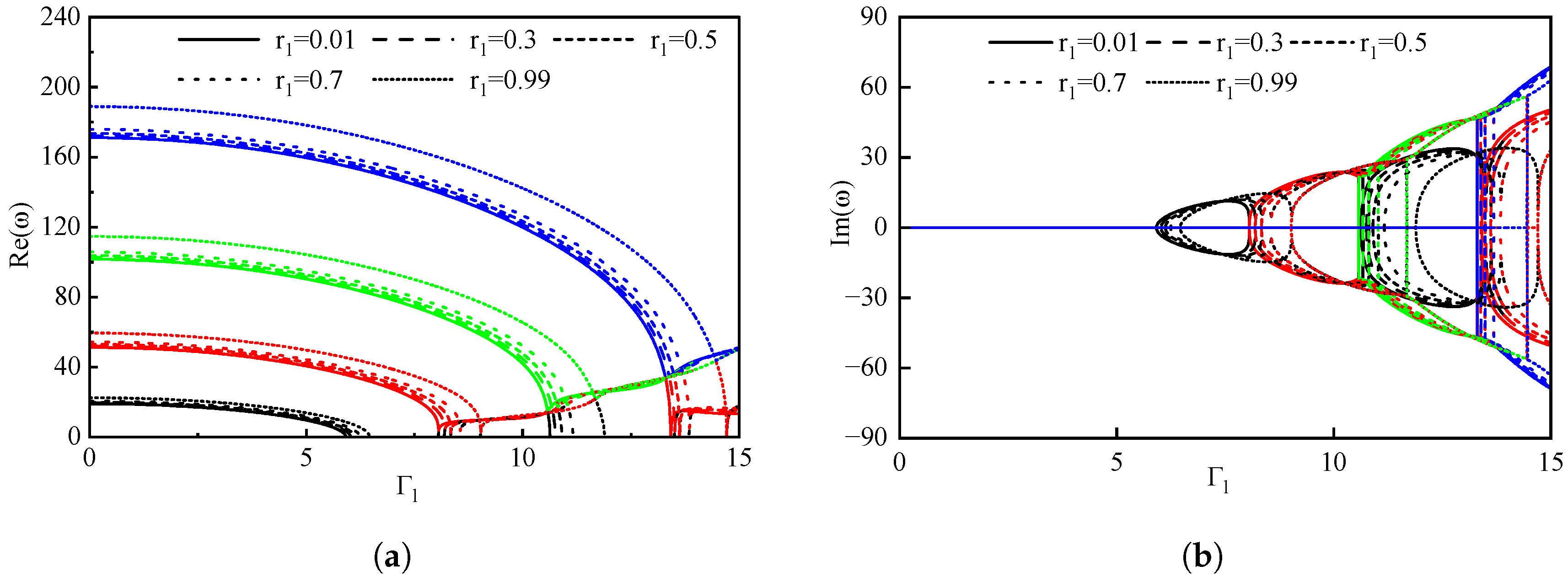
Table 2 delineates the convergence of the natural frequency of the pipe f r in various combinations of rotational stiffness factors and gas volume fractions, with the truncation order N W increasing from 6 to 12. When the rotational stiffness factors r 1 and r 2 are near 0, the maximum deviation between the natural frequency of the pipe and the under simply supported boundary conditions is minimal, at 0.03%. In contrast, when factors r 1 and r 2 approximate 1, this deviation relative to the frequency under clamped-clamped boundary conditions decreases further, to 0.004%. These findings underscore the efficacy of employing limiting rotational stiffness conditions to emulate classical boundary conditions in computational analysis, thus presenting a reliable approach for the dynamic modeling of pipes subject to various boundary conditions. In addition, stabilization of the frequencies for different orders is observed at N W = 12 , with a maximum error of 0. 0035% compared to N W = 10 . In terms of both precision and computational efficiency, N W = 10 is selected for subsequent computations, achieving a balance between precise frequency prediction and manageable computational demand. Figure 2 shows the natural frequency of the pipe with various gas fractions under different truncation order and boundary conditions.
Figure 3 illustrates the variation in deflection ( w ( 1 / 2 , τ ) ) at the tube’s midpoint over the time interval [ 290 , 300 ] , considering the dimensionless velocity of liquid Γ l = 4 and the volume fraction of gas ε g = 0.5 . The periodic nature of the pipe’s vibration, which varies with the rotational stiffness factor, is evident. As the rotational stiffness factor increases, the pipe’s boundary conditions transition from being simply supported at both ends to fully clamped. This transition initially results in a reduction in the vibration displacement at the midpoint, followed by an increase, whereas the vibration frequency steadily rises. Notably, at a rotational stiffness factor value of 1, the midpoint exhibits minimal vibration displacement, underscoring the significant influence of boundary conditions on the dynamic behavior of the pipe.
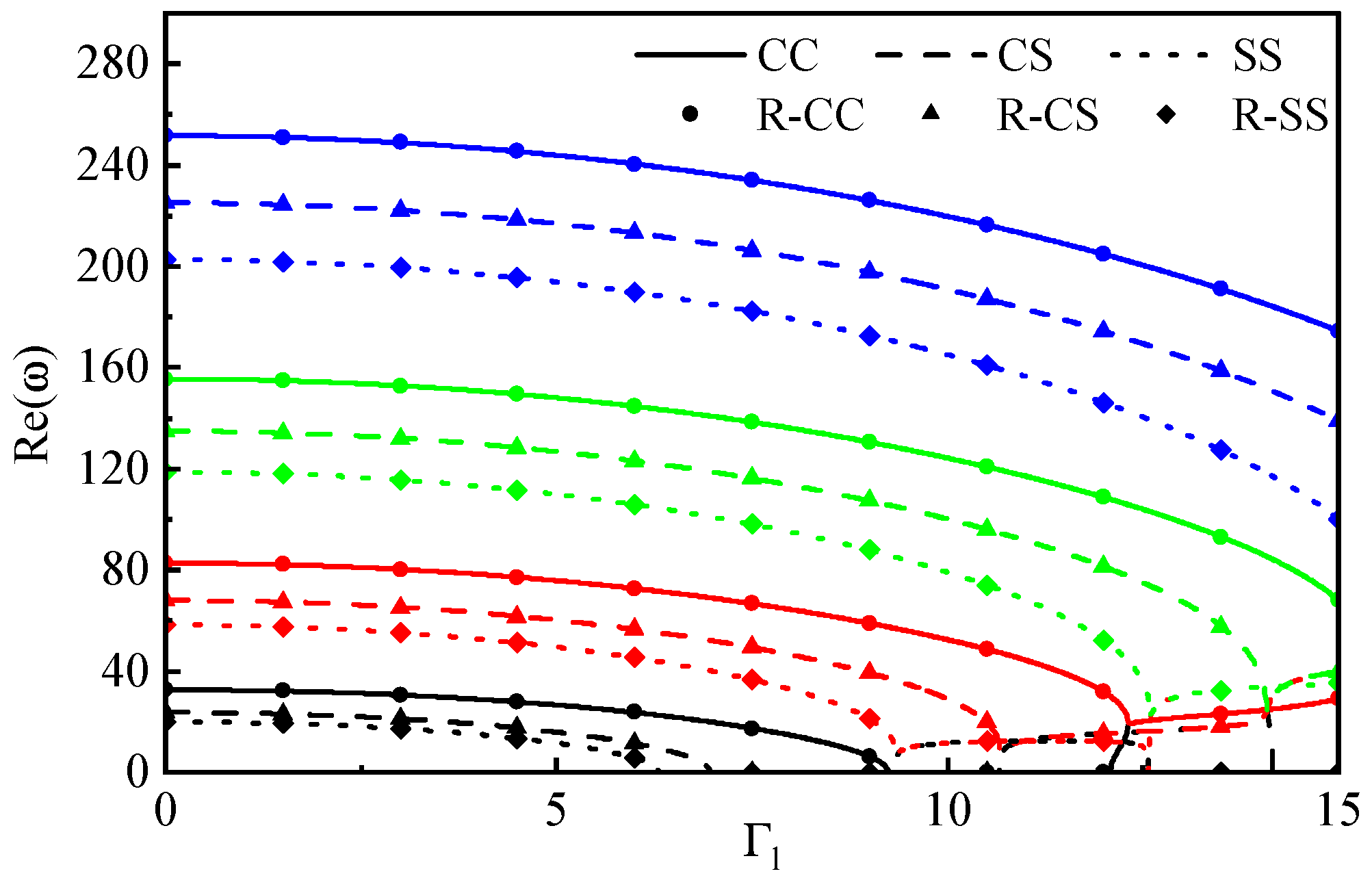
As illustrated in Figure 4, Fu et al. [22] conducted an investigation into the dynamic properties of a pipe made from functionally graded materials conveying gas-liquid flow under classical boundary conditions. Their study revealed that pipes demonstrate the greatest stability under CC boundary conditions and the lowest stability under SS boundary conditions. In the figure, the colors black, red, green, and blue represent the first- and fourth-order frequencies of pipe vibration, respectively. This color scheme for the representation of vibration frequency is consistent throughout all figures. Unless otherwise specified in the subsequent sections, this specification is adhered to for the first four complex frequencies. For comparative purposes, the rotational stiffness factors were determined as follows: r 1 = r 2 = 0.9999 to approximate fixed support boundary conditions (R-CC); r 1 = 3.3333 × 10 8 , r 2 = 3.3333 × 10 8 to approximate simply supported boundary conditions (R-SS); and r 1 = 0.9999 , r 2 = 3.3333 × 10 8 to emulate a configuration with one end fixed and the other simply supported (R-CS). Comparisons with the existing literature indicate that these three derived types of boundary conditions closely resemble the vibration frequencies observed in pipes under classical boundary conditions. This underscores the accuracy of using restricted rotational stiffness as a credible boundary condition model, evidencing its efficacy in replicating classical boundary behaviors in dynamic analysis of pipes.
Figure 3 and Figure 4 validate the vibration displacement and frequency of the pipeline under classical boundary conditions and rotationally restrained stiffness boundary conditions, respectively. When the rotational stiffness factors r 1 and r 2 are taken as extreme values, they correspond to the boundary conditions of simple support at both ends and fixed support at both ends under the classical boundary conditions, respectively. With increasing rotational fixing factor, the vibration displacement of the pipeline decreases, the vibration frequency increases, and the stability of the pipeline is enhanced. Moreover, the stability of the fixed support conditions at both ends is stronger than that of the simple support at both ends under the classical boundary conditions.

3. Results and Discussion

Employing the proposed GITT solution methodology for conveying two-phase flow under rotationally restricted boundary conditions, this investigation evaluates the effects of gas volume fraction and variations in rotational stiffness on the dynamic behavior of two-phase flow pipes. The research further delineates the natural frequencies associated with various vibration modes of the pipe, described through vibrational displacement. The primary focus of this study is on examining the dynamic characteristics of the pipe under subcritical flow velocities, utilizing rotational stiffness parameters r 1 = 3.3333 × 10 8 and r 2 = 3.3333 × 10 8 , alongside a dimensionless liquid velocity Γ l = 4 , to execute calculations for conditions approximating simply supported boundaries. The parameters utilized in these calculations are detailed in Table 3.

3.1. The Effects of the Gas Volume Fraction ε g

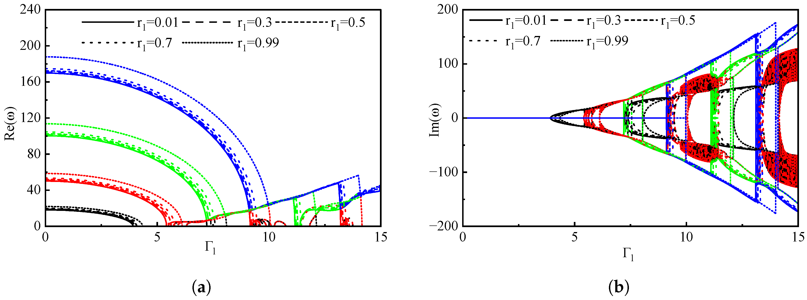
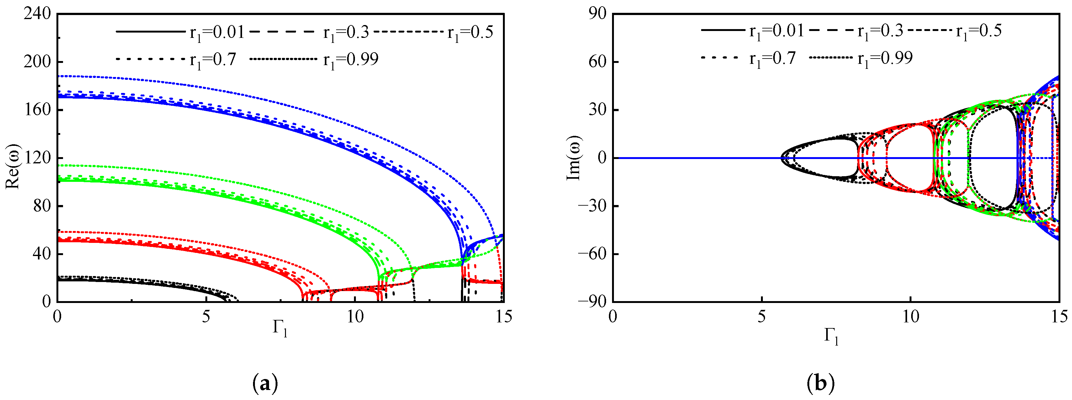
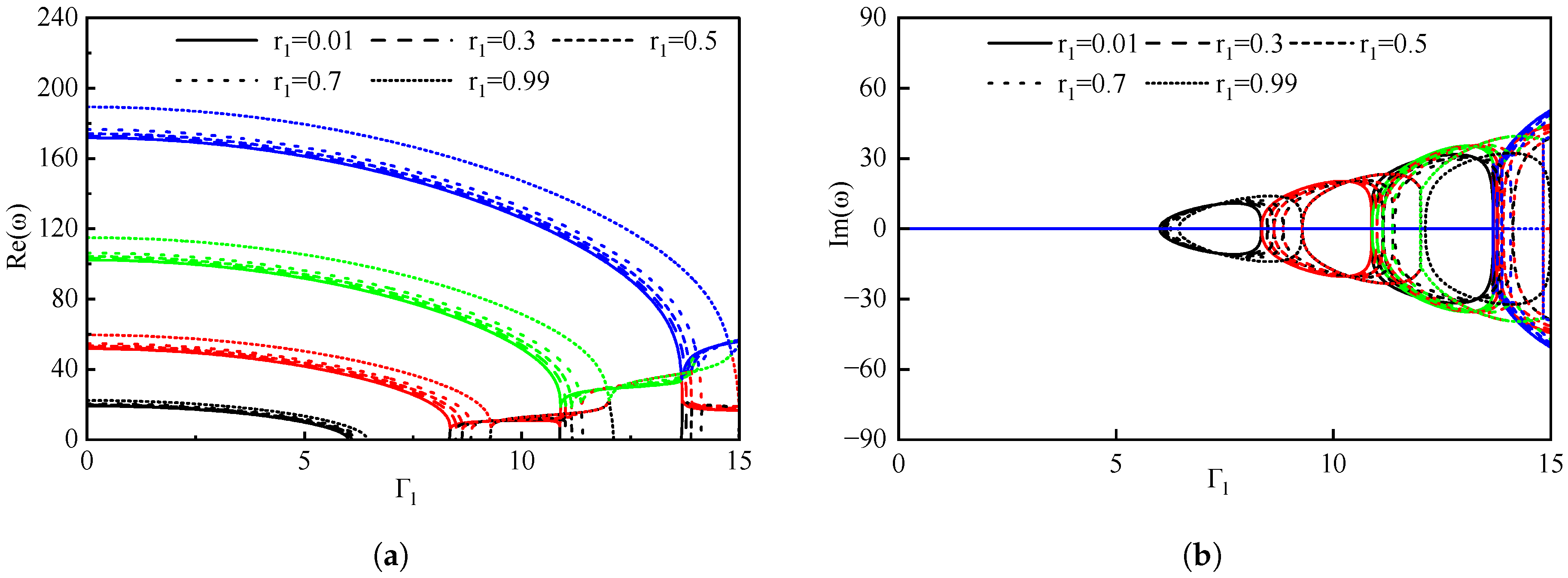
This section investigates the influence of gas volume fraction variations on pipeline vibration frequency under different boundary conditions. The boundary condition at the right end is assumed to be rotationally restricted according to r 2 = 0.5 , while the gas volume fraction ε g is systematically varied in increments of 0, 0.1, 0.5, 0.9, and 0.99. The rotational stiffness factor at the proximal end of the pipe is assumed to have values of r 1 = 0.01, 0.3, 0.5, 0.7, and 0.99, respectively. The dynamic characteristics of the pipe are examined under these disparate gas volume fractions, with Figure 5, Figure 6, Figure 7, Figure 8 and Figure 9 elucidating the effect of ε g on the initial four natural frequencies and the overall stability of the pipe.
The fluctuations in the first four natural frequencies of the pipe in relation to distinct rotational stiffness parameters r 1 at ε g = 0 , r 2 = 0.5 are illustrated in Figure 5. When ε g = 0 , the pipe transports a single-phase liquid. The findings indicate that as the dimensionless fluid flow velocity increases to 6.98, the first-order complex frequency diminishes to zero, resulting in the onset of buckling instability within the pipe. As the dimensionless fluid flow velocity attains 9.27, the first-order critical flow velocity becomes nonzero, thereby stabilizing the pipe. At a dimensionless fluid velocity of 9.38, the first-order complex frequency remains steady, and coupled flutter is detected in the first order. With an increase in dimensionless fluid velocity to 11.71, the first-order complex frequency approaches zero, effecting the termination of the first-order coupled flutter. At a dimensionless fluid velocity of 11.92, the second- and third-order complex frequencies converge, initiating a second and third-order coupled flutter. Upon reaching a dimensionless fluid flow velocity of 14.45, the second- and third-order coupled flutter ceases, whereas the first- and second-order coupled flutter reemerges. Ultimately, at a flow velocity of 14.62, a third- and fourth-order coupled flutter is manifested.
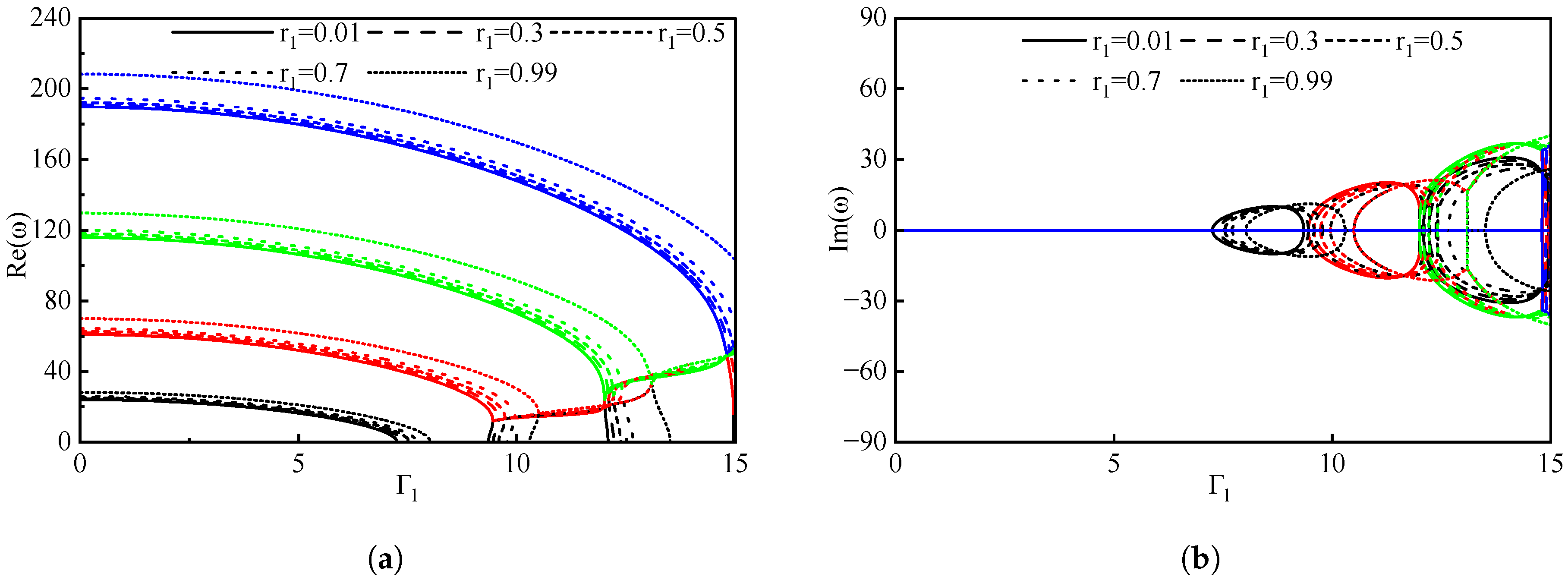
Under conditions ε g = 0.1 and r 2 = 0.5 , the variations in the first four natural frequencies of the pipe are illustrated in Figure 6. Within this analysis, the rotational stiffness parameters r 1 are considered to vary between 0.01 and 0.99. At the point ε g = 0.1 , the liquid phase occupies the majority of the volume of the tube. The findings indicate that as the dimensionless fluid flow velocity increases, there is a corresponding decrease in the first four natural frequencies. When the dimensionless flow velocity reaches a value of 6.75, the complex frequency of the first order approaches zero, signifying the onset of buckling instability within the pipe. As the flow velocity continues to increase to 9.01, the first-order critical flow velocity becomes nonzero, reinstating the stability of the pipe. Further increment in dimensionless velocity leads to constant 1st-order complex frequency at 9.09, alongside the occurrence of 1st-order coupled flutter. Upon the velocity reaching 11.50, both the first- and second-order complex frequencies converge towards zero, resulting in the cessation of the 1st and 2nd-order coupled flutter phenomenon. At a flow velocity of 11.58, there is a convergence of the 2nd and 3rd order complex frequencies, giving rise to 2nd and 3rd-order coupled flutter. As the dimensionless fluid flow velocity further increases to 14.24, the second- and third-order coupled flutter dissipates, while the 1st and 2nd-order coupled flutter reemerges. Finally, at a flow velocity of 14.27, the emergence of 3rd- and 4th-order coupled flutter is observed.
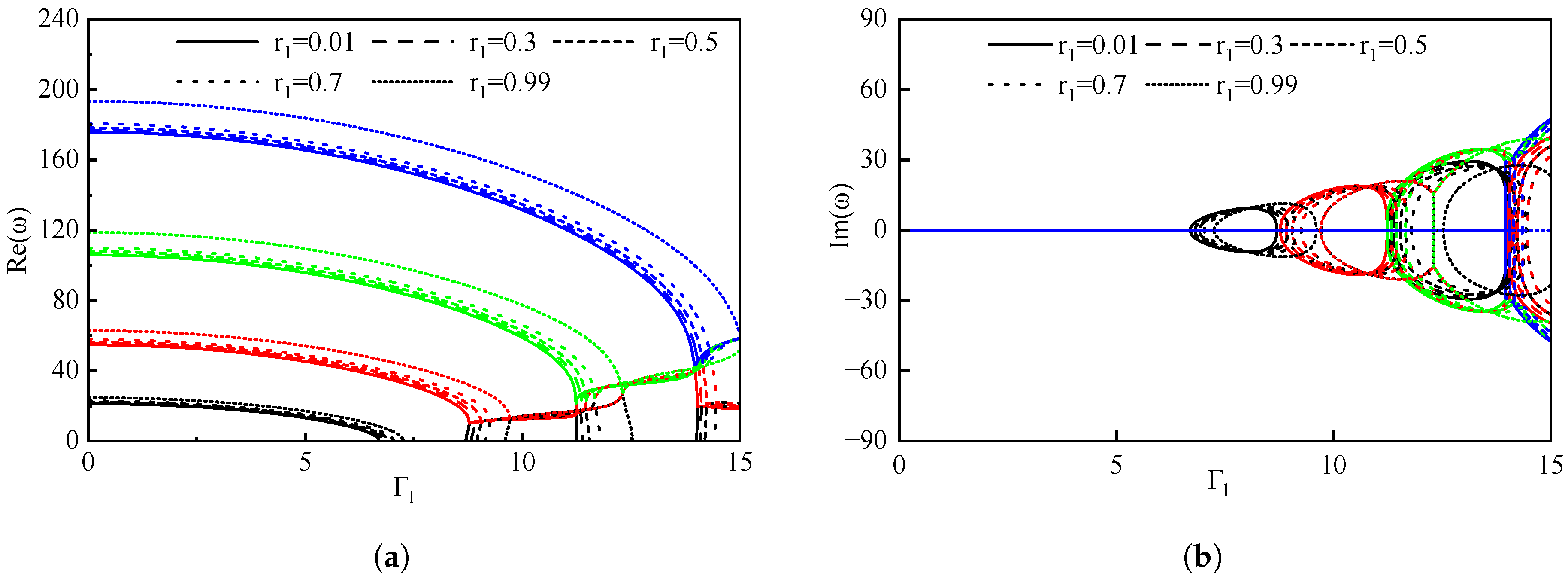
The variations in the first four natural frequencies of the pipe as functions of various rotational stiffness parameters r 1 at ε g = 0.5 , r 2 = 0.5 are illustrated in Figure 7. When ε g = 0.5 , the volumes of liquid and gas phases within the tube are equal. The findings indicate that as the dimensionless fluid flow velocity increases to 6.49, the first order complex frequency diminishes to zero, resulting in buckling instability of the pipe. As the dimensionless fluid flow velocity attains 8.75, the first-order critical flow velocity becomes nonzero, thus stabilizing the pipe. At a dimensionless fluid velocity of 8.78, the first-order complex frequency remains steady, and coupled flutter is detected in the first order. As the dimensionless fluid velocity further escalates to 11.25, the first-order complex frequency converges toward zero, leading to the cessation of first-order coupled flutter. Concurrently, the second- and third-order complex frequencies converge, initiating second- and third-order coupled flutter. Upon reaching a dimensionless fluid flow velocity of 13.97, the second- and third-order coupled flutter cease, whereas the first- and second-order coupled flutter reappear when the flow velocity attains 14.02. At a flow velocity of 14.62, the third- and fourth-order coupled flutter is observed.
Figure 8 illustrates the variation in the first four natural frequencies of the tube as the dimensionless liquid flow rate increases, as examined in previous studies ε g = 0.9 , r 2 = 0.5 . At a dimensionless flow velocity of 6.12, the complex frequency of the first mode asymptotically approaches zero, signaling the onset of buckling instability within the pipe. As the flow velocity progresses to 8.34, the first-order critical flow velocity becomes positive, thereby reinstating the pipe’s stability. Upon further increments in dimensionless velocity, at a velocity of 9.09, the first-order complex frequency stabilizes, and a first-order coupled flutter is detected. When the velocity reaches 10.81, both the first- and second-order complex frequencies tend towards zero, bringing an end to the first- and second-order coupled flutter phenomenon. Subsequently, the second- and third-order complex frequencies converge, resulting in simultaneous second- and third-order coupled flutter. At a flow velocity of 13.63, first- and second-order coupled flutter reoccurs. Ultimately, as the dimensionless fluid flow velocity advances to 13.49, the second- and third-order coupled flutter disappears, while the third- and fourth-order coupled flutter becomes evident.
Figure 9 illustrates the variation in the first four natural frequencies of the tube corresponding to incremental dimensionless liquid flow rates at ε g = 0.99 and r 2 = 0.5 . At ε g = 0.99 , the dimensionless flow velocity of 4.09 signifies the point at which the first-order complex frequency approaches zero, indicating the onset of buckling instability within the pipe. As the flow velocity increases to 5.73, the first-order critical flow velocity becomes non-zero, thereby reinstating the stability of the pipe. Concurrently, the first-order complex frequency remains unchanged and the first-order coupled flutter is evident. Upon reaching a velocity of 7.39, the first- and second-order complex frequencies simultaneously approach zero, resulting in the cessation of the 1st- and 2nd-order coupled flutter phenomenon. The convergence of the second- and third-order complex frequencies occurs, accompanied by the occurrence of second- and third-order coupled flutter. As the dimensionless fluid flow velocity is further increased to 9.26, the coupled flutter of the second and third orders dissipates, while coupled flutters of the third and fourth orders manifest. Ultimately, at a flow velocity of 9.39, the first- and second-order coupled flutters reemerge and persist until the flow velocity rises to 11.41.
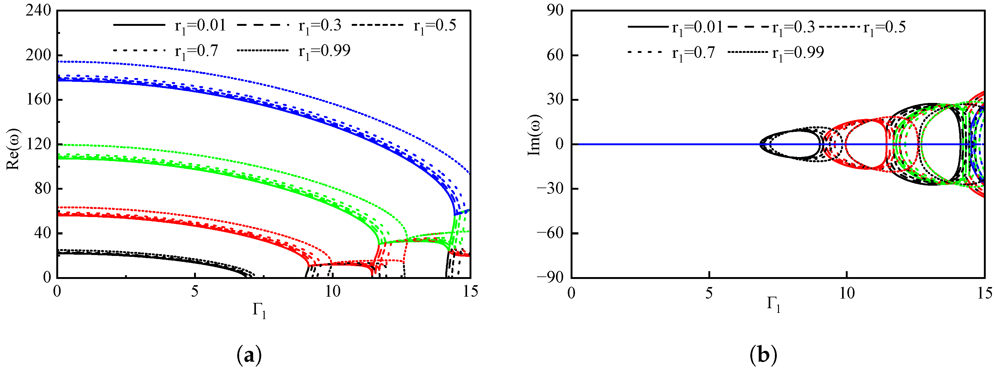
As demonstrated in Figure 5, Figure 6, Figure 7, Figure 8 and Figure 9, when the pipe is completely saturated with the liquid phase, the dimensionless first-order critical fluid flow velocity surpasses the critical flow velocity observed under two-phase flow conditions. Figure 10 shows the real part of the first four natural frequencies varying with the gas volume fraction. With an increase in gas volume fraction, the complex frequency of each vibration mode of the tube is reduced, thereby diminishing the first-order critical flow velocity and leading to a corresponding decline in the tube stability. Furthermore, the reduction in the velocity of coupling flutter across all orders results in more frequent occurrences of coupling flutter, rendering the dynamic behavior of the pipe more complex.

3.2. The Impact of Boundary Conditions on Pipes

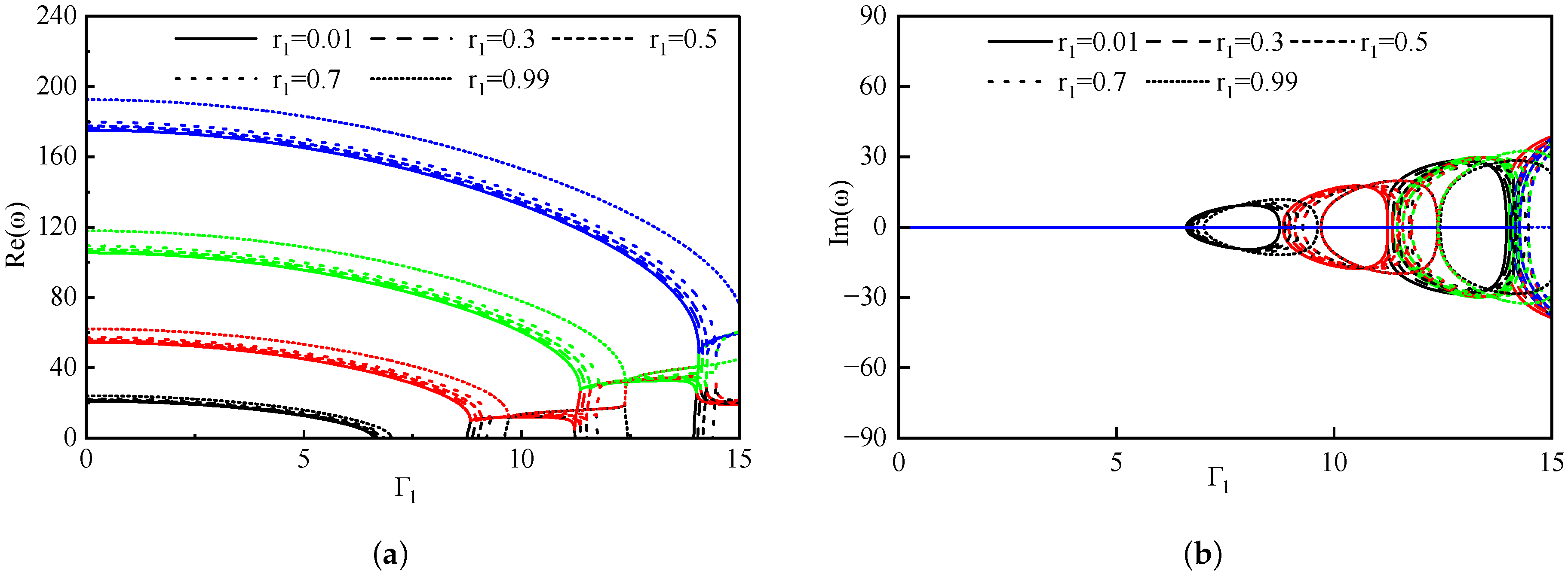
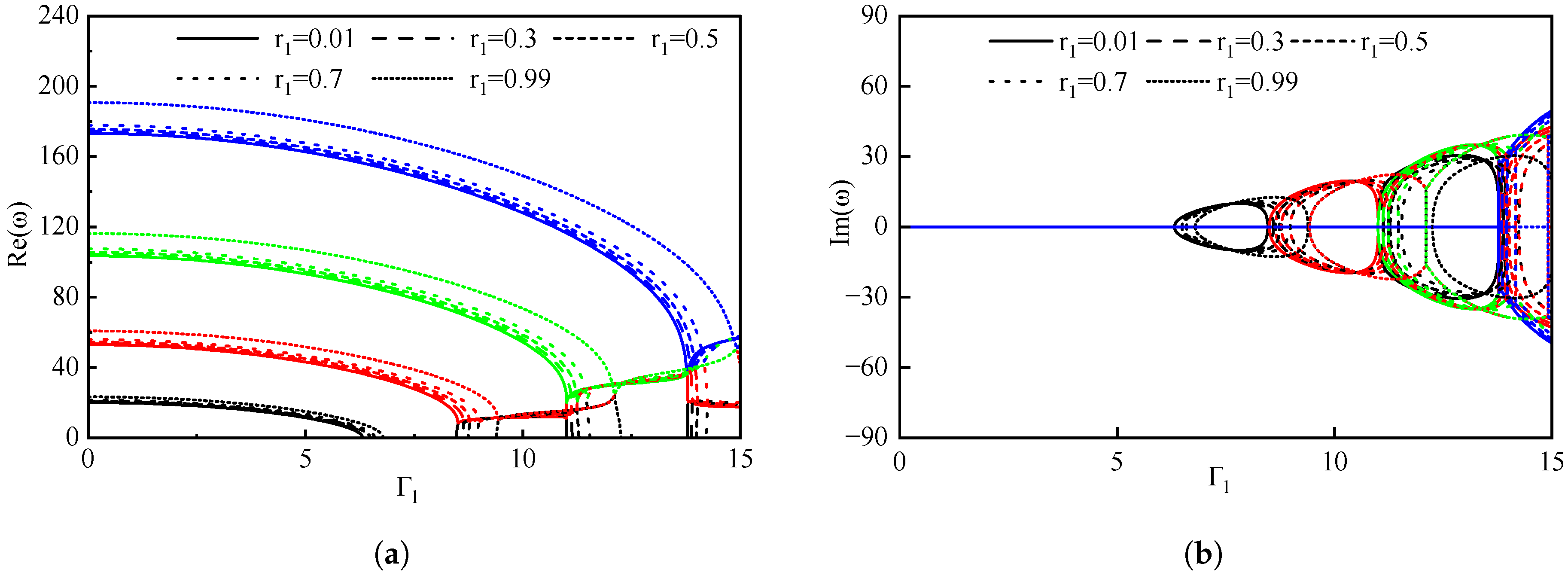
This section examines the impact of boundary conditions on the natural frequencies of the pipe up to the fourth order. The volume fraction of the gas is maintained at a constant value as denoted by ε g = 0.5 , while the rotational stiffness factor r 1 is varied to 0.01, 0.3, 0.5, 0.7, and 0.99, respectively. Furthermore, the rotational stiffness factor r 2 spans a range from 0.01 to 0.99. Table 4 presents the dimensionless fluid velocity of the pipe across various vibration states and boundary conditions.
Utilizing ε g = 0.5 and r 2 = 0.01 as examples in Figure 11, in the scenario where r 1 = 0.01 , the pipe transitions to a critical instability state of the first order when the flow velocity attains 5.67, which constitutes the critical velocity of the first order, denoted as V c r 1 . As the dimensionless fluid flow velocity reaches 8.25, the critical flow velocity of the first order becomes non-zero, thereby stabilizing the pipe, which defines the first critical stabilization velocity, referred to as V c r 1 s . At a dimensionless fluid velocity of 8.25, the complex frequency of the first order remains constant, and coupled flutter of the first order is detected, with the fluid velocity termed as velocity V 12 . Upon an increase in dimensionless fluid velocity to 10.78, the complex frequency of the first order approaches zero, leading to the termination of the first-order coupled flutter, while the second- and third-order coupling flutter manifests simultaneously; this velocity is indicated as V 12 d . Until the dimensionless velocity attains 10.80, the second- and third-order coupling flutter ceases, with this flow velocity denoted by V 23 . When the dimensionless fluid flow velocity escalates to 14.45, the second- and third-order coupled flutter vanishes, with the flow velocity referred to as V 12 a . As the dimensionless fluid velocity further increases to 14.62, the third- and fourth-order coupled flutter emerges, with this flow velocity denoted as V 34 .
Table 5 delineates the internal fluid velocities within the pipe across several vibrational states under varying boundary conditions. In particular, the dimensionless fluid velocity manifests an increase in conjunction with an elevation in the rotational stiffness factor r 2 when r 1 = 0.01 is considered. Conversely, when r 2 = 0.01 , an augmentation in the dimensionless fluid velocity is discernible as the rotational stiffness factor r 1 rises. Comparable patterns are discerned under the other boundary conditions.
Figure 7 and Figure 11, Figure 12, Figure 13 and Figure 14 illustrate the vibration frequency of pipelines under various boundary conditions when the gas volume coefficient ε g = 0.5 . To study the effect of r 2 change on the dynamic behavior of the pipeline, r 1 = 0.5 was fixed and r 2 changed from 0.01 to 0.99. The vibration frequencies of r 1 = 0.5 and r 2 = 0.01 , 0.3 , 0.5 , 0.7 , 0.99 can be observed in Figure 7 and Figure 11, Figure 12, Figure 13 and Figure 14, respectively. when the rotational stiffness factor r 2 is varied from 0.01 to 0.99, the dimensionless critical fluid velocity associated with the first-order mode increases from 5.81 to 6.16, 6.49, 6.81, and 7.54, respectively. Currently, the dimensionless critical velocity of the first-order coupled flutter increases from 8.54 to 8.64, 8.78, 9.05 and 9.74, respectively. Furthermore, the dimensionless critical fluid velocity pertinent to the second- and third-order coupled flutter escalates from 11.05 to 13.88, 13.97, 14.16, and 14.99, respectively. Analogously, the critical fluid velocity regarding the third- and fourth-order coupled flutter rises from 13.80 to 13.88, 13.97, 14.16, and 14.99, respectively. These findings suggest that an increase in the rotational stiffness factor results in a significant increase in the vibration frequency of the pipe.

4. Conclusions

This research examines the dynamic behavior of a rotationally restricted pipe transmitting two-phase flow through the application of the GITT technique. The rotationally constrained boundary conditions present a more realistic alternative for engineering applications compared to the traditional simply supported and clamped boundary conditions. In comparison to the classical boundary conditions, the rotationally constrained boundary conditions maintain the precision of the traditional methods. By modulating the rotational stiffness parameters, the boundary conditions can seamlessly transition from a simply supported state to a fully clamped state, thereby facilitating a more adaptable and realistic simulation of diverse boundary scenarios. For instance, when λ 1 = 1 × 10 7 , the boundary condition closely resembles a simply supported configuration, while λ 1 = 1 × 10 5 represents a clamped boundary condition.
The findings indicate that the GITT exhibits high precision and accuracy in numerical computations, demonstrating excellent concordance with classical models, thus confirming its efficacy in capturing the intricate dynamics of such systems. Using this model, an exploration of the effects of flow parameters on pipe vibration was carried out under varying boundary conditions through parametric analysis. Resonance phenomena of different orders were investigated, and the influence of rotational constraint stiffness on the dynamic stability of the two-phase flow transport pipe was subject to comprehensive analysis.
In examining the impact of gas volume fraction variation on the dynamic stability of two-phase flow transmission pipes, it is evident that an increase in gas volume fraction results in a gradual decline in both the first-order critical flow velocity and the pipe’s vibration frequency. Furthermore, the coupling flutter velocity for each mode also diminishes, leading to more intricate dynamic behavior and a reduction in pipe stability. These observations underscore the substantial influence of gas volume fraction on the dynamic stability and vibration characteristics of the pipe system. Simultaneously, an increase in rotational stiffness parameters corresponds to a progressive rise in the first-order vibration frequency and critical velocity, as well as the coupling flutter velocity of each mode, thereby augmenting the pipe’s dynamic stability. Moreover, alterations in the rotational factor r 2 exert a more pronounced effect on the dynamic stability of the pipe compared to variations in r 1 .

Author Contributions

G.F.: Formal analysis, Methodology, Writing—review and editing, Funding acquisition, Supervision. H.J.: Data curation. A.Z.: Data curation. X.W.: Software, Writing—original draft. B.W.: Data curation. B.S.: Funding acquisition. J.S.: Funding acquisition, Conceptualization, Writing—review and editing. All authors have read and agreed to the published version of the manuscript.

Funding

The work was funded by the Key Research and Development Program of Shandong Province (Major Innovation Project) [2022CXGC020405, 2023CXGC010415], the National Natural Science Foundation of China [52171288], and the financial support from CNPq, FAPERJ, ANP, Embrapii, and China National Petroleum Corporation (CNPC) Brazil.

Data Availability Statement

The data presented in this study are available on request from the corresponding author.

Conflicts of Interest

The authors declare that they have no known competing financial interests or personal relationships that could have appeared to influence the work reported in this paper.

References

  1. Païdoussis, M.; Li, G. Pipes Conveying Fluid: A Model Dynamical Problem. J. Fluids Struct. 1993, 7, 137–204. [Google Scholar] [CrossRef]
  2. Li, T.; An, C.; Duan, M.; Huang, H.; Liang, W. Effect of the boundary conditions on the dynamic behaviours of subsea free-spanning pipelines. Int. J. Marit. Eng. 2018, 160 A2. [Google Scholar] [CrossRef]
  3. Wang, B.; Fu, G.; Wang, X.; Su, J.; Jiao, H.; Sun, B. Vibration analysis of a pipe conveying two-phase flow with improved drift-flow model. Appl. Ocean. Res. 2025, 161, 104647. [Google Scholar]
  4. Zhou, K.; Dai, H.; Wang, L.; Ni, Q.; Hagedorn, P. Modeling and nonlinear dynamics of cantilevered pipe with tapered free end concurrently subjected to axial internal and external flows. Mech. Syst. Signal Process. 2022, 169, 108794. [Google Scholar] [CrossRef]
  5. Ortega, A.; Rivera, A.; Larsen, C. Flexible riser response induced by combined slug flow and wave loads. In International Conference on Offshore Mechanics and Arctic Engineering; American Society of Mechanical Engineers: New York, NY, USA, 2013; Volume 55379, p. V04BT04A008. [Google Scholar]
  6. Gu, J.; Duan, M. Integral transform solution for fluid force investigation of a flexible circular cylinder subject to vortex-induced vibrations. J. Mar. Sci. Technol. 2016, 21, 663–678. [Google Scholar] [CrossRef]
  7. Zhang, T.; Zhang, S.; Yang, D.; Huang, G. Numerical investigation on competitive mechanism between internal and external effects of submarine pipeline undergoing vortex-induced vibration. Ocean. Eng. 2022, 266, 112744. [Google Scholar] [CrossRef]
  8. Païdoussis, M. Pipes conveying fluid: A fertile dynamics problem. J. Fluids Struct. 2022, 114, 103664. [Google Scholar] [CrossRef]
  9. Païdoussis, M. Dynamics of cylindrical structures in axial flow: A review. J. Fluids Struct. 2021, 107, 103374. [Google Scholar] [CrossRef]
  10. An, C.; Duan, M.; Estefen, S.F.; Su, J. Structural and Thermal Analyses of Deepwater Pipes; Springer: Berlin/Heidelberg, Germany, 2021. [Google Scholar]
  11. An, C.; Su, J. Dynamic behavior of pipes conveying gas–liquid two-phase flow. Nucl. Eng. Des. 2021, 292, 204–212. [Google Scholar] [CrossRef]
  12. Yih, T.S.; Griffith, P. Unstayed Momentum Fluxes in Two-Phase Low and the Vibration of Nnclear Reactor Components; Massachusetts Institute of Technology, Engineering Projects Lab.: Cambridge, UK, 1968. [Google Scholar]
  13. Monette, C.; Pettigrew, M.J. Fluidelastic instability of flexible tubes subjected to two-phase internal flow. J. Fluids Struct. 2004, 19, 943–956. [Google Scholar] [CrossRef]
  14. Cargnelutti, M.F.; Belfroid, S.P.C.; Schiferli, W. Two-Phase flow-induced forces on bends in small scale tubes. J. Press. Vessel. Technol. 2010, 102, 041305. [Google Scholar] [CrossRef]
  15. Miwa, S.; Mori, M.; Hibiki, T. Two-phase flow induced vibration in piping systems. Prog. Nucl. Energy 2015, 78, 270–284. [Google Scholar] [CrossRef]
  16. Adegoke, A.S.; Oyediran, A.A. Natural frequencies, modes and critical velocities of top tensioned cantilever pipes conveying pressurized steady two-phase flow under thermal loading. Res. Eng. Struct. Mater. 2018, 4, 270–284. [Google Scholar] [CrossRef]
  17. Ebrahimi-Mamaghani, A.; Sotudeh-Gharebagh, R.; Zarghami, R.; Mostoufi, N. Dynamics of two-phase flow in vertical pipes. J. Fluids Struct. 2019, 87, 150–173. [Google Scholar] [CrossRef]
  18. Li, F.; An, C.; Duan, M.; Su, J. Combined damping model for dynamics and stability of a pipe conveying two-phase flow. Ocean. Eng. 2020, 195, 106683. [Google Scholar] [CrossRef]
  19. Fu, G.; Tuo, Y.; Su, J.; Wang, K.; Li, L.; Sun, B. Nonlinear dynamics of viscoelastic pipe conveying pulsating fluid subjected to base excitation. China Ocean. Eng. 2023, 37, 781–793. [Google Scholar] [CrossRef]
  20. Ortiz-Vidal, L.E.; Castillo, D.G.; Valverde, Q. Theoretical study on the dynamic behavior of pipes conveying gas-liquid flow. In Proceedings of the MATEC Web of Conferences, EDP Sciences, Sofia, Bulgaria, 21 September 2017; Volume 148, p. 01004. [Google Scholar]
  21. Lou, W.; Wang, Z.; Li, P.; Sun, X.; Sun, B.; Liu, Y.; Sun, D. Wellbore drift flow relation suitable for full flow pattern domain and full dip range. Pet. Explor. Dev. 2022, 49, 694–706. [Google Scholar] [CrossRef]
  22. Fu, G.; Wang, X.; Wang, B.; Su, J.; Wang, K.; Sun, B. Dynamic behavior of axially functionally graded pipe conveying gas–liquid two-phase flow. Appl. Ocean. Res. 2024, 142, 103827. [Google Scholar] [CrossRef]
  23. Ponte, P.J.V.; Ritto, T.G.; Deü, J.F. Dynamic analysis of a pipe conveying a two-phase fluid considering uncertainties in the flow parameters. J. Braz. Soc. Mech. Sci. Eng. 2020, 42, 626. [Google Scholar] [CrossRef]
  24. Guo, Y.; Zhu, B.; Zhao, X.; Chen, B.; Li, Y. Dynamic characteristics and stability of pipe-in-pipe system conveying two-phase flow in thermal environment. Appl. Ocean. Res. 2020, 103, 102333. [Google Scholar] [CrossRef]
  25. Zhang, J.; Zhao, Q.; Wang, X.; Ullah, S.; Zhao, D.; Civalek, Ö.; Xue, C.; Qi, W. New exact analytical thermal buckling solutions of composite thin plates with all edges rotationally-restrained. Mech. Adv. Mater. Struct. 2020, 31, 3518–3530. [Google Scholar] [CrossRef]
  26. Chen, Q.; Qiao, P. Post-buckling behavior of imperfect laminated composite plates with rotationally-restrained edges. Compos. Struct. 2015, 125, 117–126. [Google Scholar] [CrossRef]
  27. Tang, X.; Guo, C.; Li, F.; Zhang, R.; Song, D.; Fu, P.; Liu, H. Thermal buckling analysis of rotationally-restrained orthotropic thin plates utilizing a two-dimensional improved Fourier series approach. Meccanica 2023, 58, 1443–1464. [Google Scholar] [CrossRef]
  28. Qiao, P.; Shan, L. Explicit local buckling analysis of rotationally restrained composite plates under biaxial loading. Int. J. Struct. Stab. Dyn. 2007, 7, 487–517. [Google Scholar] [CrossRef]
  29. Hu, W.; Han, S.; Deng, Z. Analyzing dynamic response of non-homogeneous string fixed at both ends. Int. J.-Non-Linear Mech. 2012, 47, 1111–1115. [Google Scholar] [CrossRef]
  30. Lee, J. Free vibration analysis of beams with non-ideal clamped boundary conditions. J. Mech. Sci. Technol. 2013, 27, 297–303. [Google Scholar] [CrossRef]
  31. Shahin, R.I.; Ahmed, M.; Yehia, S.A. Elastic Buckling of Prismatic Web Plate under Shear with Simply-Supported Boundary Conditions. Buildings 2023, 13, 2879. [Google Scholar] [CrossRef]
  32. Cheng, X.; Nie, J.; Zhao, L.; Shi, W. The thermal bend of RTP with one edge clamped and two edges simply supported and one edge free. Arch. Appl. Mech. 2015, 85, 287–302. [Google Scholar] [CrossRef]
  33. Jeong, J.; Lim, C.; Joeng, D.; Kook, S. A Study on the Dynamic Behavior of a Various Buried Pipeline. J. Earthq. Eng. Soc. Korea 2006, 10, 15–24. [Google Scholar] [CrossRef]
  34. Choi, H.S. Free spanning analysis of offshore pipelines. Ocean. Eng. 2001, 28, 1325–1338. [Google Scholar] [CrossRef]
  35. He, Y.; Duan, M.; Su, J. Bending of rectangular orthotropic plates with rotationally restrained and free edges: Generalized integral transform solutions. Eng. Struct. 2021, 247, 113129. [Google Scholar] [CrossRef]
  36. Zhou, J.; Chang, X.; Xiong, Z.; Li, Y. Stability and nonlinear vibration analysis of fluid-conveying composite pipes with elastic boundary conditions. Thin-Walled Struct. 2022, 179, 109597. [Google Scholar] [CrossRef]
  37. Xu, Y.; Zhang, L.; Wei, H.; Zhang, Z.; Yang, F.; Hu, H.; Hu, Y. Nonlinear dynamics of viscoelastic fluid-conveying pipe installed within uniform external cross flow by pipe clamps. Appl. Ocean. Res. 2023, 135, 103547. [Google Scholar] [CrossRef]
  38. Azliana, N.; Akmar, A.; Sallih, N.; Harith Irfan Ishak, M. Natural Frequency Analysis of Pipe with Different Boundary Conditions Using Analytical and Finite Element Method; Springer: Berlin/Heidelberg, Germany, 2022; pp. 559–570. [Google Scholar]
  39. Cotta, R.M. Benchmark results in computational heat and fluid flow: The integral transform method. Int. J. Heat Mass Transf. 1994, 37, 381–393. [Google Scholar] [CrossRef]
  40. Cotta, R.M.; Lisboa, K.M.; Curi, M.F.; Balabani, S.; Quaresma, J.N.N.; Perez-Guerrero, J.S.; Macêdo, E.N.; Amorim, N.S. A review of hybrid integral transform solutions in fluid flow problems with heat or mass transfer and under Navier–Stokes equations formulation. Numer. Heat Transf. Part Fundam. 2019, 76, 60–87. [Google Scholar] [CrossRef]
  41. Cotta, R.M.; Naveira-Cotta, C.P.; Knupp, D.C. Nonlinear eigenvalue problem in the integral transforms solution of convection-diffusion with nonlinear boundary conditions. Int. J. Numer. Methods Heat Fluid Flow 2016, 26, 767–789. [Google Scholar] [CrossRef]
  42. Zhang, S.; Xu, L. Bending of rectangular orthotropic thin plates with rotationally restrained edges: A finite integral transform solution. Appl. Math. Model. 2017, 46, 48–62. [Google Scholar] [CrossRef]
Figure 1. Vertical pipe conveying two-phase flow with rotationaly restrained ends.
Jmse 13 01524 g001
Figure 2. The 3D plots of the natural frequency of pipe with various gas fraction under different truncation order and boundary conditions. (a) first-order. (b) second order. (c) third order and (d) fourth order.
Jmse 13 01524 g002
Figure 3. Comparison of midpoint vibration displacement in the pipe under different rotational stiffness parameters ( ε g = 0.5 , Γ l = 4 ). (a) The SS boundary conditions at both ends. (b) the CC boundary conditions at both ends. (c) Different rotational stiffness parameters boundary conditions at both ends ( r 2 = 0.9709 ).
Jmse 13 01524 g003
Figure 4. Verification of pipe vibration frequency under classical boundary conditions ( ε g = 0.5 , α E = 2 , α ρ = 1 , k = 1 ).
Jmse 13 01524 g004
Figure 5. The first four natural frequencies for ε g = 0 and r 2 = 0.5 . (a) real part. (b) imaginary part.
Jmse 13 01524 g005
Figure 6. The first four natural frequencies for ε g = 0.1 and r 2 = 0.5 . (a) real part. (b) imaginary part.
Jmse 13 01524 g006
Figure 7. The first four natural frequencies for ε g = 0.5 and r 2 = 0.5 . (a) real part. (b) imaginary part.
Jmse 13 01524 g007
Figure 8. The first four natural frequencies for ε g = 0.9 and r 2 = 0.5 . (a) real part. (b) imaginary part.
Jmse 13 01524 g008
Figure 9. The first four natural frequencies for ε g = 0.99 and r 2 = 0.5 . (a) real part. (b) imaginary part.
Jmse 13 01524 g009
Figure 10. The real part of the first four natural frequencies varying with the gas volume fraction (a) r 1 = r 2 = 0.3 . (b) r 1 = r 2 = 0.5 .
Jmse 13 01524 g010
Figure 11. The first four natural frequencies of the pipe have been evaluated under various boundary conditions ( ε g = 0.5 , r 2 = 0.01 ). (a) real part. (b) imaginary part.
Jmse 13 01524 g011
Figure 12. The first four natural frequencies of the pipe have been evaluated under various boundary conditions ( ε g = 0.5 , r 2 = 0.3 ). (a) real part. (b) imaginary part.
Jmse 13 01524 g012
Figure 13. The first four natural frequencies of the pipe have been evaluated under various boundary conditions ( ε g = 0.5 , r 2 = 0.7 ). (a) real part. (b) imaginary part.
Jmse 13 01524 g013
Figure 14. The first four natural frequencies of the pipe have been evaluated under various boundary conditions ( ε g = 0.5 , r 2 = 0.99 ), (a) real part. (b) imaginary part.
Jmse 13 01524 g014
Table 1. First-order critical flow velocity Γ l , c r of the pipe under different rotational stiffness factors and gas volume fractions.
Boundary Conditions ε g = 0.01 ε g = 0.5 ε g = 0.9
SS6.0725.6545.282
r 1 = 3.3333 × 10 8 , r 2 = 3.3333 × 10 8 6.0735.6555.286
(R-SS, λ 1 = × 10 7 , λ 2 = × 10 7 )
r 1 = 3.3333 × 10 8 , r 2 = 0.9709 7.7667.2206.751
(SR, λ 1 = × 10 7 , λ 2 = × 10 2 )
r 1 = 0.9709 , r 2 = 0.9709 8.3637.9547.573
(RR, λ 1 = × 10 2 , λ 2 = × 10 2 )
r 1 = 0.9999 , r 2 = 0.9709 8.3917.9877.609
(CR, λ 1 = × 10 5 , λ 2 = × 10 2 )
r 1 = 0.9999 , r 2 = 0.9999 8.4628.0557.675
(R-CC, λ 1 = × 10 5 , λ 2 = × 10 5 )
CC8.4638.0557.675
Table 2. The natural frequencies of the pipe under various rotational stiffness factor.
f r BC ε g = 0.01 ε g = 0.5 ε g = 0.9
NW= 6 8 10 12 6 8 10 12 6 8 10 12
1stSS14.29314.29314.29314.29312.47812.47712.47712.47711.00411.00411.00411.004
R-SS14.29314.29314.29314.29312.47812.47712.47712.47711.00411.00411.00411.004
SR20.94220.94120.94120.94119.17119.17119.17119.17117.88217.88217.88217.882
RR24.60924.60824.60824.60823.28323.28223.28223.28222.38022.38022.38022.380
CR24.95024.94924.94924.94923.63323.63223.63223.63222.73622.73622.73622.736
R-CC25.45925.45825.45825.45824.12524.12424.12424.12423.21923.21923.21923.219
CC25.46025.45925.45925.45924.12624.12624.12524.12523.22023.22023.22023.220
2ndSS47.20047.20047.19547.19444.30844.30544.30444.30442.11242.11042.11042.110
R-SS47.20047.20047.19547.19444.30844.30544.30444.30442.11242.11042.11042.110
SR57.54357.54057.54057.54054.66654.66454.66454.66452.54852.54752.54752.547
RR65.65765.65165.64965.64963.28163.27763.27663.27661.53761.53561.53461.534
CR66.65366.64766.64566.64464.29164.28864.28764.28662.55862.55662.55562.555
R-CC67.89667.89067.88867.88865.51065.50765.50665.50563.76363.76163.76063.760
CC67.89967.89267.89167.89065.51365.50965.50865.50863.76663.76363.76363.763
3rdSS97.89697.87797.87497.87294.42894.41894.41494.41491.88191.87691.87591.874
R-SS97.89697.87797.87497.87294.42894.41794.41494.41491.88191.87691.87591.874
SR111.922111.906111.903111.902108.496108.485108.483108.482106.022106.015106.014106.013
RR124.293124.280124.278124.277121.341121.333121.332121.331119.207119.202119.201119.201
CR126.254126.241126.239126.238123.326123.318123.317123.316121.208121.204121.203121.202
R-CC128.519128.507128.504128.503125.567125.559125.557125.557123.435123.431123.430123.429
CC128.524128.512128.509128.508125.572125.564125.562125.562123.440123.435123.434123.434
4thSS167.706167.594167.577167.572163.937163.855163.842163.839161.204161.150161.142161.140
R-SS167.706167.594167.578167.572163.938163.855163.842163.839161.204161.150161.142161.140
SR185.273185.171185.157185.153181.557181.481181.471181.468178.890178.841178.834178.833
RR201.603201.489201.473201.469198.291198.210198.199198.196195.908195.856195.849195.848
CR204.818204.702204.686204.682201.535201.453201.442201.440199.172199.120199.113199.111
R-CC208.381208.265208.249208.245205.074204.992204.981204.979202.697202.646202.639202.637
CC208.389208.273208.257208.253205.082205.000204.989204.987202.705202.654202.647202.645
Table 3. Pipe parameters and fluid parameters.
EI ( N · m 2 ) L ( m ) m p ( kg / m ) D ( m ) ρ g ( kg / m 3 ) ρ l ( kg / m 3 )
0.0030.5470.06570.09251.21000 1
Table 4. Character Interpretation.
CharacterInterpretation
V c r 1 the critical velocity for at which the 1st order instability of occurs in the pipe
V c r 1 s the critical velocity at which the pipe regains a stable state in the 1st order
V 12 the critical velocity at which coupling flutter between the first and second orders emerges
V 12 d the critical velocity at which the coupling flutter between the first and second orders ceases
V 23 the critical velocity at which coupling flutter between the second and third orders occurs
V 12 a the velocity at which coupling flutter between the first and second orders re-emerges
V 34 the critical velocity associated with the coupling flutter between the third and fourth orders
Table 5. Pipe flow velocity under varying boundary conditions ( ε g = 0.5 ).
  r 1 = 0.01 0.3 0.5 0.7 0.99
r 2 = 0.01 V c r 1 5.675.745.815.906.08
V c r 1 s 8.258.398.548.769.20
V 12 8.258.398.548.769.20
V 12 d 10.7810.9111.0511.2911.94
V 23 10.8010.9211.0511.2911.94
V 12 a 13.6113.7013.8314.0614.93
V 34 13.6013.6913.8014.0114.77
r 2 = 0.3 V c r 1 6.016.096.166.266.44
V c r 1 s 8.348.498.638.849.28
V 12 8.368.508.648.859.29
V 12 d 10.8811.0111.1411.3712.02
V 23 13.6813.7713.8814.0814.83
V 12 a 13.6913.7913.9114.1415.00
V 34 13.6813.7713.8814.0814.83
r 2 = 0.5 V c r 1 6.326.416.496.606.80
V c r 1 s 8.478.608.758.959.40
V 12 8.518.648.788.999.43
V 12 d 11.0111.1211.2511.4712.10
V 23 13.7813.8613.9714.1714.92
V 12 a 13.8013.9014.0314.25-
V 34 13.7813.8613.9714.1714.92
r 2 = 0.7 V c r 1 6.76.816.917.037.26
V c r 1 s 8.708.838.969.169.61
V 12 8.788.919.059.259.71
V 12 d 11.2411.3411.4611.6712.31
V 23 13.9714.0614.1614.35-
V 12 a 14.0314.1214.2414.46-
V 34 13.9714.0614.1614.35-
r 2 = 0.99 V c r 1 7.267.407.547.718.02
V c r 1 s 9.359.469.599.7910.30
V 12 9.469.599.749.9610.50
V 12 d 12.0112.1012.2212.4213.09
V 23 14.8114.8914.99--
V 12 a 14.97----
V 34 14.8114.8914.99--
Disclaimer/Publisher’s Note: The statements, opinions and data contained in all publications are solely those of the individual author(s) and contributor(s) and not of MDPI and/or the editor(s). MDPI and/or the editor(s) disclaim responsibility for any injury to people or property resulting from any ideas, methods, instructions or products referred to in the content.