Article

Dynamic Characteristic (Axial Impedances) of a Novel Sandwich Flexible Insert with Fluid

1
School of Automation and Electrical Engineering, Key Institute of Robotics of Zhejiang Province, Zhejiang University of Science and Technology, Hangzhou 310023, China
2
Institute of Intelligent Manufacturing, Nanjing Tech University, Nanjing 211816, China
3
Yongkang Valid Technology Co., Ltd., Jinhua 321300, China
4
National Key Laboratory of Ship Vibration & Noise, China Ship Science Research Center, Wuxi 214082, China
*
Author to whom correspondence should be addressed.
J. Mar. Sci. Eng. 2025, 13(8), 1515; https://doi.org/10.3390/jmse13081515
Submission received: 13 July 2025 / Revised: 31 July 2025 / Accepted: 5 August 2025 / Published: 6 August 2025
(This article belongs to the Section Ocean Engineering)

Abstract

Piping systems can be analogized to the “vascular systems” of vessels, but their transmission characteristics often result in loud noises and large vibrations. The integration of flexible inserts within these piping systems has been shown to isolate and/or mitigate such vibrations and noise. In this work, a novel sandwich flexible insert (NSFI) was presented specifically to reduce the vibrations and noise associated with piping systems on vessels. In contrast to conventional flexible inserts, the NSFI features a distinctive three-layer configuration, comprising elastic inner and outer layers, along with a honeycomb core exhibiting a zero Poisson’s ratio. The dynamic characteristics, specifically axial impedance, of the fluid-filled NSFI are examined utilizing a fluid–structure interaction (FSI) four-equation model. The validity of the theoretical predictions is corroborated through finite element analysis, experimental results, and comparisons with existing literature. Furthermore, the study provides a comprehensive evaluation of the effects of geometric and structural parameters on the dynamic characteristics of the NSFI. It is worth noting that axial impedance is significantly affected by these parameters, which suggests that the dynamic characteristics of the NSFI can be customized by parameter adjustments.

1. Introduction

Piping systems on maritime vessels play a vital role, functioning as the essential “vascular system” by enabling the transfer of mass flow, momentum flow, and energy flow, which is crucial for maintaining the operational efficiency of the vessels [1,2]. The operation of these systems inevitably results in the generation of large vibration and loud noise. Therefore, the topic of how to reduce the noise and vibration has been the attracting attention of many researchers from the past few decades to the presents [3,4,5,6]. The integration of flexible inserts within the piping system presents a dual advantage; it serves to isolate and/or mitigate structural vibrations and noise while accommodating displacements caused by pressure surges and vibrations between the equipment and the piping [7,8]. Conventional flexible inserts predominantly employ rubber as the load-bearing material or combine rubber with a metal wire mesh to enhance tensile strength [9]. However, the inclusion of a metal wire mesh may inadvertently increase the structural stiffness of the flexible insert, which contradicts the goal of achieving effective vibration damping and noise reduction.
The honeycomb structure, recognized for its advanced material properties, demonstrates remarkable attributes such as a high strength-to-weight ratio, specific stiffness, structural stability, and energy absorption capabilities. Furthermore, honeycomb sandwich structures with extensive design flexibility, allowing for optimized matching designs through adjustments in structural parameters and the incorporation of reinforcing fillers [10,11], have shown significant vibration-damping and noise-reduction capabilities. The incorporation of honeycomb structures as core materials in the fabrication of sandwich composite pipes and shell structures retains their inherent high specific strength, high specific stiffness, and high specific energy absorption rate [12]. Moreover, the characteristic of zero Poisson’s ratio (ZPR) prevents a substantial increase in effective stiffness in the horizontal direction by limiting vertical contraction or expansion, resulting in the ZPR honeycomb’s resistance to radial movement under axial forces [13]. Consequently, honeycomb structures exhibiting ZPR are more advantageous in terms of structural stability compared to other honeycomb configurations, making them particularly suitable for incorporation into flexible inserts designs. Unfortunately, there is a significant dearth of research on flexible inserts made of a honeycomb structure.
The dynamic characteristics of fluid-filled pipelines significantly influence the efficacy of vibration and acoustic mitigation strategies. Numerous studies have been conducted to develop methodologies for calculating the dynamic characteristics of such pipelines. For instance, Tijsseling et al. and Vardy et al. employed the characteristics method to investigate extended water hammer models and beam models, with a particular emphasis on fluid–structure interaction (FSI) and cavitation phenomena during transient vibrations in freely suspended horizontal pipelines [14,15]. In a subsequent study, Dai et al. applied the transfer matrix method to evaluate the natural frequencies, frequency response functions, and instabilities in both straight and bent three-dimensional fluid-filled pipes [16]. Li et al. explored the fluid–structure coupling characteristics of fluid-filled straight and branched pipes through the transfer matrix method, analyzing the impact of support configurations, structural performance, and fluid parameters on the dynamic response and natural frequencies of the pipelines [17,18]. El-Sayed et al. utilized both the variational iteration method and the transfer matrix method to investigate the free vibration of multi-span fluid-filled pipelines [19]. These analytical and numerical methods for assessing the vibrations of fluid-filled pipelines take into account the geometry and material properties of the pipeline shells, as well as the characteristics of the working medium. However, the application of these pipeline vibration calculation methods becomes impractical when the pipelines are equipped with flexible vibration-insulating inserts and hydrodynamic noise attenuators, which are specifically designed to mitigate vibration and hydrodynamic noise [20]. The flexible inserts integrated into the pipelines exhibit diverse and complex structures, and they are often constructed from materials that differ from those of the pipelines. Current calculation methods for determining the dynamic properties of flexible inserts in fluid-filled pipelines do not yield reliable results across a wide frequency range. Consequently, obtaining accurate calculations of the impedance of the flexible inserts is crucial for conducting reliable vibration and noise analyses of actual fluid-filled pipelines.
In the present work, a novel sandwich flexible insert (NSFI) has been introduced, distinguished by its innovative design that departs from traditional flexible insert configurations. The NSFI consists of three distinct layers: the inner and outer layers are constructed from elastic materials, while the middle layer incorporates a honeycomb structure characterized by a ZPR. The impedance of the NSFI with fluid is examined utilizing the FSI four-equation model. The paper is structured into five sections. Section 1 provides a succinct introduction. Section 2 delineates the governing equations for axial coupling pertinent to the fluid-filled NSFI. In Section 3, the validity of these governing equations is established through finite element method (FEM) analysis and experimental validation. Section 4 conducts a parametric analysis to investigate the influence of geometric parameters on the impedance of the fluid-filled NSFI. Finally, Section 5 presents a brief summary of the findings and proposes avenues for future research.

2. Governing Equations

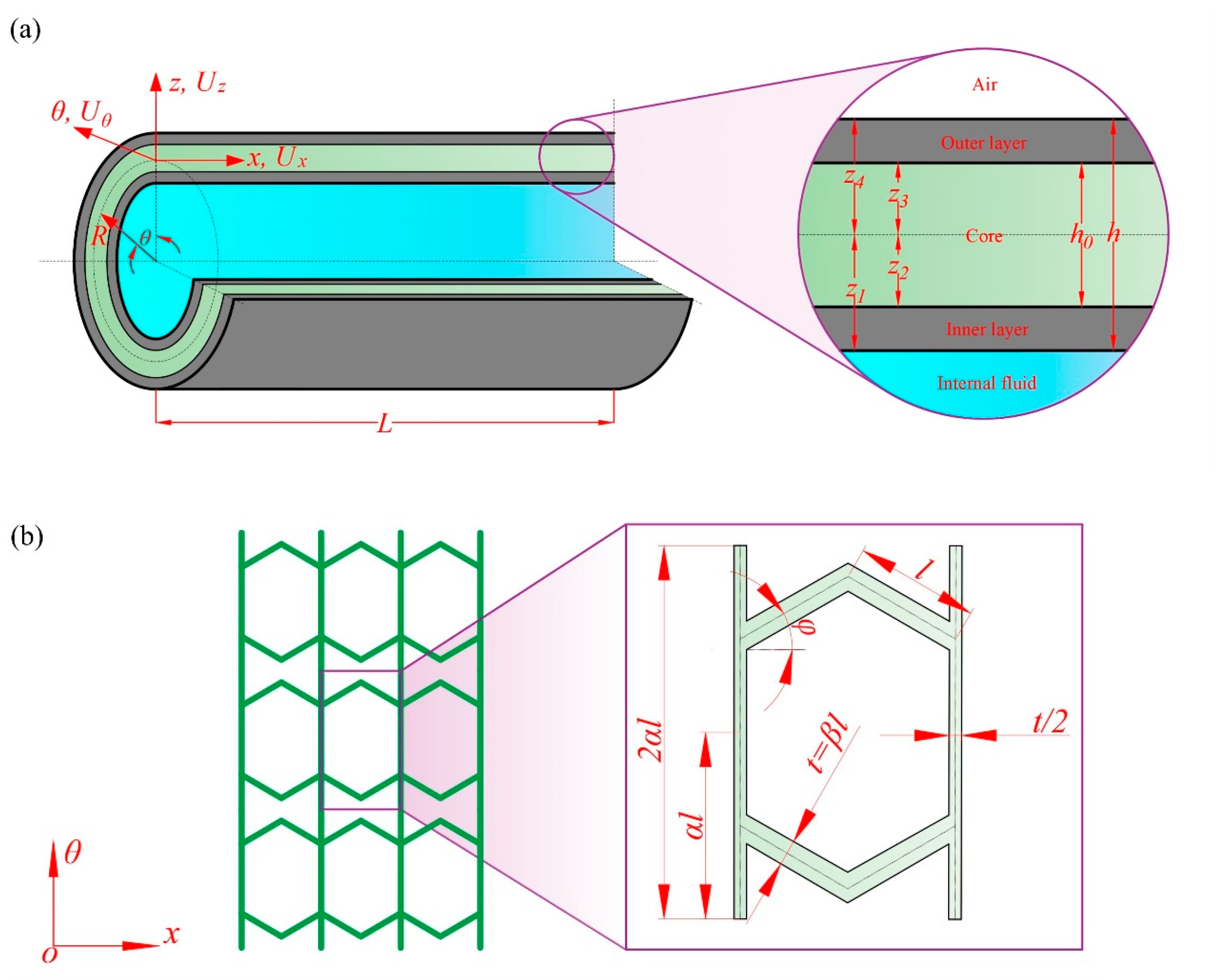
The NSFI consists of three distinct layers, with both the inner and outer layers composed of elastic and isotropic materials of equal thickness. The middle layer is characterized by a honeycomb structure featuring ZPR. Figure 1 shows the schematic sketch and the coordinate system of the NSFI, where the radius of middle surface is denoted as R, the thickness as h, and the length as L. An orthogonal coordinate system (z, x, and θ) is established at the middle surface. The deformations of the point at the middle surface of the insert wall are denoted as Ux, Uθ, and Uz, corresponding to the x, θ, and z directions, respectively. Coordinates (Zk, k = 1, 2, 3, 4) are defined for each layer as depicted in Figure 1a, with Z1 = h/2; Z2 = h0/2; Z3 = −h0/2; and Z4 = −h/2. Figure 1b depicts the ZPR honeycomb core and outlines the geometrical parameters of its unit cell. Here, φ is the internal angles, l represents the length of diagonal walls, 2αl represents the length of vertical walls, and t = βl represents the thickness of sloping walls. The parameters α and β correspond to the aspect ratio and the cell wall thickness ratios, respectively. The notations of variables in the NSFI are given as listed in Table 1.
For the sake of simplicity, it is assumed that the materials constituting the isotropic portions are uniform, characterized by an elastic modulus E, density ρt, and Poisson’s ratios μ. The material properties of the honeycomb structure are elaborated in Ref. [21]:
E x = E s c β 3 cos φ α ( sin 2 φ + β 2 cos 2 φ ) E θ = E s c β 2 cos φ μ x θ = μ θ x = 0 ρ = ρ c 2 + α β 2 α cos φ
where E s c and ρc are elastic modulus and density of raw materials used in the honeycomb core, respectively.
The basic membrane shell theory is applicable for analyzing the dynamics of a liquid-filled pipe wall in the context of long wave propagation. For long waves, the wavelength (λ) is much larger than the pipe radius (R, i.e., λ >> R), such that radial deformation is negligible, and bending stresses and moments have minimal influence on the overall dynamics. This approach thus emphasizes in-plane stresses (axial and circumferential) while neglecting bending effects, as noted by Tijsseling et al. [22]. Furthermore, the radial inertia of the flexible insert wall and the viscous friction of the internal fluid are not taken into account. Consequently, the forces exerted on the insert wall are depicted in Figure 2 and must adhere to the following conditions:
h N θ ( R h 2 ) P = 0 N x x I 2 u x t 2 = 0
where P is the internal fluid pressure distribution in z direction, Nx and Nθ are axial stress and circumferential stress of the insert wall, and I denotes the mass moment of inertia. The calculation of these parameters can be performed utilizing classical shell theory in conjunction with Hamilton’s principle, as elaborated in the work of Song et al. [21]:
N x = k = 1 3 z k z k + 1 σ x ( k ) R + z R d z = 1 R ( A 12 u x x A 13 w ) N θ = k = 1 3 z k z k + 1 σ θ ( k ) d z = ( A 23 u x x + A 24 w ) I = k = 1 3 z k z k + 1 ρ ( k ) d z = ρ t ( h h 0 ) + ρ h 0
where k = 1, 2, 3; k = 1 or 3 stands for the inner or outer layer; k = 2 stands for the core layer, and
A 12 = E R ( h h 0 ) μ 2 1 E x R h 0 A 13 = A 23 = E μ ( h h 0 ) μ 2 1 A 24 = 1 12 E μ 2 1 ( h 3 h 0 3 ) 1 R 3 1 12 E θ h 0 3 1 R 3 + E μ 2 1 ( h h 0 ) 1 R E θ h 0 1 R
By substituting Equation (3) into Equation (2), the equation for continuous motion of the internal fluid can be derived:
P = 2 2 R h A 23 u x x + A 24 w
By combining Equation (5) with the circumferential stress of the insert wall and subsequently eliminating the variable w, the following equation can be obtained:
N x A 13 A 24 2 R h 2 R P + A 12 A 13 A 23 A 24 1 R u x x = 0
Multiply both sides of the equation by the area of the insert wall, and Equation (6) can be rewritten as follows:
F x A 13 A 24 2 R h 2 R P A p + A 12 A 13 A 23 A 24 1 R u x x A p = 0
where Ap is the area of the internal fluid.
By taking the partial derivative of the above formula with respect to time, we obtain
F x t A 13 A 24 2 R h 2 R A p P t + A 12 A 13 A 23 A 24 1 R A p 2 u x x t = 0
According to the equation of continuous motion of fluid
1 E V P t + 1 A d A d t + 2 u f x t = 0
where Ev is the bulk modulus of the fluid in the rigid insert, uf is the longitudinal displacement of the fluid, A = π*R2 is the nominal area of the insert, and satisfy
1 A d A d t = 2 t ( w R )
Combining Equations (5), (9), and (10), the equation of continuous motion of the internal fluid can be rewritten as follows:
P t A 13 A 24 2 R E V 2 u x x t + E V 2 u f x t = 0
where E v is the corrected volume modulus of fluid, and can be expressed as
E V = E V 1 2 R h R 1 A 24 E V
The coupling of Equations (8) and (11) indeed reflects the mutual interaction between internal fluid and the insert wall. By integrating those equations and mutual boundary conditions, the FSI four-equation model of the NSFI can be derived:
P x + ρ f 2 u f t 2 = 0 P t A 13 A 24 2 R E V 2 u x x t + E V 2 u f x t = 0 F x x C 2 R A p 2 u x t 2 = 0 F x t A 13 A 24 2 R h 2 R A p P t + A 12 A 13 A 23 A 24 1 R A p 2 u x x t = 0
where
C 2 = ρ t ( h h 0 ) + ρ h 0 R
Assuming that the axial vibrations of both the insert wall and the internal liquid exhibit simple harmonic motion, it is feasible to obtain a simultaneous solution of the coupled fluid–structure system equations in wave form, based on linearized assumptions and periodic motion [23]. The resulting eigenvalues and mode shapes can be derived for pertinent fluid and structural variables without the necessity of employing finite element approximations. Consequently, the solution to the governing Equation (13) along the axial coordinate can be articulated as follows:
P = p ¯ e j w t = p ¯ ¯ e λ x e j w t F x = f ¯ e j w t = f ¯ ¯ e λ x e j w t u f = u ¯ f e j w t = u ¯ ¯ f e λ x e j w t u x = u ¯ x e j w t = u ¯ ¯ x e λ x e j w t
Equation (13) can be reformulated as follows:
u ¯ ¯ f = λ ω 2 ρ f p ¯ ¯ u ¯ ¯ x = R λ ω 2 C 2 A P f ¯ ¯ 1 + E V λ 2 ω 2 ρ f p ¯ ¯ + 2 A 13 A 24 h λ 2 ω 2 C 2 A P E V f ¯ ¯ = 0 1 A 12 A 13 A 23 A 24 λ 2 ω 2 C 2 f ¯ ¯ A 13 A 24 2 R h 2 R A p p ¯ ¯ = 0
From the expression above, we can derive a quartic equation in terms of λ:
λ 4 + α 1 λ 2 + β 1 = 0
where
α 1 = ω 2 C 2 A 13 A 23 A 24 A 12 + ρ f E V + A 13 2 A 24 2 2 R h R ρ f A 13 A 23 A 24 A 12
β 1 = ω 4 ρ f C 2 E V A 13 A 23 A 24 A 12
Therefore, the longitudinal wave numbers λ1 and λ2 for the insert wall and internal fluid considering the Poisson coupling can be determined:
λ 1 , 2 = 1 2 α 1 ± α 1 2 4 β 1
where λ = ± j λ 1 , ± j λ 2 .
The general solution of Equation (13) through linear superposition can be obtained:
f ¯ = A 1 e j λ 1 x + A 2 e j λ 1 x + A 3 e j λ 2 x + A 4 e j λ 2 x u ¯ x = N 1 A 1 e j λ 4 x A 2 e j λ 4 x + N 2 A 3 e j λ 2 x A 4 e j λ 2 x p ¯ = Z 1 A 1 e j λ 1 x + A 2 e j λ 1 x + Z 2 A 3 e j λ 2 x + A 4 e j λ 2 x u ¯ f = M 1 A 1 e j λ 1 x A 2 e j λ 1 x + M 2 A 3 e j λ 2 x A 4 e j λ 2 x
where Ai (i = 1, 2, 3, 4) are constants, and
N 1 = j λ 1 ω 2 C 2 R A p N 2 = j λ 2 ω 2 C 2 R A p Z 1 = A 24 A 13 2 R 2 R h 1 A p 1 A 12 A 13 A 23 A 24 λ 1 2 ω 2 C 2 Z 2 = A 24 A 13 2 R h 2 R 1 A p 1 A 12 A 13 A 23 A 24 λ 2 2 ω 2 C 2 M 1 = j λ 1 ω 2 ρ f Z 1 M 2 = j λ 2 ω 2 ρ f Z 2
In alignment with the definition of impedance for pipeline components, as outlined by Popkov et al. [20], the axial state variables at each end of the flexible inserts, in conjunction with the impedance matrix, are expressed in the following manner:
F x ( 0 ) F x ( L ) P ( 0 ) P ( L ) = Z 1 , 1 Z 1 , 7 Z 1 , 13 Z 1 , 14 Z 7 , 1 Z 7 , 7 Z 7 , 13 Z 7 , 14 Z 13 , 1 Z 13 , 7 Z 13 , 13 Z 13 , 14 Z 14 , 1 Z 14 , 7 Z 14 , 13 Z 14 , 14 U x ( 0 ) U x ( L ) A f U f ( 0 ) A f U f ( L )
where U f x = j ω u f x ; U x x = j ω u x x ; and Af is the cross-section of internal fluid.
Then the input mechanical impedance at the input end is obtained as
Z 1 , 1 = 1 ω M 2 cot λ 1 L M 1 cot λ 2 L M 1 N 2 M 2 N 1
The input mechanical impedance at the output end is obtained as
Z 7 , 7 = Z 1 , 1
The input acoustic impedances are
Z 13 , 13 = P ( 0 ) A f U f ( 0 ) = 1 ω A f Z 1 N 2 cot λ 1 L Z 2 N 1 cot λ 2 L M 1 N 2 M 2 N 1
Z 14 , 14 = Z 13 , 13
The transfer mechanical impedances are
Z 1 , 7 = 1 ω M 2 sin λ 1 L M 1 sin λ 2 L M 1 N 2 M 2 N 1
Z 7 , 1 = Z 1 , 7
The transfer acoustic impedances are
Z 13 , 14 = P ( 0 ) A f U f ( L ) = 1 ω A f Z 1 N 2 sin λ 1 L Z 2 N 1 sin λ 2 L M 1 N 2 M 2 N 1
Z 14 , 13 = Z 13 , 14
The input mechanical–acoustic impedances are
Z 1 , 13 = 1 ω A f N 2 sin λ 1 L N 1 sin λ 2 L M 1 N 2 M 2 N 1
Z 7 , 14 = Z 1 , 13
The transfer mechanical–acoustic impedances are
Z 1 , 14 = 1 ω A f N 2 sin ( λ 1 L ) N 1 sin ( λ 1 L ) M 1 N 2 M 2 N 1
Z 7 , 13 = Z 1 , 14
The input acoustic–mechanical impedances are
Z 13 , 1 = 1 ω Z 1 M 2 cot λ 1 L Z 2 M 1 cot λ 2 L M 1 N 2 M 2 N 1
Z 14 , 7 = Z 13 , 1
The transfer acoustic–mechanical impedances are
Z 13 , 7 = 1 ω Z 1 M 2 sin ( λ 1 L ) Z 2 M 1 sin ( λ 1 L ) M 1 N 2 M 2 N 1
Z 14 , 1 = Z 13 , 7

3. Model Verification

3.1. Numerical Verification

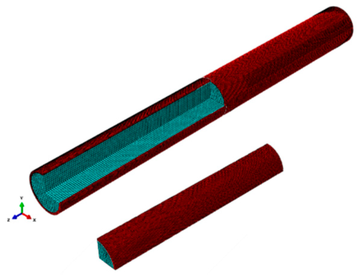
The FEM was utilized to validate the results derived theoretically regarding axial impedance and to juxtapose these findings with those from existing literature. Given that prior studies predominantly concentrate on isotropic uniform materials, the case of NSFI with h0 = 0 was selected for analysis. A harmonic response analysis of the fluid-filled flexible insert was performed using ABAQUS (Version 6.14) software, which involved the development of a finite element model encompassing both the insert wall and the internal fluid, as depicted in Figure 3. In this representation, the insert wall is indicated in red, while the internal fluid is illustrated in green.
The material characteristics and geometric specifications of the liquid-filled flexible insert are presented in Table 2. For straight flexible inserts, the relationship between the precision of discrete cells (λ) and the spatial step (Δx) adheres to Δx/λ ≤ 1/6 in grid division [24]. This ensures that each grid cell is adequately small relative to the precision, thereby preventing the omission of critical details during numerical computations and mitigating error accumulation that may arise from excessively coarse divisions. Such a rigorous methodology is crucial for improving the convergence and stability of simulation calculations, ultimately leading to more precise simulation results. The insert wall is modeled using solid elements C3D8R for meshing, with a granularity of 0.0025 m. The internal fluid is represented as an acoustic element, meshed with acoustic elements AC3D8 at a size of 0.005 m. As a result, the insert wall comprises 100,800 elements, while the fluid consists of 74,800 elements.
A direct steady-state dynamic analysis is performed to assess the harmonic response of the liquid-filled flexible insert. In this analysis, the lower frequency is set at 0.1 Hz, the upper frequency at 1000 Hz, and the number of points is established at 100. The fluid–structure interface is rigorously managed through ABAQUS TIE constraints, which enforce Kinematic continuity and dynamic equilibrium. The fluid boundary displacement equals solid displacement (ux = uf). This ensures the “no-slip” condition and continuity of motion. On the other hand, the pressure acting on the solid interface from the fluid is applied as a distributed load on the corresponding solid elements. Conversely, the motion of the solid boundary provides the boundary condition for the fluid domain.
The boundary conditions are defined as illustrated in Table 3, where the enclosed boundary condition for the internal fluid is characterized by an acoustic admittance set to zero. Acoustic impedance and acoustic admittance are reciprocal; thus, setting the admittance to zero corresponds to a rigid wall condition. In evaluating acoustic and mechanical–acoustic impedance, the internal fluid is subjected to a unit acoustic pressure, with the frequency response curve oriented axially. Similarly, for the assessment of mechanical and acoustic–mechanical impedance, an axial unit excitation force is applied to the insert wall, with its frequency response curve also aligned axially.
The finite element model solves the coupled fluid–structure system using the following governing equations:
ρ t 2 u x t 2 = σ   ( Structural   dynamics )
2 p 1 c 2 2 p t 2 = 0 , c = E v ρ f   ( Acoustic   wave   equation   for   fluid )
where σ is the stress tensor. These conditions are implemented via ABAQUS TIE constraints.
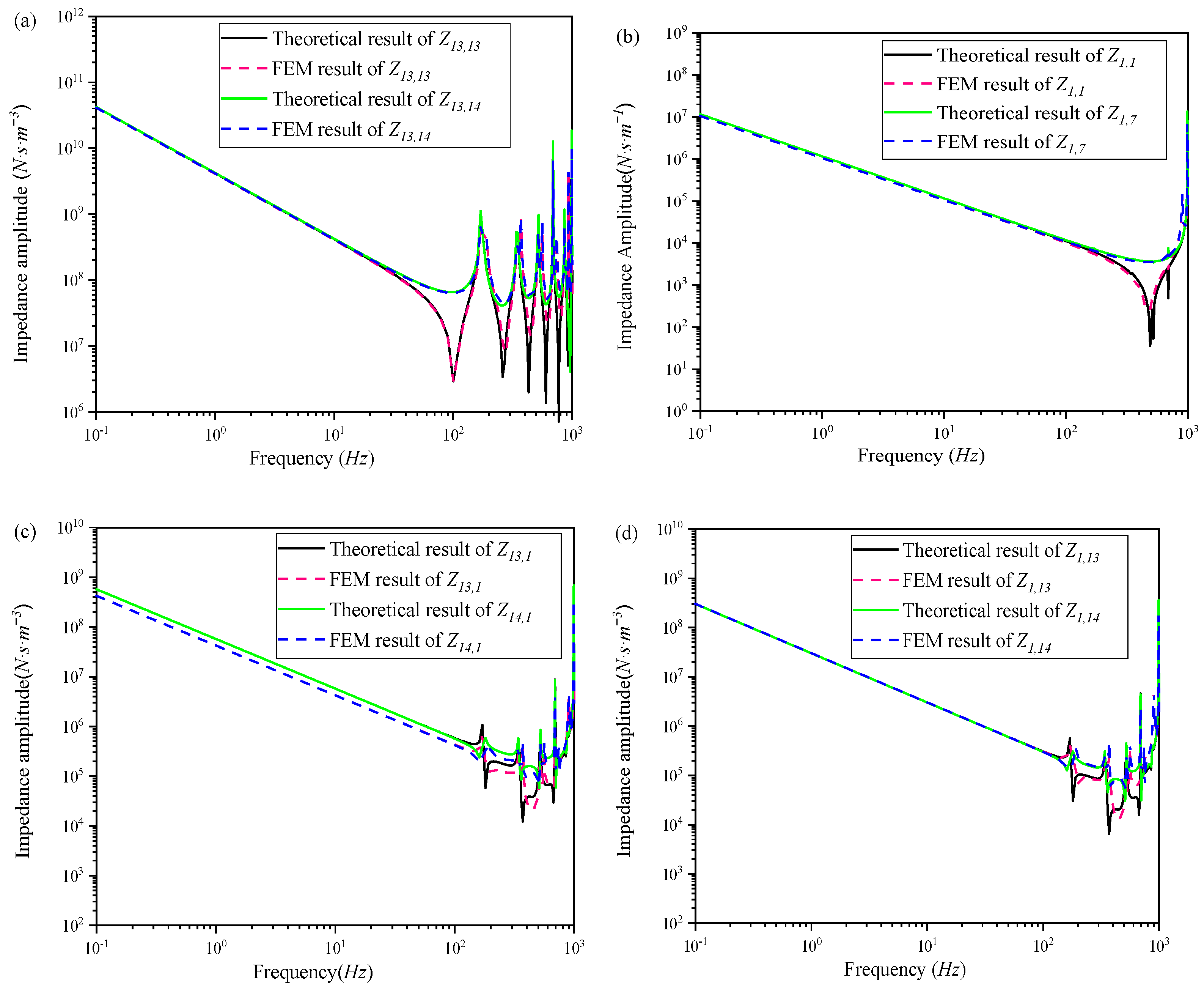
A comparison of the finite element method (FEM) results for the axial impedance of the flexible inserts with the theoretical outcomes is presented in Figure 4. Specifically, the amplitude–frequency curve of axial impedance obtained through FEM aligns closely with the theoretical calculations across the frequency range of 0.1 to 1000 Hz. Additionally, Figure 4 illustrates that for elastic and isotropic flexible inserts, the input acoustic impedance and input mechanical impedance initially display anti-resonance followed by resonance, whereas the transfer impedance exhibits resonance followed by anti-resonance. Moreover, the amplitude–frequency curve of the coupled impedance demonstrates an inverse relationship with the variations in acoustic and mechanical impedances. The frequency at which the minimum acoustic impedance of the elastic and isotropic flexible pipes occurs is approximately 100 Hz, while the minimum mechanical impedance is observed at around 450 Hz.
To validate the precision of the proposed methodology for evaluating the axial impedance of flexible inserts, a comparative analysis was conducted with findings from existing research. In the study conducted by Su et al. [24], the axial and transverse impedance matrices for isotropic flexible inserts were derived utilizing the Timoshenko beam model, incorporating considerations of Poisson coupling. The comparative analysis reveals that the input and transfer impedances calculated in the present study align closely with those documented in Su et al. [24], notwithstanding minor discrepancies observed at both low and high frequency ranges, as illustrated in Figure 5. The primary source of these discrepancies is attributed to the omission of the insert wall thickness’s impact on pipeline impedance characteristics in Su’s report. Su’s research posits that the internal fluid pressure within a thin-walled insert applies force to the neutral axis of the insert wall, based on an assumption that fails to account for the effects of the insert wall itself. This approach diverges from the methodology employed in the current study, which recognizes and incorporates the impact of the insert wall. Furthermore, the analyses of Figure 5 indicate that wall thickness plays a significant role in influencing both the input and transfer acoustic–mechanical impedances. When evaluating solely the acoustic and mechanical impedances of the flexible insert, without considering the coupled impedance, the effect of wall thickness may be overlooked.

3.2. Experiment Verification

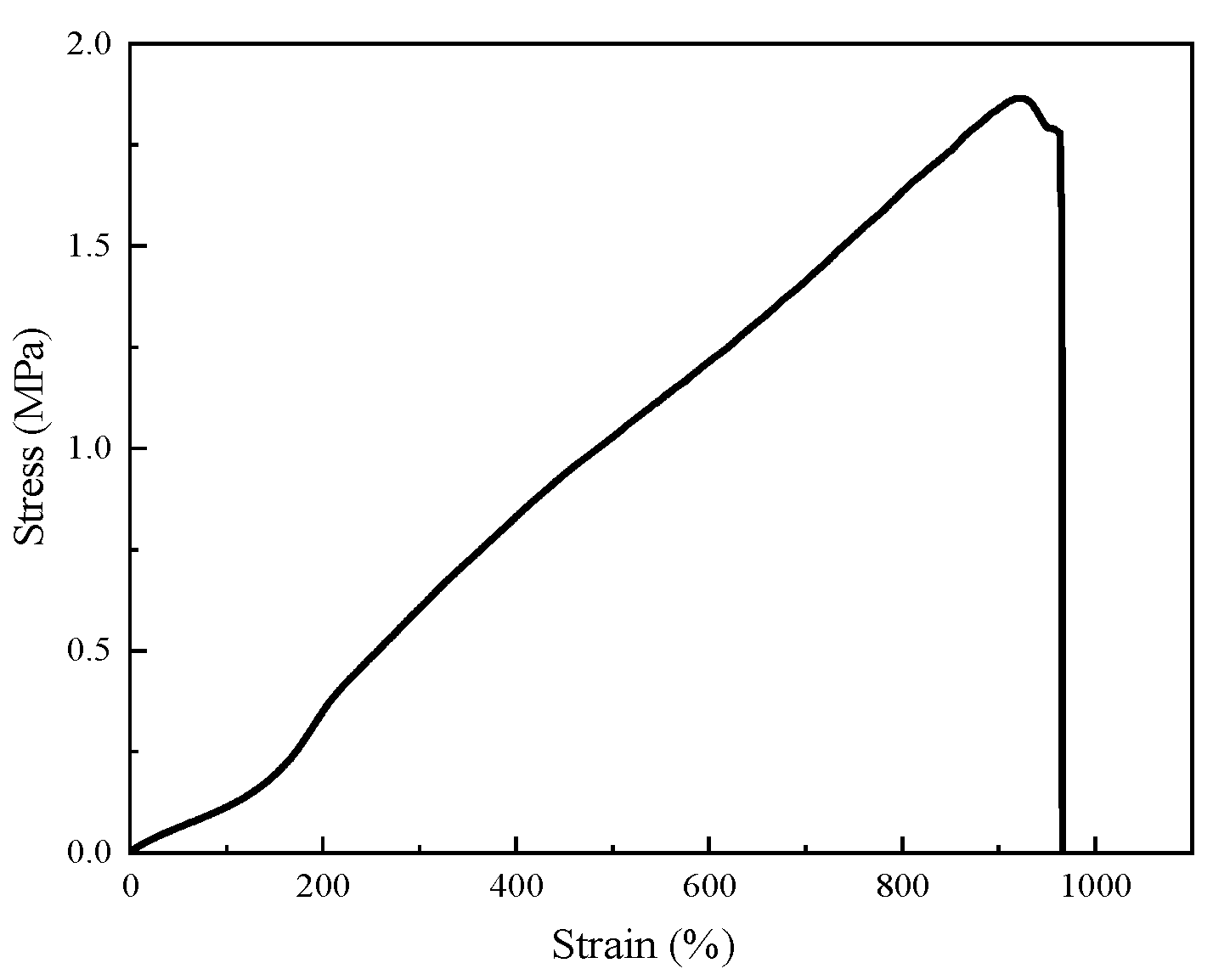
Given the intricate nature of the NSFI, conventional machining techniques are deemed insufficient. As a result, advanced additive layer manufacturing technology is utilized to produce the honeycomb core and flange, thereby enabling a more efficient and economical assessment of the dynamic characteristics. The honeycomb core (α = 0.5, β = 0.2, φ = 29.7°) and flange are fabricated in an integrated manner using a Stereolithography machine (3DSL-360Hi, Shanghai Digital Electronics Technology Co., Ltd., Shanghai, China) in conjunction with Wenext 7500 resin (WeNext Technology Co., Ltd., Shenzhen, China). The mechanical properties of Wenext 7500 resin are detailed in Table 4. Furthermore, both the inner and outer layers of the NSFI are composed of HY-E615 silica gel (Hongye Jie Technology Co., Ltd., Shenzhen, China), which is a dual-component material consisting of Part A, containing a catalyst, and Part B, which includes a curing agent. The stress–strain curve of HY-E615 is shown in Figure 6.
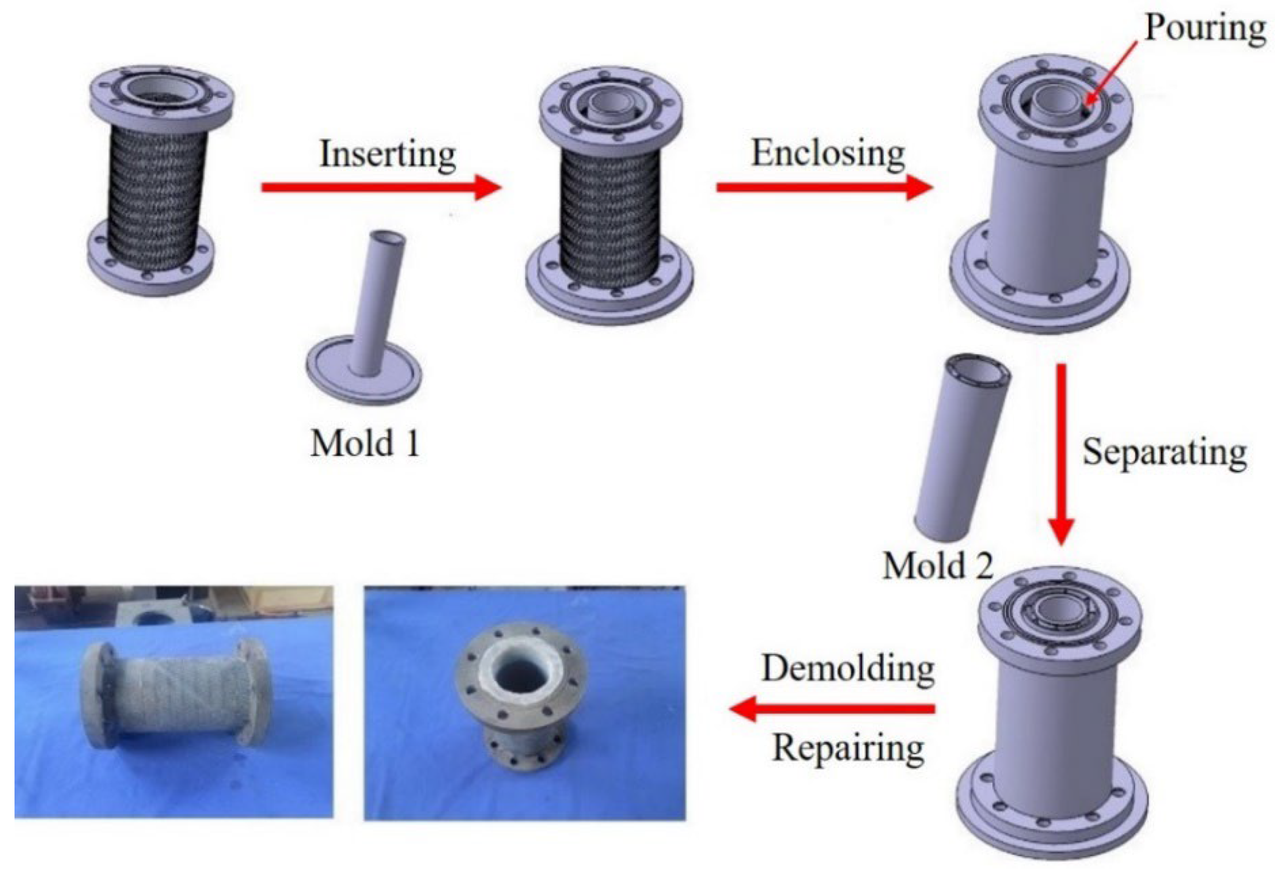
In the fabrication process of the NSFI, two distinct molds are utilized. Mold 1 serves the primary purpose of preventing the leakage of silica gel during the casting procedure, while Mold 2 is responsible for maintaining a consistent inner layer thickness of 2 mm. The comprehensive steps involved in this process are depicted in Figure 7 and are outlined as follows: (1) Inserting: Mold 1 is positioned within the assembled honeycomb core and flange; (2) Enclosing: a rigid thin plate is used to enclose the outer wall of the honeycomb core, securing it in place; (3) Pouring: after thoroughly mixing components A and B in equal ratios, the resultant mixture is introduced into the space between Mold 1 and the honeycomb core; (4) Separating: Mold 2 is then placed to ensure the uniformity of the inner layer’s thickness; (5) Demolding and Repairing: subsequent to a curing period of 30 min at 90 °C, the molds are removed, any necessary modifications are performed, and the NSFI is finalized.
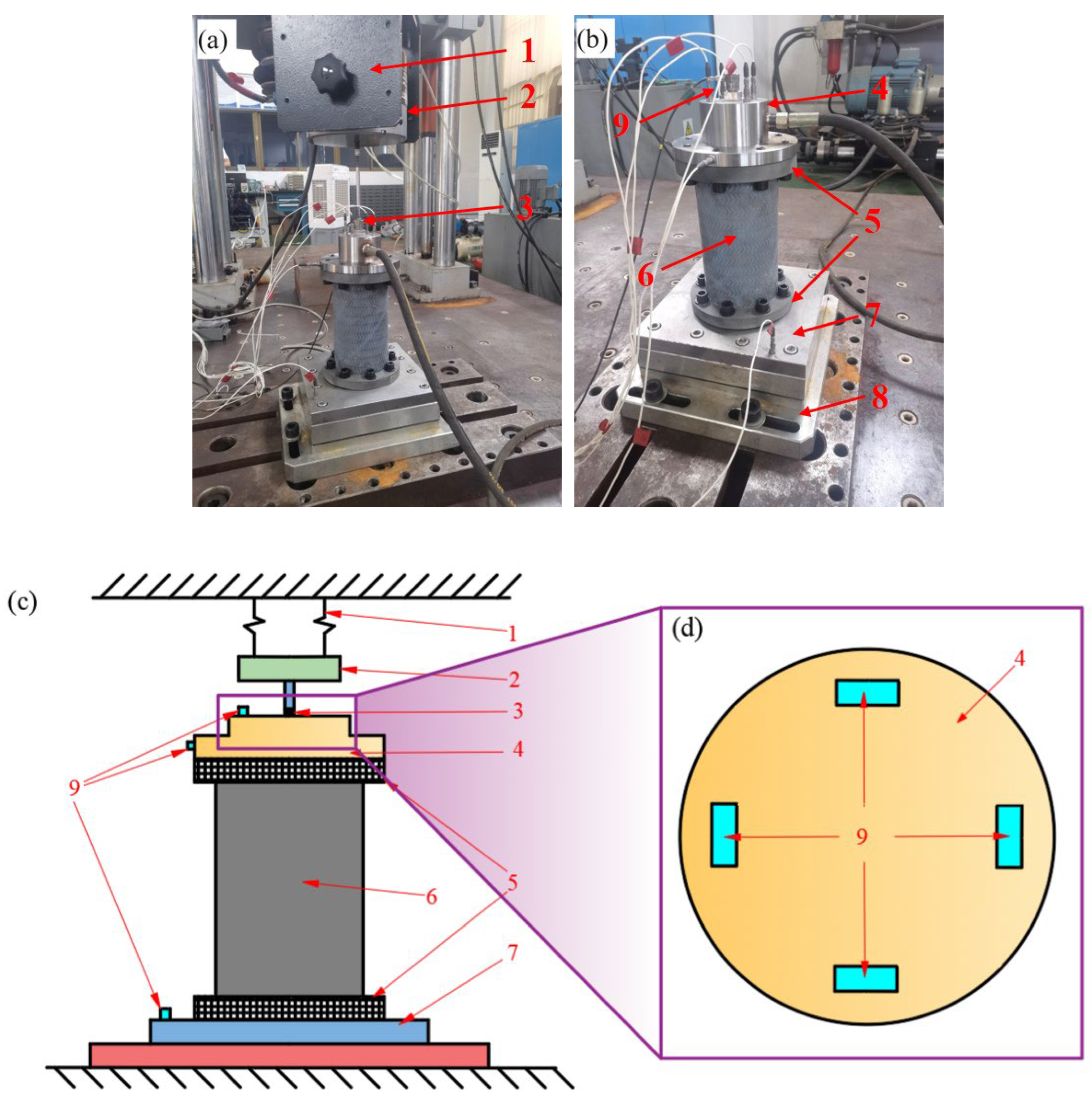
To evaluate the axial mechanical impedance of the NSFI with fluid, a variety of experimental configurations are employed, which include vibrators, force sensors, and dedicated measurement apparatus, as shown in Figure 8. The experimental system is designed to effectively manage the vibrational components that are orthogonal to the axis of the NSFI through the use of four vibration sensors positioned transversely. The configuration of these sensors, which is intended to regulate vibrations that are both perpendicular and rotational to the NSFI’s axis, is depicted in Figure 8d. The input and transfer impedances of the NSFI are derived from measurements of force and vibration velocity:
Im Z 1 , 1 ( ω ) = Im Z 1 , 1 m e a n s ( ω ) Im Z ( ω ) Re Z 1 , 1 ( ω ) = Re Z 1 , 1 m e a n s ( ω ) Re Z ( ω ) Z 1 , 1 ( ω ) = Re Z 1 , 1 ( ω ) 2 Im Z 1 , 1 ( ω ) 2 0.5
Im Z 1 , 7 ( ω ) = Im Z 1 , 7 m e a n s ( ω ) Im Z ( ω ) Re Z 1 , 7 ( ω ) = Re Z 1 , 7 m e a n s ( ω ) Re Z ( ω ) Z 1 , 7 ( ω ) = Re Z 1 , 7 ( ω ) 2 Im Z 1 , 7 ( ω ) 2 0.5
where Im Z 1,1 ( ω ) is the measured imaginary part of the input impedance, Re Z 1,1 ( ω ) is the measured real part of the input impedance, Im Z ω is the imaginary part of the input impedance of the measurement rigs, Re Z ω is the real part of the input impedance of the measurement rigs, Im Z 1,7 ( ω ) is the measured imaginary part of the transfer impedance, and Re Z 1,7 ( ω ) is the measured real part of the transfer impedance.
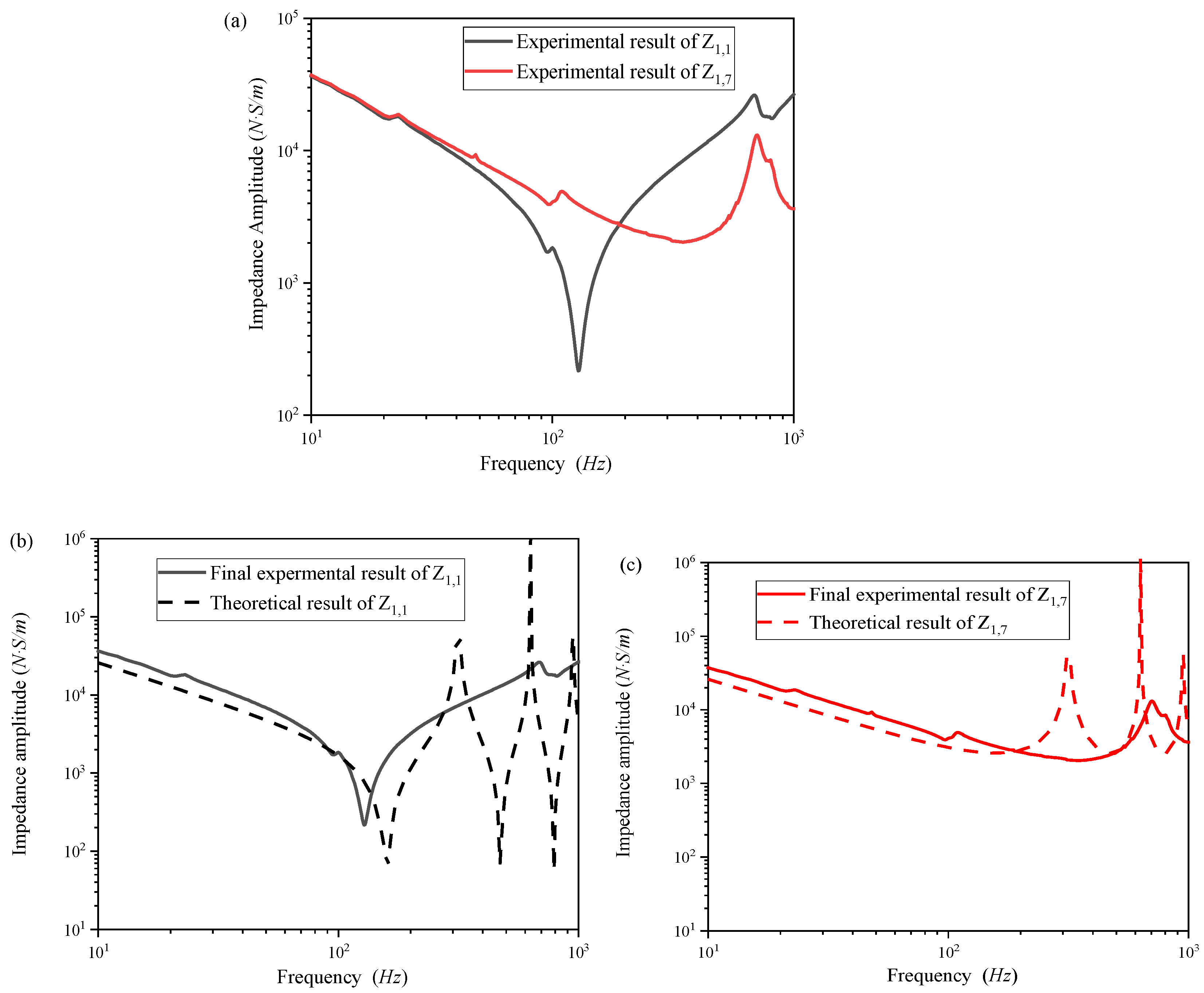
Figure 9 presents the experimental findings regarding the axial input and transfer mechanical impedance of the experimental system under no-load conditions. A comparative analysis of the final experimental results for axial mechanical impedance against theoretical predictions reveals several significant insights. In the low-frequency range (0–100 Hz), the input and transfer mechanical impedance amplitudes of the NSFI exhibit relatively minor deviations from the theoretical models. Conversely, substantial deviations are noted in the high-frequency range (100–1000 Hz). The experimentally determined anti-resonance frequency of the NSFI is 128 Hz, whereas theoretical calculations indicate an anti-resonance frequency of 159 Hz, resulting in a considerable relative error. This divergence between experimental outcomes and theoretical expectations can be attributed to several factors. (1) Integration of Components: The integration of the honeycomb core and flanges via 3D printing incorporates the impedance of the flanges into the experimental measurements, which may not be considered in theoretical models. This integration could modify the dynamic response of the NSFI, particularly at elevated frequencies where structural characteristics exert greater influence. (2) Material and Structural Variations: Theoretical models generally presume that the NSFI comprises a honeycomb core and two rubber elastic surface layers of equal thickness. In practice, the pores of the honeycomb core are filled with silica gel, and the uniformity of the rubber layers’ thickness cannot be assured. Such variations may introduce discrepancies in mechanical impedance, particularly concerning the distribution and density of materials, which impact vibration damping and stiffness. (3) Model Limitations: The beam model employed in theoretical calculations typically has restricted applicability at higher frequency ranges. The experimental system in Figure 8 and Figure 9 characterizes the intrinsic axial impedance of the NSFI, a critical parameter for vibration reduction in pipelines. Future work will validate its performance in a full ship pipeline prototype, but the observed low impedance here suggests strong potential for energy absorption in system-level applications.

4. Results and Discussion

The theoretical formula was implemented in a Matlab program to calculate the axial impedance of the NSFI. This section investigates the influence of varying the geometric dimensions of the NSFI and the structural parameters of the honeycomb core on the dynamic characteristics of the NSFI. Table 5 enumerates the geometric dimensions of the NSFI, the structural parameters of the honeycomb core, and the material properties employed in the parametric analysis. All results, unless specified otherwise, are based on the data provided in Table 5. Figure 10, Figure 11, Figure 12 and Figure 13 delineate the influence of the structural parameters of the honeycomb core on the dynamic characteristics of the NSFI. Figure 14 and Figure 15 illustrate the impact of geometrical parameters on the impedance of the NSFI.
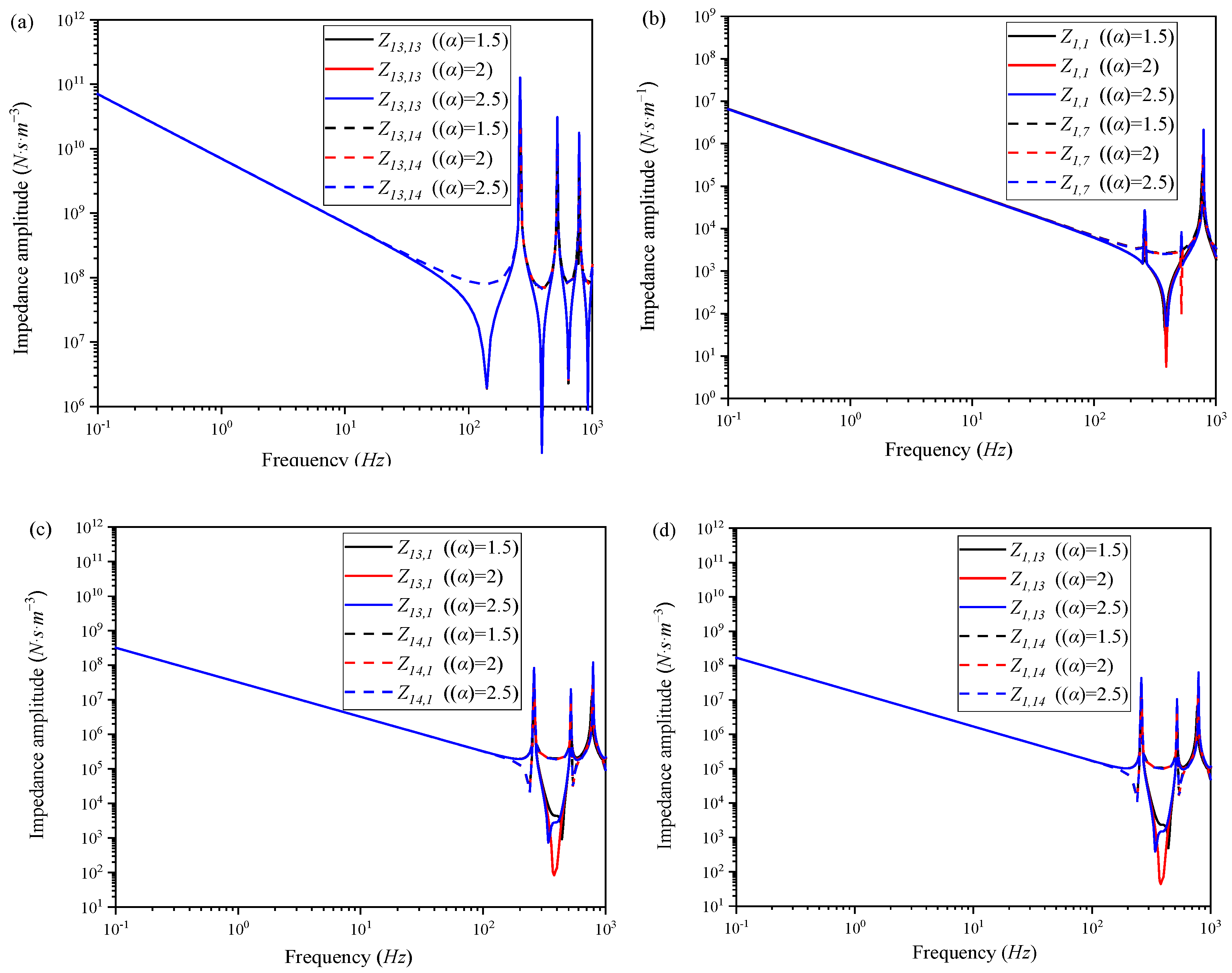
Figure 10 illustrates that α has a negligible effect on both acoustic and mechanical impedance. However, it significantly affects the coupling impedance. An increase in α correlates with a marked reduction in the first anti-resonance frequency for both input mechanical–acoustic and acoustic–mechanical impedances. Figure 11 demonstrates the effect of β on the impedance of the fluid-filled NSFI, revealing that both resonance and anti-resonance frequencies increase as β rises. In the low-frequency range, the magnitudes of acoustic and mechanical impedances increase with β, while the magnitudes of mechanical–acoustic and acoustic–mechanical impedances decrease. The elevation of β contributes to an overall increase in the stiffness of the NSFI [21]. At lower frequencies, enhanced stiffness results in a more rigid NSFI, producing a greater reaction force even with minimal displacements, thereby augmenting mechanical impedance. Additionally, as stiffness increases, the NSFI exhibits a higher acoustic propagation speed, leading to an elevated acoustic impedance.
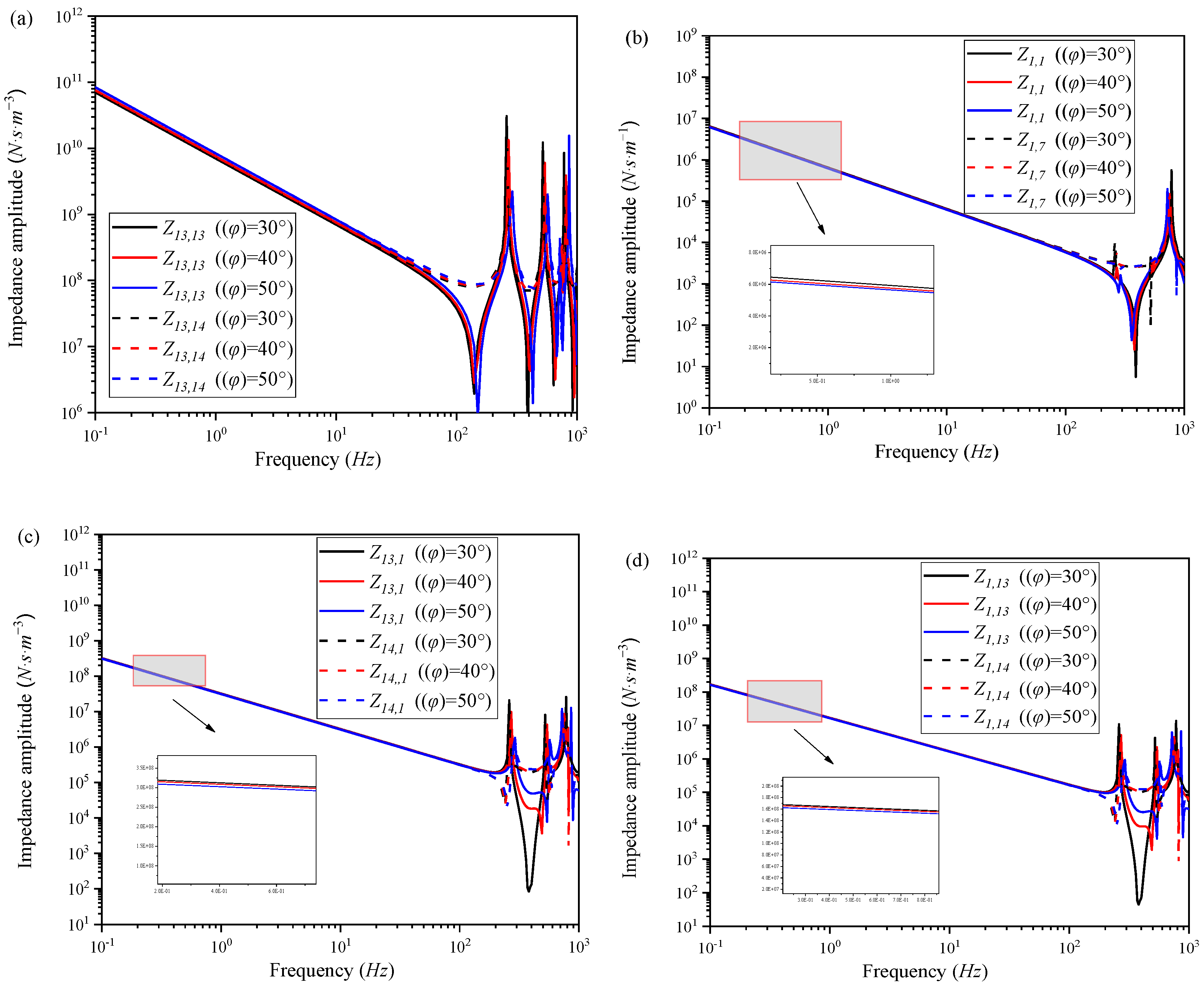
Figure 12 explores the effect of φ on impedance, revealing that an increase in φ leads to a decrease in the resonance and anti-resonance frequencies of mechanical impedance, whereas those of acoustic impedance, acoustic–mechanical, and mechanical–acoustic impedance escalate. Furthermore, with an increase in φ, the magnitude of the acoustic impedance increases, while the magnitudes of mechanical impedance, acoustic–mechanical impedance, and mechanical–acoustic impedance decrease in the low-frequency range. Figure 13 investigates the effect of h0, demonstrating that an increase in h0 leads to a decrease in the resonance and anti-resonance frequencies of mechanical impedance. Conversely, the frequencies for acoustic impedance, acoustic–mechanical, and mechanical–acoustic impedance increase. Within the low-frequency domain, a progressive increase in h0 results in a higher magnitude of acoustic impedance, while the magnitudes for mechanical, acoustic–mechanical, and mechanical–acoustic impedance decrease. The increased φ and h0 can weaken the core layer’s enhancement effect on the NSFI’s global rigidity, leading to the decline of the global bending rigidity of the NSFI. At this point, the enhancement effect of the core layer as the upper and lower panel spacing on overall bending stiffness of the NSFI is weakened, resulting in the reduction in the overall bending stiffness and mechanical impedance of the NSFI. In addition, the density of the elastic and isotropic materials is less than that of this NSFI’s core. When h is given a definite value, an increase in core thickness h0 leads to the reduction in the inner and outer layer thickness. In other words, an increase in h0 will augment the overall mass of the NSFI, leading to an increase in both acoustic propagation speed and acoustic impedance.
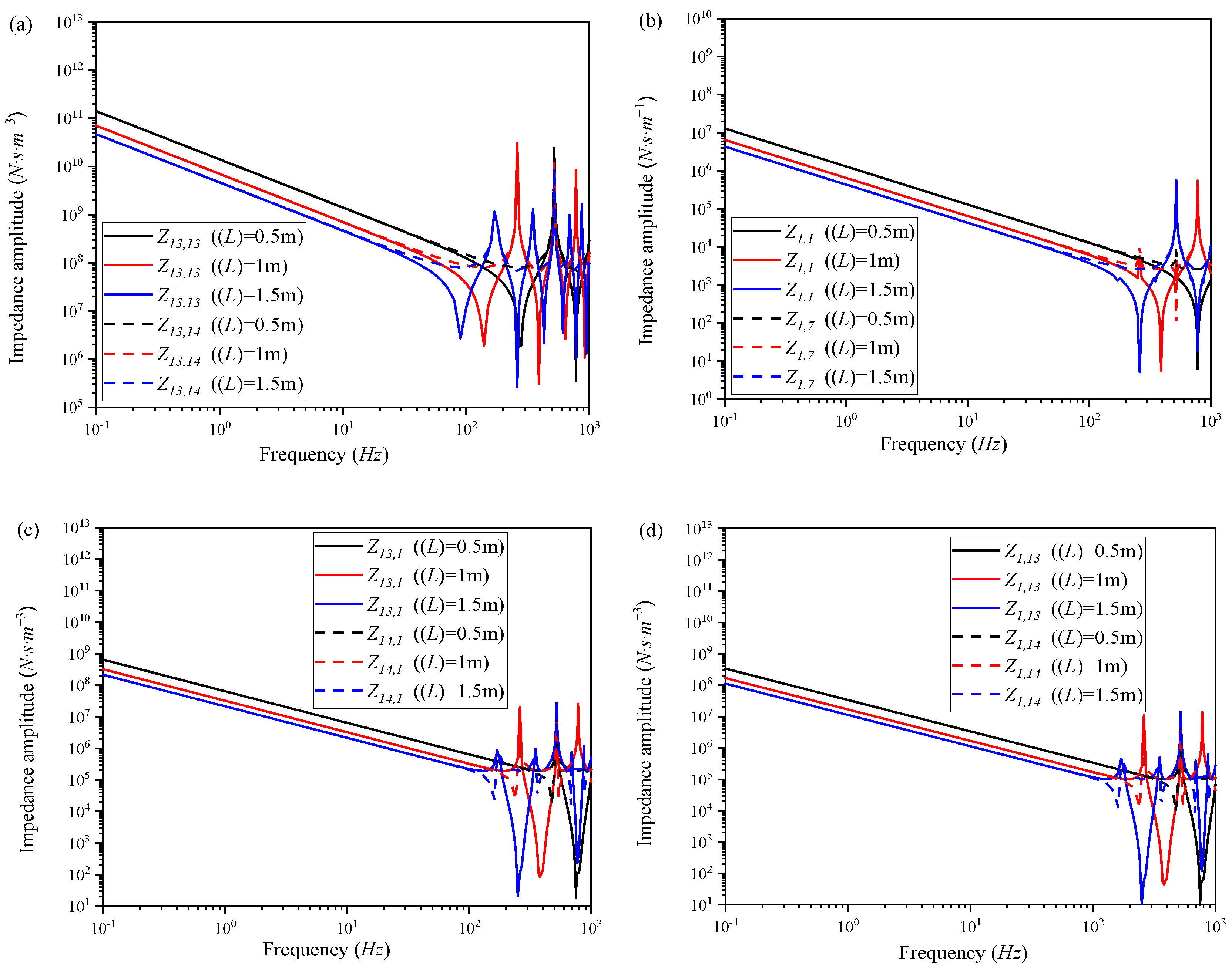
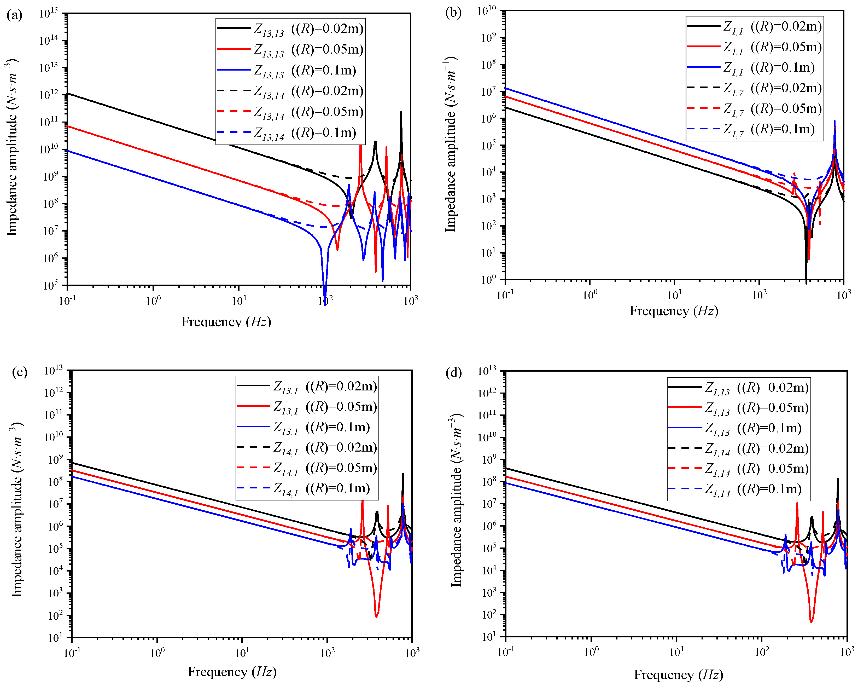
Figure 14 illustrates the impact of L on the axial impedance of the fluid-filled NSFI. The data presented in the graph indicates that an increase in L corresponds to a reduction in both the resonance and anti-resonance frequencies. Additionally, within the low-frequency range, the amplitude of the impedance diminishes with an increase in L. As shown in Figure 15, an increase in R is associated with a decrease in the resonance and anti-resonance frequencies for acoustic, mechanical–acoustic, and acoustic–mechanical impedance, whereas the frequencies for mechanical impedance remain relatively unchanged. Additionally, in the low-frequency range, an increase in R results in a decrease in the magnitudes of acoustic, mechanical–acoustic, and acoustic–mechanical impedance, while the magnitude of mechanical impedance experiences an increase.
In fluid-filled pipelines, the resistance induced by viscosity generates a frictional interaction between the internal fluid and the pipe wall, a phenomenon referred to as friction coupling [25,26]. Sudden alterations in the direction of the fluid at specific fittings lead to what is known as connection coupling. In the case of bent pipes with non-circular cross-sections, the forced redirection of the fluid results in pressure fluctuations, which produce a “straightening” effect identified as Bourdon coupling. Generally, in scenarios characterized by medium to low frequencies, the influence of friction coupling on the dynamic response of pipeline systems is minimal and frequently overlooked. However, at elevated frequencies, the formation of a boundary layer engenders a “collective state”, thereby complicating the relationship between fluid friction and vibration frequency considerably. Friction coupling and Poisson coupling are fundamental behaviors within pipeline systems that significantly affect overall system dynamics, while connection coupling and Bourdon coupling primarily influence localized regions. The effect of friction coupling on the response of the pipeline system is relatively minor, whereas connection coupling and Poisson coupling exert a more pronounced influence on the system’s dynamics, with Bourdon coupling impacting only the bends. Therefore, in straight pipelines devoid of branches, both connection and Bourdon couplings are absent, rendering Poisson coupling the predominant factor in the fluid–structure interaction within the pipeline system.
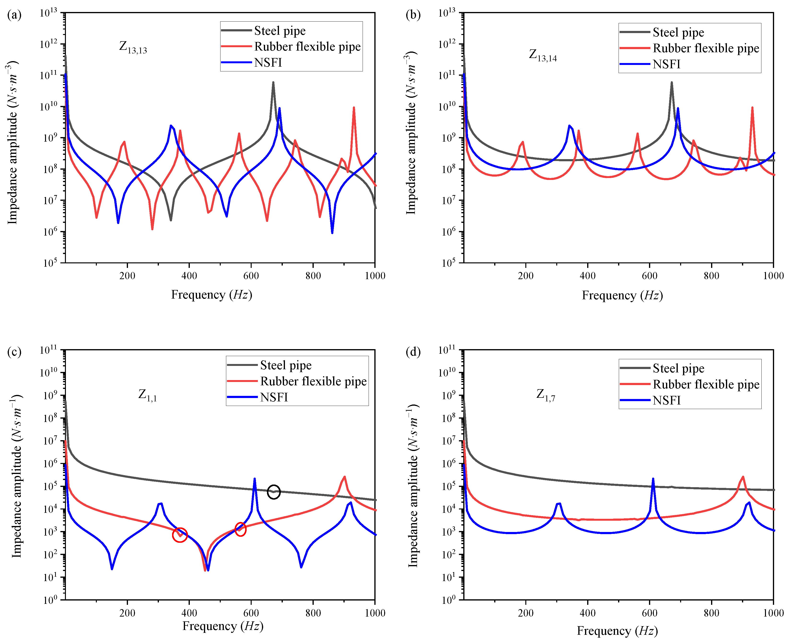
Figure 16 presents a comparative analysis of the impedance characteristics of the NSFI with those of steel pipes and rubber flexible pipes as the parameter h0 approaches h. It is observed that within the low-frequency range, the magnitudes of both acoustic and mechanical impedance for steel pipes surpass those of both the rubber flexible pipe and the NSFI. Notably, while the acoustic impedance of the rubber flexible pipe is lower than that of the NSFI, its mechanical impedance is comparatively higher. Furthermore, the resonance and anti-resonance frequencies associated with steel pipes are elevated relative to those of both the rubber flexible pipe and the NSFI. In the case of rubber flexible pipes, the resonance and anti-resonance frequencies for acoustic impedance are lower than those of the NSFI, whereas the mechanical impedance frequencies are higher. Additionally, the magnitude-frequency curves for mechanical impedance of both steel and rubber flexible pipes display several minor spikes, which can be attributed to the FSI characteristics between the pipe wall and the internal fluid [27]. Moreover, compared to rigid pipelines, the differences in density and sound speed between the walls of flexible inserts and the internal fluids are less marked, enhancing the acoustic vibration coupling effect. The vibrations of the insert wall induce vibrations in the internal fluid, while the pulsations of the internal fluid result in radial deformation and axial changes in the pipe wall, as noted by Tijsseling et al. [28]. This phenomenon is particularly pronounced in elbow-shaped flexible conduits, which significantly affects the lateral vibrations of the pipeline. As depicted in Figure 16, the absence of spikes in the NSFI curve as h0 approaches h suggests that the structure and the longitudinal waves of the fluid operate independently, with no occurrence of Poisson coupling. Despite theoretical frameworks that conceptualize the honeycomb core as an anisotropic homogeneous shell structure, the NSFI presents an innovative solution to the challenges posed by Poisson coupling in piping systems. It is important to note that honeycomb cores are typically regarded as homogeneous orthotropic materials, as their equivalent properties can be predicted irrespective of the complexity of their internal structures.

5. Conclusions

In the paper, a NSFI was developed, featuring a distinctive three-layer configuration comprising elastic inner and outer layers, along with a honeycomb core exhibiting a zero Poisson’s ratio, which is intended to effectively isolate and/or mitigate vibrations and noise on piping system. An effective theoretical prediction of dynamic characteristics for the fluid-filled NSFI was derived based on the FSI four-equation model. The theoretical predictions were subsequently validated through finite element analysis and experimental results, alongside comparisons with existing literature. The primary conclusions are listed as follows:
(1) The results of the parametric analysis show that various geometric parameters exert differential influences on axial impedance, thus facilitating the customization of impedance characteristics through parameter adjustments. For example, the parameter α has a negligible effect on the impedance of the fluid-filled NSFI. In contrast, an increase in the parameter β correlates with an elevation in both the resonant and anti-resonant frequencies of the pipeline, resulting in increased acoustic and mechanical impedance at lower frequencies. Concurrently, both mechanical–acoustic and acoustic–mechanical impedances exhibit a decline. Additionally, an increase in the parameter φ leads to higher resonant and anti-resonant frequencies of acoustic impedance, while the corresponding frequencies for mechanical impedance decrease.
(2) The amplitude–frequency curves of mechanical impedance for steel pipes and rubber flexible pipes display several minor spikes, attributed to the FSI characteristics between the pipe wall and the internal fluid. However, as h0 approaches h, the amplitude–frequency curve of the NSFI’s mechanical impedance is devoid of these spikes, indicating that the longitudinal waves within the structure and the fluid operate independent, with no Poisson coupling occurring. This observation suggests a novel approach for mitigating Poisson coupling effects.
It should also be noted that the FSI four-equation model is founded upon a beam model. Beam models may oversimplify the intricate interactions and dynamic behaviors of materials and structures, resulting in inaccuracies in predicting anti-resonance frequencies and impedance amplitudes at elevated frequencies. In future work, a more sophisticated model that incorporates the actual material properties and structural details of the NSFI is necessary, including the effects of 3D printing integration and the actual material distribution within the honeycomb core. Furthermore, adjustments to the experimental setups may be warranted to better isolate the characteristics of the NSFI from the contributions of the measurement apparatus, thereby ensuring more precise impedance measurements.
Author Contributions

Conceptualization, L.S., L.C., Z.Y. and X.H.; methodology, L.S.; software, Z.H.; validation, L.S., Y.L., Y.Z. and L.C.; formal analysis, L.S.; investigation, L.S.; resources, L.C., X.X. (Xinjiang Xiang) and Y.L.; data curation, F.L.; writing—original draft preparation, L.S.; writing—review and editing, Y.L.; visualization, X.X. (Xiaozhou Xu); supervision Y.Z.; project administration, X.X. (Xinjiang Xiang). All authors have read and agreed to the published version of the manuscript.

Funding

This research was funded by the National Natural Science Foundation of China, grant number 62303419; the National Natural Science Foundation of China, grant number 52302452; the Natural Science Foundation of Jiangsu Province, grant number BK20230326; Zhejiang Provincial Natural Science Foundation, grant number LQ24F030024; Zhejiang Province Key R&D Program, grant number 2023C03015.

Data Availability Statement

Data will be made available on request.

Conflicts of Interest

Authors Feng Li and Zhihua Huang are employed by the company Yongkang Valid Technology Co., Ltd. The remaining authors declare that the research was conducted in the absence of any commercial or financial relationships that could be construed as a potential conflict of interest.

References

  1. Lu, Y.; Li, K.; Lin, R.; Wang, Y.; Han, H. Intelligent Layout Method of Ship Pipelines Based on an Improved Grey Wolf Optimization Algorithm. J. Mar. Sci. Eng. 2024, 12, 1971. [Google Scholar] [CrossRef]
  2. Qi, L.; Yu, H.; Tang, H.; Zou, M. Study of the influence of added water and contained water on structural vibrations and acoustic radiation using different dynamic modeling methods. J. Hydrodyn. 2023, 35, 1157–1167. [Google Scholar] [CrossRef]
  3. Chen, L.; Zuo, Y.; Yang, D. Human-induced noise study for cruise: Numerical analysis and experimental validation. Ocean Eng. 2023, 286, 115498. [Google Scholar] [CrossRef]
  4. Zhu, H.; Wu, J. A Study on the Vibration Analysis of Thick-Walled, Fluid-Conveying Pipelines with Internal Hydrostatic Pressure. J. Mar. Sci. Eng. 2023, 11, 2338. [Google Scholar] [CrossRef]
  5. Park, M.; Yeo, S.; Choi, J.; Lee, W. Review of noise and vibration reduction technologies in marine machinery: Operational insights and engineering experience. Appl. Ocean Res. 2024, 152, 104195. [Google Scholar] [CrossRef]
  6. Wang, Y.; Tang, Y.; Yang, T. Nonlinear mechanic analysis of a composite pipe conveying solid-liquid two-phase flow. Appl. Ocean Res. 2024, 144, 103905. [Google Scholar] [CrossRef]
  7. Li, F.; Guo, H.; Shen, W.; Gu, H.; Liu, R.; Zhao, C.; Li, X. Experimental exploration of unpowered propellers for vortex-induced vibration suppression of flexible riser. Ocean Eng. 2022, 266, 112968. [Google Scholar] [CrossRef]
  8. Liang, F.; Xu, W.; Chen, Z. Flexural-torsional vibration reduction of an eccentric phononic crystal pipe conveying fluid. J. Fluids Struct. 2023, 120, 103904. [Google Scholar] [CrossRef]
  9. Kandasamy, R.; Cui, F.; Townsend, N.; Foo, C.; Guo, J.; Shenoi, A.; Xiong, Y. A review of vibration control methods for marine offshore structures. Ocean Eng. 2016, 127, 279–297. [Google Scholar] [CrossRef]
  10. Zhou, X.; Zhang, S.; Lin, W. Sound radiation characteristics analysis for the honeycomb reinforced laminated structures with viscoelastic material fillers through the asymptotic homogenous method. Compos. Struct. 2020, 245, 112266. [Google Scholar] [CrossRef]
  11. Tan, H.; He, Z.; Li, E.; Tan, X.; Cheng, A.; Li, Q. Energy absorption characteristics of three-layered sandwich panels with graded re-entrant hierarchical honeycombs cores. Aerosp. Sci. Technol. 2020, 106, 106073. [Google Scholar] [CrossRef]
  12. Huang, J.; Zhang, Q.; Scarpa, F.; Liu, Y.; Leng, J. Bending and benchmark of zero Poisson’s ratio cellular structures. Compos. Struct. 2016, 152, 729–736. [Google Scholar] [CrossRef]
  13. Wang, H.; Chen, Y.; Xi, Z.; Song, L.; Kong, X.; Shen, X. Forced vibration of sandwich pipes with zero Poisson’s ratio honeycomb core under moving pressure. Int. J. Press. Vessel. Pip. 2023, 202, 104876. [Google Scholar] [CrossRef]
  14. Tijsseling, A. Fluid-structure Interaction and Cavitation in a Single-elbow Pipe System. J. Fluids Eng. 1996, 10, 395–420. [Google Scholar] [CrossRef]
  15. Vardy, A.; Fan, D.; Tijsseling, A. Fluid-structure interaction in a T-piece pipe. J. Fluid. Struct. 1996, 10, 763–786. [Google Scholar] [CrossRef]
  16. Dai, H.; Wang, L.; Qian, Q. Vibration analysis of three-dimensional pipes conveying fluid with consideration of steady combined force by transfer matrix method. Appl. Math. Comput. 2012, 266, 2453–2464. [Google Scholar] [CrossRef]
  17. Li, Q.; Yang, D. Vibration and Sound Transmission Performance of Sandwich Panels with Uniform and Gradient Auxetic Double Arrowhead Honeycomb Cores. Shock Vib. 2019, 2019, 6795271. [Google Scholar] [CrossRef]
  18. Li, S.; Liu, G.; Kong, W. Vibration analysis of pipe conveying fluid by transfer matrix method. Nucl. Eng. Des. 2014, 266, 78–88. [Google Scholar] [CrossRef]
  19. EI-Sayed, T.; EI-Mongy, H. Free vibration and stability analysis of a multi-span pipe conveying fluid using exact and variational iteration methods combined with transfer matrix method. Appl. Math. Model. 2019, 71, 173–193. [Google Scholar] [CrossRef]
  20. Popkov, V. Defining Dynamic properties (Impedances) of the flexible inserts with fluid. Acta Acust. 2012, 98, 870–883. [Google Scholar] [CrossRef]
  21. Song, L.; Wang, T.; Yin, Z.; Shen, X.; Wang, H.; Chao, Y. Free Vibrational Characteristics of Sandwich Cylindrical Shells Containing a Zero Poisson's Ratio Cellular Core. J. Vib. Eng. Technol. 2023, 12, 1603–1620. [Google Scholar] [CrossRef]
  22. Tijsseling, A. Fluid-Structure Interaction in Case of Waterhammer with Cavitation. Ph.D. Thesis, Delft University of Technology, Delft, The Netherlands, 1993. [Google Scholar]
  23. Lesmez, M.; Wiggert, D.; Hatfield, D. Modal analysis of vibrations in liquid-filled piping system. J. Fluids Eng. 1990, 112, 311–318. [Google Scholar] [CrossRef]
  24. Su, M.; Sun, Y.; Wang, S.; Hao, X. Theoretical study on axial coupling impedance of fluid-filled flexible pipes. J. Ship Mech. 2021, 25, 360–369. (In Chinese) [Google Scholar] [CrossRef]
  25. Liu, Z.; Wu, G.; Wang, H.; Zhang, J.; Tang, J.; Li, X. Investigation on method of characteristics and semi-implicit method for pressure linked equations algorithms for water hammer based on unsteady friction. J. Hydrodyn. 2024, 36, 1155–1166. [Google Scholar] [CrossRef]
  26. Wang, J.; Fan, D.; Lin, K. A review on flow-induced vibration of offshore circular cylinders. J. Hydrodyn. 2020, 32, 415–420. [Google Scholar] [CrossRef]
  27. Wu, J.; Sun, Y.; Su, M.; Zhu, H. Fluid-structure interaction and band gap analysis of periodic composite liquid-filled pipe. Compos. Struct. 2023, 304, 116444. [Google Scholar] [CrossRef]
  28. Tijsseling, A.; Lambert, M. Skalak’s extend theory of water hammer. J. Sound Vib. 2008, 310, 718–728. [Google Scholar] [CrossRef]
Figure 1. (a) Schematic sketch and the coordinate system of the NSFI; (b) geometrical parameters of ZPR honeycomb core.
Jmse 13 01515 g001
Figure 2. Force diagram of the flexible inserts.
Jmse 13 01515 g002
Figure 3. Finite element model of the fluid-filled insert.
Jmse 13 01515 g003
Figure 4. Comparison of axial impedance of the flexible inserts: FEM results vs. theoretical results. (a) Acoustic impedances (b) Mechanical impedances (c) Acoustic-mechanical impedances (d) Mechanical-acoustic impedances.
Jmse 13 01515 g004
Figure 5. Comparison of axial impedance of the flexible inserts: theoretical results (considering wall thickness) vs. Ref. [24]. (a) Acoustic impedances (b) Mechanical impedances (c) Acoustic-mechanical impedances (d) Mechanical-acoustic impedances.
Jmse 13 01515 g005
Figure 6. The stress–strain curve of HY-E615.
Jmse 13 01515 g006
Figure 7. Production process flowchart of the NSFI.
Jmse 13 01515 g007
Figure 8. The experimental system for mechanical impedance analysis: (a,b) Physical map. (c) Sketch map and (d) layout of vibration sensors: 1—flexible suspension; 2—vibrator; 3—force sensors; 4—piston with rubber sealing at the input of the NSFI; 5—flange; 6—NSFI; 7—piston with rubber sealing at the output of the NSFI; 8—force measuring platform at the output of the NSFI; 9—acceleration sensors.
Jmse 13 01515 g008
Figure 9. The axial mechanical impedance: (a) experimental results; (b) final and theoretical results of input mechanical impedance; (c) final and theoretical results of transfer mechanical impedance.
Jmse 13 01515 g009
Figure 10. Effects of α on the dynamic characteristic of the NSFI. (a) Acoustic impedances (b) Mechanical impedances (c) Acoustic-mechanical impedances (d) Mechanical-acoustic impedances.
Jmse 13 01515 g010
Figure 11. Effects of β on the dynamic characteristic of the NSFI. (a) Acoustic impedances (b) Mechanical impedances (c) Acoustic-mechanical impedances (d) Mechanical-acoustic impedances.
Jmse 13 01515 g011
Figure 12. Effects of φ on the dynamic characteristic of the NSFI. (a) Acoustic impedances (b) Mechanical impedances (c) Acoustic-mechanical impedances (d) Mechanical-acoustic impedances.
Jmse 13 01515 g012
Figure 13. Effects of h0 on the dynamic characteristic of the NSFI. (a) Acoustic impedances (b) Mechanical impedances (c) Acoustic-mechanical impedances (d) Mechanical-acoustic impedances.
Jmse 13 01515 g013
Figure 14. Effects of L on the dynamic characteristic of the NSFI. (a) Acoustic impedances (b) Mechanical impedances (c) Acoustic-mechanical impedances (d) Mechanical-acoustic impedances.
Jmse 13 01515 g014
Figure 15. Effects of R on the dynamic characteristic of the NSFI. (a) Acoustic impedances (b) Mechanical impedances (c) Acoustic-mechanical impedances (d) Mechanical-acoustic impedances.
Jmse 13 01515 g015
Figure 16. Comparison of impedance between the NSFI, steel pipe, and rubber flexible pipe. (a) input acoustic impedances (b) transfer acoustic impedances (c) input mechanical impedances (d) transfer mechanical impedances.
Jmse 13 01515 g016
Table 1. Notations of variables in the NSFI.
Nomenclature
Rradius of middle surfacehthickness of the NSFI
Llength of the NSFIllength of diagonal walls
φinternal anglesαaspect ratio
βcell wall thickness ratiosEelastic modulus of isotropic materials
ρtdensity of isotropic materialsμPoisson’s ratios of isotropic materials
Exelastic modulus of honeycomb core in x-axisEθelastic modulus of honeycomb core in θ-axis
μxθPoisson’s ratios of honeycomb coreρdensity of honeycomb core
Pinternal fluid pressure distribution in z- axis Imass moment of inertia
Nxaxial stress of the insert wallNθcircumferential stress of the insert wall
Aparea of the internal fluidAnominal area of the insert
Evbulk modulus of the fluid in the rigid insertuflongitudinal displacement of the fluid
E v corrected volume modulus of fluidλilongitudinal wave numbers
Z1,1input mechanical impedanceZ1,7transfer mechanical impedances
Z13,13input acoustic impedancesZ13,14transfer acoustic impedances
Z13,1input acoustic–mechanical impedancesZ14,1transfer acoustic–mechanical impedances
Z1,13input mechanical–acoustic impedancesZ1,14transfer mechanical–acoustic impedances
Table 2. The material properties and geometric parameters of the liquid-filled flexible insert.
Internal FluidInsert WallGeometric Parameters
ρfEvρEμLRh
998 kg/m32.18 × 109 Pa1200 kg/m33 × 109 Pa0.481 m0.05 m5 mm
Table 3. Setting boundary conditions in FEM.
Acoustic ImpedanceMechanical–Acoustic ImpedanceMechanical ImpedanceAcoustic–Mechanical Impedance
InputInsert wallFixedFixedFreeFree
Internal fluidFreeFreeEnclosedEnclosed
TransferInsert wallFixedFixedFixedFixed
Internal fluidEnclosedEnclosedEnclosedEnclosed
Notes: Fixed is U1 = U2 = U3 = UR1 = UR2 = UR3; Enclosed is Y(ω) = 0 (Y(ω) is admittance).
Table 4. The mechanical properties of Wenext 7500.
Distortion TemperatureTensile ModulusTensile StrengthElongation at BreakBending StrengthBending ModulusDensity
155 °C1800 MPa48 MPa15~20%70 MPa1800 MPa1.15 g/cm3
Table 5. The geometric dimensions of the NSFI, the structural parameters of the honeycomb core, and the material properties used for the parametric analysis.
Geometric and Structural ParametersMaterial Properties
the NSFIThe honeycomb coreRaw material of the honeycomb corethe rubber
LRhh0αβφ E s c Poisson’s ratioρcEμρt
1 m0.05 m5 mm3 mm20.130°200 GPa0.37800 kg/m33 GPa0.481200 kg/m3
Disclaimer/Publisher’s Note: The statements, opinions and data contained in all publications are solely those of the individual author(s) and contributor(s) and not of MDPI and/or the editor(s). MDPI and/or the editor(s) disclaim responsibility for any injury to people or property resulting from any ideas, methods, instructions or products referred to in the content.