Article

Towards Autonomous Coordination of Two I-AUVs in Submarine Pipeline Assembly

by
Salvador López-Barajas
,
Alejandro Solis
,
Raúl Marín-Prades
and
Pedro J. Sanz
*
Interactive Robotic Systems Lab, Jaume I University, 12071 Castellón de la Plana, Spain
*
Author to whom correspondence should be addressed.
J. Mar. Sci. Eng. 2025, 13(8), 1490; https://doi.org/10.3390/jmse13081490 (registering DOI)
Submission received: 24 June 2025 / Revised: 25 July 2025 / Accepted: 30 July 2025 / Published: 1 August 2025
(This article belongs to the Section Ocean Engineering)

Abstract

Inspection, maintenance, and repair (IMR) operations on underwater infrastructure remain costly and time-intensive because fully teleoperated remote operated vehicle s(ROVs) lack the range and dexterity necessary for precise cooperative underwater manipulation, and the alternative of using professional divers is ruled out due to the risk involved. This work presents and experimentally validates an autonomous, dual-I-AUV (Intervention–Autonomous Underwater Vehicle) system capable of assembling rigid pipeline segments through coordinated actions in a confined underwater workspace. The first I-AUV is a Girona 500 (4-DoF vehicle motion, pitch and roll stable) fitted with multiple payload cameras and a 6-DoF Reach Bravo 7 arm, giving the vehicle 10 total DoF. The second I-AUV is a BlueROV2 Heavy equipped with a Reach Alpha 5 arm, likewise yielding 10 DoF. The workflow comprises (i) detection and grasping of a coupler pipe section, (ii) synchronized teleoperation to an assembly start pose, and (iii) assembly using a kinematic controller that exploits the Girona 500’s full 10 DoF, while the BlueROV2 holds position and orientation to stabilize the workspace. Validation took place in a 12 m × 8 m × 5 m water tank. Results show that the paired I-AUVs can autonomously perform precision pipeline assembly in real water conditions, representing a significant step toward fully automated subsea construction and maintenance.

1. Introduction

Inspection, maintenance, and repair (IMR) operations on subsea infrastructure focuses on keeping pipelines, power-and-communication cables and testing critical components for corrosion and opening or closing hydraulic valves. Typical tasks include visual survey, cleaning bio-fouling, tightening or replacing bolts, swapping pressure-balanced electrical connectors, and opening or closing hydraulic valves. Current practices rely on dynamically positioned support vessels that deploy work-class ROVs fitted with heavy manipulators, while divers handle the most delicate interventions where depth permits. This approach is effective but expensive and still exposes humans to considerable risk.
Underwater robotics began with simple inspection-class ROVs. These ROVs, linked to the surface by an umbilical, carried little more than cameras and sonar to provide real-time visual feedback. As the offshore industry demanded physical intervention at greater depths, ROVs were fitted with hydraulic manipulators, an upgrade that inevitably increased their size and power requirements. In parallel, the need to cut costs and ensure diver safety triggered the development of autonomous underwater vehicles (AUVs) [1]. Untethered and self-piloted, AUVs can survey vast areas without human teleoperation. The latest step in this evolution is the I-AUV [2]: a fully autonomous platform that combines advanced onboard decision-making with one or more manipulators, enabling it to execute complex subsea tasks without continuous human supervision.
Autonomous underwater manipulation has gained significant momentum over the past few decades. Early projects such as ALIVE [3], demonstrated the first fully autonomous subsea intervention with a hovering AUV capable of docking and performing simple manipulation tasks. This was followed by SAUVIM [4], the first program to achieve free-floating object manipulation with an I-AUV. The TRIDENT project [5,6] pushed the envelope further, accomplishing autonomous search and black-box recovery. Later initiatives such as PANDORA [7] and TRITON [8] employed the Girona 500 AUV to refine free-floating manipulation control. Most recently, the OPTIHROV project has showcased untethered operation using both single [9] and dual-arm [10] I-AUV configurations.
Collaboration and coordination between robots is a complex challenge. Most of the state-of-the-art approaches in this field focus on applications such as collaborative multi-robot exploration [11], mapping and object detection [12], or inspection and monitoring operations using multi-robot networks, such as Unmanned Aerial Vehicles (UAVs) [13] or Unmanned Ground Vehicles (UGVs) [14]. However, there are also other examples of collaboration, particularly in the context of robotic manipulation. An overview of collaborative robotic manipulation in multi-robot systems [15] highlights tasks such as transportation, 3D printing, painting, and piece assembly as common industrial applications for UGVs. One interesting application is the use of aerial robots with multi-link arm for assembly tasks [16] this is a direct related work because the control of aerial robots with manipulators is similar to the control of a I-AUV.
Applications of multirobot systems in marine environments are less common, and most are limited to multiple unmanned surface vehicles (USVs) collaborating for obstacle avoidance [17] or performing task planning in coordinated missions [18]. Other forms of collaboration involve heterogeneous robot teams, such as autonomous surface vehicles (ASVs) working with unmanned aerial vehicles (UAVs) or AUVs. In the first case, inspection tasks are the most common, although there are some singular ones such as collaborative object manipulation on the water surface [19]. In the second case, collaboration typically involves underwater vehicles such as ROVs or AUVs, using the USV as a communication link [20], a positioning reference using USBL antennas on board, and as a docking station or a launch and recovery system (LARS) [21].
Collaboration between underwater vehicles is a complex challenge, primarily due to the limitations of wireless communication. Acoustic communication can be used over long ranges, but the bandwidth is low. Radio frequency offers good bandwidth, but signal attenuation in water restricts its use to just a few meters. Optical communication has a limited field of view and also suffers from restricted bandwidth. These constraints often force the use of an umbilical, increasing the complexity of the coordination due to possible entanglements. A review of the localization, navigation, and communications for collaborative missions can be found in [22].
Projects such as MARIS [23] and TWINBOT [24] focused on the manipulation and transportation of large objects, such as pipes. Derived from these two projects, numerous works have been published developing control architectures, most of which were validated in simulation such as manipulation and transportation with cooperative underwater vehicle manipulator systems (UVMS) [25], a distributed predictive control approach for cooperative manipulation of multiple UVMS [26] or a decentralized strategy for I-AUV cooperative manipulation tasks [27]. However, there are only a few examples where the concept of coordination between two I-AUVs for transporting a large object has been experimentally validated. One such example is [28], where the authors demonstrated system stabilization and waypoint-following. Finally, another example can be found in [29], where the authors experimentally validated the grasp, placement, and transportation of an underwater pipe using two I-AUVs.
This work is part of COOPERAMOS, a coordinated project in which Universitat de les Illes Balears (UIB) focuses on improving perception for real-object manipulation, while Universitat de Girona (UdG) leads the bi-manual assembly tasks. Finally, Universitat Jaume I (UJI) is responsible for the grasp planner, VLC communication, and the user interface. This article presents a simplified scenario, aiming to validate the feasibility of cooperative assembly with two robots as a step toward jointly manipulating larger objects.
The main contribution of this work lies in the autonomous coordination of two I-AUVs to perform a precise underwater pipe assembly task. This operation is highly challenging due to the need for millimetric accuracy in positioning and alignment, as well as the complexity of simultaneously controlling both robots during the cooperative manipulation process. Such capabilities are essential for future applications involving the installation of subsea infrastructures, including the connection of pipelines, cables, or modular structures.
To address this problem, the proposed methodology—detailed in Section 2—integrates a multi-camera perception module, a hybrid system architecture, and a task-priority kinematic controller. A key element for the success of this approach is the tight mechatronic integration of the system, which, along with the experimental setup, is described in Section 3. Experimental results are presented in Section 4, where the trajectories, velocities, and alignment errors are analyzed and discussed. Finally, conclusions and directions for future research are provided at the end of the article.

2. Methodology

2.1. Perception

The perception module includes some work in the direction of using neural networks to grasp the pipe segments (method 1). However, to simplify the problem of depth estimation, visual markers (method 2) are used to estimate the pose of the object. Given that the neural network-based approach relies on a monocular camera and only provides object segmentation without estimating its 6D pose, the ArUco marker-based method was selected. Although this method can be susceptible to lighting changes and requires prior knowledge of the object and the marker’s location, it proves to be reliable under controlled conditions. For the purposes of this proof-of-concept experiment (performed in a water tank with clear visibility and controlled illumination) using ArUco markers was an effective and practical solution to validate the research manipulation strategy, simplifying the perception phase. Nevertheless, further research is being conducted to incorporate a stereo camera setup that enables markerless 3D pose estimation and allows the system to operate with objects of varying geometries and under different lighting conditions, moving toward more robust and generalizable underwater assembly tasks. In this section, both approaching methods are presented, with method 2 being chosen for the experiment.

2.1.1. Neural Network Approach

This method is based on the assumption that it is not possible to place markers on the pipes or objects. Additionally, the objects may have varying geometries, and the grasping points are not precisely known. Therefore, a markerless approach can be used, relying on neural network-based object detection to identify the parts and guide the grasping process.
A YOLOv8m segmentation model [30], consisting of 191 layers and approximately 27.2 million parameters, was trained using the Ultralytics framework. The architecture was selected as a trade-off between accuracy and inference speed, requiring around 110 GFLOPs per forward pass. The model performs instance segmentation and was employed to detect and localize the pipe segments in underwater scenes.
A dataset was created using images from a simulation environment, dry environment, and water tank environment. A total of 1536 images were manually segmented, and data augmentation was applied to the dataset. Then, the dataset was divided in 3399 images for training, 151 for validation, and 75 for testing.
Once the model was trained, it was deployed in a real environment. The segmented image was used to determine the axes of maximum and minimum moment of inertia, and based on these values, the grasping points were calculated using the contour of the detected object. The detailed grasping procedure is beyond the scope of this article. However, Figure 1 illustrates the segmentation process and the selected grasping points, adapted from a previous contribution by the authors [31]. Another previous work that contributed to this approach is [32], where the proposed framework enabled two robots to cooperate in an intervention task within the experimental area of the European Organization for Nuclear Research (CERN).

2.1.2. ArUco Markers

The perception module used in the experiment was built upon a calibrated camera setup capable of detecting ArUco markers [33] and estimating their poses relative to the camera frame. The pose information was then published to ROS using the aruco_opencv package [34]. This real-time feedback allows for computing the world’s NED position and orientation of the target objects, which was crucial for executing reliable grasping and assembly actions. The use of ArUco markers provided a lightweight but effective solution for underwater perception, ensuring the repeatability and precision required for intervention tasks.
First, the ROS driver used the YUYV image stream from the cameras and published it to the sensor_msgs/Image topic. Then, ArUco markers were detected using the previously mentioned package. Once detected, the marker poses were published to a ROS topic and subsequently read by the object pose estimation node. This node estimated the object’s position and orientation either by averaging the poses of multiple ArUcos or by applying a fixed offset, depending on whether one or two markers were detected. Once the object’s pose relative to the camera frame was obtained, it was transformed into the world NED frame using ROS’s tf system. The resulting global pose was then published for use by the task-priority kinematic controller. Additionally, a visualization marker containing the pose and the mesh of the coupler and the pipe was published to ROS and displayed in Rviz. A diagram of the perception module is shown in Figure 2.

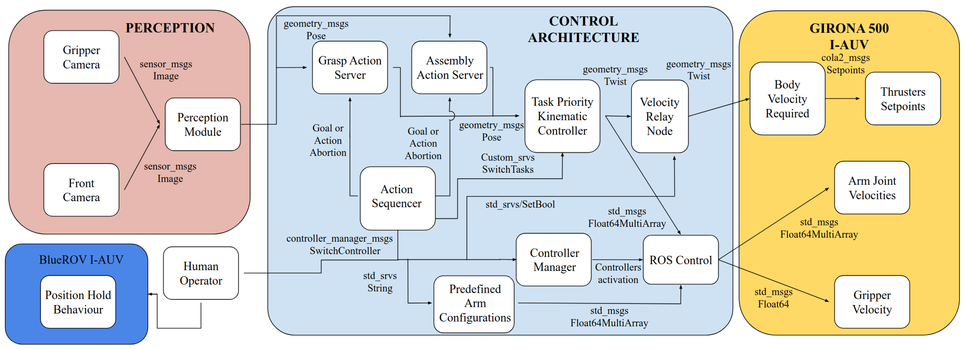
2.2. System Architecture

The overall system architecture is composed of two subsystems: the BlueROV, which operated in position-hold mode, and the Girona 500 I-AUV, whose architecture consists of three main modules. First, a multi-camera perception module estimates the poses of the objects. Second, a control architecture module manages the grasping and assembly actions, as well as the controllers and safety conditions that allow a safe intervention (without collisions). Finally, the I-AUV reads the body-frame velocities and interacts with the thrusters, while also reading the arm and gripper velocities to communicate with the manipulator communication interface. An overall system architecture diagram is shown in Figure 3. This figure provides a global overview of how the main modules and ROS nodes (perception, control, and hardware) interact through ROS interfaces. In the following paragraphs, each of the submodules within the control architecture is described in detail, reflecting the internal structure and behavior of the ROS nodes involved in the sequencing and execution of the manipulation task.
The control architecture module consists of three main parts, the action servers, the low-level controllers, and the high-level controllers, each of them are detailed next:
  • Action servers: These modules are ROS nodes that execute tasks, providing feedback and results. For example, the Grasp Action Server reads the object pose and sends an approach pose with an offset relative to the object. This node waits for the end-effector to reach the approach pose before sending a new grasp pose closer to the object. This cycle is repeated until the end-effector reaches the final grasp pose (i.e., its pose is within a defined threshold relative to the object pose). The action can also be automatically cancelled if the error between the end-effector and the object exceeds the pre-established threshold, or if the human operator decides to cancel the autonomous behavior for any reason. Additionally, the action node publishes a feedback message containing the current position and orientation error.
    In the case of the Assembly Action Server, the pose of the coupling part of the pipe and the left coupling part of the coupler were used to compute the misalignment error. A proportional controller was implemented to reduce this error and allow the system to successfully perform the assembly. The output of the controller was a feed-forward velocity command sent to the kinematic controller; this velocity represents the motion the end-effector must follow to bring the misalignment error to zero.
    To improve the robustness of the autonomous behavior, an additional mechanism was implemented. Specifically, if the coupler were already grasped, but the frontal camera could no longer detect it (typically because the manipulator arm obstructed the camera’s field of view), the system could still estimate the left-coupling part of the coupler pose. This was achieved by using the last known transformation between the end-effector and the left-coupling part of the coupler. By combining this transformation with the transform from the World NED frame to the end-effector frame, the system was able to compute an accurate estimate of the coupler’s global pose even without visual input.
  • Low-level controllers: This module includes the predefined arm configurations, the task-priority kinematic controller and the drivers required to send velocity commands to the I-AUV module. The predefined arm configurations node use the joint trajectory controller of the ROS control framework to move the arm to a predefined configuration. The task-priority controller used is based on the approach presented in [10], with small modifications to adapt it to the specific requirements of this application. These adaptations depend on the active action server: in the case of the grasping server, the input is a target pose, whereas in the assembly server, the input consists of linear and angular velocity commands. To handle both cases within a unified framework, two control tasks were implemented: one with a zero-valued proportional gain vector (used for feed-forward velocity input), and another with a unitary gain vector. Depending on the active action server, one of these tasks is enabled while the other is deactivated, allowing efficient switching between pose-based and velocity-based control. Additionally, a velocity relay node and a controller manager work alongside the ROS control node to manage the flow of velocity commands to the I-AUV. This architecture ensures that the human operator can interrupt the autonomous control at any time and switch to teleoperation if a potential collision is detected or if the safety of the system is compromised.
  • High-level controllers: These controllers function as a sequencer capable of triggering any action server by sending a goal or cancelling an ongoing action. Additionally, they can switch the active task in the task-priority algorithm or send a string-based request specifying a predefined arm configuration. These configurations include positions such as fold, unfold, look down, start assembly, or home position. In parallel to the sequencer, the human operator continuously monitors the intervention. If any failure occurs or the safety of the mission is compromised, the operator can intervene and take manual control of the system.

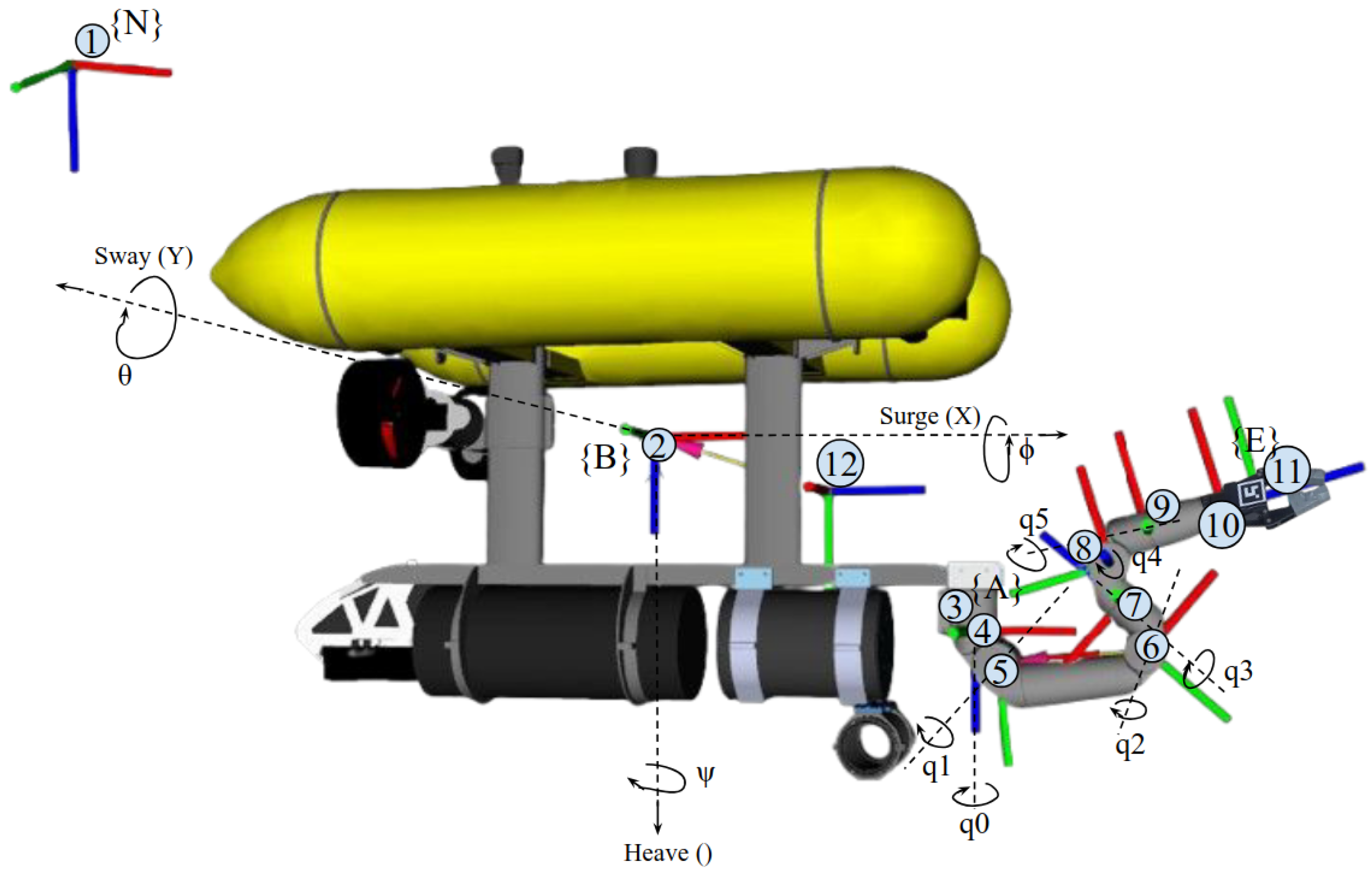
2.3. I-AUV Kinematics

The kinematics of the Girona 500 I-AUV are presented in this section. Since the BlueROV I-AUV remains in position-hold mode without actuating any joints of its arm, the kinematic analysis focuses only on the Girona 500 and assumes the pipe as a floating object.

2.3.1. Reference Frames

Figure 4 shows the frames and joints of the Girona 500 I-AUV and Table 1 explains the frame of the figure.

2.3.2. Definitions

First, the notation of the position and velocities of the robot are defined in the left of Table 2, the positions and velocities of the joints of the manipulator arm are shown on the right of Table 2.
From the mentioned notation, a pose vector from the robot and a configuration vector of the arm can be expressed as
η = η 1 T η 2 T T = x y z ϕ θ ψ T
q = q 0 q 1 q 2 q 3 q 4 q 5 q 6 T

2.3.3. Kinematic of Position

The pose of the base link of the AUV (Frame {B}) with respect to the North-East-Down (NED) (Frame {N}) can be expressed in a homogeneous matrix using the vector η of Equation (1). The homogeneous matrix is shown in Equation (3).
T B N ( η ) = R B N ( η 2 ) η 1 0 1 × 3 1
where the rotation matrix of Frame {B} with respect to Frame {N} is expressed as
R B N ( η 2 ) = R z ( ψ ) R y ( θ ) R x ( ϕ )
By expanding the elementary rotation matrices around the x, y, and z axes, the rotation matrix representing the orientation of Frame {B} with respect to Frame {N}, as a function of η 2 , is derived as
R z ( ψ ) = cos ψ sin ψ 0 sin ψ cos ψ 0 0 0 1 ; R y ( θ ) = cos θ 0 sin θ 0 1 0 sin θ 0 cos θ ; R x ( ϕ ) = 1 0 0 0 cos ϕ sin ϕ 0 sin ϕ cos ϕ
R B N ( η 2 ) = cos ψ cos θ sin ψ cos ϕ + cos ψ sin θ sin ϕ sin ψ sin ϕ + cos ψ sin θ cos ϕ sin ψ cos θ cos ψ cos ϕ + sin ψ sin θ sin ϕ cos ψ sin ϕ + sin ψ sin θ cos ϕ sin θ cos θ sin ϕ cos θ cos ϕ
The pose of the base of the manipulator arm (Frame {A}) with respect to the base link of the AUV (Frame {B}) can be expressed as
T A B = R 3 × 3 p 3 × 1 0 1 × 3 1
With R representing the rotation between frames. The position of the end-effector (Frame {E}) with respect to the base of the manipulator arm (Frame {A}) can be computed using the joint vector q and the Denavit–Hartenberg method for forward kinematics as follows:
T E A ( q ) = i = 1 n i 1 T i ( q i ) = R E A ( q ) t E A ( q ) 0 1 × 3 1
The matrices T i i 1 ( q i ) represent the transformations between consecutive links and are defined based on the Denavit–Hartenberg (DH) parameters. The specific DH parameters for the Bravo arm are provided in [35].
Finally, the transformation from the world NED (frame {N}) to the end-effector (frame {E}) can be computed using the transformations fromEquations (3), (7) and (8) as shown next:
T E N ( η , q ) = T B N ( η ) · T A B · T E A ( q )
Using this transformation, the end-effector pose with respect to the world can be represented as
η ee = η ee 1 η ee 2 T = x e e y e e z e e ϕ e e θ e e ψ e e T

2.3.4. Kinematic of Velocity

The quasi-velocities of the Underwater Vehicle Manipulation System (UVMS) are expressed as
ζ = ν T q ˙ T T = u v w p q r q ˙ 0 q ˙ 1 q ˙ 2 q ˙ 3 q ˙ 4 q ˙ 5 q ˙ 6 T
where ν represents both linear and angular velocities of the vehicle (frame {B}):
ν = ν 1 T ν 2 T T = u v w p q r T
The quasi-velocities of Equation (11) are related to the end-effector rate of change E e e using the Jacobian of the UVMS [36].
η ˙ ee = J ( q ) ζ
In which q represents the generalized coordinates of the UVMS.
q = η T q T T = x y z ϕ θ ψ q 0 q 1 q 2 q 3 q 4 q 5 q 6 T
In Equation (13) the complete Jacobian of the UVMS J ( q ) can be constructed using the Jacobian of the vehicle J v ( η ) , the Jacobian of the manipulator arm J m ( q ) and the linear velocity contribution due to the angular velocity of the vehicle through the cross-product (skew-symmetric) operator.
First, a transformation from the body velocity to the NED frame can be performed using the following expression:
η ˙ = J v ( η 2 ) ν
with η ˙ as the velocity in the NED frame {N}, transformed from the body velocity frame {B}. The presented Jacobian of the vehicle J v ( η 2 ) can be expressed as
J v ( η 2 ) = R B N ( η 2 ) 0 3 × 3 0 3 × 3 J ν 2 ( η 2 )
In which R B N ( η 2 ) was expressed in Equation (6) and J ν 2 ( η 2 ) is the angular transformation matrix from frame {B} to frame {N} and derived from
η 2 ˙ = J ν 2 ( η 2 ) ν 2
In which η 2 ˙ is the angular velocity vector in frame {N}, ν 2 is the angular velocity of the vehicle, and J ν 2 ( η 2 ) can be derived as
J ν 2 ( η 2 ) = 1 sin ϕ tan θ cos ϕ tan θ 0 cos ϕ sin ϕ 0 sin ϕ / cos θ cos ϕ / cos θ
As previously mentioned, the Jacobian of the manipulator J m ( q ) is required to compute the Jacobian of the UVMS J ( q ) and it can be represented as follows:
η ˙ En 1 A ν En 2 A = J m ( q ) q ˙
such that η ˙ En 1 A and ν En 2 A represent the lineal and angular velocity of the end-effector (frame {E}) with respect to the manipulator arm base (frame {A}). Also, and the manipulator Jacobian can be expressed as
J m ( q ) = J m , p ( q ) J m , o ( q )
This is given by the derivative of the position and orientation with respect to each joint of the manipulator:
J m , p ( q ) = η E n 1 q
J m , o ( q ) = ν E n 2 q
Finally, the complete UVMS Jacobian can be computed as follows:
η ˙ e e 1 ν e e 2 = J p ( q ) J o ( q ) ν q ˙ = J ( q ) ζ
where the position Jacobian is composed by the rotation from frame {B} with respect to frame {N}, the contribution of the vehicle’s angular motion to the linear velocity of the arm’s end-effector and the manipulator Jacobian.
J p ( q ) = R B N ( S R B N ( η 2 ) r BA B + S R A N η A,ee A ) R B N ( η 2 ) J m , p ( q )
In which S R B N ( η 2 ) r BA B is the displacement between the vehicle’s frame {B} and the base of the arm {A} and S R A N η Aee A represent the displacement between the base of the arm and the end-effector. These to terms are multiplied by the rotation of the vehicle with respect to the NED frame.
Finally, the orientation Jacobian can be computed as follows:
J o ( q ) = 0 3 × 3 R B N ( η 2 ) J m , o ( q )

2.3.5. Controllers

A proportional controller was applied to develop the assembly process. This type of controller was selected due to its simplicity and the low dynamic response requirements of the task, where both grasping and assembly motions are slow and do not involve rapid accelerations. Under such conditions, a proportional controller ensures sufficient stability and responsiveness without requiring more sophisticated control strategies, such as adaptive sliding mode control [37]. The control law is shown next:
u ( t ) = K p · e ( t )
In which K p is the proportional gain and the error is described as
e ( t ) = r ( t ) y ( t )
where the y ( t ) represents the pose of the grasped object with respect to the NED frame and r ( t ) represents the pose of the pipe also with respect to the NED frame.
The control of the orientation was implemented using quaternions. Given the current grasped object orientation q 1 and the target pipe orientation q 2 , both expressed as unit quaternions in the following form:
q 1 = x 1 y 1 z 1 w 1 , q 2 = x 2 y 2 z 2 w 2
The orientation error can be computed as a quaternion:
q err = q 2 q 1 1
where ⊗ denotes the quaternion product and q 1 1 is the inverse (or conjugate, since it is a unit quaternion):
q 1 1 = x 1 y 1 z 1 w 1
From the resulting error quaternion q err , we extract the rotation angle
θ = 2 · arccos ( q err , w )
and the rotation axis
u ^ = 1 sin ( θ / 2 ) q err , x q err , y q err , z , θ > ε 0 , otherwise
Finally, the angular error vector in axis-angle format is
ω error = θ · u ^
Using this form, the proportional controller can be applied to the orientation. The output of the control law of Equation (26) represents the feed-forward input of an end-effector configuration task from the task priority controller detailed in [10].

3. Experimental Setup

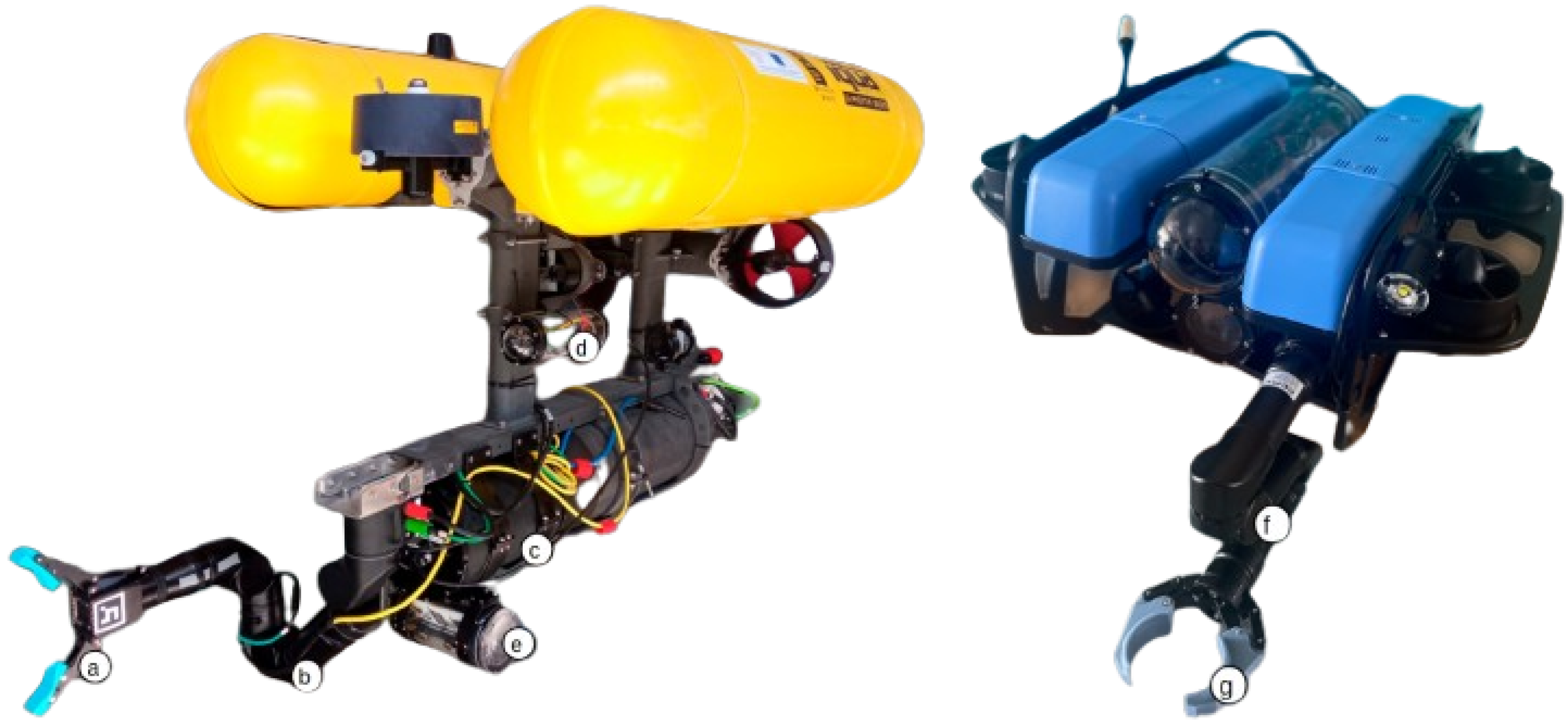
3.1. Mechatronic Integration

3.1.1. Girona 500 I-AUV

In this setup, the G500 I-AUV [38] was equipped with a Reach Bravo 7 manipulator [39]. The two-fingered end-effector designed by the CIRS laboratory in Girona, Spain, was installed in the manipulator. This end-effector includes a camera in the palm, allowing the robot to see at all times the object that is being grasped.
A watertight enclosure was installed in the AUV. This payload enclosure contains a Jetson Orin AGX, an Ethernet switch, and the necessary power adapters and connectors to provide the I-AUV with a wide range of input possibilities such as cameras, sensors, scanners, communication modems, etc. However, for this experiment, the only other gadget used in addition to the manipulator was a Low-Light HD USB camera connected to a Raspberry Pi 5 8GB enclosed in a watertight container. A picture of the G500 I-AUV and its payload can be seen on the left of Figure 5.
Regarding the communications, it is important to highlight that all image processing for ArUco marker detection is performed directly on the onboard computers (gripper and front), to which the camera is physically connected. This design minimizes the amount of data transmitted over the network, since only the detected ArUco poses are sent from the onboard computers to the main computer via Ethernet. Similarly, only velocity commands are issued from the control node to the manipulator. As a result, the total data exchanged within the control loop is very low. Given that all network links are wired (Gigabit Ethernet), and the onboard switch configuration involves at most three hops, communication latency is practically negligible and does not affect the performance of the control loop.

3.1.2. BlueROV I-AUV

For this experiment, the heavy configuration of the BlueROV2 [40] was used. This setup adds two thrusters to the standard configuration, which provides the vehicle with 6 doF. Moreover, the BlueROV2 was equipped with a Reach Alpha 5 manipulator [41]. An end-effector was designed and implemented to fit properly around the pipe. A picture of the experimental setup of the BlueROV2 can be seen on the right of Figure 5.

3.2. Grasp and Assembly Experiment

For this experiment, one pipe and one coupler were used. The first part consisted of a 3D-printed coupler with a cylindrical shape on the middle section and two blocks on each side of the cylinder. Each block had ArUco codes pasted onto each of the faces. The second element consisted of a 34 cm diameter PVC tube with two 3D-printed blocks with ArUco codes attached to each side of the tube. In this case, a shorter diameter was selected so that the Reach Alpha 5 manipulator could grasp the part. Both parts had neodymium magnets integrated in the blocks in order to aid the assembly operation. A detailed picture of the parts can be seen on the right of Figure 6.
The left part of the Figure 6 shows a recreation of the experimental setup where the BlueROV I-AUV was connected by a tether to the first Ground Control Station (GCS). This I-AUV is in position hold mode using the depth sensor [42] and a Doppler Velocity Log (DVL) A50 from Waterlinked [43]. The software running at the GCS was Qground Control [44], and the operator can control the robot using a Logitech F310 joystick [45]. For the assembly experiment, the BlueROV2 I-AUV was teleoperated using the joystick to send manual velocity commands until the robot reached the assembly position. At that point, an autonomous position-hold mode was activated via QGroundControl.
The Girona 500 I-AUV was also connected by a tether to a GCS, where Ubuntu 20.04 [46] and ROS Noetic [47] were running. Here, the operator was monitoring the intervention using the robot visualization tool Rviz [48]. Regarding synchronization of the system, both I-AUVs were synchronized via internet time servers using the Network Time Protocol (NTP), which ensured consistent ROS time across both platforms. Moreover, all control nodes relevant to the task execution (including the localization of the pipe and the coupler) were executed onboard the Girona 500 I-AUV. Finally, the complete experiment starts with the BlueROV I-AUV holding the pipe at a random position in the tank, far from the Girona 500 I-AUV. This robot starts floating near the surface and with the arm in the folded position, from there the operator triggered the sequencer, and the actions proceed as follows:
  • Unfold the arm.
  • Move the arm to the look down predefined position.
  • Trigger the grasp action server.
  • Move the arm to the start assembly predefined position.
  • The operator moves the BlueROV I-AUV close to the Girona 500 I-AUV.
  • Trigger the assembly action server and switch tasks to the end-effector configuration.
  • Switch task from end-effector configuration to AUV base configuration.
  • Send a pose to the AUV configuration to move away from the BlueROV I-AUV.

4. Results

This section is divided into the analysis of two different experiments: the first focuses on the grasping of the coupler, and the second on the assembly of the pipe with the coupler. The results include the position and orientation errors reported by the action server, the comparison between the target and real poses, and the output body and arm velocities generated by the controller. All of this data was analyzed throughout each experiment.
It is important to mention that the pose errors were calculated in the NED coordinate frame by comparing each axis component (X, Y, Z) of the end-effector pose with the corresponding components of the target pose. Orientation components were also evaluated in the same frame. Additionally, for the assembly task, a weighted moving average was applied to the target pose to reduce noise and ensure stability. The weighted average considered the current measurement (50%), the previous one (40%), and the one before that (30%).

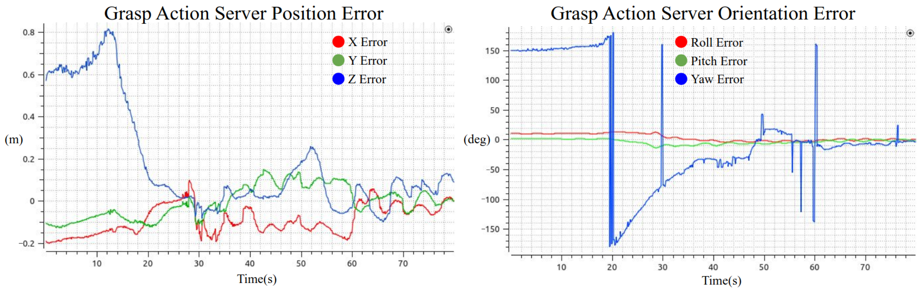
4.1. Coupler Grasping

In this experiment, the coupler was static at the bottom of the tank at approximately 4.8 m. Once the grasp action server was triggered, it sent a sequence of approach poses before the final grasp pose. The position and orientation errors shown in Figure 7 were computed between the end-effector and the actual output pose of the server (either an approach or grasp pose). This Figure also shows that the error in the Z-axis is initially large. When the action is triggered (at 12 s), this error begins to decrease until it reaches zero and remains near zero until approximately the second 50. This behavior corresponds to the first approach pose: once the robot’s end-effector reaches this position, it waits until the orientation is approximately aligned (±5 degrees), which occurs around the second 50. At that point, a new, closer approach pose is published. This explains why the error in Z increases again, and a similar behavior occurs around the second 60. This pattern results in the Z error having the appearance of a first-order multiple-step response. Finally, the position graph indicates that the grasp was successfully executed around the second 78. The orientation error shows how the roll and pitch error remain close to zero while the error in yaw has some noise, principally related to the ArUco orientation estimation.
Figure 8 shows the object pose versus the end-effector pose over time. It can be observed that the object’s pose was fluctuating, mainly due to noise in the visual pose estimation based on ArUco markers. Additionally, the navigation module of the Girona 500 contributed to this noise, as it just relies on a pressure sensor and a Doppler Velocity Log (DVL), which tends to drift over time and is particularly sensitive near the corners of the tank. This noise also affects the x and y axes. However, it is significantly reduced when the robot is close to the object, primarily because the ArUco markers appear larger in the image, making it easier for the algorithm to estimate the object’s position and orientation accurately.
Regarding orientation, the object’s roll and pitch were assumed to be zero, and the maximum deviation in the end-effector’s roll and pitch was 0.15 radians. The yaw of the object exhibited some abrupt variations at certain points, as previously mentioned. Nevertheless, as shown in the six plots, both the object pose and the end-effector pose converge to the same point shortly before the gripper is closed.
Figure 9 shows the velocities of the manipulator arm and the robot base. From the robot base velocity graph, it can be deduced that during the first 20 s, the controller moves the base in the linear Z direction, moving the robot closer to the object and also adjusting the linear X velocity. Once the robot reaches a grasping position, the velocities remain close to zero, except for some abrupt variations, which are also reflected in the arm’s velocity graph. Toward the end of the graph, it can be observed that the velocities of both the robot base and the manipulator arm converge to values near zero, indicating that the object and end-effector poses have aligned.
Figure 10 shows some images of the grasping process recorded from the on-hand camera, the Rviz visualization tool, and an external camera from another BlueROV that was teleoperated just for recording the experiment.

4.2. Pipe Assembly

In this experiment, the assembly action server pose error was computed from the difference in the World NED frame of both objects. Figure 11 shows that. It can be observed that the orientation error is fluctuating, this is mainly because of the poor image quality from the frontal camera. This camera is an HD low-light camera, but in scenarios where the light is abundant, the performance is not optimal. From the left image, the position error graph shows that the error in the three axes converges to zero.
Figure 12 shows both the pose of the pipe coupler and that of the coupler during the assembly. On the left side of the figure, the positions are shown. From the plots, it can be observed that the positions in all three axes converge. However, although the BlueROV I-AUV was operating in autonomous position hold mode, the Girona 500 I-AUV did not perceive the pipe coupler as stationary. This discrepancy is likely due to drift in the DVL sensor on the BlueROV I-AUV and poor ArUco marker detections from the Girona 500’s front camera. Nevertheless, detection improved significantly as the Girona 500 approached the pipe, which ensured that the critical part of the assembly was performed correctly. A similar trend can be observed in the orientation plots on the right side of the figure.
The velocities of the Girona 500 I-AUV are shown in Figure 13, where it can be observed that the base velocities remain very close to zero. This is mainly because the robot was positioned near the other robot holding the pipe. Similarly, the arm velocities were also low, primarily due to the low proportional gain, due to the high precision required to perform the assembly task.
Figure 14 shows a sequence of images from the assembly process at different moments. The left side of the figure displays the view from the frontal camera integrated into the Girona 500 I-AUV for this experiment, while the images on the right provide an external view captured by a second BlueROV, used just for recording purposes. The top pair of images represents the moment when the assembly action server was triggered. The middle pair captures the exact instant when the assembly was executed. Finally, the bottom pair shows the Girona 500 I-AUV opening the gripper and retreating from the BlueROV I-AUV, which is holding the assembled pipeline.

4.3. Action Server Error Metrics

The data presented in Table 3 correspond to the evaluation of pose error during both experiments: grasping and assembly. For the grasping task, the analysis was performed from second 50 to second 78 of the execution, which corresponds to the time window after the end-effector had reached the first approach pose and started moving gradually toward the final grasp target. For the assembly task, the entire 96-second duration of the action server’s activity was used, since the end-effector was already aligned with an approach pose at the beginning of the task.
The results show that both tasks achieved average Euclidean position errors under 10 cm. The grasping task had slightly lower orientation errors, but the yaw component showed high variability, possibly due to errors in ArUco detection or pose estimation. In contrast, the assembly task showed more consistent yaw values and overall lower standard deviations in orientation, indicating greater stability during execution.

5. Conclusions

The experimental results demonstrate the successful implementation of a cooperative manipulation framework using two I-AUVs, capable of accurately grasping and assembling pipeline segments in a controlled underwater environment. This contribution focuses on the successful demonstration that cooperative assembly between two I-AUVs is feasible, a milestone not previously achieved within our scientific community. In this preliminary experiment, magnets were embedded in the coupler parts to facilitate the assembly and validate the overall feasibility of underwater cooperative manipulation. It should be noted that the experiment was conducted in a controlled water tank environment with a depth of 5 m, unrestricted visibility, and no currents. Additionally, perception relied exclusively on visual input. While the primary objective of this work has been validated, demonstrating the feasibility of the proposed approach in a real-world context (i.e., the CIRTESU water tank), the system still requires further refinement and systematic testing in multiple trials to assess its robustness in less controlled environments.
An important detail to take into account is that the navigation sensors of both I-AUVs are not fully reliable, mainly due to drift in the DVL sensor over time and the noise of the perception module when the object is far from the camera. This can be improved by integrating a precise localization module, for example, using an ultra-short baseline (USBL) system or a simultaneous localization and mapping (SLAM) technique.
The proposed shared-autonomy architecture, where the operator remains in the loop and can take manual control of the system, represents an effective intermediate approach between fully autonomous and teleoperated control schemes. This approach helps bridge the gap in scenarios where large, world-class ROVs are operated in deep-sea environments by highly skilled ROV pilots, who carry significant responsibility due to the high value of the equipment. Enhancing operator comfort through shared-autonomy could reduce cognitive load and improve operational safety.
Finally, this overactuated system, composed of two I-AUVs with 10 degrees of freedom each, was constrained such that one vehicle, including its manipulator, maintained a fixed position in the World NED frame, while the other executed the assembly task. This methodology opens the door to a wide range of possibilities. For example, during the assembly process, the user could specify the desired location in the World NED frame where the assembly should occur, choose which robot performs the assembly, or even define the desired joint configuration to be followed during the task. Future developments and challenges, such as increasing the system’s autonomy, improving perception in poor visibility, and enabling wireless operations, are discussed in more detail in the next section.

6. Future Work

This work contributes to the state of the art in underwater manipulation by presenting a system architecture and mechatronic integration designed to address the problem of coordinate underwater pipeline assembly using two I-AUVs. Future work in this direction involves advancing the autonomy of the robots. Instead of relying on a predefined sequencer, the goal is to integrate an AI-based agent capable of making real-time decisions based on varying scenarios while ensuring the robot’s safety. Another promising research line is the development of an underwater wireless communication module, which would enable wireless intervention missions. This module will be based on Visual Light Communications (VLC), where the bandwidth is still restricted to about 10 Mbps.
Additionally, while the use of ArUco markers has proven effective for object pose estimation, it raises the question: what happens in scenarios where markers cannot be attached to the objects, where unknown objects are present, or where visibility is poor? In such cases, developing a robust visual–acoustic perception system becomes essential. Acoustic sensors, such as multibeam sonars, can be employed to detect and map objects, and their integration with monocular or stereo vision can significantly enhance the perception capabilities required for underwater robotic interventions. Among these sensors, multibeam imaging sonars are particularly promising for manipulation tasks, as they provide acoustic imagery with a wide field of view. However, fusing acoustic and visual data presents specific challenges. For example, scanning imaging sonars, while offering detailed acoustic images, typically rely on a mechanically rotating motor to sweep the environment, which introduces significant latency and complicates temporal alignment with visual sensor data. Nonetheless, recent advances in sonar technology are leading to the emergence of 3D multibeam imaging sonars capable of generating point clouds at increasingly higher frame rates. These improvements are making it more feasible to integrate acoustic and visual modalities for real-time underwater perception and manipulation. Finally, alignment is a critical aspect when fusing data from different perception sources, and dedicated calibration methods must be developed to address this challenge.

Author Contributions

Conceptualization, S.L.-B., P.J.S., R.M.-P. and A.S.; methodology, S.L.-B., P.J.S. and R.M.-P.; software, S.L.-B.; validation, S.L.-B. and A.S.; formal analysis, S.L.-B., P.J.S., R.M.-P. and A.S.; investigation, S.L.-B., P.J.S. and R.M.-P.; resources, S.L.-B., P.J.S., R.M.-P. and A.S.; data curation, S.L.-B.; writing—original draft preparation, S.L.-B. and A.S.; writing—review and editing, S.L.-B., P.J.S., R.M.-P. and A.S.; visualization, S.L.-B., P.J.S., R.M.-P. and A.S.; supervision, S.L.-B., P.J.S., R.M.-P. and A.S.; project administration, S.L.-B., P.J.S. and R.M.-P.; funding acquisition, P.J.S. and R.M.-P. All authors have read and agreed to the published version of the manuscript.

Funding

This paper is part of the R&D&i project PID2020-115332RB-C31 funded by MCIN/AEI/ 10.13039/501100011033.

Institutional Review Board Statement

Not applicable.

Informed Consent Statement

Not applicable.

Data Availability Statement

Video of the experiment is available at https://www.youtube.com/watch?v=x2kAGlUGze4 accessed on 25 July 2025.

Acknowledgments

The authors thank the UdG team at the CIRS laboratory for their collaboration in the gripper design and for hosting the first author during a research stay, as well as for the knowledge shared and the software support that resulted from it. The authors thank Andrea Pino for his invaluable support in mechanical design and manufacturing of the Girona 500 I-AUV payload.

Conflicts of Interest

The authors declare no conflicts of interest.

Abbreviations

The following abbreviations are used in this manuscript:
AUVAutonomous Underwater Vehicle
CIRTESUCenter for Robotics and Underwater Technologies Research
DVLDoppler Velocity Log
GCSGround Control Station
HRIHuman–Robot Interface
I-AUVAutonomous Underwater Vehicle for Intervention
UAVUnmanned Aerial Vehicles
UGVUnmanned Ground Vehicles
LARSLaunching and Recovering System
NEDNorth East Down
ROVRemote Operated Vehicle
SLAMSimultaneous Localization and Mapping
USBLUltra Short Baseline
UVMSUnderwater Vehicles Manipulator Systems
VLCVisual Light Communications

References

  1. Yoon, S.; Qiao, C. Cooperative search and survey using autonomous underwater vehicles (AUVs). IEEE Trans. Parallel Distrib. Syst. 2010, 22, 364–379. [Google Scholar] [CrossRef]
  2. Petillot, Y.R.; Antonelli, G.; Casalino, G.; Ferreira, F. Underwater robots: From remotely operated vehicles to intervention-autonomous underwater vehicles. IEEE Robot. Autom. Mag. 2019, 26, 94–101. [Google Scholar] [CrossRef]
  3. Evans, J.; Redmond, P.; Plakas, C.; Hamilton, K.; Lane, D. Autonomous docking for Intervention-AUVs using sonar and video-based real-time 3D pose estimation [Conference presentation]. In Proceedings of the Oceans 2003 MTS/IEEE Conference, San Diego, CA, USA, 22–26 September 2003. [Google Scholar]
  4. Marani, G.; Choi, S.K.; Yuh, J. Underwater autonomous manipulation for intervention missions AUVs. Ocean Eng. 2009, 36, 15–23. [Google Scholar] [CrossRef]
  5. Prats, M.; Pomerleau, F.; Palomeras, N.; Ribas, D.; Garcia, R.; Sanz, P.J. Multipurpose autonomous underwater intervention: A systems integration perspective [Conference presentation]. In Proceedings of the 20th Mediterranean Conference on Control and Automation (MED), Barcelona, Spain, 3–6 July 2012. [Google Scholar] [CrossRef]
  6. Prats, M.; Ribas, D.; Palomeras, N.; Garcia, R.; Carreras, M.; Sanz, P.J. Reconfigurable AUV for intervention missions: A case study on underwater object recovery. Intell. Serv. Robot. 2012, 5, 19–31. [Google Scholar] [CrossRef]
  7. Carrera, A.; Palomeras, N.; Hurtós, N.; Kormushev, P.; Carreras, M. Cognitive system for autonomous underwater intervention. Pattern Recognit. Lett. 2015, 67, 91–99. [Google Scholar] [CrossRef]
  8. Palomeras, N.; Peñalver, A.; Massot-Campos, M.; Negre, P.L.; Fernández, J.J.; Ridao, P.; Sanz, P.J.; Oliver-Codina, G. I-AUV docking and panel intervention at sea. Sensors 2016, 16, 1673. [Google Scholar] [CrossRef]
  9. López-Barajas, S.; Sanz, P.J.; Marín-Prades, R.; Echagüe, J.; Realpe, S. Network congestion control algorithm for image transmission—HRI and visual light communications of an autonomous underwater vehicle for intervention. Future Internet 2025, 17, 10. [Google Scholar] [CrossRef]
  10. Pi, R.; Palomeras, N.; Carreras, M.; Sanz, P.J.; Oliver-Codina, G.; Ridao, P. OPTIHROV: Optically linked hybrid autonomous/remotely operated vehicle, beyond teleoperation in a new generation of underwater intervention vehicles. In Proceedings of the OCEANS 2023-Limerick, Limerick, Ireland, 5–8 June 2023. [Google Scholar]
  11. Burgard, W.; Moors, M.; Fox, D.; Simmons, R.; Thrun, S. Collaborative multi-robot exploration [Conference paper]. In Proceedings of the 2000 IEEE International Conference on Robotics and Automation (ICRA), San Francisco, CA, USA, 24–28 April 2000. [Google Scholar]
  12. Reid, R.; Cann, A.; Meiklejohn, C.; Poli, L.; Boeing, A.; Braunl, T. Cooperative multi-robot navigation, exploration, mapping and object detection with ROS [Conference paper]. In Proceedings of the 2013 IEEE Intelligent Vehicles Symposium (IV), Gold Coast, QLD, Australia, 23–26 June 2013. [Google Scholar]
  13. Hayajneh, M.; Al Mahasneh, A. Guidance, Navigation and Control System for Multi-Robot Network in Monitoring and Inspection Operations. Drones 2022, 6, 332. [Google Scholar] [CrossRef]
  14. Hinostroza, M.A.; Lekkas, A.M.; Transeth, A.; Luteberget, B.; de Jonge, C.; Sagatun, S.I. Autonomous Inspection and Maintenance Operations employing Multi-Robots [Conference paper]. In Proceedings of the 20th IEEE/ASME International Conference on Mechatronic and Embedded Systems and Applications (MESA), Genova, Italy, 2–4 September 2024. [Google Scholar]
  15. Feng, Z.; Hu, G.; Sun, Y.; Soon, J. An overview of collaborative robotic manipulation in multi-robot systems. Annu. Rev. Control 2020, 49, 113–127. [Google Scholar] [CrossRef]
  16. Jimenez-Cano, A.E.; Martin, J.; Heredia, G.; Ollero, A.; Cano, R. Control of an aerial robot with multi-link arm for assembly tasks [Conference paper]. In Proceedings of the 2013 IEEE International Conference on Robotics and Automation (ICRA), Karlsruhe, Germany, 6–10 May 2013; pp. 4916–4921. [Google Scholar] [CrossRef]
  17. Du, Z.; Li, W.; Shi, G. Multi-USV collaborative obstacle avoidance based on improved velocity obstacle method. ASCE-ASME J. Risk Uncertain. Eng. Syst. Part A Civ. Eng. 2024, 10, 04023049. [Google Scholar] [CrossRef]
  18. Zhang, J.; Ren, J.; Cui, Y.; Fu, D.; Cong, J. Multi-USV task planning method based on improved deep reinforcement learning. IEEE Internet Things J. 2024, 11, 18549–18567. [Google Scholar] [CrossRef]
  19. Novák, F.; Báča, T.; Saska, M. Collaborative Object Manipulation on the Water Surface by a UAV-USV Team Using Tethers [Conference paper]. In Proceedings of the 2024 IEEE/RSJ International Conference on Intelligent Robots and Systems (IROS), Abu Dhabi, United Arab Emirates, 14–18 October 2024. [Google Scholar]
  20. López-Barajas, S.; Sanz, P.J.; Marín-Prades, R.; Gómez-Espinosa, A.; González-García, J.; Echagüe, J. Inspection operations and hole detection in fish net cages through a hybrid underwater intervention system using deep learning techniques. J. Mar. Sci. Eng. 2024, 12, 80. [Google Scholar] [CrossRef]
  21. Sarda, E.I.; Dhanak, M.R. A USV-Based Automated Launch and Recovery System for AUVs. IEEE J. Ocean. Eng. 2017, 42, 37–55. [Google Scholar] [CrossRef]
  22. González-García, J.; Gómez-Espinosa, A.; Cuan-Urquizo, E.; García-Valdovinos, L.G.; Salgado-Jiménez, T.; Cabello, J.A.E. Autonomous Underwater Vehicles: Localization, navigation, and communication for collaborative missions. Appl. Sci. 2020, 10, 1256. [Google Scholar] [CrossRef]
  23. Casalino, G.; Caccia, M.; Caselli, S.; Melchiorri, C.; Antonelli, G.; Caiti, A.; Indiveri, G.; Cannata, G.; Simetti, E.; Torelli, S.; et al. Underwater intervention robotics: An outline of the Italian national project MARIS. Mar. Technol. Soc. J. 2016, 50, 98–107. [Google Scholar] [CrossRef]
  24. IRS Lab. TWINBOT Project (2018–2021). 2021. Available online: https://blogs.uji.es/irs/projects/twinbot-2018-2021/ (accessed on 6 June 2025).
  25. Simetti, E.; Casalino, G. Manipulation and transportation with cooperative underwater vehicle-manipulator systems. IEEE J. Ocean. Eng. 2017, 42, 782–799. [Google Scholar] [CrossRef]
  26. Heshmati-alamdari, S.; Karras, G.C.; Kyriakopoulos, K.J. A distributed predictive control approach for cooperative manipulation of multiple underwater vehicle manipulator systems [Conference paper]. In Proceedings of the 2019 International Conference on Robotics and Automation (ICRA), Montreal, QC, Canada, 20–24 May 2019. [Google Scholar]
  27. Conti, R.; Meli, E.; Ridolfi, A.; Allotta, B. An innovative decentralized strategy for I-AUVs cooperative manipulation tasks. Robot. Auton. Syst. 2015, 72, 261–276. [Google Scholar] [CrossRef]
  28. Heshmati-Alamdari, S.; Karras, G.C.; Kyriakopoulos, K.J. A predictive control approach for cooperative transportation by multiple underwater vehicle manipulator systems. IEEE Trans. Control Syst. Technol. 2022, 30, 917–930. [Google Scholar] [CrossRef]
  29. Pi, R.; Cieślak, P.; Ridao, P.; Sanz, P.J. TWINBOT: Autonomous underwater cooperative transportation. IEEE Access 2021, 9, 37668–37684. [Google Scholar] [CrossRef]
  30. Ultralytics. YOLOv8 Models Documentation. 2025. Available online: https://docs.ultralytics.com/es/models/yolov8/#performance-metrics (accessed on 22 June 2025).
  31. Sanz, P.J.; Requena, A.; Inesta, J.M.; Del Pobil, A.P. Grasping the not-so-obvious: Vision-based object handling for industrial applications. IEEE Robot. Autom. Mag. 2005, 12, 44–52. [Google Scholar] [CrossRef]
  32. Veiga Almagro, C.; Lunghi, G.; Di Castro, M.; Centelles Beltran, D.; Marín Prades, R.; Masi, A.; Sanz, P.J. Cooperative and multimodal capabilities enhancement in the CERNTAURO human–robot interface for hazardous and underwater scenarios. Appl. Sci. 2020, 10, 6144. [Google Scholar] [CrossRef]
  33. Open Source Computer Vision. 2022. Available online: https://docs.opencv.org/4.x/d5/dae/tutorial_aruco_detection.html (accessed on 3 June 2025).
  34. Fictionlab. Opencv ArUco. 2022. Available online: https://github.com/fictionlab/ros_aruco_opencv.git (accessed on 3 June 2025).
  35. Reach Robotics. Inverse Kinematics and Cartesian Control. 2022. Available online: https://reachrobotics.com/blog/inverse-kinematics-and-cartesian-control/ (accessed on 16 June 2025).
  36. Antonelli, G. Underwater Robots (Springer Tracts in Advanced Robotics); Springer: Cham, Switzerland, 2013; Volume 96. [Google Scholar]
  37. Lopez-Barajas, S.; Sanz, P.J.; Marin, R.; Solis, A.; Echagüe, J.; Castañeda, H. Seguimiento de trayectoria de un AUV para la inspección de jaulas de red utilizando control por modos deslizantes. Jorn. Automática 2024, 45. [Google Scholar] [CrossRef]
  38. IQUA Robotics. Girona 500 AUV. 2025. Available online: https://iquarobotics.com/girona-500-auv (accessed on 10 June 2025).
  39. Reach Robotics. Reach Bravo 7—7-Function Robotic Manipulator. 2025. Available online: https://quote.reachrobotics.com/product/bravo-manipulators/bravo-7/ (accessed on 10 June 2025).
  40. Blue Robotics. BlueROV2 Heavy Configuration Retrofit Kit. 2025. Available online: https://bluerobotics.com/store/rov/bluerov2-upgrade-kits/brov2-heavy-retrofit/ (accessed on 10 June 2025).
  41. Reach Robotics. Reach Alpha—5-Function Robotic Manipulator. 2025. Available online: https://reachrobotics.com/products/manipulators/reach-alpha/ (accessed on 10 June 2025).
  42. Blue Robotics. Bar30 High-Resolution Depth/Pressure Sensor. 2025. Available online: https://bluerobotics.com/store/sensors-cameras/sensors/bar30-sensor-r1/ (accessed on 10 June 2025).
  43. Water Linked. DVL A50 Doppler Velocity Log. 2025. Available online: https://waterlinked.com/shop/dvl-a50-1248?attr=234,236,238 (accessed on 10 June 2025).
  44. QGroundControl. QGroundControl—Ground Control Station. 2025. Available online: https://qgroundcontrol.com/ (accessed on 10 June 2025).
  45. Logitech. F310 Gamepad. 2025. Available online: https://www.logitechg.com/es-es/products/gamepads/f310-gamepad.html (accessed on 10 June 2025).
  46. Ubuntu. Ubuntu 20.04 LTS (Focal Fossa)—Release Downloads. 2025. Available online: https://releases.ubuntu.com/focal/ (accessed on 10 June 2025).
  47. ROS. ROS Noetic Ninjemys. 2025. Available online: https://wiki.ros.org/noetic (accessed on 10 June 2025).
  48. ROS. RViz-ROS Visualization Tool. 2025. Available online: https://wiki.ros.org/rviz (accessed on 10 June 2025).
Figure 1. Segmentation results. From left to right: manual segmentation; segmentation and computed grasping points for the pipe; segmentation and grasping points for the coupler before grasping; and segmentation with the coupler at the grasping point. The arrows in the images represent the center of the object and the center of the gripper camera.
Jmse 13 01490 g001
Figure 2. Diagram of the perception module. The standard ROS messages used are represented with the arrows.
Jmse 13 01490 g002
Figure 3. Diagram of the system architecture. Four modules are presented in this diagram: perception, BlueROV I-AUV, Girona500 I-AUV, and control architecture. The standard ROS messages and services link the different modules and submodules and are represented with arrows.
Jmse 13 01490 g003
Figure 4. Girona 500 I-AUV kinematic system.
Jmse 13 01490 g004
Figure 5. On the left the G500 I-AUV. (a) Two-fingered end-effector with camera, (b) Reach Bravo 7 manipulator, (c) Payload enclosure, (d) Low-Light HD USB camera enclosure, (e) Jetson Orin and stereo camera enclosure. On the right, the BlueROV I-AUV. (f) Reach Alpha 5 manipulator, (g) Custom end-effector for pipe grasping.
Jmse 13 01490 g005
Figure 6. On the left, a diagram representing the experimental setup. On the right, the objects: (a) 3D-printed coupler, (b) PVC pipe, (c) 3D-printed blocks with ArUco codes and neodimium magnets.
Jmse 13 01490 g006
Figure 7. Grasp action server error over time. Position (left) and orientation (right) errors measured in the NED frame between the end-effector and the grasp server’s actual output.
Jmse 13 01490 g007
Figure 8. Object and end-effector pose over time. On the left, the positions, and on the right, the orientation, both with respect to the NED frame.
Jmse 13 01490 g008
Figure 9. Arm and robot base velocities over time during the grasping action. At the top, the joint velocities of the arm, and at the bottom, the robot’s base linear and angular velocities.
Jmse 13 01490 g009
Figure 10. At the top left, the RViz interface displays the robot description. Below, on the lower left, an image from the gripper camera captures the scene just before the grasp. In the center left, another view from the gripper camera shows the object immediately after the grasp. On the right, an external view shows the Girona 500 I-AUV executing the grasp operation.
Jmse 13 01490 g010
Figure 11. Assembly action server error over time. Position error on the left and orientation error on the right. The error is computed in the NED frame and represents the difference between the pipe connectors.
Jmse 13 01490 g011
Figure 12. Pipe coupler and coupler pose over time, both expressed in the NED frame. The plots show the evolution of the assembly process, which concludes when both poses converge, indicating successful completion of the task.
Jmse 13 01490 g012
Figure 13. Arm and robot base velocities over time during the assembly action. At the top, the joint velocities of the arm, and at the bottom, the robot’s base linear and angular velocities.
Jmse 13 01490 g013
Figure 14. Assembly process. On the left, the frontal camera of the Girona 500 I-AUV, and on the right, an external view of the experiment.
Jmse 13 01490 g014
Table 1. Reference frames used in the AUV-manipulator system.
#Frame NameDescription
1NEDNorth-East-Down reference frame
2AUV_base_linkMain body frame of the AUV
3Arm_base_linkBase frame of the manipulator mounted on the AUV
4Arm_joint_0Frame at joint 0 of the manipulator (base rotation)
5Arm_joint_1Frame at joint 1 (shoulder pitch)
6Arm_joint_2Frame at joint 2 (elbow pitch)
7Arm_joint_3Frame at joint 3 (elbow roll)
8Arm_joint_4Frame at joint 4 (wrist pitch)
9Arm_joint_5Frame at joint 5 (wrist roll)
10Arm_joint_6Frame at joint 6 (push rod)
11End_effector_cameraCamera mounted at the end effector
12Front_cameraFront-facing camera on the AUV
Table 2. Degrees of freedom, positions, and velocities of the I-AUV.
VehicleArm
Name DoF Pos. Vel. Name DoF Pos. Vel.
SurgeX trans.xuJoint 0Revolute q 0 q ˙ 0
SwayY trans.yvJoint 1Revolute q 1 q ˙ 1
HeaveZ trans.zwJoint 2Revolute q 2 q ˙ 2
RollX rot. ϕ pJoint 3Revolute q 3 q ˙ 3
PitchY rot. θ qJoint 4Revolute q 4 q ˙ 4
YawZ rot. ψ rJoint 5Revolute q 5 q ˙ 5
Joint 6Prismatic q 6 q ˙ 6
Table 3. Comparison of pose error statistics between the grasping and assembly action servers. Position errors (X, Y, Z, and Euclidean) are expressed in meters (m), and orientation errors (roll, pitch, yaw) are expressed in degrees (deg).
ComponentGrasping TaskAssembly Task
MeanStd DevRMSEMeanStd DevRMSE
X (m)−0.06630.06330.0917−0.03230.05580.0645
Y (m)0.03050.05050.0590−0.01230.06030.0616
Z (m)0.04640.09120.10230.04270.12850.1354
Euclidean error (m)0.13240.06950.14950.14180.07850.1621
ROLL (deg)−1.08931.53141.87932.412414.856415.0579
PITCH (deg)−3.04962.33483.8407−0.34956.72876.7390
YAW (deg)−3.114325.732825.9206−9.41327.158311.8251
Disclaimer/Publisher’s Note: The statements, opinions and data contained in all publications are solely those of the individual author(s) and contributor(s) and not of MDPI and/or the editor(s). MDPI and/or the editor(s) disclaim responsibility for any injury to people or property resulting from any ideas, methods, instructions or products referred to in the content.

