Abstract
To meet the growing demand for space launches and overcome the limitations of land-based launches, the scientific research community is committed to developing safer and more flexible offshore rocket launch technologies. Their core carriers—marine platforms—are directly exposed to the dynamic and variable marine environment. The complex coupling effects of wind, waves, and currents impose severe challenges upon these platforms, causing complex phenomena such as severe rocking. These phenomena pose severe threats to and significantly interfere with the stability and normal execution of offshore rocket launch operations. This study employs CFD simulation software to analyze liquid sloshing within a cylindrical tank, both with and without baffles. Following validation of the natural frequency, the analysis focuses on the suppression effect of different baffle positions and configurations on tank sloshing. The numerical simulation results indicate the following: Incorporating baffles alters the natural frequency of liquid sloshing within the tank and effectively suppresses the free surface motion. The suppression of the wave surface motion improves as the baffle is positioned closer to the free surface and as the number of perforations in the baffle increases. However, when the number of perforations exceeds a certain threshold, further increasing it yields negligible improvement in the suppression of the sloshing wave surface motion.
1. Introduction
It is widely recognized that marine environmental conditions evolve rapidly, imposing stringent demands on offshore platforms as critical infrastructure. Particularly under harsh metocean conditions, platforms experience complex dynamic loads from wind, waves, and currents—both during stationary positioning and operational phases. Consequently, comprehensive investigation of seaborne satellite launch platforms operating in such challenging ocean environments is imperative.
In recent years, many scholars at home and abroad have studied the fluid characteristics of the phenomenon of liquid shaking in a liquid tank. The phenomenon of sloshing is very relevant for vessels that transport liquid petroleum products—crude/chemical oil tankers—as well as for vessels that transport liquefied petroleum or natural gas—LPG/LNG tankers. Liquid sloshing in the tank not only weakens the stability of the ship and various liquid storage tanks, but also threatens the ship’s structural integrity and the safety of its personnel due to the shock loads it induces [1,2,3,4]. Because of this, scholars at home and abroad have carried out systematic research on the hydrodynamic characteristics of liquid tank sloshing.
McCarty and Stephens [5] performed numerical simulations of the sloshing of a spherical tank partially filled with liquid, and showed that the higher the free liquid level inside the sphere, the higher the natural frequency of liquid sloshing; and the larger the radius of the tank, the lower the natural frequency of liquid. Francecutto et al. [6] conducted a numerical calculation study on a liquid tank with damping plates in 1996 based on the RANS equation, and the results showed that a liquid tank with damping plates also had a good anti-roll effect. Ahmed F. Abdel Gawad et al. [7] used numerical calculations to change the parameters of a U-shaped liquid tank, and discussed its anti-roll effect in detail, and concluded that the liquid tank should be equipped with a damping structure to control the fluid movement, and a well-designed and tuned liquid tank can be very effective in reducing roll. Abbas Maleki et al. [8] conducted a liquid sloshing study on cylindrical liquid tanks with baffles in 2008 and showed that annular baffles were more effective in reducing sloshing oscillations. Jedediah Morse Store et al. [9] performed an experimental, numerical analysis of water and liquid nitrogen in the liquid tank of a spherical storage tank. Jun Liu et al. [10] analyzed the sloshing performance of various barrel-shaped cylindrical liquid tanks based on the isometric boundary element method, and the results showed that arranging three circular baffles along the excitation direction was the best arrangement to suppress the sloshing of liquids.
Owing to its inherent advantages in handling free surfaces, the meshless particle method has been widely adopted for simulating violent free-surface flows [11,12,13,14]. Leng Fei [15] studied the effect of a damping plate on liquid sloshing in a liquid tank based on the SPH method, and the results showed that the presence of a damping plate could make the liquid sloshing return to calm faster. Liu Fu [16] carried out a numerical simulation of liquid sloshing with or without damping plates in a prismatic liquid tank based on the SPH method, and the results showed that the addition of damping plates could reduce the pressure at the top of the liquid tank and make the liquid sloshing amplitude lower. Wu Jianlin et al. [17] discussed the influence of a U-shaped liquid tank structure’s damping on the roll reduction performance based on the CFD method, and proposed a method based on numerical calculations to evaluate the roll reduction effect of the tank in regular waves. In the same year, Luo Hanbing [18], based on the open-source software OpenFOAM and a calculation package based on the two-phase flow solver InterFOAM, numerically predicted the inherent period and damping of liquid sloshing in a liquid tank model, and the results showed that a damping plate in the liquid tank would increase the period and damping, and the liquid-level height in the liquid tank would increase significantly.
Mi-An Xue et al. [19] studied viscous liquid sloshing in liquid tanks with internal baffles of different shapes and arrangements based on the three-dimensional (3-D) numerical model NEWTANK, and the results showed that the height of the free liquid level near the liquid bulkhead decreased due to the presence of an annular baffle, and when the annular baffle was close to the free liquid level and the width increased, the annular baffle was more effective in reducing violent liquid sloshing and the presence of the annular baffle caused the peak response frequency to shift to the lower side. Dasgupta A (2011) [20] analyzed the effects of the tank cross-section and longitudinal baffle on transient liquid sloshing of partially filled road tankers based on CFD methods, and the results showed that the addition of longitudinal baffles can significantly reduce the motion of the roll plane. Budiansky (2012) [21] performed numerical simulations of tank sloshing in empty, semi-liquid-filled, and fully liquid-filled spherical tanks, and showed that the natural frequency of liquid sloshing mainly depends on the tank radius and a dimensionless parameter determined in the project. Nema P (2014) [22], based on the finite volume method (FVM)-based fluid volume method (VOF), studied the shaking behavior of a three-dimensional rectangular liquid tank with and without a baffle under external force excitation, showing that the sloshing would become violent under the excitation of the natural frequency under resonance conditions, showing over-turning and causing a serious impact on the roof wall of the tank. A baffle was set in the tank, which acted as a damper and minimized the number of sloshing waves. At the same time, the higher the level of the tank, the greater the complexity of the liquid shaking. Rohit Suyal (2016) [23] conducted a CFD analysis of fuel sloshing inside a cylindrical tank with and without damping baffles at linear acceleration, and the study showed that baffles with more holes on the surface were more effective in reducing longitudinal forces, but baffles with a single central cavity could reduce vertical forces, and for controlling moments, single-cavity baffles proved to be more effective. Yg A et al. [24] conducted a numerical study on the influence of baffles on liquid sloshing in three-dimensional rectangular liquid tanks based on the nonlinear boundary element method, and the results showed that the shape of the baffle plays a non-negligible role in the sloshing of liquid tanks.
Liang Lihua (2021) et al. [25] analyzed the influence of a T-baffle arrangement on the intrinsic period of the tank through computational fluid dynamics software, and the results showed that changing the number of T-baffles can increase the intrinsic period of the tank to a certain extent. Zhao Minghan (2022) [26] used the VOF method to numerically simulate liquid sloshing in a trapezoidal liquid tank in a vehicle, and added different longitudinal baffles in the liquid tank, and the results showed that the more damping baffles, the faster the stabilization of the liquid sloshing free liquid level, and the lower the bulkhead pressure. Dongxi Liu et al. [27] conducted a series of model experiments in a fully filled cylindrical tank containing two immiscible liquids. It was found that the separation surface rotary sloshing in a two-layer liquid system was much more intricate than one-layer liquid rotary sloshing due to the generation of multitudinous short waves in the long wave. In Changle Zhang et al. [28], based on an improved moving-particle semi-implicit method, the BM-MPS method, the damping effect of a vertical slotted screen under rotation excitation was simulated and studied, and the influence of baffle porosity and the rotation amplitude on the resonance period and impact pressure was discussed. The results showed that the porosity had an obvious effect on the resonance period. Qiong Zhang et al. [29] studied the sloshing characteristics of a liquid cargo compartment under combined rollover and surge excitation conditions. Sarat Chandra Mohapatra et al. [30] analyzed wave-induced forces and moments acting on a cylinder, along with the circumferential pressure distribution around a vertical cylindrical structure, using CFD simulations.
To sum up, in traditional marine engineering, the addition of baffles has been widely confirmed as an effective means of sloshing suppression. Based on this mature method, this study analyzes the problem of liquid tank sloshing in maritime satellite launch platforms.
This study focuses on the specific application scenario of offshore satellite launch platforms, where propellant storage tanks (usually storing liquid oxygen, kerosene, etc.) are fundamentally different from traditional ship ballast tanks or FPSO oil storage tanks. The propellant storage tanks used to serve the rocket launch process are extremely stable—structural resonances or propellant cavitation caused by sloshing loads can lead to catastrophic consequences (e.g., explosions). At the same time, the Sea Launch platform is extremely sensitive to space and weight. While sloshing is often suppressed by adding baffles in traditional offshore engineering, the applicability of large-sized baffles in a launch platform environment can take up valuable propellant space and potentially interfere with the filling/discharge process. With the rapid advancement of computer technology, numerical simulation has become one of the most important tools in the study of liquid sloshing. Therefore, this paper uses STAR-CCM+2020 version to take the cylindrical storage tank of the hypothetical offshore rocket satellite launch platform as the research object, compares and verifies the cylindrical model (the model is idealized), and then analyzes the inhibition effect of the damping plate on the sloshing in the cylinder liquid tank, and then analyzes the influence of different positions of the damping plate and different types of damping plates on the amplitude of the liquid tank sloshing and the bulkhead pressure, and studies their inhibition effects.
2. Numerical Analysis Methods and Theory
2.1. Governing Equations
The turbulence model selected in this study incorporates the continuity equation, energy equation, and momentum equation that satisfy Newton’s second law. The continuity equation, based on the principle of mass conservation, is expressed as (1): the increase in mass within a control volume per unit time equals the net mass inflow into the volume during the same time interval.
In the equation, V(t) represents the volume of the fluid element; m denotes the mass of the fluid within the control volume; and ρ stands for the fluid density (in this study, it is assumed that the fluid density remains constant during the modeling process).
According to the mass transfer Equation (2), Equation (3) can be derived.
Based on the mass transfer Equation (2), defining (mass density) leads to Equation (3).
The continuity equation can be derived from the arbitrariness of the fluid element volume V(t), as shown in (4):
As shown in Equation (5), the rate of change of fluid momentum with respect to time within a fluid element is equal to the force acting on the fluid element.
In the equation, S represents the boundary condition; denotes the body force; stands for the surface pressure.
The material derivative formula is given by (6):
where a is an arbitrary vector.
Application of the material derivative Formula (6):
Substitute the integrand (momentum density vector) into (6):
where denotes the velocity component normal to the boundary surface.
Combine Equations (5) and (7):
Substituting the left-hand side of (5) with expansion (7), the integral form of the momentum equation can be derived as
2.2. Turbulence Model
Based on computational fluid dynamics (CFD) software (Siemens Star- CCM+ 2020 version), this paper analyzes and studies the liquid sloshing effects in baffled tanks and the motion performance of marine platforms equipped with these tanks. The finite volume method (FVM) is employed to solve the governing equations. The K-Epsilon turbulence model is adopted for the calculations. This K-Epsilon turbulence model includes transport equations for the turbulent kinetic energy [31] and turbulent dissipation rate, and the turbulent eddy viscosity is obtained by solving these equations.
The transport equations for the kinetic energy and turbulent dissipation rate are as follows:
where is the transport equation for energy and is the transport equation for the turbulent dissipation rate.
2.3. Boundary Conditions and Initial Conditions
Inside the liquid tank, the fluid satisfies the continuity equation, while the portion occupied by the liquid varies with time. The tank is not entirely filled with liquid, and the boundary conditions within the tank primarily consist of the wall conditions and the free surface.
- (1)
- Wall boundary condition:
At wall boundaries, the no-slip condition and the slip condition are applied to the fluid.
No-slip condition (the fluid exhibits no relative slip motion at the solid wall boundary):
Slip condition (fluid normal velocity equals wall velocity at the boundary, with unrestricted tangential slip velocity):
Here, represents the velocity of the liquid tank in the relative coordinate system. If the tank remains undeformed, then = 0.
- (2)
- Free-surface condition
At the free surface, the liquid satisfies both kinematic and dynamic conditions, and the water particles do not separate from the free surface. Additionally, this study neglects the surface tension of the liquid. Therefore, the boundary condition at the free surface is
where is the surface atmospheric pressure, is the fluid velocity, is the normal velocity of the free surface, and is the tangential velocity of the free surface.
This section establishes a systematic numerical framework based on hydrodynamic theory, presenting the theoretical foundations and computational methodologies involved in this study. The developed framework lays a solid foundation for subsequent research.
3. Validation and Analysis of the Numerical Model of Tank Sloshing
3.1. Model Creation and Calculation Settings
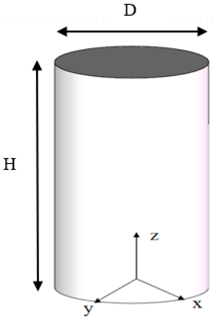
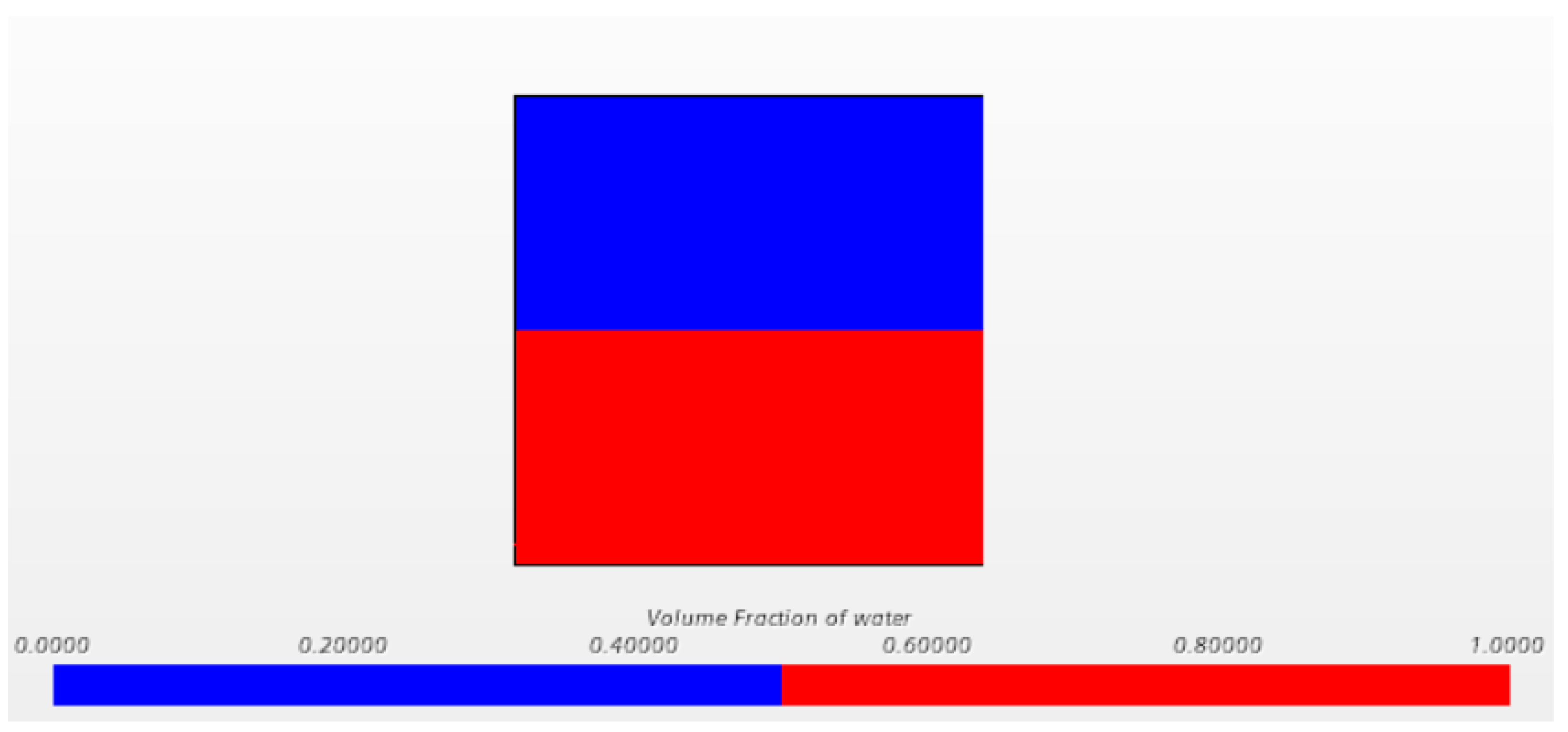
In order to verify the accuracy of the model and numerical method in this paper, the natural frequency of the liquid tank swing in the cylindrical container was numerically simulated, and the numerical results were compared with results from the literature and theoretical values. The three-dimensional cylindrical liquid tank in Pan Lijian (2007) [32] was selected for the model, and the dimensions of the cylindrical container are shown in Table 1: the diameter of the container was D = 0.6 m, the radius was R = 0.3 m, the height H = 0.6 m, the thickness of the container wall was d = 0.01 m, the medium inside the container was water, and the free liquid-level height was h = 0.3 m when the liquid was stationary. The turbulent flow model is used for the computational model, the VOF model is used for multiphase flow, the implicit unsteady solver is used for the iterative method, and the second-order time discrete format is selected. The top is set to the pressure outlet, and the rest of the faces are all set to non-slip walls. A model of the cylindrical liquid tank and the free liquid-level contour of the liquid at rest are shown in Figure 1 and Figure 2.

Table 1.
Dimensions of the cylindrical tank model.

Figure 1.
Cylindrical fluid tank model.

Figure 2.
Still free-surface cloud map.
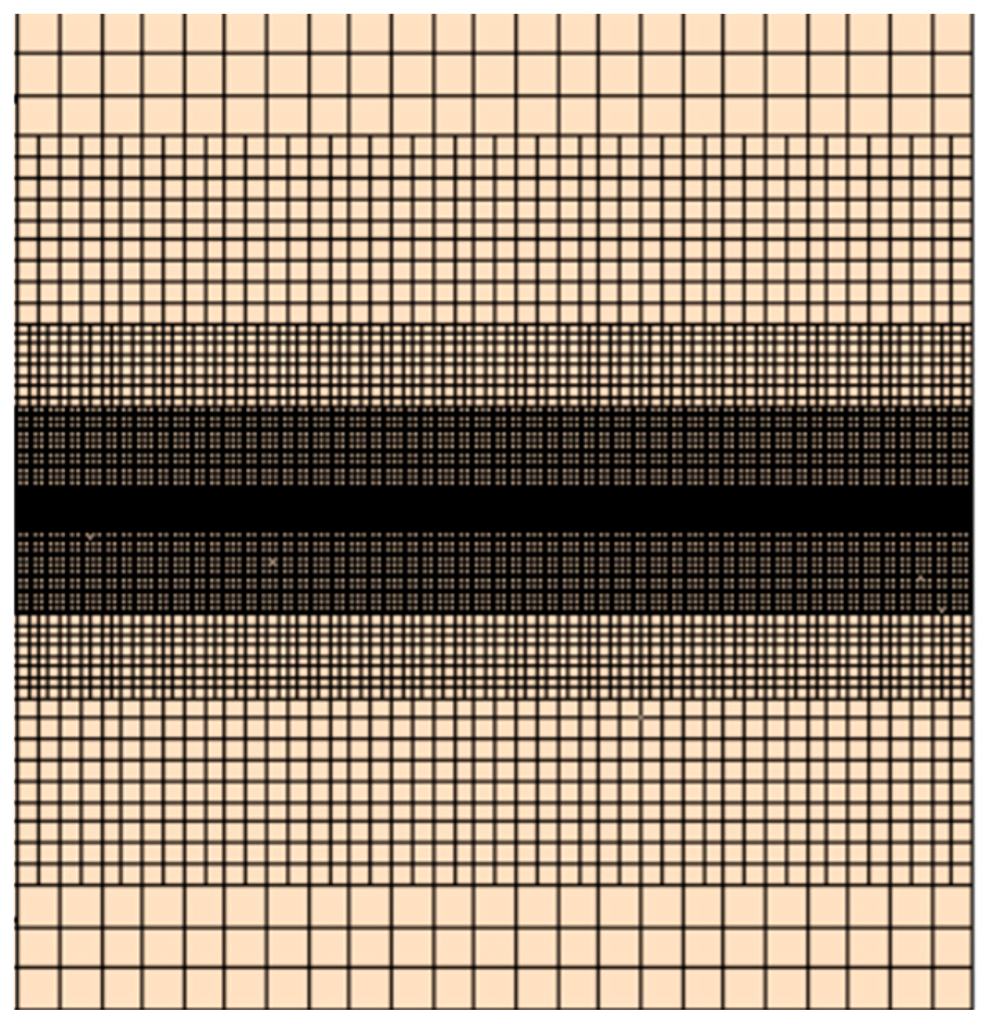
In this example, the meshing submodel of the surface reconstruction and cutting body mesh generator in STAR-CCM+ are adopted, and two layers of volume control are used to encrypt when the free liquid surface is shaking and when the liquid surface is close to stationary to ensure accurate capture of the waves; the surface reconstruction can optimize the surface shape of the liquid tank and facilitate the generation of volume meshes, as shown in Figure 3.

Figure 3.
Schematic diagram of mesh (X-Z plane).
3.2. Grid Convergence Analysis
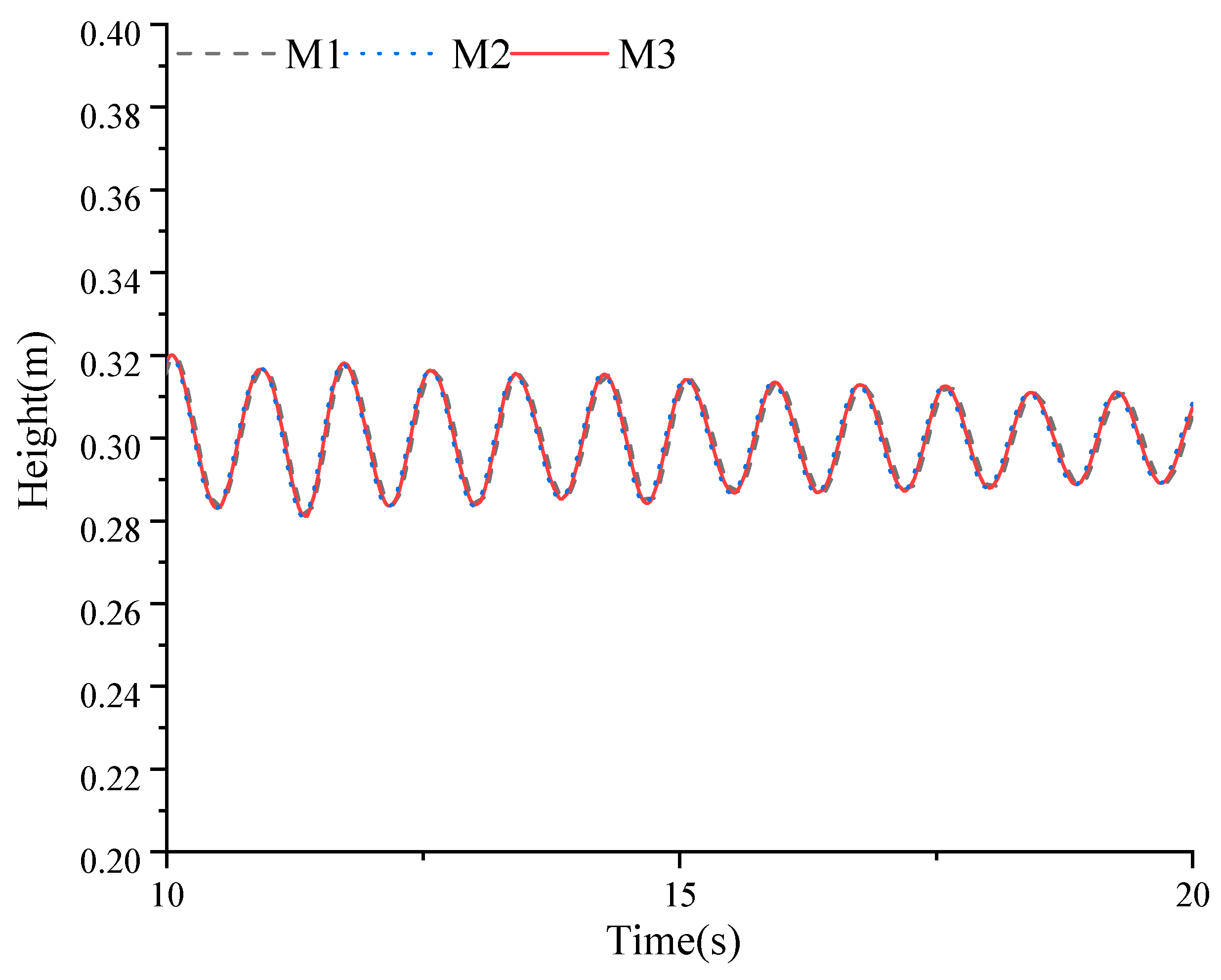
In this section, the grid is divided into 20 grids in the direction of the wave height of the free liquid surface, and the grid density encryption is carried out at two free liquid surfaces; the three grid sizes of 0.025 m, 0.027 m, and 0.03 m are analyzed for convergence analysis; the specific size information of the three grid schemes is shown in Table 2.
Table 2.
Grid size settings.
Figure 4 shows the time history curves of the wave height at the left bulkhead of the cylinder fluid tank for the three different grid sizes. As can be seen from the figure, the meshes M2 and M3 can still converge in the initial stage (10–20 s) relative to the fine mesh M1. There is little difference between the wave simulation results of the grid schemes M1 and M2, and in general, the numerical results under the three grid schemes are approximately consistent.

Figure 4.
The wave elevation curve of left bulkhead for different grid sizes (10–20 s).
Table 3 shows an analysis of the average peak error of the left bulkhead wave height under the different grid schemes. As can be seen from the table, the relative error of both grids M2 and M3 does not exceed 5% relative to the fine grid M1. The results of the grid convergence analysis show that the liquid sloshing amplitude of the STAR-CCM simulated cylindrical liquid tank model is not sensitive to the grid size, and the numerical simulation results under the three grid sizes are very reliable. In order to ensure the accuracy of the numerical calculations and account for the limitation of computing resources, the M2 grid scheme was selected for the meshing of the liquid tank.
Table 3.
The average peak of left bulkhead wave height for different grid sizes.
3.3. Time-Step Convergence Analysis
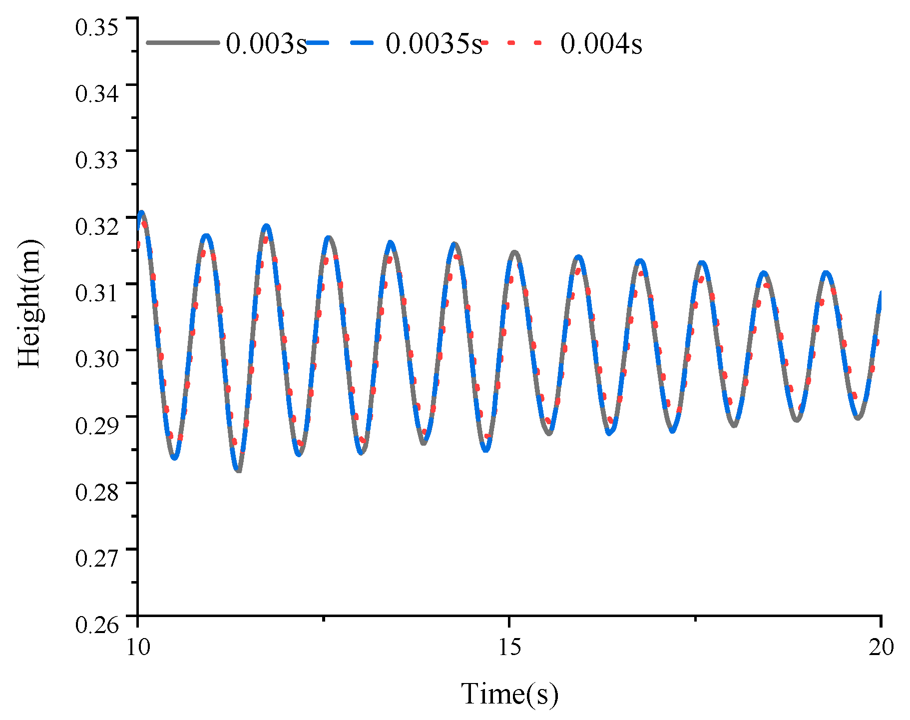
The choice of time-step size determines the level of calculation accuracy and the consumption of computing resources, and grid scheme M2 was analyzed and selected in this section to carry out a study of the influence of time-step size on the convergence of the calculation results; a total of three time steps were set, which are 0.003 s, 0.0035 s, and 0.004 s; the curves of the wave heights for the three different time steps with the time step are shown in Figure 5.

Figure 5.
The wave elevation curve of left bulkhead for different time steps (10–20 s).
According to the information analysis in Table 4, it can be seen that the wave surface at the left bulkhead of the liquid tank gradually stabilizes and attenuates, and the average amplitude error of the two is 0.03% when the numerical calculation time step is 0.035 s and 0.003 s, and the relative error is slightly larger, at 0.38%, when the calculation time step is 0.004, and the errors of the three calculation results are within the allowable range, indicating that the numerical calculation models of the three time steps have reached convergence. Considering the stability of the calculation results and the calculation cost, the calculation time step of 0.0035 s was chosen.
Table 4.
Average peak of left bulkhead wave height for different time steps.
3.4. Verification and Analysis of the Accuracy of the Numerical Model of Liquid Tank Sloshing
The natural frequency of the tank does not change with the external conditions, it is an inherent property of the tank, and it is only related to the shape and depth of the tank. Please check meaning retained In order to verify the accuracy of the numerical method of simulating liquid tank sloshing in this paper, the numerical calculation results in this paper are compared with the theoretical values of the empirical formula of the natural frequency of a partially filled cylinder liquid tank derived from Pan Lijian’s study and Franklin T Dodge (2000) [32,33], so as to verify the accuracy of the numerical calculation results in this paper. The formula for calculating the natural frequency of the cylinder fluid tank is as follows:
where h is the depth of the liquid at rest, R is the radius of the cylinder, n is the order of the wave, and g is the acceleration due to gravity. is the circular frequency; when n is 1, it corresponds to the first-order natural frequency, and when n is 2, it corresponds to the second-order natural frequency.
When a partially filled container is disturbed by an external force or is subjected to a transient horizontal excitation at the initial moment, the liquid in the tank shakes. For example, the tank suddenly accelerates or gives the liquid in the tank an initial wave shape at the initial moment, allowing it to swing freely under gravity. In this section, the natural frequencies of the liquid in a three-dimensional cylindrical fluid chamber are verified by numerical simulation, setting the initial wave surface to the first-order mode shape; the initial wave surface parameters are shown in Table 5.
Table 5.
Initial wave surface parameter.
In Table 5, 0.03 is the amplitude, x is the position coordinate along the length, and L is the length in the x-direction.
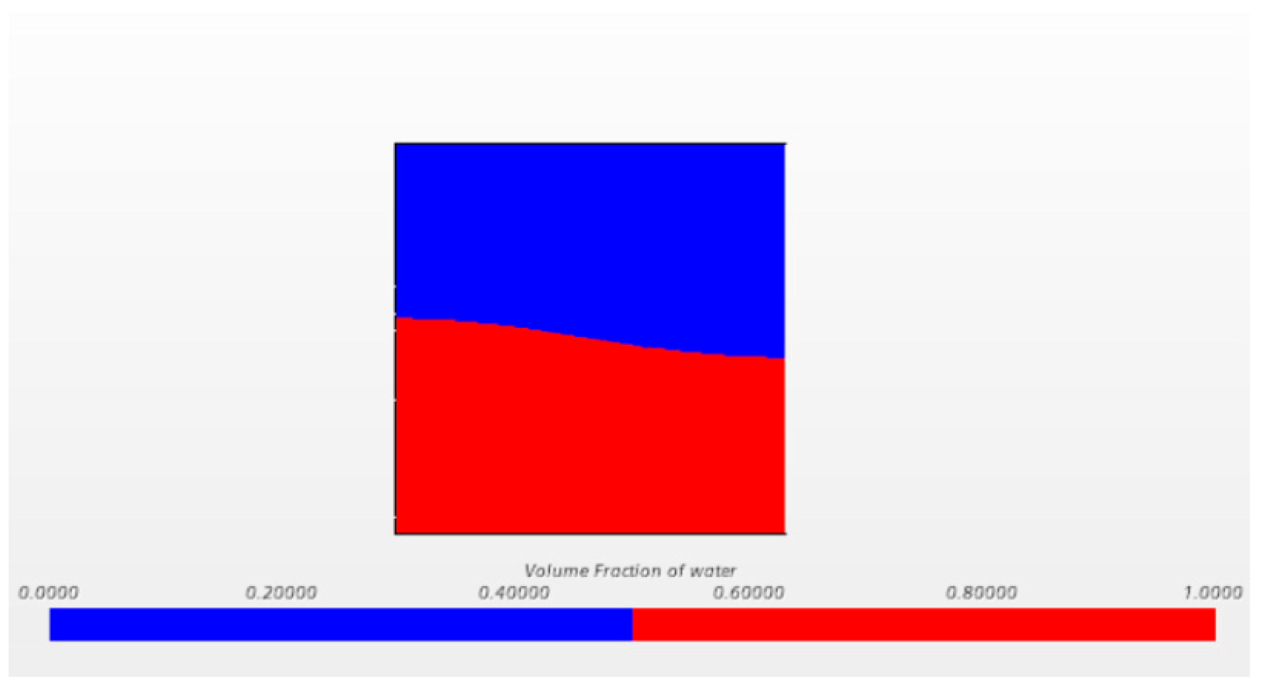
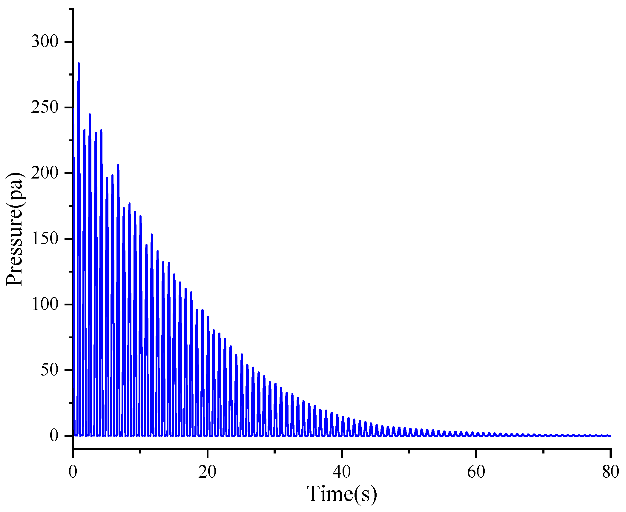
The three-dimensional cylinder liquid tank sloshing simulation was carried out by using the STAR-CCM+ software, and the initial conditional volume fraction field function was set by the STAR-CCM+ user-defined field function, and a schematic diagram of the initial free liquid level, as shown in Figure 6, was obtained. The initial wave surface moves freely, attenuating at its natural frequency under the action of gravity; a high free attenuation curve at the left bulkhead wave under the condition of the initial first-order mode shape wave surface is obtained, as shown in Figure 7, and the pressure change curve at the center point of the left bulkhead is shown in Figure 8.

Figure 6.
Visualization cloud diagram of free surface.

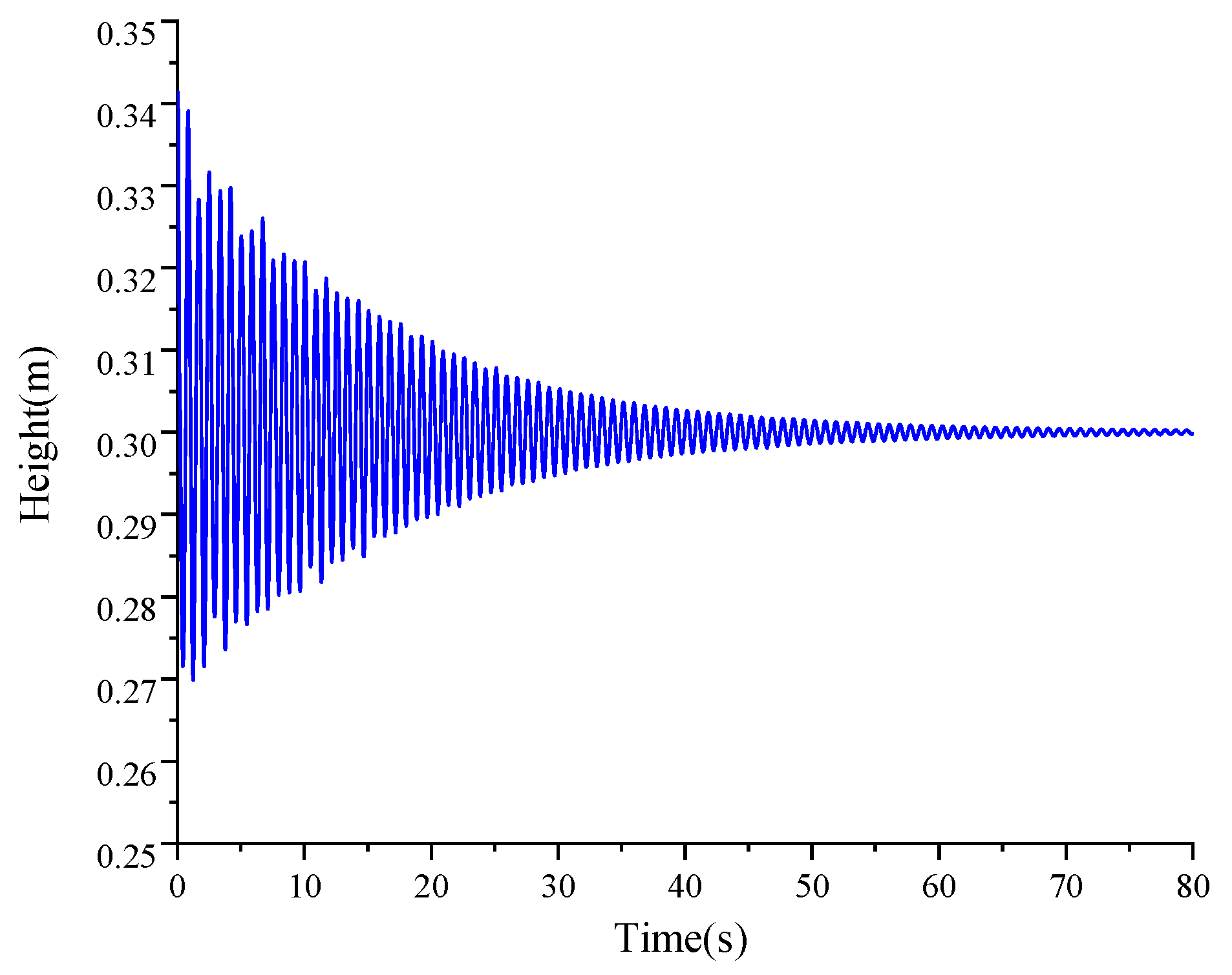
Figure 7.
The wave elevation curve of left bulkhead.

Figure 8.
Pressure curve at center point of left bulkhead.
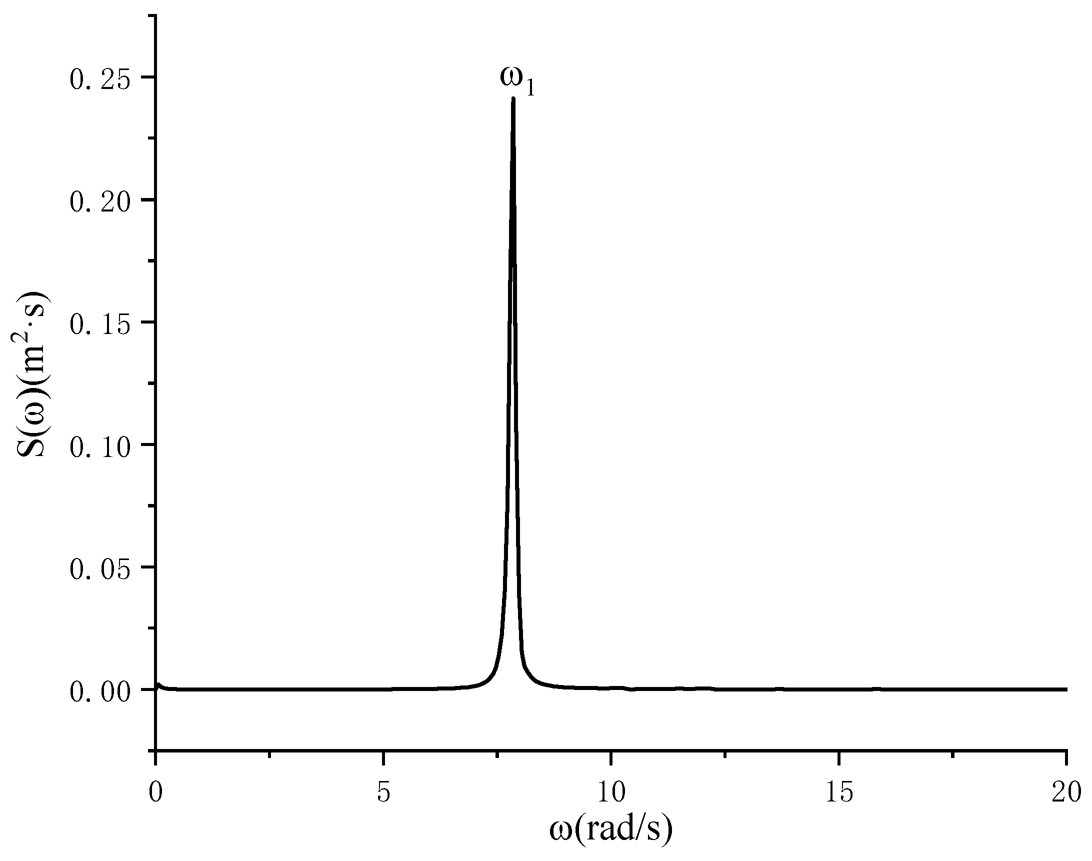
A Fourier transform analysis was carried out on the elapsed curve of the wave height at the left bulkhead, and then according to the spectral density formula, the energy spectrum shown in Figure 9 was obtained. The formula for spectral density is
where is the amplitude value obtained by the Fourier transform.

Figure 9.
Energy spectrum.
It is evident from the graph that there is a distinct peak in the energy spectrum, which corresponds to a first-order natural frequency of 7.56 rad/s. The numerical results are compared with the theoretical values obtained by the empirical formula and the median values in the relevant literature, and the error results obtained by the analysis are shown in Table 5. The formula for calculating the error of the natural frequency is
According to the analysis in Table 6, the error between the calculated results and the theoretical values in this paper is 3.83%, while there is almost no error compared to the calculation results in the related literature, indicating that the numerical model can simulate the first-order wave surface sway problem in the cylindrical fluid tank well, and at the same time can maintain good accuracy, which provides strong support for the following research on the anti-sway effect of the damping plate in the cylindrical fluid tank.
Table 6.
Relative error analysis of natural frequency.
4. Analysis of the Effect of the Damping Plate on Suppressing Sloshing in the Liquid Tank
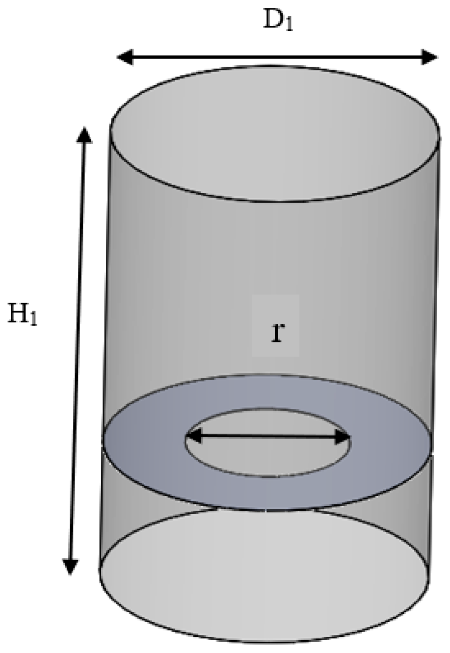
The numerical simulation of the cylindrical liquid tank has been verified above, and this subsection takes the hypothetical cylindrical liquid tank in the column of the maritime satellite launch platform as the research object. As shown in Table 7, the diameter of the cylindrical liquid tank D1 is 10.18 m, the height of the cylindrical liquid tank H1 is 10.9 m, the water filling volume in the liquid tank is 50%, and the free liquid level height is 5.45 m when stationary. In order to study the inhibition effect of the damping plate on the wave surface sloshing in the cylinder liquid tank, an open-hole damping plate with a thickness of 0.03 m was designed: the diameter of the damping plate was the same as that of the cylinder, the opening position was located at the center of the circle, the aperture was r = 5.09 m, and the damping plate was one fifth of the height of the stationary free liquid surface. As shown in Figure 10, the model compares the wave surface sloshing of the liquid tank with and without damping plates to verify the inhibition effect of the damping plates on the sloshing in the liquid tank.
Table 7.
Dimensions of the cylindrical tank model with baffles.

Figure 10.
Cylindrical fluid tank model with baffle.
In STAR-CCM+, the physical model is defined based on the physical continuum. For a 3D model, 3D is first selected. The sloshing of the liquid in the tank is an unsteady flow, so the implicit unsteady time solver is chosen. Since there are two fluids in the tank, water and air, the Eulerian multiphase flow is selected to define the fluid, and the fluid domain volume model is further selected. For viscous fluids, the choice of laminar and turbulent flow depends on the Reynolds number. In this example, a turbulence model is used for the simulation, and gravity is selected to generate traveling waves. The pressure near the free surface in the initial conditions is set at a standard atmospheric pressure of 101,325 Pa.
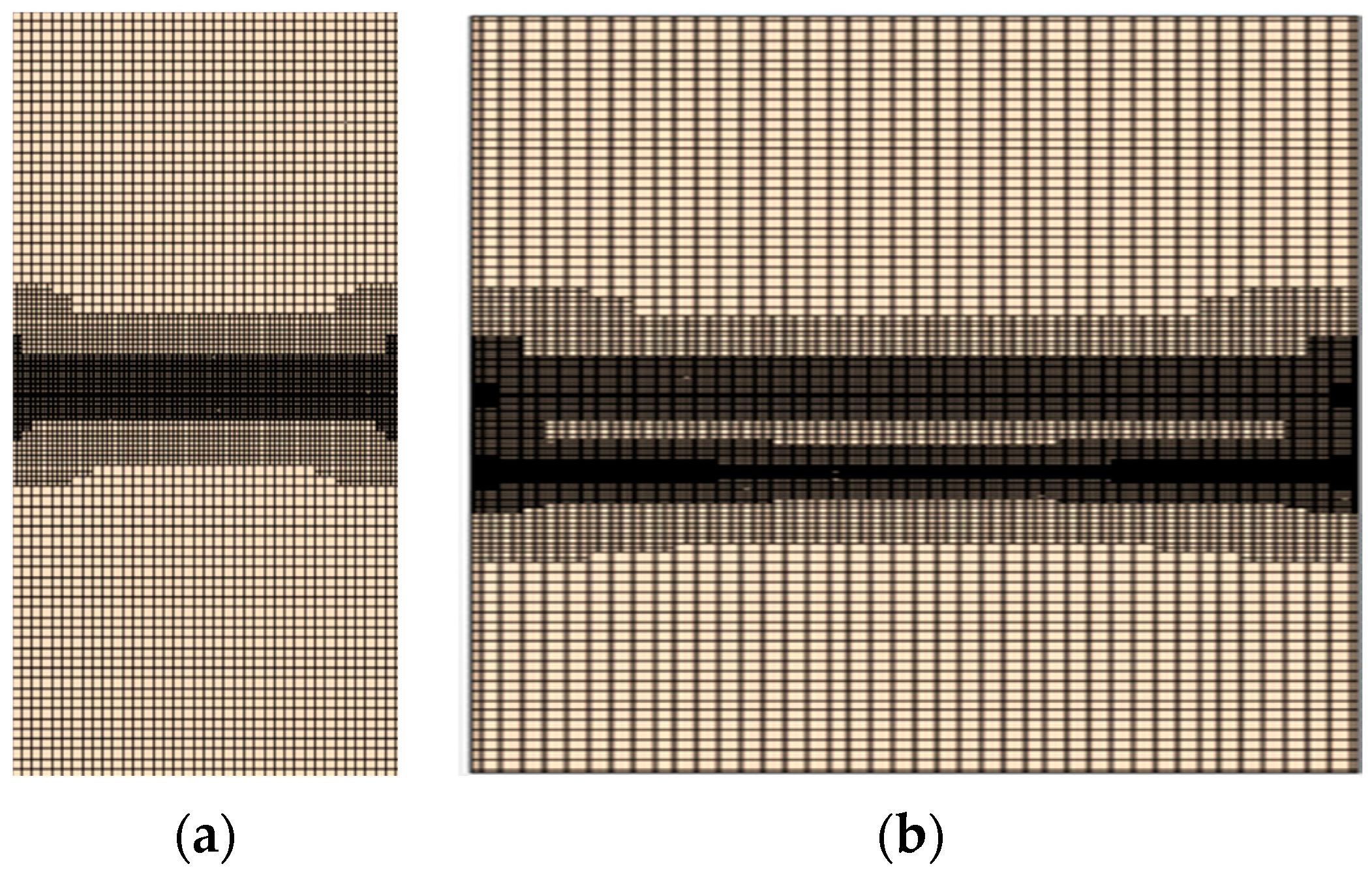
Based on the time step of 0.0035 s chosen in Section 3.3 and the meshing method chosen in Section 3.2, this subsection uses the meshing submodel of surface reconstruction and cutting body mesh generator in STAR-CCM+, and uses three-layer volume control to encrypt the vicinity of the free liquid surface sloshing, the stationary place of the free liquid level, and the vicinity of the damping plate to ensure the accuracy of wave capture, and the basic mesh size of the 3D column liquid tank model is set to 0.25 m. The meshing is shown in Figure 11.

Figure 11.
Schematic diagram of mesh (X-Z plane). (a) No damping plates; (b) With plate damping.
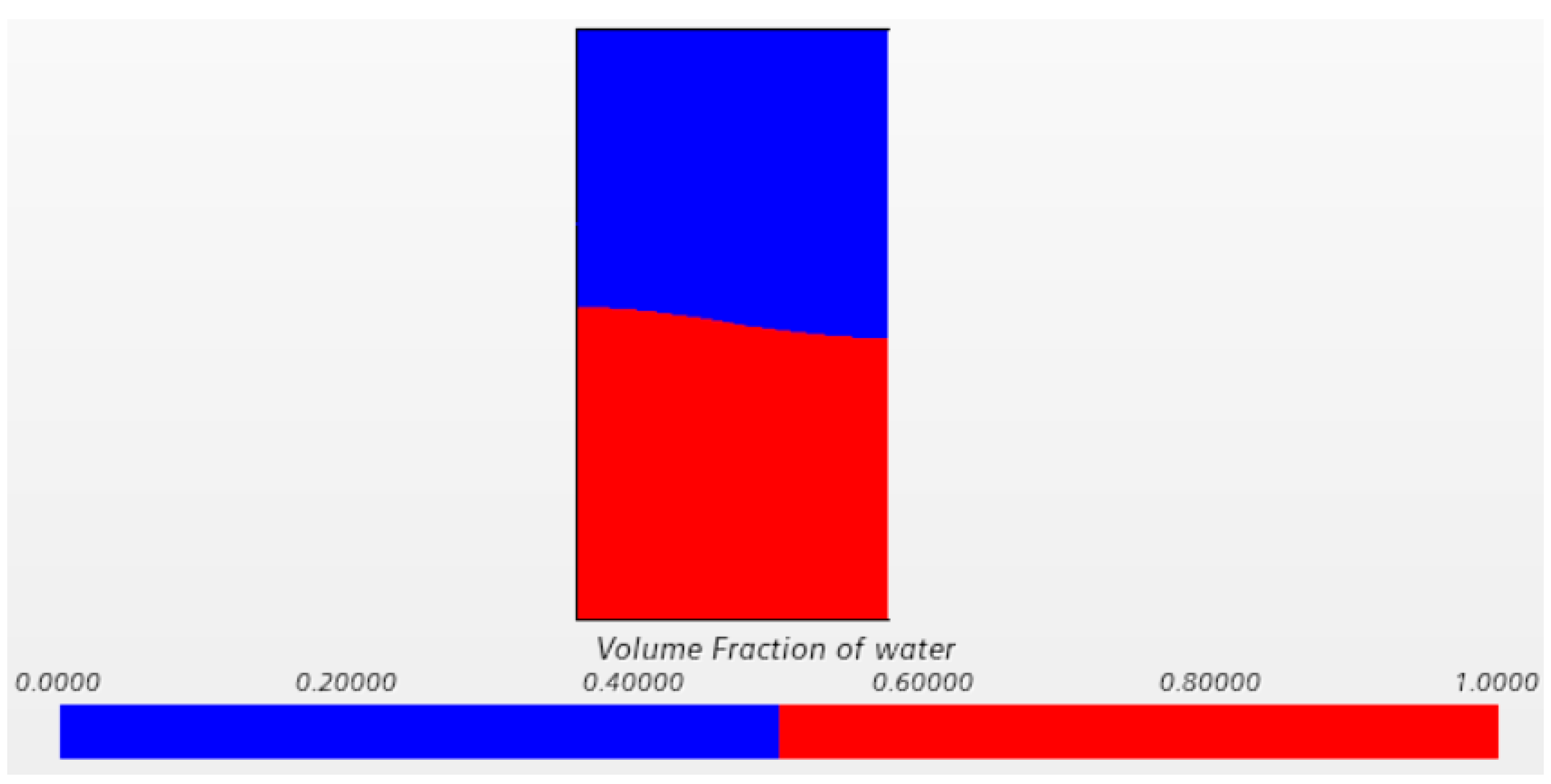
This section still initiates the fluid motion by defining the initial wave surface within the tank via a newly created field function at time zero, thereby enabling observation of the free sloshing damping characteristics. When the liquid in the liquid tank of the three-dimensional cylindrical column is at rest, the free liquid level is half of the height of the column, that is, 5.45 m, and the liquid filling rate is 50%; the volume fraction scalar contour is used to record the shaking of the liquid in the liquid tank, as shown in Figure 12.

Figure 12.
Visual cloud map.
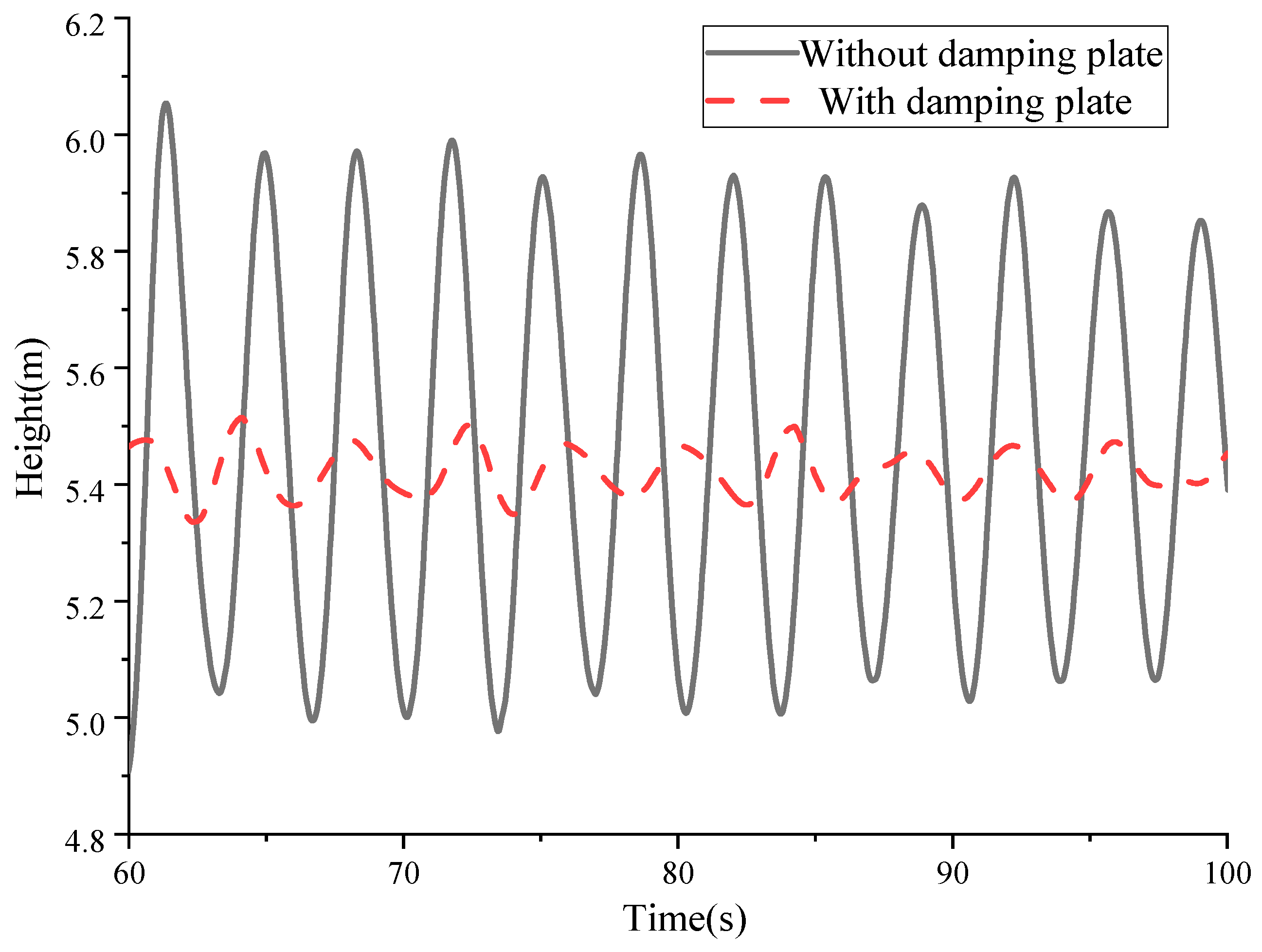
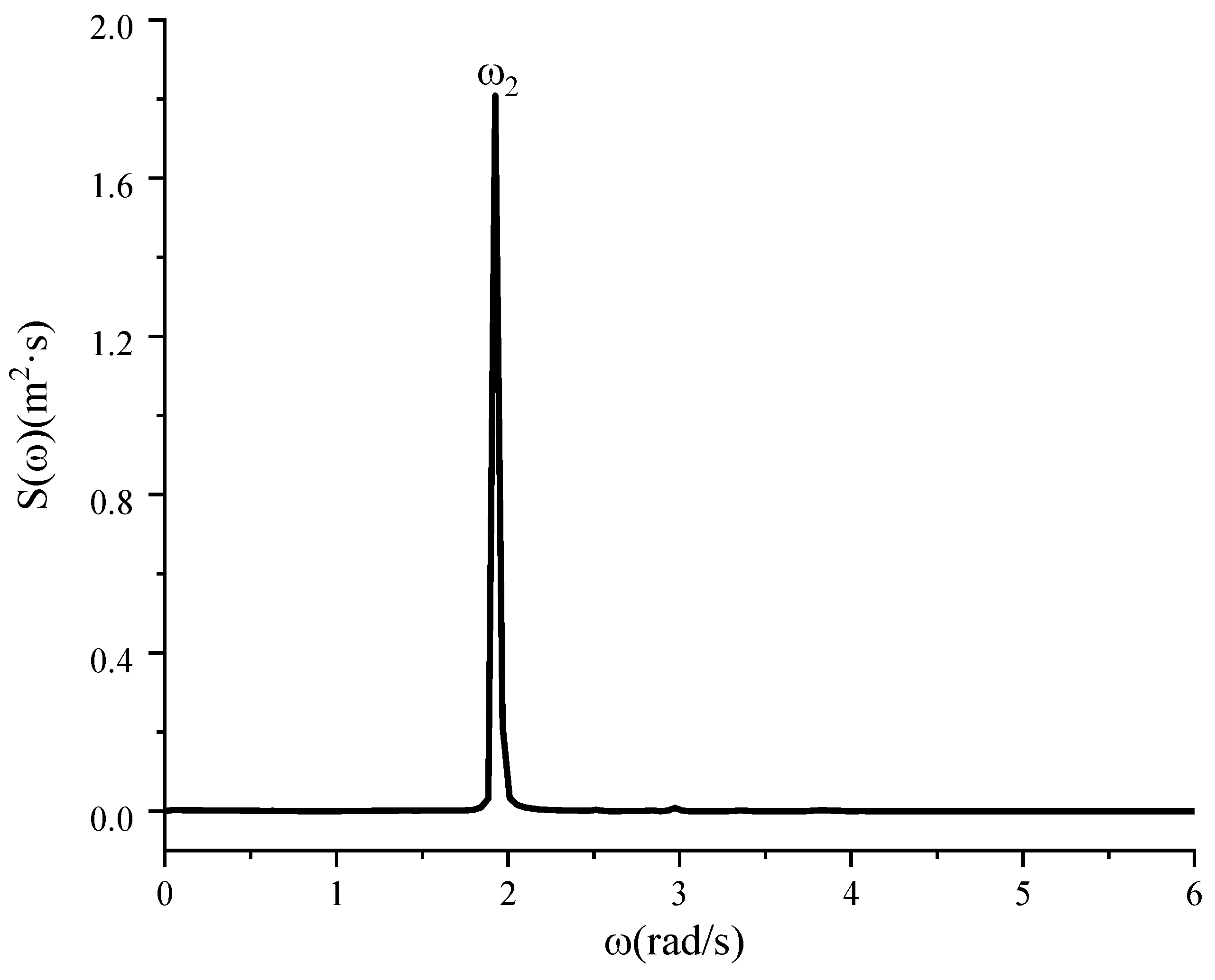
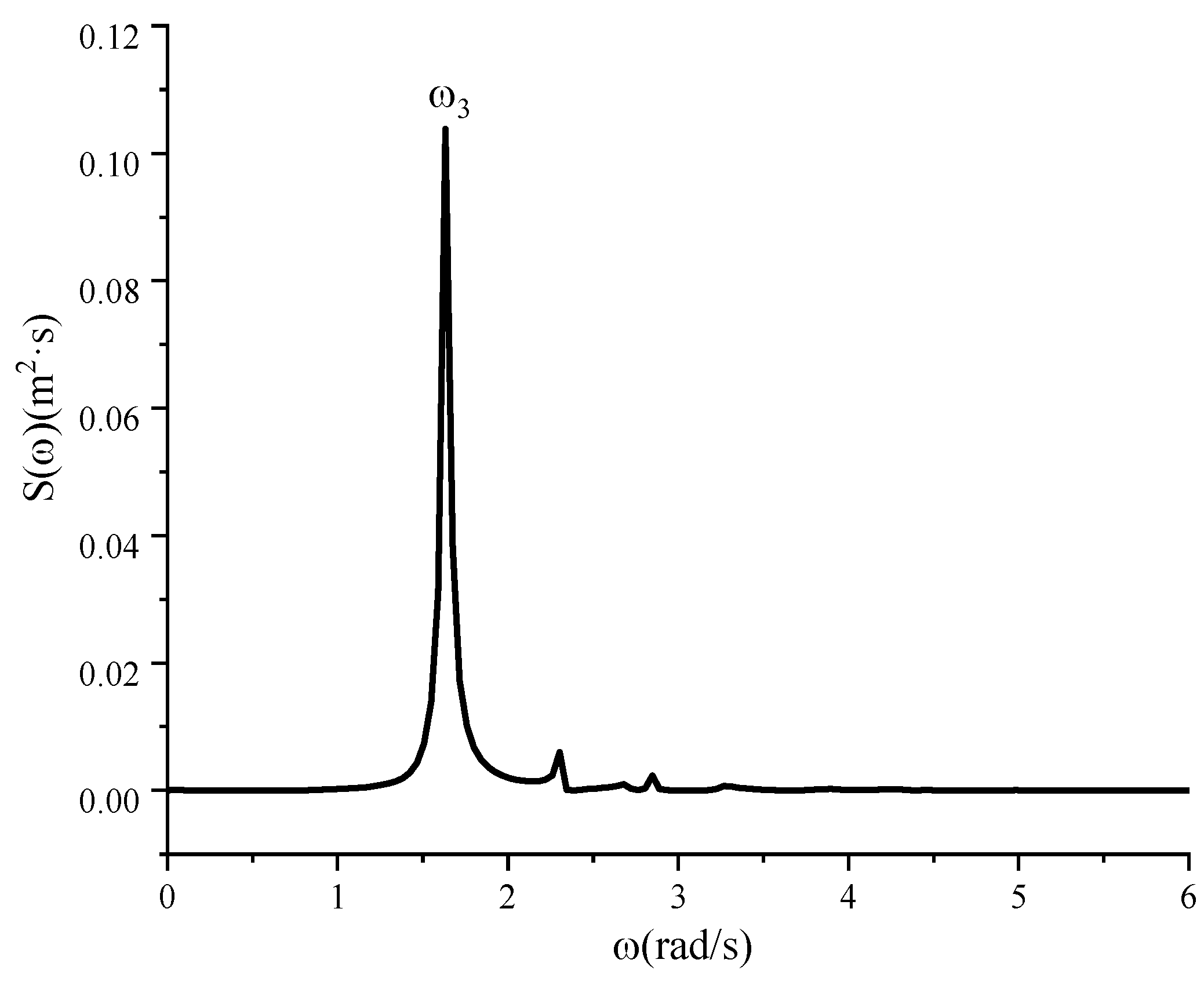
Figure 13 is the diachronic curve of the wave height change at the left bulkhead with and without a damping plate, and the analysis of the information in the diagram shows that the liquid-level height in the liquid tank gradually decays with time, and the liquid-level height attenuation is particularly obvious after adding the damping plate. After 60–100 s of wave surface attenuation, the average amplitude of the liquid surface without the damping plate is 0.941 m, and the average amplitude of the liquid surface during this period is 0.097 m after adding the damping plate, and the wave surface attenuation amplitude can reach 89.69%, indicating that the damping plate can effectively suppress the liquid shaking in the cylindrical liquid tank, and at the same time make the wave surface reach a calm state quickly. The reason for this analysis is mainly due to the interference effect of the damping plate on the movement of the water quality point of the wave surface, which accelerates the energy consumption of the wave surface, and the addition of the damping plate also changes the natural frequency of the liquid tank. A Fourier transform was carried out on the diachronic curve of the wave height change at the left bulkhead of the liquid tank with or without a damping plate; from the energy spectrum obtained by the Fourier transform on the wave height change curve at the left bulkhead in the case of the damping plate, as shown in Figure 14 and Figure 15, it can be seen that the natural frequency of the first-order sloshing of the wave in the liquid tank without a damping plate is 1.926 rad/s, and the natural frequency of the first-order sloshing is 1.643 rad/s after adding the damping plate. This shows that the addition of the damping plate can change the natural frequency of the liquid sloshing in the liquid tank, reduce its movement, and achieve an inhibition effect; and the main reason for the reduction in the shaking amplitude of the damping plate is the increase of physical dissipation.

Figure 13.
The wave elevation curve of left bulkhead with and without baffle.

Figure 14.
The energy spectrum of left bulkhead wave height variation duration curve without baffle.

Figure 15.
The energy spectrum of left bulkhead wave height variation duration curve with baffle.
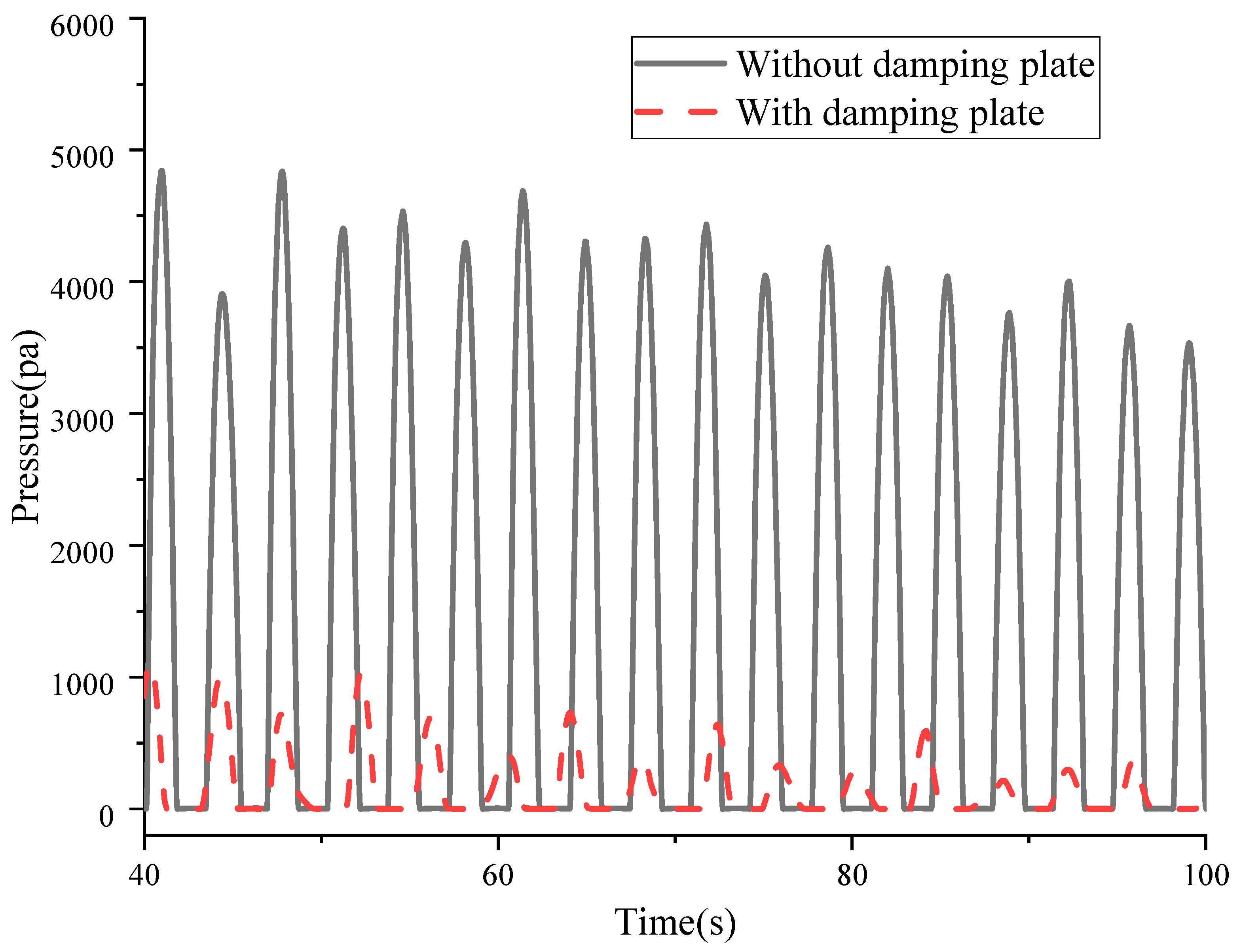
Figure 16 is the pressure change curve of the center point of the left bulkhead with and without the damping plate, and the information in the diagram shows that the pressure on the left bulkhead in the liquid tank gradually decreases with the time after the beginning of liquid sloshing. After 40–80 s, the maximum pressure on the left bulkhead without the damping plate is 4837.96 Pa, and the maximum pressure on the left bulkhead with the damping plate is 1104.20 Pa; it can be clearly seen that the pressure on the left bulkhead is significantly reduced after adding the damping plate, which is due to the addition of the damping plate suppressing the shaking of the wave surface, thereby reducing the impact force on the bulkhead and improving the stability.

Figure 16.
Pressure curve at center point of left bulkhead with and without baffle.
5. The Influence of the Position of the Damping Plate on the Sloshing in the Liquid Tank
5.1. Damping Separator Parameters
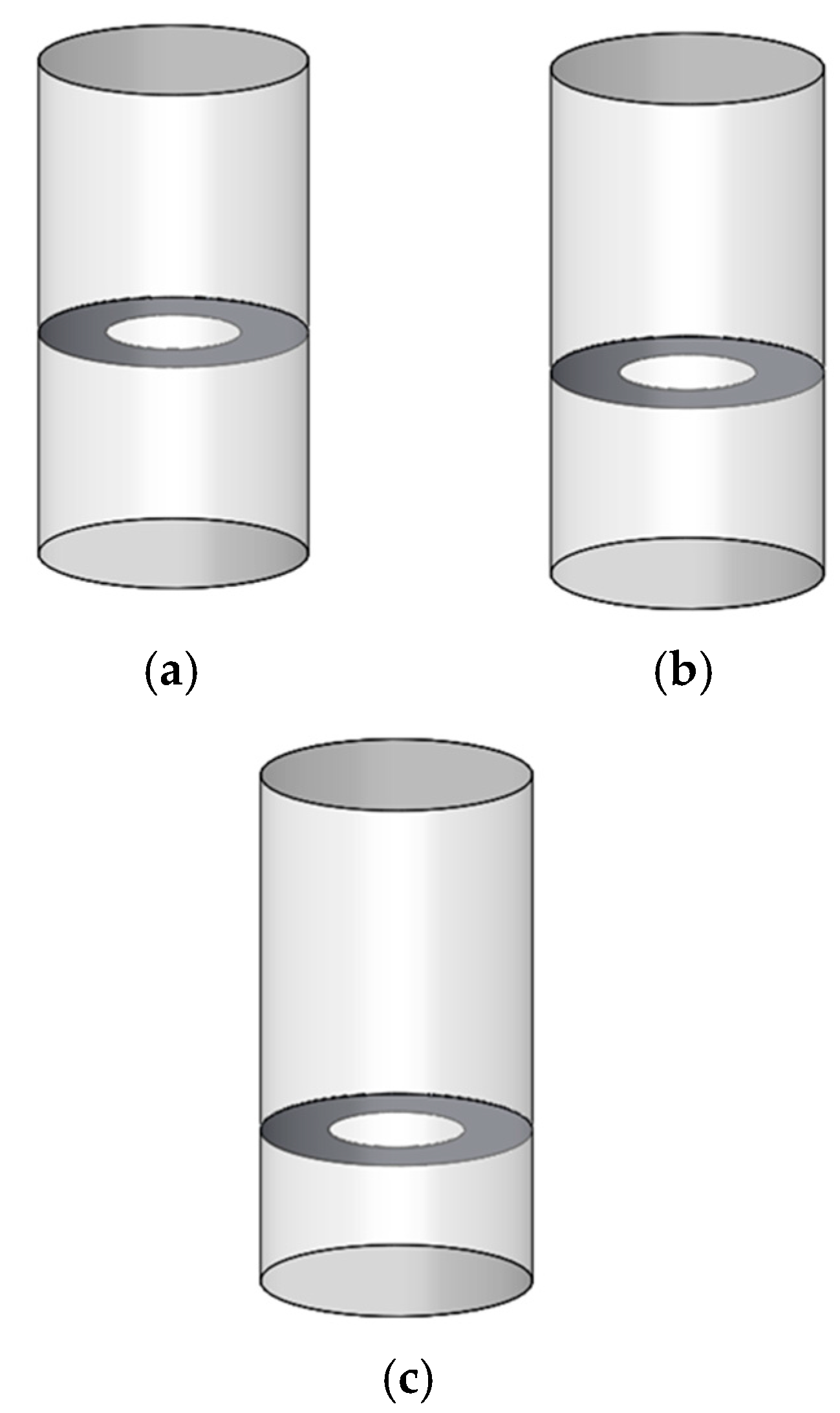
In order to study the inhibition of sloshing in the liquid tank when the damping plate is placed at different heights, the inhibition effect of the damping plate at three different positions in the liquid tank was numerically calculated. The initial static water-level height of the liquid tank is H2, the height of the upper surface of the damping plate from the stationary water surface is h1, and the design damping partition is located at h1/H2 = 1/10, h1/H2 = 1/5, h1/H2 = 2/5; the specific position layout of the damping plate is shown in Figure 17.

Figure 17.
Layouts of different baffles. (a) h1/H2 = 1/10; (b) h1/H2 = 1/5; (c) h1/H2 = 2/5.
5.2. The Influence of Damping Plates in Different Positions on the Amplitude and Pressure in the Liquid Tank
In order to analyze the suppression effect of the damping plate on the wave surface sloshing in the liquid tank, this subsection compares the wave height elapsed curves and the pressure at the left bulkhead in the liquid tank for three different damping plate positions, and then obtains the average amplitude and maximum pressure in the liquid tank at three different damping plate positions, so as to analyze the difference in the damping plate position on the sway suppression effect in the liquid tank.
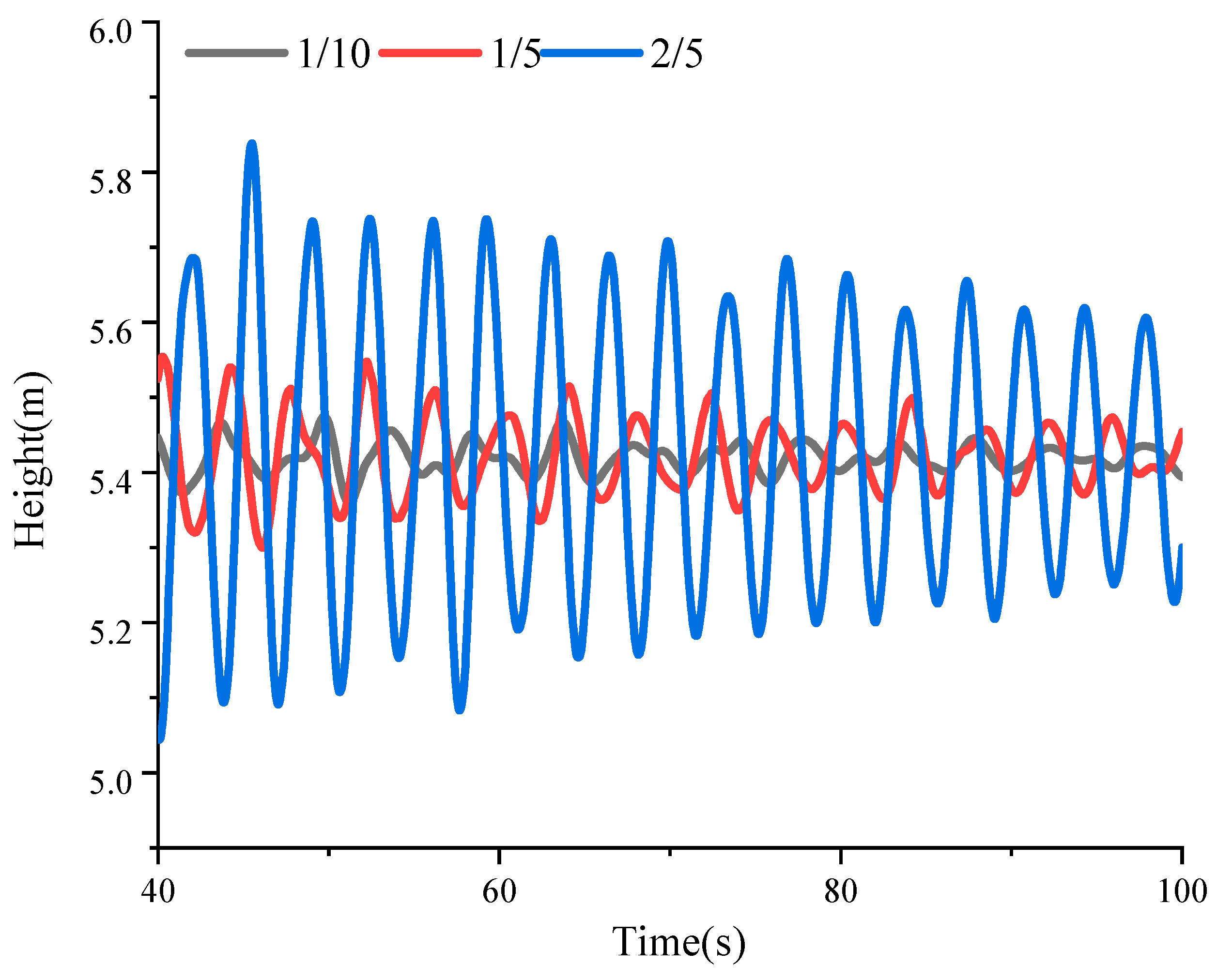
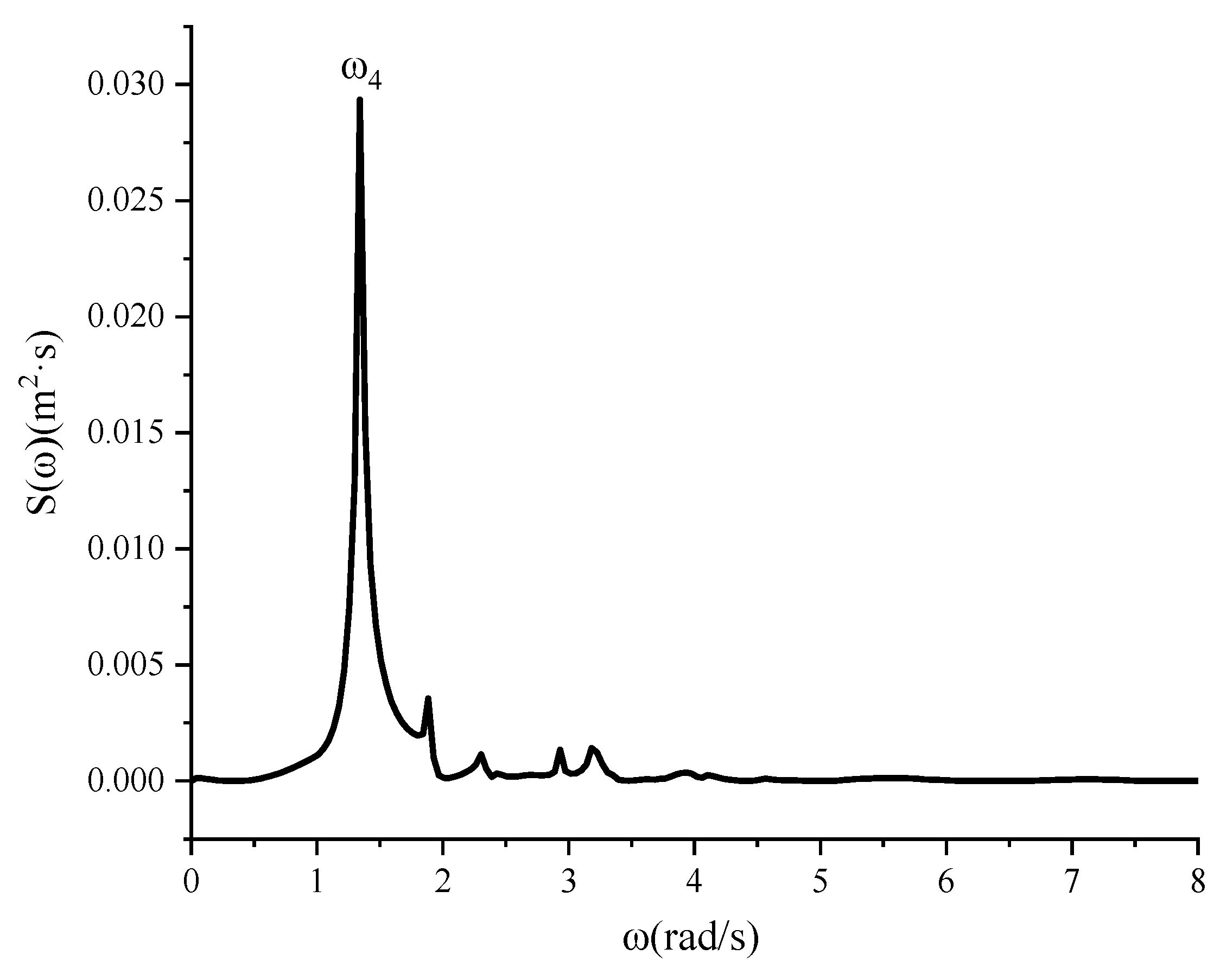
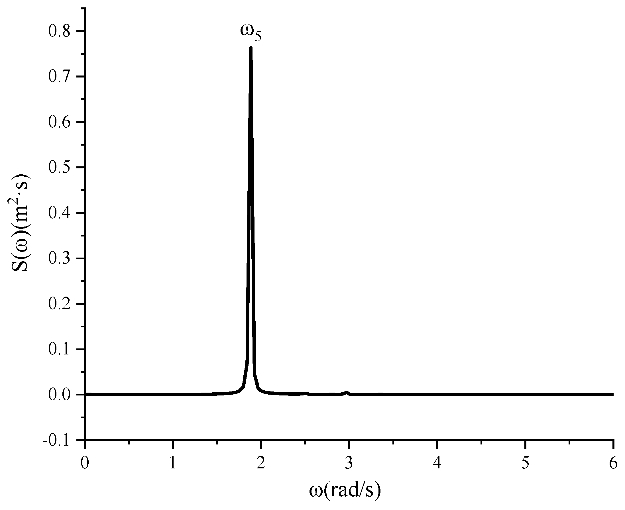
Figure 18 is the elapsed curve of the wave height change at the left bulkhead under different damping plate positions for 40–100 s; the information in the analysis diagram shows that as time passes, the liquid-level height in the liquid tank gradually attenuates, and at the same time, when the damping plate is away from the liquid-level heights h1/H2 = 1/10 and h1/H2 = 1/5, the free liquid level attenuation is obvious: the wave amplitude is small and close to stable. From the graph analysis, it can be seen that when h1/H2 = 1/10, the average wave amplitude is 0.0497 m, and when h1/H2 = 1/5, the average amplitude is 0.0977, and the average amplitude difference is about 0.048 m, which indicates that when the damping plate is close to the liquid level, the closer the damping plate is to the liquid level, the higher its inhibition effect on the liquid sloshing in the liquid tank, but the lifting effect is smaller; when the damping plate is located at h1/H2 = 2/5, it is obvious from the figure that the wave surface amplitude is larger, compared with h1/H2 = 1/5 and h1/H2 = 1/10. The damping plate has a poor inhibitory effect on the liquid sloshing in the liquid tank, and the average amplitude is 0.5223 m. The reason for this is mainly due to the fact that when the liquid in the liquid tank is shaken by the first-order wave surface, the energy of the liquid shaking is mainly concentrated near the wave surface; when the damping plate is close to the wave surface, the wave surface can interact with the damping plate, consume the water quality point energy of the wave surface, and destroy the wave surface movement. Figure 19 and Figure 20 show the first-order-shaking energy spectrum of the liquid tank wave surface when the damping plate is arranged at h1/H2 = 1/10 and h1/H2 = 2/5, and it can be seen from the figure that when the position of the damping plate is h1/H2 = 1/10, the natural frequency of the liquid surface sloshing in the tank is 1.341 rad/s, which is quite different from the natural frequency of the first-order wave surface sloshing without the damping plate, indicating that the wave surface motion has been significantly reduced, making it reach a stable state earlier. When the position of the damping plate is h1/H2 = 2/5, the natural frequency of the liquid-level swing in the liquid tank is 1.884 rad/s, which is less different from the natural frequency of the first-order wave surface swing without the damping plate, which indicates that the interference of the damping plate arranged at this position on the movement of the liquid surface is small, and the suppression effect is poor when the damping plate is far away from the wave surface.

Figure 18.
The wave elevation curve of left bulkhead at different baffle heights.

Figure 19.
Energy spectrum of left bulkhead wave height variation duration curve (h1/H2 = 1/10).

Figure 20.
Energy spectrum of left bulkhead wave height variation duration curve (h1/H2 = 2/5).
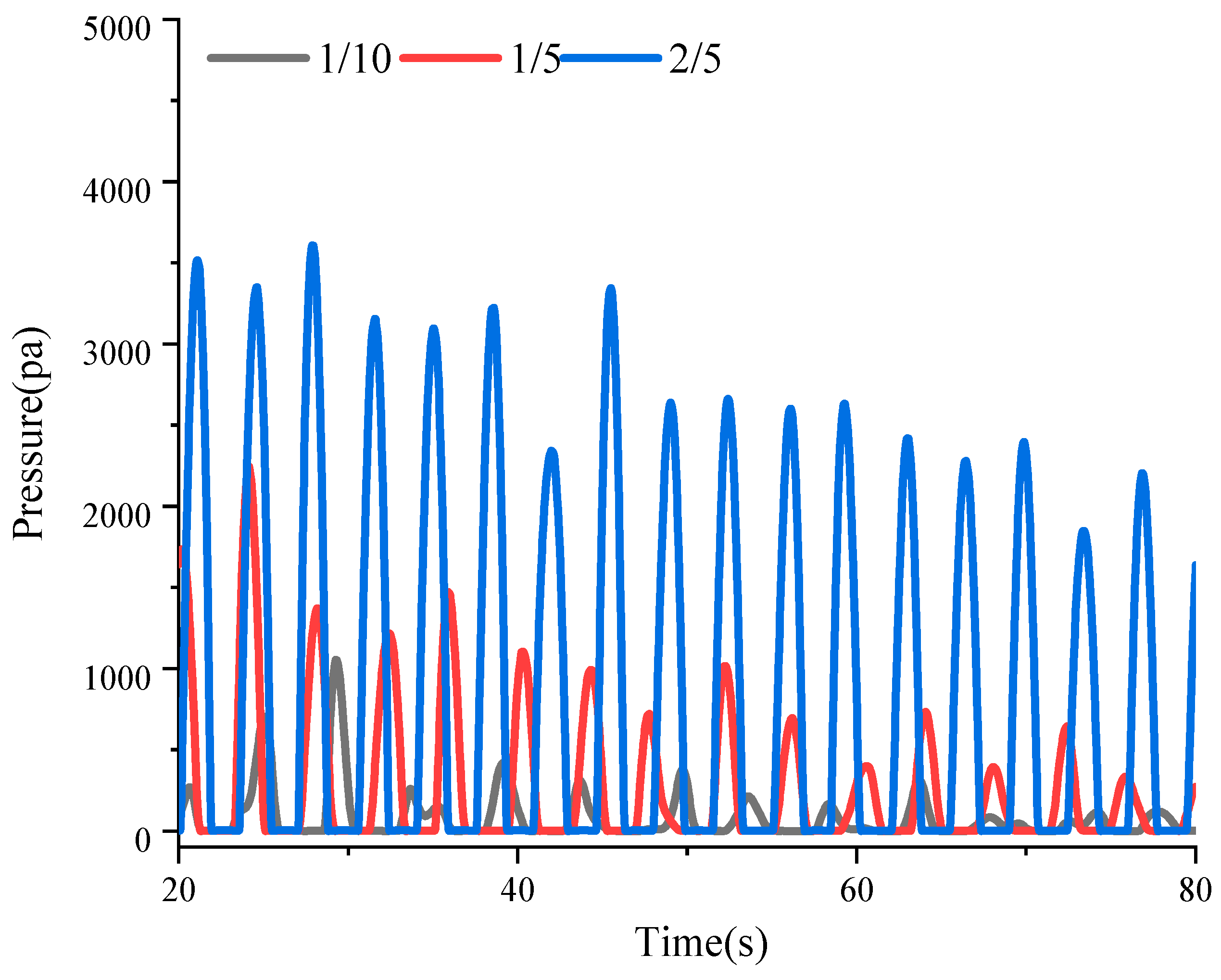
Figure 21 is the curve of pressure change at the center point of the left bulkhead under different damping plate positions between 20 and 80 s, and the figure shows that as time passes the pressure of the left bulkhead of the liquid tank gradually decreases, which is similar to the phenomenon of liquid swing amplitude in the liquid tank, and when the damping plate is arranged at the height h1/H2 = 1/10, because the liquid level is close to stability, the pressure change amplitude at the left bulkhead caused by the wave surface is small, almost zero; when the damping plate arrangement height h1/H2 = 1/5, the left bulkhead is still subjected to a certain pressure because the liquid in the liquid tank still has a small-amplitude oscillation, and its maximum value is 2246.4 Pa; when the damping plate is arranged at the height h1/H2 = 2/5, the left bulkhead of the liquid tank is subjected to a large impact because the liquid tank shake is less disturbed by the damping plate, the wave surface sloshing attenuation is smaller, and the left bulkhead of the liquid tank is subjected to a larger impact. The maximum pressure is 3608.1 Pa, which indicates that the damping plate is arranged near the wave surface, which can effectively reduce the force at the bulkhead, reduce the impact on the liquid tank, and improve its stability and safety.

Figure 21.
Pressure curve at center point of left bulkhead at different baffle heights.
6. The Influence of the Damping Plate Type on the Sloshing in the Liquid Tank
6.1. Damping Partition Parameters
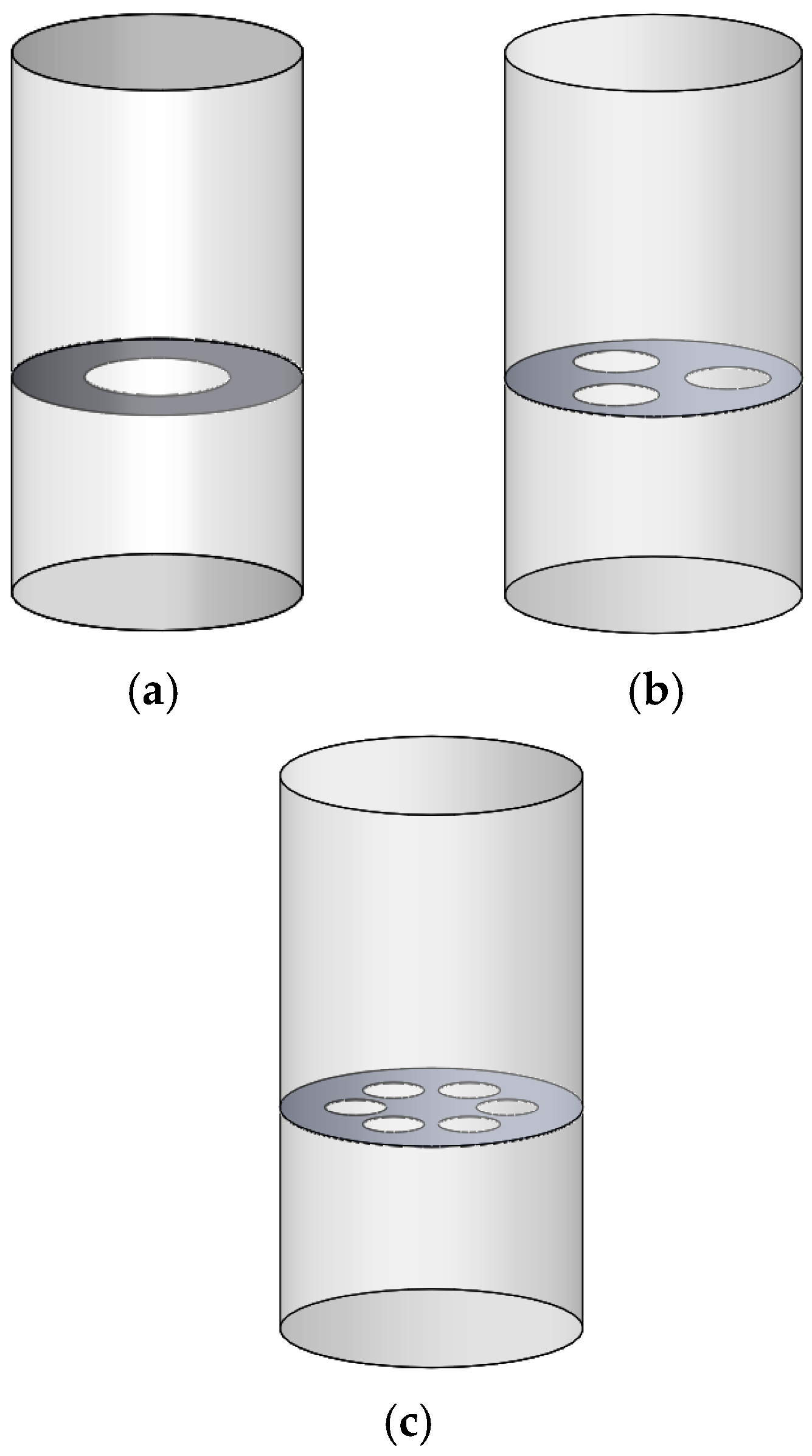
From the above research, it can be seen that the closer the damping plate is to the free liquid level, the better the sloshing inhibition effect of the liquid tank. In this section, the opening type of the damping plate is studied, and the inhibition effect of damping plates with different numbers of openings on the sloshing of the liquid tank is analyzed while keeping the position of the separator one fifth meter away from the free liquid level. The damping plates are all circular and remain perpendicular to the column, the amount of solid material remaining in the cross-sectional area of the baffle plate is almost the same, about 75%; the numbers of openings in the damping plates are one, three, and six, respectively; and the layouts of the different types of damping plates are shown in Figure 22.

Figure 22.
Layouts of different baffles. (a) 1 hole; (b) 3 holes; (c) 6 holes.
6.2. The Influence of Different Types of Damping Plates on the Amplitude and Pressure in the Liquid Tank
In order to further analyze the inhibition effect of different types of damping plates on the sloshing in the tank, this subsection compares the wave height elevation curves and the pressure on the left bulkhead for the three types of damping plates, and then obtains the average amplitude and maximum pressure in the tank with three different types of damping plates, so as to analyze the difference in the sloshing inhibition effect of different types of damping plates on the tank.
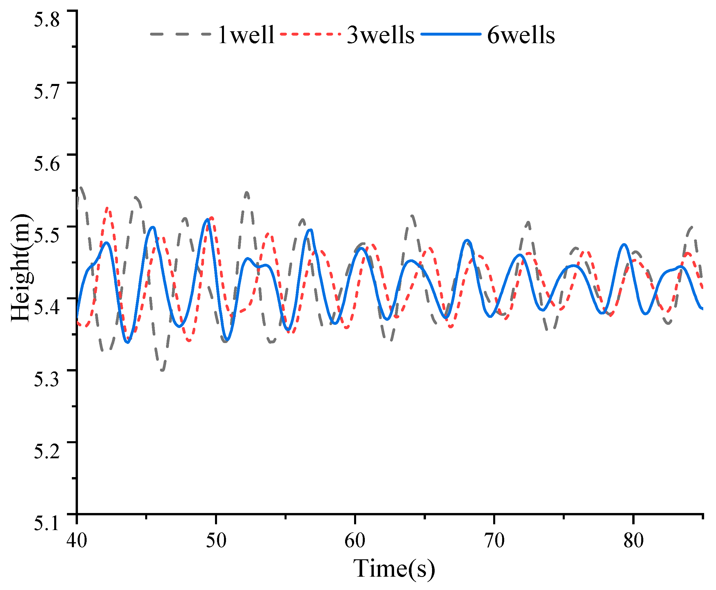
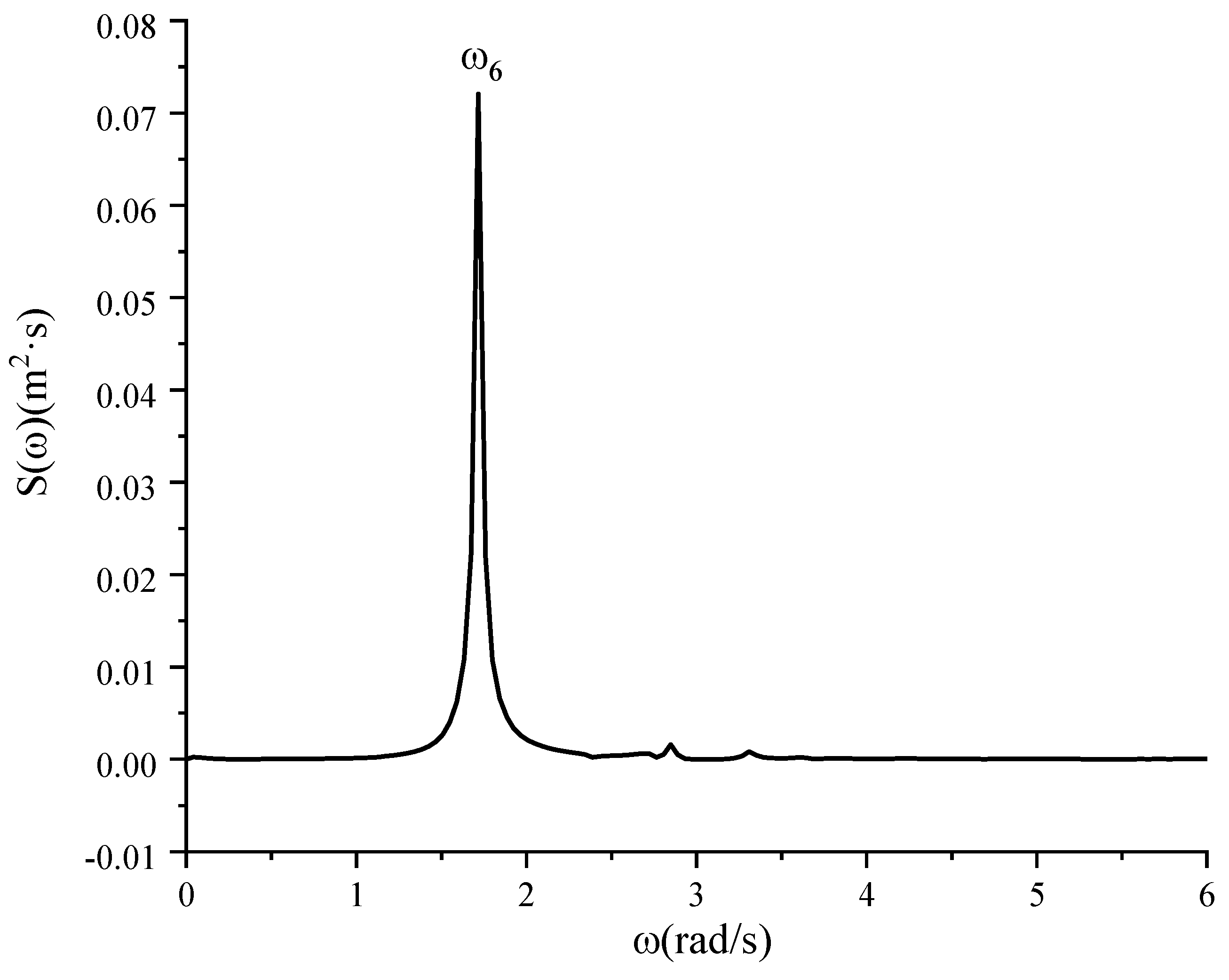
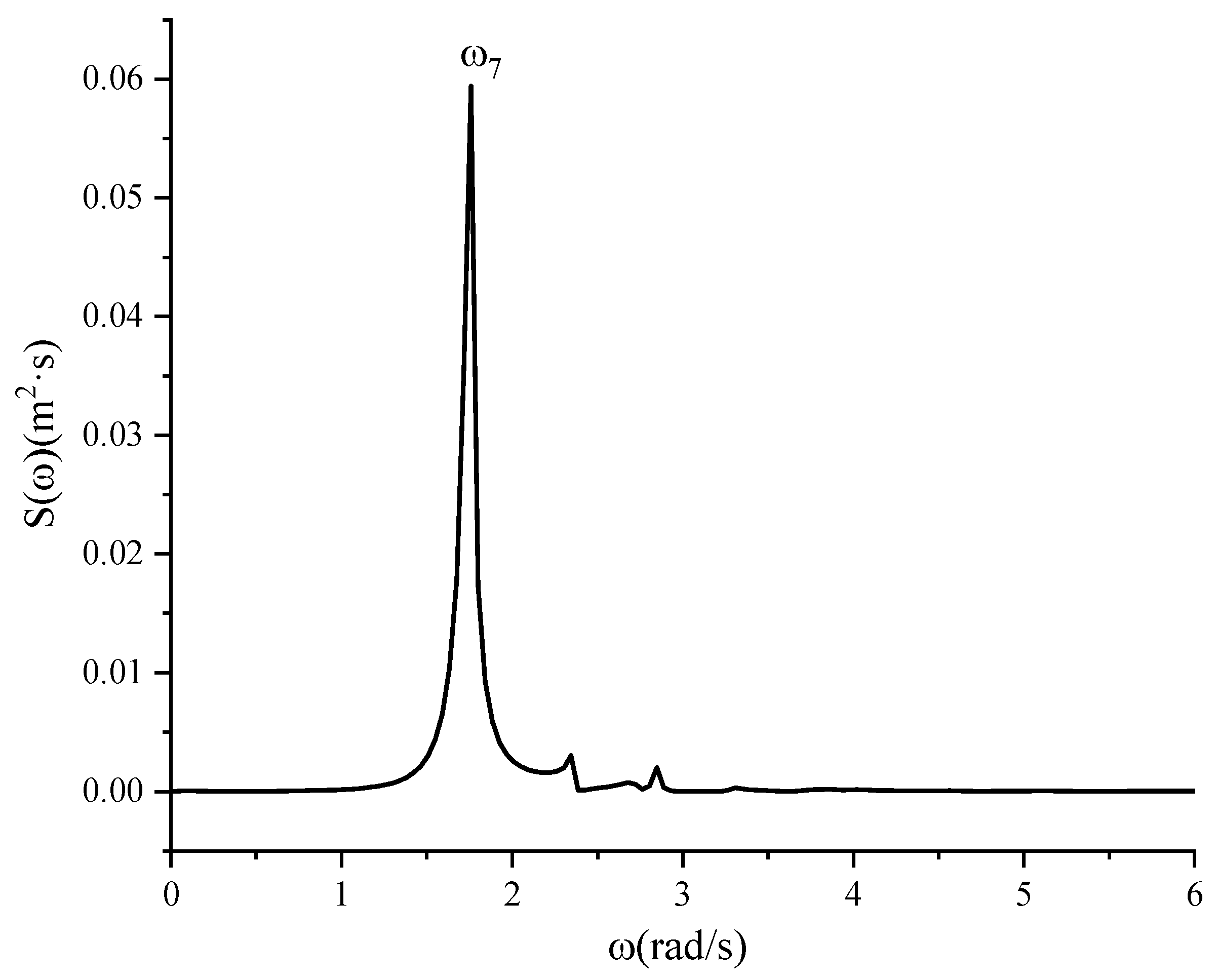
Figure 23 is the elapsed curve for the wave height at the left bulkhead of the liquid tank with different types of damping plates between 40 and 100 s; it shows that as time passes, the liquid-level height in the liquid tank also gradually attenuates, and at the same time, when the number of damping plate openings is three or six, the free liquid level attenuation amplitude is small, close to stable; and it can be seen from the analysis of the figure that when the number of holes in the damping plate is one, the average amplitude is 0.1465 m, and when the number of holes in the damping plate is three, the average amplitude is 0.0848 m, and the average amplitude difference is about 42.12%, indicating that when the opening rate of the damping plate is constant, the increase in the number of holes has a higher inhibitory effect on the liquid sloshing in the tank. When the number of openings of the damping plate increases to six, the average amplitude of the wave surface shaking is 0.0728 m; that is, for three more openings in the damping plate, the inhibition effect of the damping plate on the liquid sloshing in the liquid tank is not significantly improved. As shown in Figure 24 and Figure 25, when the number of openings in the damping plate is three, the natural frequency of the liquid level swing in the liquid tank is 1.747 rad/s, and when the number of holes in the damping plate is six, the natural frequency of the liquid level swing in the tank is 1.759 rad/s, compared with the natural frequency of 1.643 rad/s when the number of openings is one. The increase in the number of holes changes the natural frequencies to a certain extent; however, there is almost no difference between the natural frequency of the first-order wave surface sloshing when the number of holes in the damping plate is three and that when the number of holes in the damping plate is six, which indicates that with an increase in the number of holes in the damping plate, the inhibition effect on the liquid sloshing in the liquid tank is strengthened, but when the number of holes increases to a certain number, the inhibition effect is barely enhanced, which further verifies the above conclusion.

Figure 23.
The wave elevation curve of left bulkhead for different types of baffle.

Figure 24.
Energy spectrum of left bulkhead wave height variation duration curve (three open holes).

Figure 25.
Energy spectrum of left bulkhead wave height variation duration curve (six open holes).
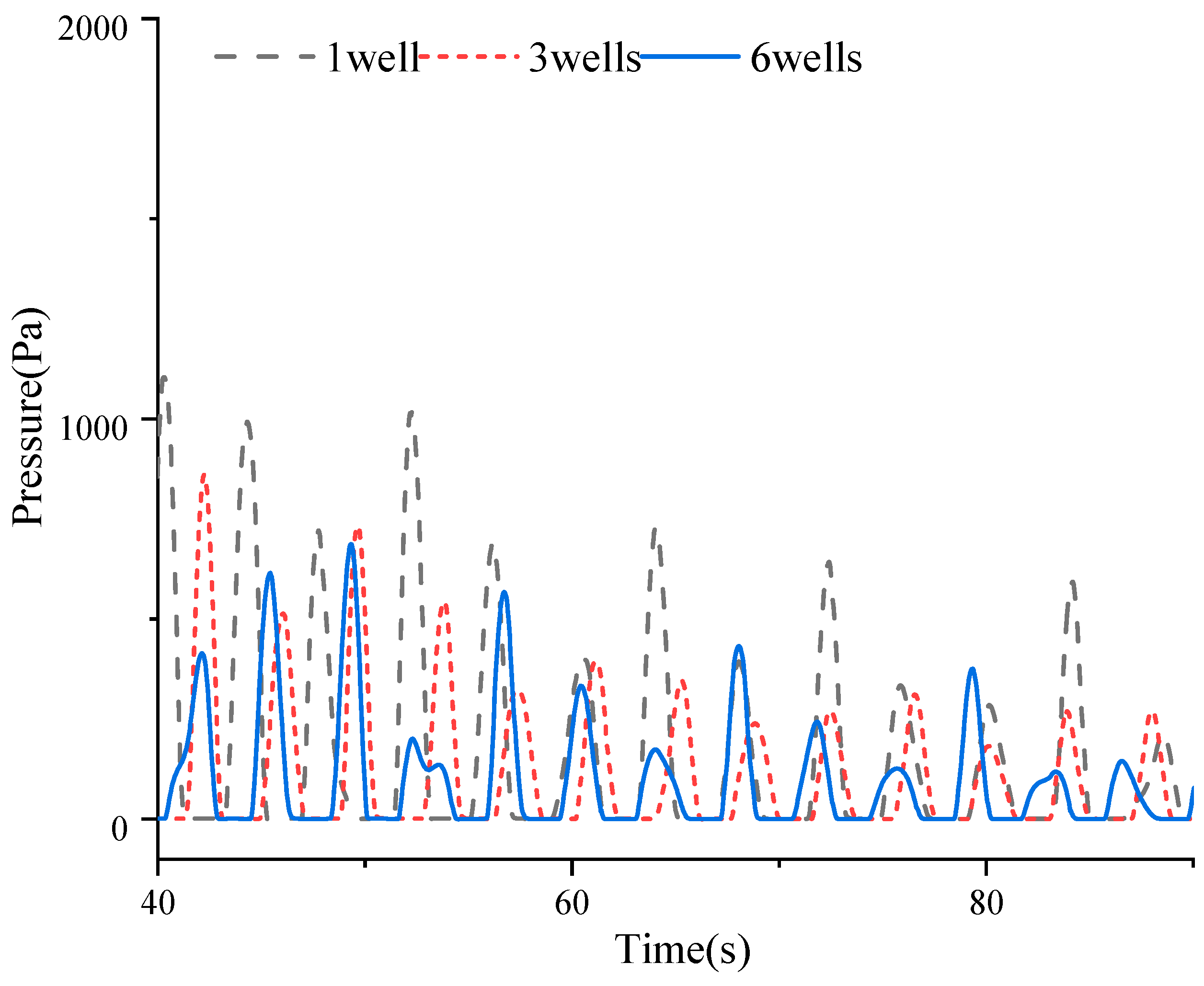
Figure 26 is the curve of pressure change at the center point of the left bulkhead of the liquid tank for different types of damping plates between 40 and 90 s; it shows that as time passes, the pressure on the left bulkhead of the liquid tank gradually decreases, which is similar to the phenomenon of the liquid swing amplitude in the liquid tank when the number of holes in the damping plate is one, because the liquid in the liquid tank still has a certain oscillation the left bulkhead is still subjected to a certain pressure, the maximum value of which is 1104.6 Pa. When the number of damping plate openings is three and six, the maximum pressure values are 853.60 Pa and 684.82 Pa, respectively, indicating that a greater number of damping plate openings can effectively reduce the force at the bulkhead, but the effect does not change significantly after reaching a certain number, and the number of damping plate openings needs to be reasonably set to reduce the impact of the liquid tank and improve its stability and safety.

Figure 26.
Pressure curve at center point of left bulkhead for different types of baffle.
7. Conclusions
First, this paper validates the numerical model based on a model in the literature. The reliability of the numerical simulation model of the cylindrical liquid tank in this paper is verified by comparing the calculated results of the numerical model with results in the literature and theoretical values.
Secondly, this paper takes the hypothetical liquid tank in the upright column of the maritime satellite launch platform (the model is the ideal model) as the research object, analyzes the free liquid surface movement of the liquid in the liquid tank with and without damping plates, and then sets up damping plates at different positions, as well as different types of damping plates, to analyze the influence of damping plates on liquid sloshing in the liquid tank, and draws the following conclusions:
- (1)
- With time, the free liquid level in the liquid tank gradually decays and finally reaches a stationary state. After adding the damping plate, the natural frequency of liquid sloshing in the liquid tank is changed, and the attenuation of the free liquid level height decreases sharply, which can effectively inhibit the liquid surface movement in the cylindrical liquid tank, and at the same time, the wave surface can reach a stationary state quickly.
- (2)
- In the case of the same type of damping plate, as the damping plate approaches closer to the free liquid level, the free liquid level shaking amplitude becomes smaller and smaller, and the pressure on the bulkhead is also significantly reduced, leading to a better inhibition effect on the wave surface movement of the liquid tank.
- (3)
- With an increase in the number of openings in the damping plate, the shaking amplitude of the free liquid level gradually decreases, and the pressure on the bulkhead gradually decreases when the position of the damping plate remains unchanged. For increases beyond a certain number of openings in the damping plate, the inhibition effect on the shaking wave surface motion of the liquid tank does not significantly improve. With the damping plate position held constant, a three-perforation configuration yields peak sloshing suppression efficacy in the liquid tank. Simulations demonstrate a progressive reduction in free-surface wave amplitude and tank wall pressure with increasing perforation count. However, beyond a critical perforation density, further aperture additions provide diminishing returns in wave elevation motion control.
8. Limitations and Future Work
The research presented in this paper remains at a conceptual exploration stage, and its conclusions are primarily based on idealized model conditions. Consequently, the study on the offshore satellite launch platform is not yet sufficiently in-depth.
- (1)
- This study is based on numerical simulation methods. Future research could conduct physical model tests to further validate and optimize the numerical analysis model presented here.
- (2)
- During the design of the damping plate in this study, the variety of parameters optimized was limited. Future work could focus on optimizing the design of the damping plate.
- (3)
- In this study, the launch platform model was simplified without considering factors such as the platform’s superstructure or rocket launch parameters. Future research could incorporate considerations of actual engineering aspects of offshore launch platforms.
Author Contributions
Conceptualization, Y.P., Y.W., F.L. and G.X.; Methodology, Y.P., Y.W., F.L. and G.X.; Software, Y.P., Y.W., F.L. and G.X.; Validation, Y.P. and Y.W.; Formal analysis, Y.P. and Y.W.; Investigation, Y.P. and Y.W.; Resources, Y.P. and Y.W.; Data curation, Y.P. and Y.W.; Writing—original draft, Y.P. and Y.W.; Writing—review & editing, Y.P.; Visualization, Y.P. and Y.W.; Funding acquisition, Y.P. All authors have read and agreed to the published version of the manuscript.
Funding
This research received no external funding.
Data Availability Statement
The original contributions presented in this study are included in the article. Further inquiries can be directed to the corresponding author.
Conflicts of Interest
All authors state that the study was conducted without any commercial or financial relationship that could be interpreted as a potential conflict of interest.
References
- Park, J.J.; Kim, S.Y.; Kim, Y.; Seo, J.-H.; Jin, C.H.; Joh, K.H. Study on tank shape for sloshing assessment of LNG vessels under unrestricted filling operation. J. Mar. Sci. Technol. 2015, 20, 640–651. [Google Scholar] [CrossRef]
- Yu, L.; Xue, M.; Zhu, A. Numerical Investigation of Sloshing in Rectangular Tank with Permeable Baffle. J. Mar. Sci. Eng. 2020, 8, 671. [Google Scholar] [CrossRef]
- Golla, S.T.; Venkatesham, B. Experimental study on the effect of centrally positioned vertical baffles on sloshing noise in a rectangular tank. Appl. Acoust. 2021, 176, 107890. [Google Scholar] [CrossRef]
- Ju, H.B.; Jang, B.S.; Ki-Ho, Y. Prediction of sloshing pressure and structural response of LNG CCS. Ocean Eng. 2022, 266, 112298. [Google Scholar] [CrossRef]
- Mccarty, J.L.; Stephens, D.G. Investigation of the Natural Frequencies of Fluids in Spherical and Cylindrical Tanks; National Aeronautics and Space Administration: Washington, DC, USA, 1960.
- Francescutto, A.; Armenio, V.; Rocca, L.M. On the roll motion of a ship with partially filled unbaffled and baffled tanks: Numerical and experimental investigation. In Proceedings of the Sixth International Offshore and Polar Engineering Conference, Los Angeles, CA, USA, 26–31 May 1996; Volume 3, pp. 377–386. [Google Scholar]
- Gawad, A.; Ragab, S.A.; Nayfeh, A.H.; Mook, D.T. Roll stabilization by anti-roll passive tanks. Ocean Eng. 2001, 28, 457–469. [Google Scholar] [CrossRef]
- Maleki, A.; Ziyaeifar, M. Sloshing damping in cylindrical liquid storage tanks with baffles. J. Sound Vib. 2008, 311, 372–385. [Google Scholar] [CrossRef]
- Storey, J.M.; Poothokaran, J.; Kirk, D.R.; Kirk, D.R.; Gutierrez, H.; Schallhorn, P.A. Experimental, Numerical, and Analytical Slosh Dynamics of Water and Liquid Nitrogen in a Spherical Tank. In Proceedings of the AIAA/SAE/ASEE Joint Propulsion Conference, Salt Lake City, UT, USA, 25–27 July 2016. [Google Scholar]
- Liu, J.; Zang, Q.; Ye, W.; Lin, G. High performence of sloshing problem in cylindrical tank with various barrels by isogeometric boundary element method. Eng. Anal. Bound. Elem. 2020, 114, 148–165. [Google Scholar] [CrossRef]
- Boroomand, B.; Bazazzadeh, S.; Zandi, S.M. On the use of Laplace’s equation for pressure and a mesh-free method for 3D simulation of nonlinear sloshing in tanks. Ocean Eng. 2016, 122, 54–67. [Google Scholar] [CrossRef]
- Morteza, G.; Mahmoud, G. Numerical analysis of fully non-linear sloshing waves in an arbitrary shape tank by meshless method. Eng. Anal. Bound. Elem. 2022, 144, 366–369. [Google Scholar]
- Sun, X.; Zhong, Y.; Feng, B.; Liu, C.; Yin, Y. Numerical Computation of Sloshing-Induced Force in Complex Ship Tanks under the Excitation of Ship Rolling Motion Based on the MPS Method. Appl. Sci. 2022, 12, 5130. [Google Scholar] [CrossRef]
- Zhang, K.K. Analysis and Anti-Sway Study of Liquid Sloshing in Liquid Tank Based on SPH Method. Master’s Thesis, Harbin Institute of Technology, Harbin, China, 2015. [Google Scholar]
- Leng, F. Research on Liquid Sloshing in Aircraft Fuel Tank with SPH Technique. Master’s Thesis, Nanjing University of Aeronautics and Astronautics, Nanjing, China, 2009. [Google Scholar]
- Liu, F. Dynamic Analysis of Liquid Sloshing and Sloshing Suppression Design for a Tank. Ph.D. Thesis, Nanjing University of Aeronautics and Astronautics, Nanjing, China, 2010. [Google Scholar]
- Wu, J.L.; Li, J.T.; Deng, Q.L.; Cheng, Y.; Wang, Y.Q. Numerical Research of Structural Damping on the Performance of the U Type Anti-rolling Tank. Ship Eng. 2020, 42, 80–83. [Google Scholar] [CrossRef]
- Luo, H.B.; Wang, C.B.; Sheng, Q.W. Numerical and Model Test on Eigen Characters of Rolling Motion of Anti-Rolling Tank. China Offshore Platf. 2020, 35, 1–6. [Google Scholar]
- Xue, M.A.; Lin, P. Numerical study of ring baffle effects on reducing violent liquid sloshing. Comput. Fluids 2011, 52, 116–129. [Google Scholar] [CrossRef]
- Dasgupta, A. Effect of Tank Cross-Section and Longitudinal Baffles on Transient Liquid Slosh in Partly-Filled Road Tankers; Concordia University: Montreal, QC, Canada, 2011. [Google Scholar]
- Budiansky, B. Sloshing of liquids in circular canals and spherical tanks. J. Aerosp. Sci. 2012, 27, 161–173. [Google Scholar] [CrossRef]
- Nema, P. Computational Study of Sloshing Behavior in 3-D Rectangular Tank with and Without Baffle under Seismic Excitation. Ph.D. Thesis, National Institute of Technology, Rourkela, India, 2014. [Google Scholar]
- Suyal, R. CFD Analysis of Fuel Sloshing in a Cylindrical Tank with and Without Baffles Under Linear Acceleration. Ph.D. Thesis, Concordia University, Montreal, QC, USA, 2016. [Google Scholar]
- Guan, Y.; Yang, C.; Chen, P.; Zhou, L. Numerical investigation on the effect of baffles on liquid sloshing in 3D rectangular tanks based on nonlinear boundary element method. Int. J. Nav. Archit. Ocean Eng. 2020, 12, 399–413. [Google Scholar] [CrossRef]
- Liang, L.H.; Wang, J.M.; Song, J.G.; Li, Y. Design and simulation investigation of variable period passive anti-rolling tank. Chin. J. Ship Res. 2021, 16, 147–154. [Google Scholar] [CrossRef]
- Zhao, M.H.; Wang, T. Influence of the Number of Longitudinal Baffles on Liquid Sloshing of Trapezoidal Tank. Pract. Technol. Automob. 2022, 47, 120–123. [Google Scholar] [CrossRef]
- Liu, D.X.; Wang, X.Y.; Chen, Y.J. Numerical, and Analytical Slosh Dynamics of Water and Liquid Nitrogen in a Spherical Tank. J. Mar. Sci. Eng. 2024, 12, 558. [Google Scholar] [CrossRef]
- Zhang, C.L.; Wang, L.Z.; Xu, M. Study on the Damping Effect and Mechanism of Vertical Slotted Screens Based on the BM-MPS Method. J. Mar. Sci. Eng. 2023, 11, 1270. [Google Scholar] [CrossRef]
- Zhang, Q.; Shui, B.; Zhu, H.H. Study on Sloshing Characteristics in a Liquid Cargo Tank under Combination Excitation. J. Mar. Sci. Eng. 2022, 10, 1100. [Google Scholar] [CrossRef]
- Mohapatra, S.C.; Islam, H.; Soares, C.G. Boussinesq Model and CFD Simulations of Non-Linear Wave Diffraction by a Floating Vertical Cylinder. J. Mar. Sci. Eng. 2022, 8, 575. [Google Scholar] [CrossRef]
- Versteeg, H.K.; Malalasekera, W. An Introduction to Computational Fluid Dynamics: The Finite Volume Method, 1st ed.; Pearson Education Limited: Chennai, India, 1995. [Google Scholar]
- Pan, L.J.; Wu, Z.J.; Zhang, J.F.; Zhang, B.M.; Du, S.Y. Modal analysis of liquid filled in tank applying Rayleigh-Ritz method. J. Harbin Eng. Univ. 2007, 1, 31–34. [Google Scholar]
- Dodge, F.T. The New “Dynamic Behavior of Liquids in Moving Containers”; Southwest Research Institute: San Antonio, TX, USA, 2000. [Google Scholar]
Disclaimer/Publisher’s Note: The statements, opinions and data contained in all publications are solely those of the individual author(s) and contributor(s) and not of MDPI and/or the editor(s). MDPI and/or the editor(s) disclaim responsibility for any injury to people or property resulting from any ideas, methods, instructions or products referred to in the content. |
© 2025 by the authors. Licensee MDPI, Basel, Switzerland. This article is an open access article distributed under the terms and conditions of the Creative Commons Attribution (CC BY) license (https://creativecommons.org/licenses/by/4.0/).