1. Introduction
Marine hose systems are key pieces of equipment in major engineering fields such as offshore oil extraction, deep-sea mining, and submarine communication. Especially in the development of submarine resources, the conveying hoses undertake the important task of transporting oil and gas, pulp, and connecting other equipment at the same time. In the actual production process, Marine hoses are generally operated in complex and changeable Marine environments, such as near-sea and deep-sea areas, where they have a large length-to-diameter ratio, which intensifies the flexible characteristics of the hoses. Therefore, under the constraints of the end conditions (such as the movement of mining vehicles and the vibration of ships [
1]), the conveying hose will deform and undergo configuration changes under the action of gravity, buoyancy, and ocean wave and current forces. If these changes cannot be reasonably monitored and controlled, in mild cases, it will cause fatigue damage to the hose, affect the connection performance at the end of the hose, reduce the service life of the hose, and interfere with the normal conveying operation of the hose. In severe cases, there may even be damage such as hose bending, breaking, and joint detachment [
2], causing huge economic losses and environmental pollution. Therefore, it is necessary to conduct research on the configuration changes of hoses under different conditions, in order to provide guidance for the early design of Marine hose systems and offer monitoring and forecasting means for later applications.
In the field of deep-sea mining, in order to lift mineral resources from the seabed to the land for people’s production and life use, scientists have proposed numerous schemes. Among them, the hydraulic lifting deep-sea mining system has become the mainstream research scheme in various countries due to its ability to stably and continuously transport seabed minerals [
3]. As shown in
Figure 1 specifically, the hydraulic lifting deep-sea mining system mainly consists of surface support ships, lifting hard pipes, lifting pumps, relay tanks, conveying hoses, mining vehicles, etc. The conveying hose is connected to the relay tank and the mining vehicle, and it is responsible for transporting the crushed pulp collected by the mining vehicle to the relay tank. It is equipped with a buoyancy block to ensure that the hose can maintain a stable spatial posture, allowing the mining vehicle to carry out the collection operation in sufficient space. At the same time, it also avoids the hose itself from sinking to the bottom or getting entangled. At present, scholars have achieved relatively fruitful results in the research on this type of hose, mainly focusing on the end constraint conditions (here mainly referring to the compliance of the conveying hose to the movement boundaries of seabed mining vehicles, etc. [
4]), the internal and external flow conditions of the hose, and the influence of the arrangement of buoyancy blocks on the hose configuration and stress distribution. Jian et al. [
5] adopted theoretical analysis and model tests to conduct force analyses and simulation calculations on hoses, mining vehicles, and relay compartments, and obtained the dynamic characteristics of the configuration changes of the conveying hoses. Xu et al. [
6] studied the effect of the position of the mining vehicle on the spatial configuration of the hose through a numerical simulation and an experimental analysis. Deng et al. [
7] conducted a model test on the conveying hose and concluded that the spatial displacement and stress magnitude of the hose were positively correlated with the movement range of the ore-collecting car.
In addition to conducting experimental research, scholars have also established various numerical models to simulate the responses of hoses under different working conditions. Oh et al. [
8] established a fluid-structure coupling dynamic analysis model to analyze the influence of the connection device at the connection between the relay chamber and the conveying hose on the stress magnitude at the end of the hose under different constraint conditions. Peng et al. [
9] studied the relative distance between the relay tank and the mining vehicle and the influence of the different mining paths of the mining vehicle on the spatial configuration of the flexible hose. Li et al. [
10] established a fluid-structure coupling model to study the spatial attitude changes and stress distribution of the conveying hose under the combined action of internal and external flows. Based on the simulation system of deep-sea mining flexible hoses, Yu et al. [
11] analyzed the morphological dynamic characteristics and laws of the hoses. The results show that the movement of mining vehicles and the internal flow in the pipeline are the main factors affecting the spatial morphology of the hoses. Wu et al. [
12] established a three-dimensional dynamic model based on beam elements according to the vector form intrinsic finite element (VFIFE) method. Through calculations, the spatial configuration and static internal forces of the mining pipeline system were obtained. Dai et al. [
13] analyzed the variation of the maximum bending moment of the hose under the combined action of internal and external flows based on the established multi-body dynamics model. Song et al. [
14] analyzed the sensitivity degree of the spatial configuration of the conveying hose to the changes of parameters, such as the external fluid flow velocity and direction, the internal pulp density, and the arrangement of buoyancy blocks. Chen et al. [
15] established a finite element model to analyze the configuration changes and stress distribution characteristics of the flexible hose under the combined action of the external wave flow and the traction of mining vehicles. Based on the three-dimensional finite deformation theory, Tong and Xia [
16] established a mathematical model of the flexible riser system and analyzed the static and dynamic response characteristics of the flexible riser. Xu et al. [
17] also conducted a finite element analysis of the dynamic response of the hose under different conditions of the position of the ore collector truck, ocean current velocity, and wind and wave levels, and obtained the displacement and stress variation laws of the hose, as well as the pressure loss of the fluid inside the pipe. Zhang et al. [
18] explored the influence of the weight and position of the buoyancy block, ocean current velocity, etc. on the spatial configuration of the hose based on the mechanical model established by Abaqus. Wang and Chen [
19] established an analysis model of the mining ship–pipeline system and analyzed the mechanical characteristics of the hose during the drift process of the mining ship. Xu et al. [
20] adopted the vector finite element method to study the influence of the incoming flow velocity, the number of buoyancy blocks, and the movement of the mining vehicle on the dynamic response of the conveying hose.
In conclusion, the conveying pipelines in the hydraulic lift deep-sea mining system mainly consist of two parts: a hard pipe and a flexible hose. The existing research on flexible hose equipment has achieved rich results. However, due to the fact that the hard pipe–flexible hose model consumes a large amount of human and material resources during the deployment and recovery processes, in order to reduce the cost of deep-sea mining operations, save time for deployment and recovery, and explore new, feasible deep-sea mining methods for future commercial exploitation, a fully hose-based conveyance method for deep-sea mining is proposed for the first time. According to the fully flexible-hose-based conveyance system developed and the requirements of the shallow sea test, the winches at both ends of the hose will be fixed at the ship’s rail position. Therefore, after the hose is laid out, it presents a “U” shape under its own weight, as shown in
Figure 2. Under the action of environmental loads, “U” shape hoses may encounter problems, such as bending and joint detachment, and they are prone to hose entanglement. To understand the underwater spatial configuration characteristics and the deployment and recovery performance of the entire hose, this paper uses Orcaflex software to simulate it. The influence of the top winch spacing and the incoming flow direction on the configuration changes and force conditions of the hose is mainly discussed. Furthermore, on the basis of the conventional research direction, the top tension changes in the hose and the underwater configuration characteristics during the specific stages of deployment and recovery are particularly considered.
2. Basic Principle
In complex Marine environments, the conveying hose system is mainly subjected to two types of loads: one is the force of ocean currents, and the other is the movement and force generated by the underwater conveying system induced by the movement of surface mining ships due to the wave loads acting on them. Regarding the influence of the internal slurry flow on the force of the hose, this paper simplifies it and only incorporates the internal flow as a mass module into the overall mass of the hose, without considering the dynamic loads, such as the inertial force caused by the internal flow. Therefore, this paper mainly focuses on the effects of ocean currents and waves and conducts the hydrodynamic performance calculation of the entire mining system under wave and current conditions. The calculation mainly adopts the three-dimensional potential flow theory.
For the calculation of wave forces on relatively small and slender cylinders, the Morison equation is still widely used in engineering design to calculate wave loads. It is a semi-theoretical and semi-empirical formula based on the theory of the flow around an object, as shown in Equation (1):
where
fw represents the wave force acting perpendicularly on a unit length of the pipe string;
ρw represents the density of seawater;
D is the outer diameter of the hose;
u and
y, respectively, represent the horizontal velocity and horizontal displacement of the wavy water quality point at the axis of the pipe string;
CD and
CM, respectively, represent the drag coefficient (drag force coefficient) and the inertial force coefficient.
There are mainly two key issues in applying Morison’s formula to calculate wave force: the first is to select a wave theory suitable for the sea area conditions to calculate the flow velocity and the fluid acceleration in the flow field. In hydrodynamic calculations, the Jonswap spectrum is selected for the irregular wave spectrum of the calculation model. This spectrum was measured and analyzed by the “North Sea Wave Joint Project”, and the average value of the given spectral shape parameter γ is 3.3. At the same time, it is also necessary to select the appropriate resistance coefficient, CD, and the additional mass coefficient, CA. According to the “Hydrological Specifications for Seaports” of China, for cylindrical structures with smooth surfaces, the CD and the CM can be selected as 1.2 and 2.0, respectively, and CM = CA + 1. Therefore, the value of the additional mass coefficient is 1.0.
Ocean current force is a kind of flow resistance acting on Marine structures. This resistance is a fixed-length flow resistance generated by the moving fluid. Ocean current can be approximately regarded as a stable planar flow. According to the principle that the resistance on underwater structures is a function of the fluid’s kinetic energy, the interaction between ocean currents and cylindrical structures can be expressed by the formulas of the planar flow and the vertical cylindrical load.
The ocean current force per unit length can be expressed by Equation (2):
where
fc represents the ocean current load per unit length of the cylindrical structure;
vcmax represents the maximum possible velocity of ocean currents.
The total ocean current force on a cylindrical structure is mathematically expressed as the resistance under stable flow conditions. The ocean current force
Fc is shown in Equation (3):
where
Fc represents the total force exerted by ocean current forces on the cylindrical structure;
represents the acceleration due to gravity;
S represents the total height of the riser; and
v represents the velocity of ocean current.
It can be seen from the formula that the main influencing factors for increasing the total ocean current force of the hard pipe are as follows: the resistance coefficient, CD, and the ocean current velocity, v. Among them, the ocean current velocity is set according to the height and the direction of the sea trial area as the profile flow velocity.
3. Computational Model
For the fully hose-based conveyance system, this paper mainly uses the dynamic analysis software Orcaflex 10.2, developed by the British Orcina Company, to carry out a simulation analysis. This software, based on multi-body dynamics and finite element methods, combined with computer technology, is capable of numerically calculating the interaction between Marine environment loads and structures. Orcaflex has a powerful ability to handle nonlinear behavior. Therefore, when it comes to the dynamic response of flexible structures to external forces, it can efficiently and accurately solve the deformation and stress distribution of the structure. It has a significant advantage in the design optimization and performance analysis of Marine structures, such as flexible pipelines, mooring systems, and buoyancy equipment.
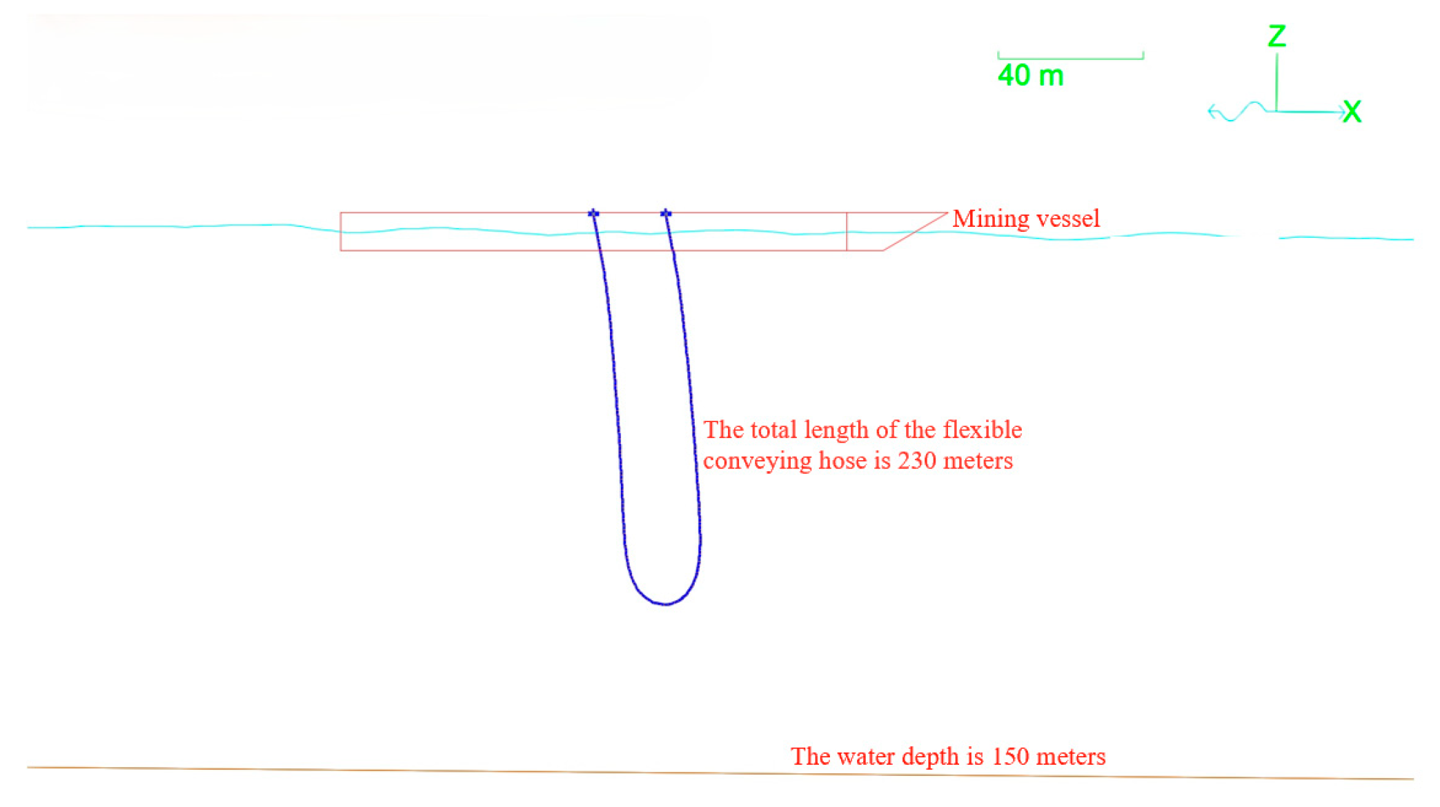
In this paper, a complete overall hydrodynamic model of the mining system is established in the simulation software Orcaflex, including the fixed seabed boundary, underwater transportation pipelines, surface mining ships, fluid flow conditions, etc. The established numerical simulation model is shown in
Figure 3. The three-dimensional potential flow theory is adopted, and the time-domain method is used for a coupling analysis. The time-domain coupling analysis method is a method that directly numerically solves the dynamic equation, allowing all nonlinear terms of the system to be taken into account, and it is used to handle strong nonlinear problems. Time-domain analysis can simulate the motion state of floating structures over a period of time under given conditions, truly reflecting the motion conditions under the actual complex combination of wind, waves, and sea current conditions.
In the simulation model of the fully hose-based conveyance system, the surface support ship adopted is the “Changhe Ocean” comprehensive test ship. The basic parameters of the ship’s hydrodynamic calculation are shown in
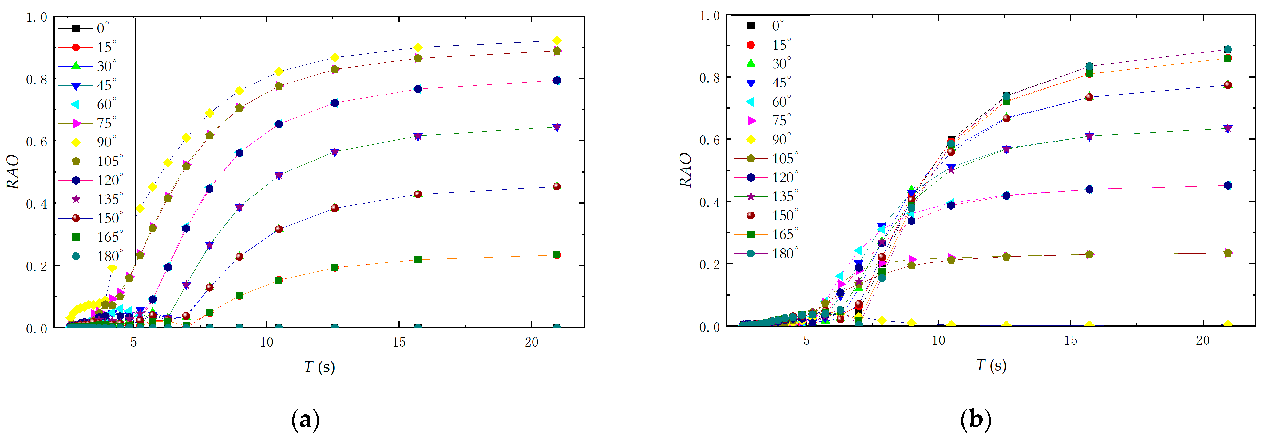
Table 1, among which the center of gravity coordinate is based on the baseline at the bottom of the ship. In the field of ship and ocean engineering, RAO (Motion Response Amplitude Operator) is generally used to reflect the six-degree-of-freedom motion response characteristics of structures. It represents the amplitude of the motion response (displacement, velocity, acceleration) generated by a structure at a specific degree of freedom under the action of a single wave amplitude. The RAO data of the offshore test mother ship in this paper is shown in
Figure 4.
In order to better simulate the real Marine environment, the sea area’s depth, wave parameters, ocean current parameters, etc., in the numerical model were set. According to the operational environment’s index requirements for the sea trial design, the operational water depth of the fully hose-based conveyance system is 150 m, and the wind speed is set at 15 m/s. The index requires that the hose can operate safely under the action of sea conditions of level four. Therefore, the wave conditions are selected as level 4 sea conditions (with a wave height of 2.5 m), and the ocean current conditions refer to the ocean current data of a similar water depth test area in the South China Sea during the non-typhoon period. The ocean current parameters are selected as the maximum ocean current velocity that occurs once a year; that is, a surface current of 1.09 m/s and a bottom current of 0.3 m/s.
The conveying hose selected in this article is a non-metallic, flexible, mixed conveying hose. To ensure the conveying performance of the conveying hose, the working water depth should be greater than 100 m. Considering that the underwater configuration of the flexible, mixed conveying pipe is in a “U” shape, the total length of the hose is set at 230 m. The specific parameter settings of the flexible, mixed transport pipe in the hydrodynamic calculation model are shown in
Table 2. The discrete node interval of the hose is 0.5 m, and the time step is selected as 0.01 s, according to the recommended step of the software.
In addition, the “U”-shaped, flexible conveying hose is connected to the winch on the mining ship. The specific connection points are as follows: The coordinates of the bow connection point (pump end) are (−10, −12.5, 6), and the coordinates of the stern connection point (recovery pipe) are (10, −12.5, 6). The connection points are 1 m away from the outside of the ship’s side. The connection method between the flexible conveying pipe and the ship is shown in
Figure 5. Except for in the deployment and recovery situations, the top of the hose is set as a fixed support in the other hydrodynamic calculation models.
4. Analysis of Simulation Results
4.1. The Analysis of the Influence of the Top Spacing of Flexible Conveying Hoses on the Configuration Characteristics of Hoses
Non-metallic, flexible conveying hoses are key pieces of equipment applied in fully hose-based underwater conveying solutions. Under the effect of their own weight, they naturally form a “U” shape. The constraint condition at the end of the flexible hose affects the configuration characteristics of the hose underwater. The non-metallic, flexible, mixed conveying pipe selected in this paper requires a minimum bending radius of 4 m and a diameter of 8 m. Therefore, the top distance of the flexible conveying hose should be no less than 8 m to avoid the excessive bending of and any bending damage to the hose. At the same time, considering the actual space layout of the sea trial ship, the distance between the winches should not exceed 24 m. Therefore, when exploring the influence of the top spacing on the configuration characteristics of the hose, the top spacings of 8 m, 10 m, 12 m, 14 m, 16 m, 18 m, 20 m, 22 m, and 24 m were selected. The operating sea conditions were at level four. The wave angle at the stern of the ship was always 30°. The surface current was 1.09 m/s, the bottom current was 0.3 m/s, and the flow direction angle was 0°.
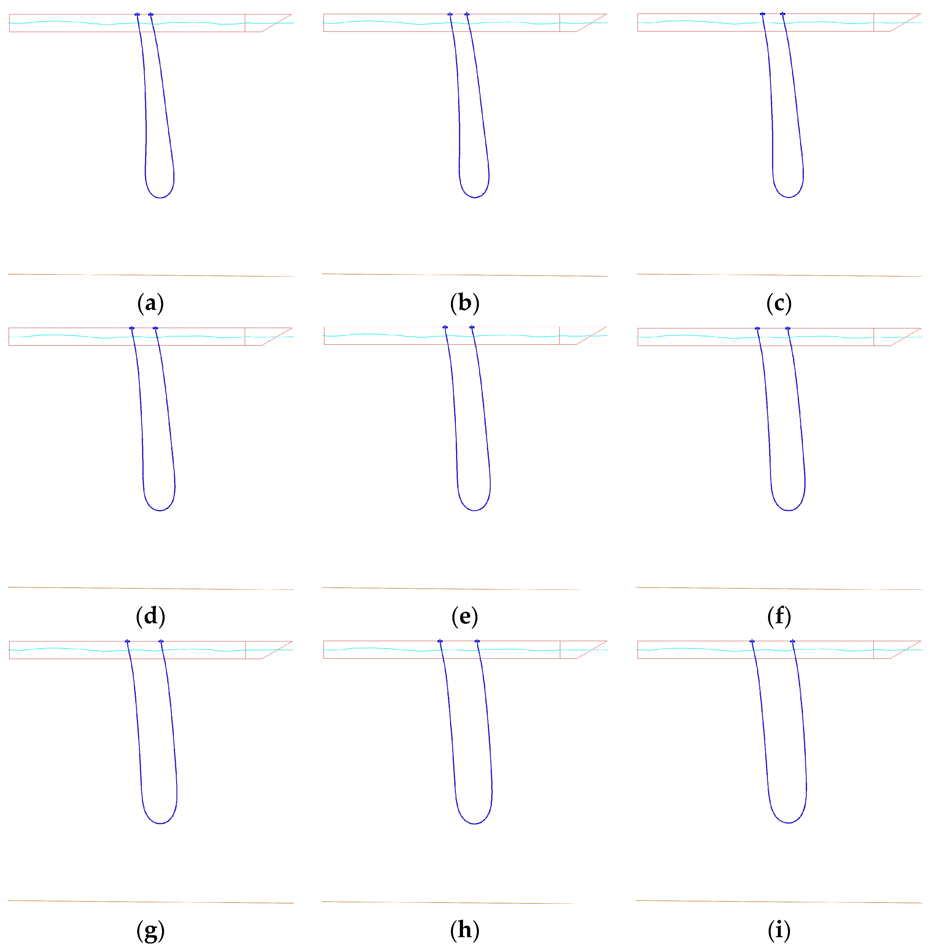
The numerical simulation results obtained are shown in
Figure 6. Through the configuration diagram of the flexible hose, it can be seen that under the combined action of wind, waves, and currents, the flexible conveying hose does not get entangled. The influence trend of different spacings at the top of the hose on the overall configuration characteristics of the underwater hose is generally consistent, with all presenting a “U” shape, and the hose, as a whole, shifts towards the bow along the flow direction, which is in line with the actual force response situation. The specific impact lies in that as the top spacing increases, the parallelism between the downward hose and the upward hose first increases and then decreases, which is consistent with natural cognition. From the perspective of the configuration, when the top spacing of the hose is 20 m to 24 m, the transitions between the downward hose, the upward hose, and the bottom curved section of the hose are relatively smooth, and the overall curved area of the hose is relatively small.
In order to further understand the force characteristics and configuration changes at the end of the hose, the load parameters at the end of the hose under each working condition were extracted, and the bending radius at the bottom of the hose was calculated, as shown in
Table 3. It can be obtained from the data in the table that the top tension of the hose at the bow end increases with the increase in the top spacing, while there is no obvious trend of change in the top tension of the hose at the stern end. Taking the minimum loads at the beginning and the end of the hose as the references, the maximum variation degrees of the loads at the beginning and the end of the hose were calculated to be 4.06% and 1.74%, respectively. It can be seen that the overall tension fluctuation range at the end of the hose is not large, and the force at the end of the hose is not highly sensitive to the change of the distance at the top of the hose. The bending radius at the bottom of the hose is always greater than the minimum required bending radius of 4 m for the hose, and it gradually increases with the increase in the top spacing. The curvature gradually flattens, and accordingly, the bottom configuration is also better. On the basis of ensuring that the force on the end of the hose is relatively small, the bending radius at the bottom of the hose should be large enough. Therefore, after comprehensive consideration, it can be concluded that when the top spacing is 20 m, the performance of the hose is relatively better than that it is with other spacings.
4.2. The Analysis of the Influence of the Ocean Current Direction on the Hose Configuration Characteristics
The real Marine environment is complex and changeable. Ocean currents will flow towards the conveying hose in different directions and have coupling effects. In order to explore the influence of the ocean current flow direction on the hose configuration and the force, the incoming flow direction angles were selected as 0°, 30°, 60°, 90°, 120°, 150°, and 180°. The top spacing was uniformly selected as 20 m, and the operating sea conditions were grade four. The angle of the bow facing the waves remained at 30°. The surface current of the ocean current was 1.09 m/s and the bottom current was 0.3 m/s.
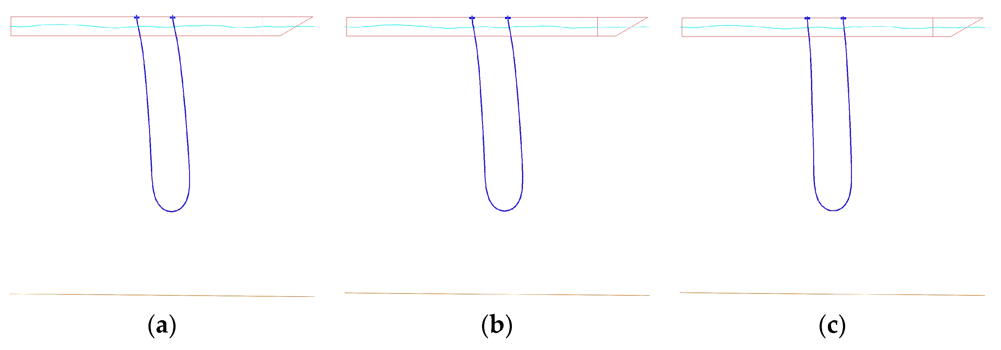
The numerical simulation results are shown in
Figure 7. It can be seen from the flexible hose configuration diagram that under the action of external environmental loads, the flexible conveying hose still maintains a good “U” shape configuration, and no entanglement phenomenon occurs. Due to the change in the direction of the incoming flow, the overall offset direction of the conveying hose has changed, always tending towards the direction of incoming flow. This is reflected in the figure as different degrees of offset towards the bow or the stern of the ship, which is in line with the actual force response situation.
Here, the load parameters at the top of the hose under various working conditions were also extracted, and the bending radius at the bottom of the hose was calculated, as shown in
Table 4. It can be obtained from the data in the table that with the continuous increase in the flow direction angle, the tension at the top of the hose at the bow end gradually increases, with a maximum change degree of 4.59%, while the tension at the top of the hose at the stern end shows a gradual decrease, with a maximum change degree of 1.07%. The overall tension fluctuation range at the hose end is small, and the sensitivity of the force at the hose end to the change of the incoming flow direction is low. The bending radius at the bottom of the hose also meets the design requirement of a minimum bending radius of 4 m. Moreover, with the increase in the incoming flow angle, it shows a trend of first decreasing and then increasing. When the flow direction angle is 90°, the bending radius is the smallest. However, since the top spacing has not changed, the overall change in the bending radius at the bottom of the hose is relatively small, which indicates from the side that the top spacing is the main factor affecting the size of the bottom bending radius.
4.3. The Analysis of the Hose Top’s Tension Characteristics During the Deployment and Recovery Processes
The fully flexible-hose-based conveyance system needs to achieve the deployment and recovery processes through the ship winch or other devices. The proportion of the underwater part of the conveying hose will constantly change during the deployment and recovery processes, and the wind, wave, and current effects it receives will also change accordingly. For this special stage, the load characteristics of the hose are analyzed. The relevant parameters are set as follows: top spacing 20 m, sea condition level four, bow wave angle 30°, surface current 1.09 m/s, bottom current 0.3 m/s, and flow direction angle 0°. Unlike the aforementioned research content, the fixation constraint condition at the end of the hose (the bow end) needs to be modified to the moving end. The hose deployment and retrieval speed should be selected based on the winch speed designed for sea trials, set at 6 m/min.
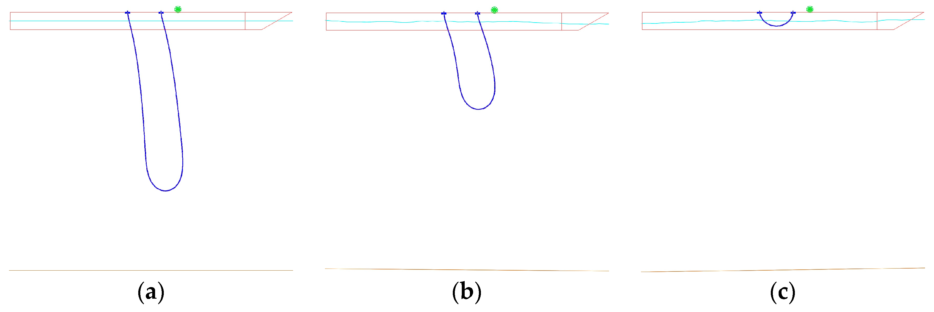
Figure 8 shows the hose configuration during the hose deployment process, and
Figure 9 shows the hose configuration during the hose recovery process. It can be seen from the configuration that during the hose deployment and recovery processes, the configuration is stable, and there are no phenomena such as entanglement or shaking. The conveying hose can complete the deployment and recovery operations smoothly along the initial direction.
The deployment and the recovery of the conveying hose are dynamic response processes.
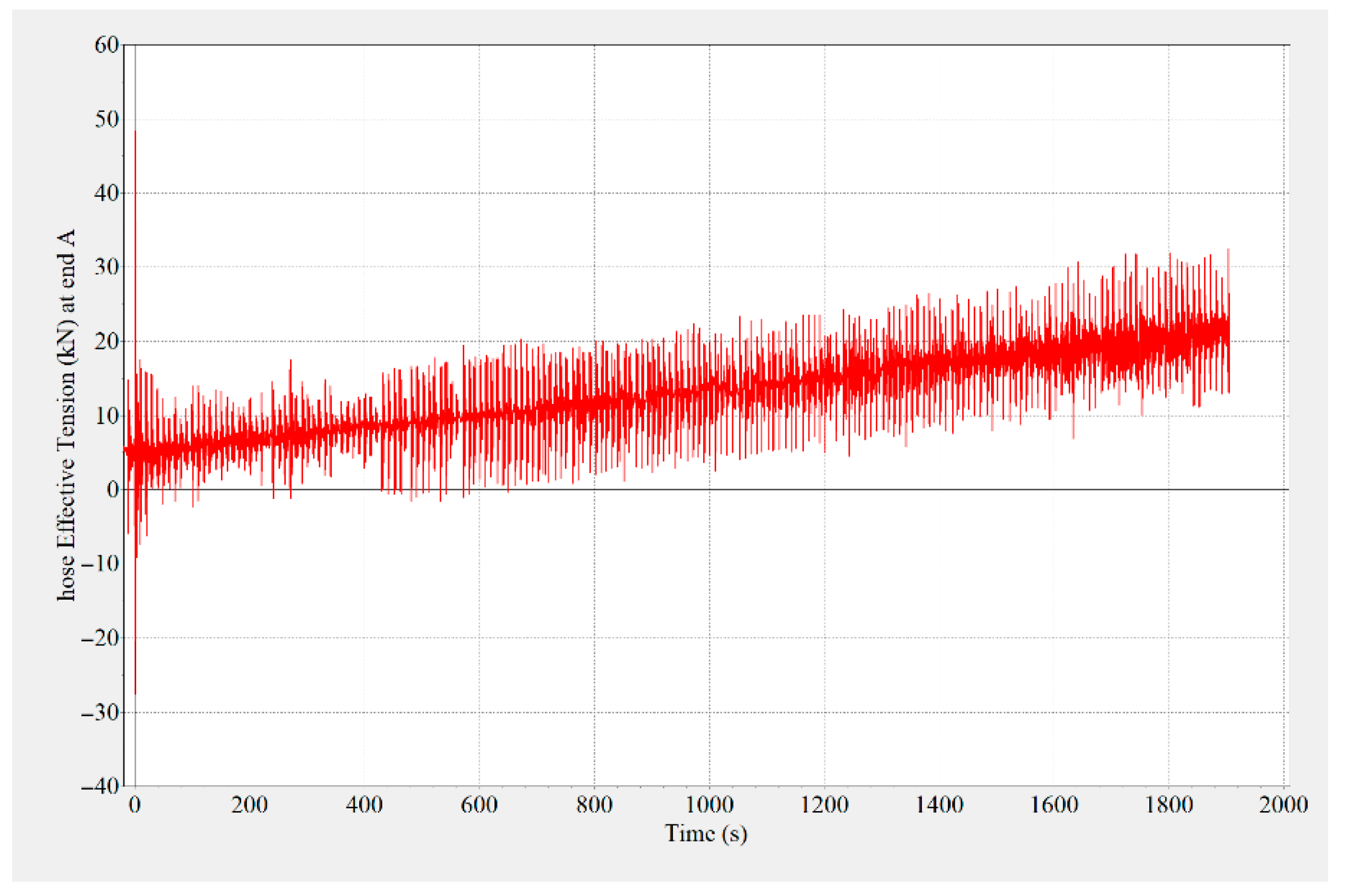
Figure 10 shows the tension variation curve at the fixed end (stern end) of the hose during the hose deployment process, and
Figure 11 shows the tension variation curve at the fixed end (pump end) of the hose during the hose recovery process. It can be seen that the steady-state tension at the top gradually increases during the hose deployment process. The reason for the peak fluctuation in the tension is the ship’s heaving motion. The steady-state tension at the top gradually decreases during the hose recovery process. Similarly, due to the heaving motion of the ship, the tension fluctuates up and down. During the deployment and recovery processes of the hose, the tension variation trend at the top of the fixed end was stable, with the maximum not exceeding 35 kN, and the tension load fluctuation was also within the safe range.
5. Conclusions
This paper proposes a fully hose-based conveyance method for the field of deep-sea mining and conducts a numerical simulation using Orcaflex software. The conveying hose studied presents a “U” shape in its spatial form. To explore the configuration changes and force conditions of this type of conveying hose underwater, numerical simulation studies under different top distances and different incoming flow directions were carried out. Meanwhile, the characteristics of the hoses in the specific stages of deployment and recovery were also analyzed specifically, and the conclusions obtained are as follows:
(1) From the numerical simulation results, it can be seen that the selected conveying hose in this paper can maintain good configuration characteristics under different working conditions, without phenomena such as entanglement and shaking, and it can well meet the requirements of the various index parameters of the shallow sea test. The specific parameters of the conveying hose are shown in
Table 2.
(2) The influence of the top spacing of the hose on the hose configuration is mainly reflected in the parallelism of the hoses at the bow and stern sides and the bending radius at the bottom of the hose. With regard to the top spacing, there is an optimal top distance with the best parallelism, which leads to less force at the ends and a bottom bending radius that meets the requirements. In this paper, the optimal top spacing is 20 m. When applied to the offshore test transportation system of non-metallic, flexible, mixed transportation pipes, the spacing of the hose winches ought to be 20 m apart. The top spacing of the hose has a relatively small impact on the top tension of the hose, and the top tension variation range does not exceed 5%.
(3) Under the influence of the incoming flow from different directions, the conveying hose mainly varies in the direction of the offset. Generally speaking, it offsets along the direction of the incoming flow. The direction of the incoming flow has a relatively small influence on the bending radius at the bottom of the hose. The end of the hose is less sensitive to the direction of the incoming flow when loaded, and the variation range in the top tension does not exceed 5%.
(4) During the deployment and recovery of the hose, the tension at the fixed end shows an increasing and decreasing trend, respectively. The corresponding tension fluctuations are caused by the heaving motion of the ship. The overall configuration of the hose always maintains a stable “U” shape during the deployment and recovery processes. Therefore, without adding counterweights, the hose can be safely deployed and recovered by using the automatic hose in water, a hose winch, and a hose tensioner.
This study focuses on the first proposed fully hose-based conveyance system for deep-sea mining. Through discussions on different working conditions, the underwater stability of the conveying hose was analyzed, providing theoretical guidance for the layout of Marine trial hose winches, hoses, and other devices. As this study focuses on the design of engineering test schemes, the aim is to ensure that the developed fully hose-based system can meet the requirements of shallow sea tests. The corresponding technical equipment has not been commercially applied, so the fatigue damage of the hose caused by cyclic loads, such as waves, ocean currents, and ship movements, has not been deeply considered. Meanwhile, the numerical simulation of sea conditions in this paper was always determined based on the sea trial design parameters and did not take into account the dynamic response characteristics of the conveying hose system under extreme sea conditions. These are all directions that can be further studied in the future.


